Article

Geologic Carbon Storage of Anthropogenic CO2 under the Colorado Plateau in Emery County, Utah

1
Department of Civil and Environmental Engineering, University of Utah, 110 Central Campus Dr., Suite 2000, Salt Lake City, UT 84112, USA
2
GE Global Research Center, 1 Research Circle, Niskayuna, NY 12309, USA
3
Carbon Solutions 820 S Henderson St., Bloomington, IN 47401, USA
4
Gianforte School of Computing, Montana State University, Bozeman, MT 59717, USA
5
Schlumberger, Denver, CO 80202, USA
6
Chevron Corporation, 1500 Louisiana St., Houston, TX 77002, USA
7
Hass Corporation, 1501 McKinney St., Houston, TX 77010, USA
*
Author to whom correspondence should be addressed.
Submission received: 10 February 2022 / Revised: 21 March 2022 / Accepted: 22 March 2022 / Published: 24 March 2022

Abstract

:
Geologic Carbon Storage (GCS) is a promising technology for storing large volumes of anthropogenic CO2 effectively and permanently. Numerical simulations are an integral part of site selection and characterization for any potential GCS site. As part of the DOE-funded CarbonSAFE Rocky Mountains Phase I project, a regional GCS analysis was undertaken to understand the efficacy of storing CO2 emissions from the power generation and heavy industry in central Utah’s favorable geology. In this study, the injection of CO2 for geologic storage was simulated in the Navajo Sandstone Formation in Emery County, Utah. Carbon dioxide was sourced from regional power generation stations and heavy industries throughout Utah, with an emphasis on emissions reduction at the Hunter Power Plant near Castle Dale, Utah. A simulation grid was extracted from the project’s geological model encompassing an area around Price, Huntington, and Castle Dale in central Utah. The Navajo Sandstone Member of the Glen Canyon Group was the target of CO2 injection with the overlying Carmel formation providing the primary seal. A suite of simulations was performed assessing the viability of this area for permanent CO2 storage. Results indicate that the area can not only store 46 million metric tons of anthropogenic CO2, meeting the project goals, but this area has the capacity to securely store at least 1.3 billion tons of CO2, suggesting the injection site and surrounding geology are suitable locations for commercial-scale GCS.

1. Introduction

There is a growing concern that the increasing atmospheric concentration of carbon dioxide will have potentially negative impacts on our economy and climate, according to the IPCC and the latest U.S. national climate assessment [1,2]. Carbon dioxide concentrations have increased from about 315 ppm in 1958 to over 418 ppm in 2022, according to the Mauna Loa Observatory in Hawaii [3]. Emissions of this greenhouse gas come from many areas of the global economy, such as energy generation, transportation, agriculture, and heavy industry. Eliminating the release of CO2 from these sources is critical for continued economic stability and prosperity [1,2]. A promising technology for addressing large point sources of carbon dioxide emissions is carbon capture coupled with geologic carbon storage (GCS) [4,5,6]. One of the critical components of a successful GCS program is a suitable storage site to ensure the long-term sequestration of this greenhouse gas.
As part of the Carbon Utilization and Storage Partnership (CUSP) of the Western United States, data gathered under the CarbonSAFE Rocky Mountain Phase I project was used to assess commercial-scale GCS, specifically the feasibility of storing a minimum of 46 million metric tons (50 million U.S. tons) of anthropogenic CO2 captured from a coal-fired power plant. The study area is located in the Price and Castle Dale area of the Colorado Plateau in central Utah, adjacent to the San Rafael Swell (Figure 1). The Navajo Sandstone, a part of the Glen Canyon Group, is the target GCS reservoir. We chose this area of the Colorado Plateau because of the potential to store vast quantities of anthropogenic CO2, due to the lateral continuity of its underlying geology and its proximity to several large point sources. This choice framed the central driving question for this study: “Can the Colorado Plateau serve as a regional geologic carbon storage complex for Utah’s point-source CO2 emissions?”.

2. Materials and Methods
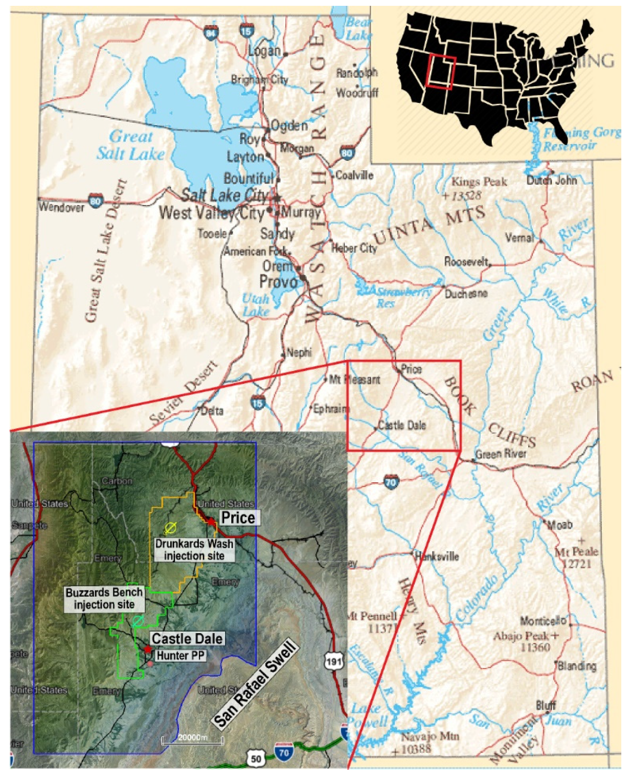
2.1. Study Site

The Price/Castle Dale area is just to the north and west of the San Rafael Swell, a northeast to southwest trending asymmetrical anticline with sedimentary strata of Mississippian to Cretaceous in age [7,8,9]. Two injection sites were evaluated, the primary site is located west of Castle Dale in the Buzzards Bench gas field, and a secondary site just south of Price in the Drunkards Wash gas field (Figure 1). Both sites currently produce gas and water from the Ferron coal and sandstone horizons, a Cretaceous aged sandstone and coal formation covering much of the area to the north and west of the Swell. The produced water from the Ferron production operations is injected into the deeper Navajo and Wingate formations for disposal, with injection operations currently ongoing [10]. The sedimentary structures in the area dip 2–5° to the west, consisting of alternating layers of sandstones, limestones, and shales [7,11]. The Glen Canyon Group provides a promising series of target formations with 20–1000 mD permeability, 10–20% porosity, and hundreds of feet of thickness [9,12,13]. The target reservoir is the uppermost formation in the group, the Navajo Sandstone. The Navajo Sandstone is overlain by interbedded, low porosity and permeability shales, limestones, and anhydrites of the Carmel Formation, which create an effective regional seal [12]. The Navajo Sandstone appears to offer the porosity, permeability, overlying sealing layers, and lateral extent to accommodate the project’s target injection mass of 46 million metric tons of CO2.
The Navajo Sandstone crops out along the spine of the San Rafael Swell south of the Drunkards Wash field and east of the Buzzards Bench field. Therefore, the area to the east of the Hunter Power plant and Buzzards Bench field lacks a structural trap, suggesting the potential for CO2 to migrate away from the injection zone and leak back into the atmosphere. Thus, areas to the west of the San Rafael Swell, including the Buzzards Bench site, would rely on solubility trapping, residual gas trapping, and long-term mineralization to permanently store the CO2. A feasibility study in western Australia explored the idea of relying on capillary trapping, residual trapping, and mineral trapping to secure the 220 Mt of CO2 [14,15]. The characterization and simulation study indicated that it was possible to store that volume of CO2 for greater than 1000 years without an intact stratigraphic trap [14,15]. On the northern and eastern flanks of the San Rafael Swell, several natural CO2 sources, such as Farnham Dome, have produced nearly 267,000 metric tons of CO2 during its lifetime [13]. Near the town of Green River, Utah, to the east of the study area, there is evidence of past CO2 seeps and geysers, along with a CO2 geyser created during exploration drilling that now serves as tourist attractions [13,16]. These nearby natural analogs indicates that this area of the Colorado Plateau has potential for permeant CO2 storage.

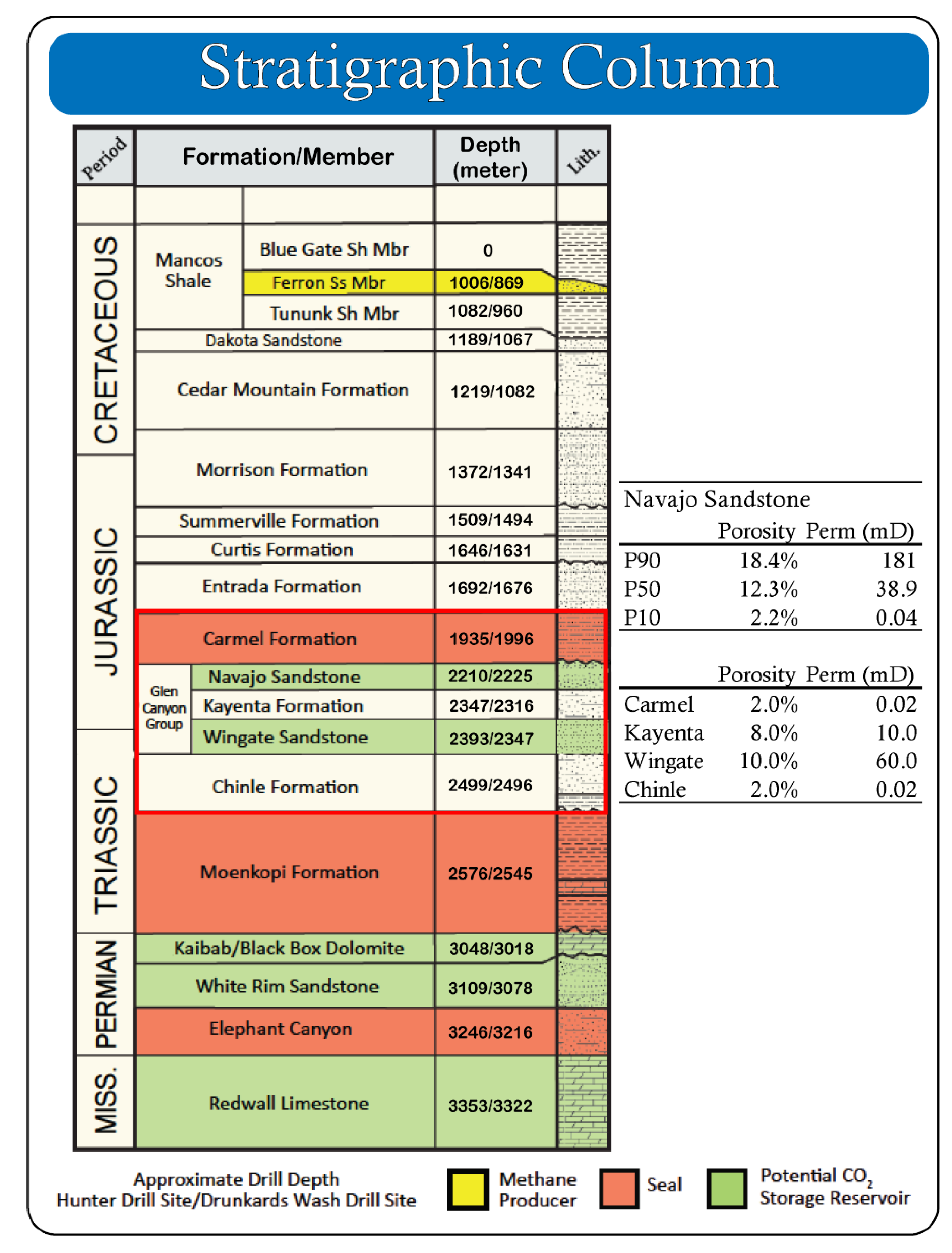
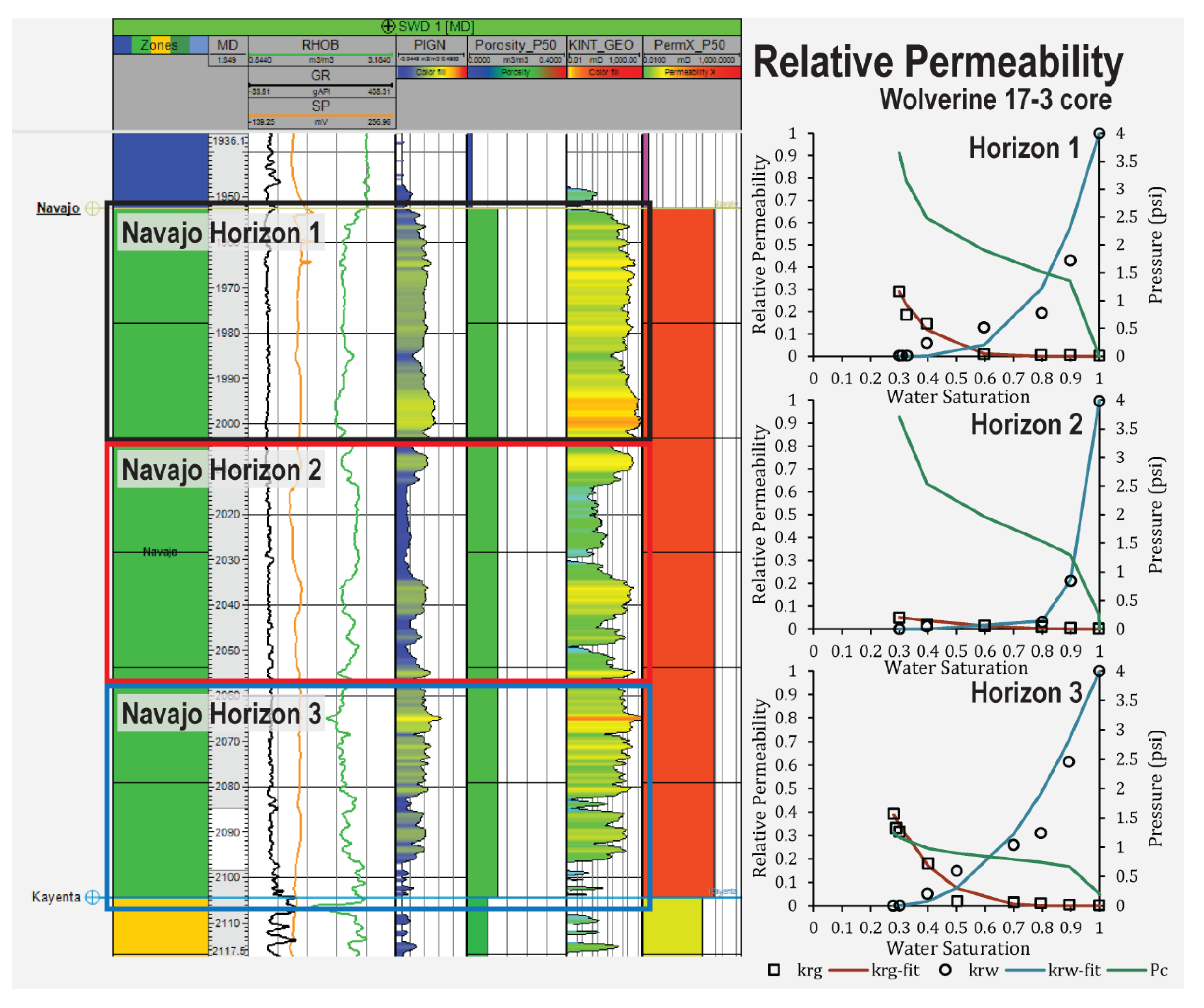
2.2. Site Characterization
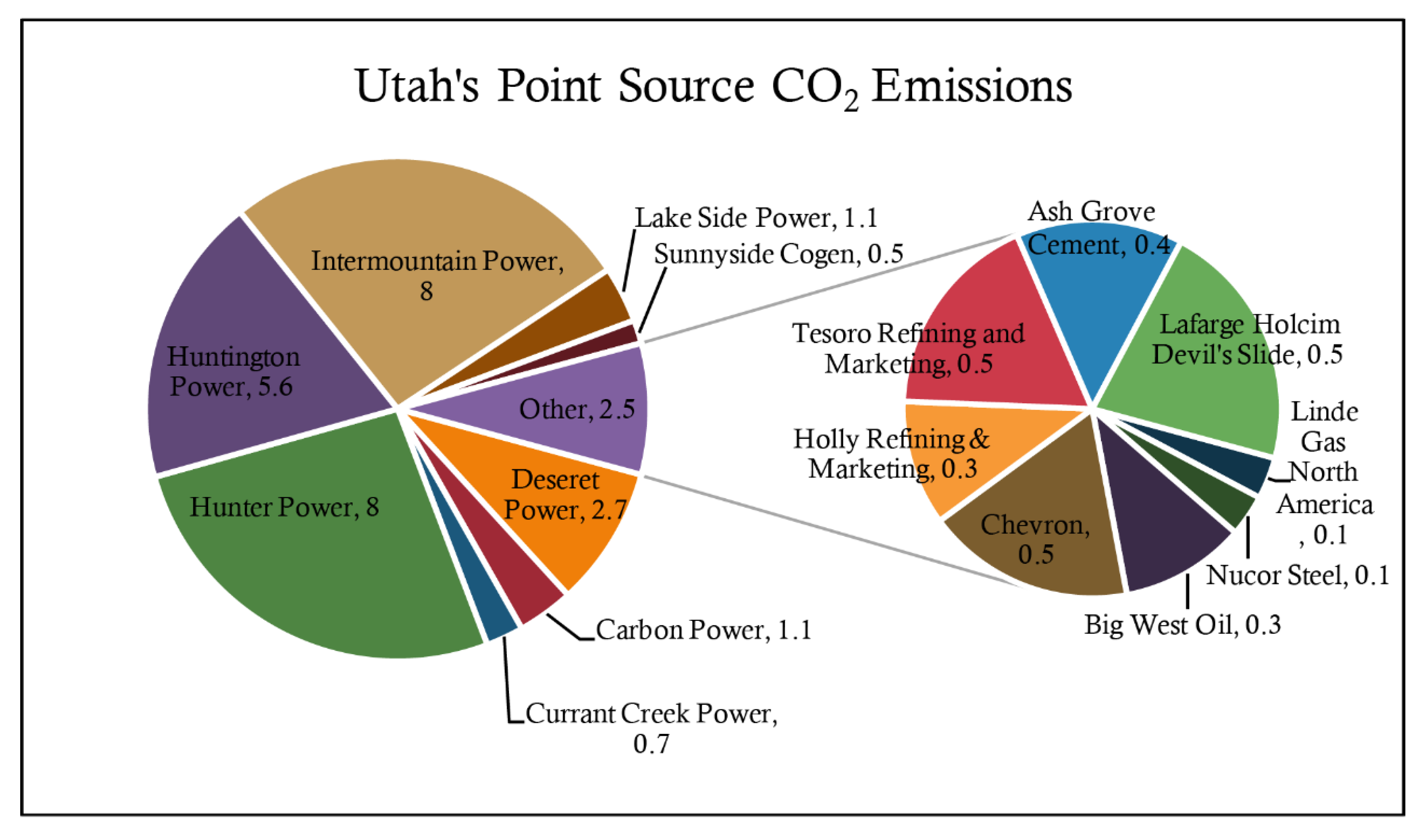
Petrophysical properties of the Navajo Sandstone were measured on legacy core from nearby wells and samples collected from outcrops in the Buckhorn Wash area of the San Rafael Swell [17,18]. A total of 2 wells 45 miles southwest of Castle Dale, Wolverine Federal No. 17-2 and No. 17-3, provided legacy porosity and permeability data along with legacy core for the Navajo Sandstone. These were the closest wells to the study sites that had core available for petrophysical analysis. Permeability and porosity were measured on core from well 17-2 and hand samples collected from exposed outcrop in the San Rafael Swell. Relative permeability and capillary pressure were also measured on core from well 17-2, detailed below. The data from the hand samples were not used directly because of excessively high values, likely due to surface alteration from weathering.
Within the study area, seven wells have detailed well log analysis (ELAN) to help estimate porosity and permeability. An additional 32 wells located across the area have an electronic well log, such as a gamma ray log and density log, and formation top picks used to identify and delineate formations. Near the Buzzards Bench site, 4 produced water disposal wells with ELAN analysis data between 3 and 8 km away from the proposed injection site. These 4 wells penetrate the Navajo Sandstone at between 1950 and 2145 m and have historic injection activities, with 2 of them (SWD 1 and SWD2) still injecting produced water currently [10]. In the Drunkards Wash field, there were 2 wells within 9 km of the proposed injection site that penetrate the Navajo Sandstone at between 1730 and 1840 m and have had a detailed well log analysis.
Fieldwork at a complete exposure of the Navajo Sandstone formation in Buckhorn Wash and well log data clearly show three main horizons. These 3 major horizons exhibit a wide range of porosity and permeability values, 3% to 19% porosity and 0.01 to 1000+ mD permeability [17,18]. A general stratigraphic column with depths at each injection site is shown in Figure 2, highlighting the potential seal formations in red and reservoir formations in green. The Ferron Sandstone is highlighted in yellow. In Figure 3, select well logs from well SWD 1 are displayed centered on the Navajo Sandstone interval, showing the three main horizons. Due to project scope, we assigned the Navajo Sandstone a homogeneous permeability and porosity distribution across all three horizons and assigned homogeneous permeability and porosity distributions to the rest of the formations (tabulated in Figure 2 and plotted in Figure 3). A key field observation that influenced this model design choice was that at a lateral scale of 350 m, the cells size for a flow model, the Navajo Sandstone was reasonably homogeneous. Even vertically, the three zones appeared very similar to each other.
A probability distribution of permeability and porosity was developed for the Navajo Sandstone from the well and outcrop data. Three homogeneous porosity and permeability distributions were sampled from this parameter space, corresponding to the data’s 10%, 50%, and 90% probability values. This yielded a low porosity and permeability model (P10), medium porosity and permeability model (P50), and a high permeability and porosity model (P90), see the table in Figure 2. The porosity and permeability values assigned to the other four formations (Carmel, Kayenta, Wingate, and Chinle) were constant through all model permutations. Data for these other formations were obtained from the literature, as the petrophysical analysis conducted by the project was focused on the Navajo Sandstone [12,13,19,20,21].
As part of the project’s characterization effort, the relative permeability and capillary pressure were measured for each of the three horizons identified within the Navajo Sandstone. These data were then converted to simulator curves and assigned to each of the three zones in the simulation model. The Wingate and Kayenta formations were assigned a generic sandstone relative permeability curve within Petrel© as no data are published or otherwise available for these formations. The Carmel, the regional seal for the Glen Canyon Group, and the underlying Chinle formations were assigned shale relative permeability curves from Bennion and Bachu (2007) [22]. Figure 3 displays the relative permeability and capillary pressure relationships assigned to each of the three horizons within the Navajo Sandstone. Capillary pressure within all other formations was estimated using the van Genuchten formula [23].

2.3. CO2 Sources

A primary goal of this study is to address the feasibility of storing 46 million metric tons (Mt) of anthropogenic CO2 emissions from a coal-fired power plant under the Colorado Plateau. The Hunter Power Plant (HPP) is the primary CO2 source for this study. The project determined that a realistic capture rate from one of HPP’s generation units was 1.7 Mt per year. At this rate, 27 years are required to capture and sequester 46 Mt of CO2. In addition to the HPP source, CO2 emission data collected as part of an economic analysis for the state of Utah were evaluated to determine sequestration targets for the regional GCS model [24,25,26]. Figure 4 summarizes Utah’s major CO2 point source emitters and their annual emissions. The overwhelming majority of the 30.2 Mt of CO2 emitted in Utah each year is from the energy generation sector. Only about 2.5 Mt of CO2 yearly emissions come from other industrial sources, such as cement manufacturing, petroleum refineries, and steel manufacturing. These data are used to design the injection schedule for regional GCS modeling.

2.4. Model Permutations

Three suites of simulation cases were created to explore different possible injection and storage schemes. The first simulation scenario was called the ‘Probability’ cases and labeled with the suffix P10, P50, or P90 in Table 1, focused on the injection of 46 million metric tons of CO2 over 27 years at each of the 2 injection sites, Buzzards Bench or Drunkards Wash, followed by 73 years of monitoring. The total injection rate was limited to 1.70 million metric tons per year. Three cases were run for each site using porosity and permeability values that correspond to the 10% probability values (P10), the 50% probability values (P50), and the 90% probability values (P90) discussed above. These six simulation cases are shown in Table 1.
The second simulation scenario was designed to evaluate the maximum injectivity of the formation. The total injection rate was limited by the theoretical maximum bottom-hole pressure (BHP) of 37.9 MPa (5500 psi). Three simulation cases were developed for this scenario, one case for each injection site (BB Capacity and DW Capacity) and then a case with injection at both sites simultaneously (BB&DW Capacity). These simulations were called the ‘Capacity’ cases and labeled with the suffix Capacity in Table 1, and were simulated over the same time period as the first simulation suite. They explore the total amount of CO2 that can be injected at each site if the injectivity of the formation determines the injection rate. These simulation cases use the P50 porosity and permeability data in Figure 2 for the Navajo Sandstone.
The third simulation scenario explores using the Buzzards Bench site, the Drunkards Wash site, and the surrounding area as a regional geologic carbon storage complex, labeled ‘Regional GCS’ in Table 1. This scenario explores our core question: “Can the Colorado Plateau serve as a regional geologic carbon storage complex for Utah’s point-source CO2 emissions?” The model uses the P50 porosity and permeability shown in Figure 2. Each injection well is limited to a maximum rate of 1 million tons/year with a secondary bottom-hole pressure limit of 37.9 MPa (5500 psi).

2.5. Model Domain and Initial Conditions

The reservoir model domain was developed from well top picks, well logs, and geologic cross-sections. Of the more than 2000 wells in the area, 77 extended below the Glen Canyon Group. Formation tops from these wells were interpolated to develop formation surface maps for the reservoir. The wells are located throughout the model domain, with the highest concentration of wells along the Buzzards Bench and Drunkards Wash gas fields to the north and west of HPP. These wells were used to develop the stratigraphic horizons and demarcate the area of interest, blue outline in Figure 1. The model domain is 71 km by 100 km centered roughly on Huntington, Utah, and includes the Carmel Formation (overlying seal unit), the Glen Canyon Group made up of the Navajo Sandstone (primary reservoir), the Kayenta Formation (secondary reservoir), the Wingate Sandstone (tertiary reservoir), and the Chinle Formation (underlying unit). Figure 2 summarizes the stratigraphic order of the formations. The model is discretized into 1,053,864 active cells. The model was truncated along the southeast section of the domain to model the area along the San Rafael Swell, where the Carmel and Navajo Sandstone crop out (Figure 5).
Local grid refinement was used for all the models except the ‘Regional GCS’ and ‘BB&DW Capacity’ models. The 2 injection wells needed at each site are located on the same well pad at the surface and deviate to 1 km apart at the injection horizon. Co-locating the injection wells allowed us to easily refine the grid by 2x in the x–y within a 10 km radius around injection wells. Because the models labeled ‘Regional GCS’ and ‘BB&DW Capacity’ in Table 1 have multiple wells sited in different locations, we did not use grid refinement around any of the wells to keep computational overhead manageable.
The boundary conditions for the model were developed to mimic the regionally continuous nature of the Glen Canyon Group. The lateral boundaries are set to infinite volume cells so that a constant head is maintained, and the top and bottom boundaries are set to no flow. The San Rafael Swell infiltrates roughly 3.7 × 10⁶ m3/year (3000 acre-ft/year) of rainfall into the Navajo Sandstone along about 376.4 km2 (93,000 acres) of outcrop area [12]. This infiltration rate was modeled by setting the top layer of cells along the outcrop to a constant flux of 27 cm3/day of water per square meter.
Initial conditions were developed in two stages. First, a 1000-year simulation was run to establish equilibrium between hydrostatic conditions and the specified aquifer recharge to represent the pre-produced water injection conditions. The resulting pressure distribution was then applied as the initial conditions to a second simulation that modeled the historically produced water injection occurring in the Navajo Sandstone at Buzzards Bench gas field from January 1996 to January 2018. The results of this second simulation were used to create the pressure distribution used to initialize all subsequent model permutations.

2.6. Injection Wells

This project faced several significant constraints when selecting the location of the injection wells. Its location would need to be either on HPP property or State of Utah School and Institutional Trust Lands Administration (SITLA)-owned land to streamline land ownership hurdles. Other factors, such as distance to any known outcrop, depth to the injection zone, maximum injection rate, and existing surface infrastructure, were considered. The ideal location for the project injection well would be on the HPP site as it would make land ownership easier and minimize surface infrastructure, such as pipelines. The Navajo Sandstone is 1300 m deep, directly below the plant, but crops out about 15 km to the southeast. The reservoir hydrostatic pressure 6.4 km up-dip from the power plant is above 7.4 MPa (near the triple point of CO2), causing a potential phase change from supercritical to gas. Preliminary simulations showed that under certain conditions the CO2 had the potential to migrate up-dip to this area of the reservoir within 50 years of ceasing injection, indicating that this area was not appropriate for long-term CO2 storage. Due to this initial finding, the primary injection well location was moved 9 miles northeast to an existing well pad site within SITLA property boundaries (Figure 1). A secondary or ‘backup’ injection site was located 28 miles north of HPP in the Drunkards Wash field, also sited on an existing well pad located on SITLA land (Figure 1). Both sites were chosen with existing surface infrastructure in mind, so that wells are located in areas that have road access.
Well-design considerations suggest that a single CO2 injection well could only realistically accommodate 1 million tons per year. To meet the maximum expected capture rate of 1.7 Mt/yr requires 2 injection wells at each site. At this injection rate, the storage target of 46 million metric tons of CO2 will be met within 27 years (Table 2). The injection wells are modeled as deviated wells to minimize surface impacts, sharing the same well pad, but becoming 1 km apart at the top of the Navajo Sandstone injection interval. The bottom-hole pressure is assigned to 80% lithostatic for all simulation suites, about 33 MPa (4800 psi) at both injection sites. The wells in the P10, P50, and P90 cases use a combined surface injection rate of 2,347,358 m3/day (1.7 Mt/yr). The injection scheme for the three ‘Capacity’ simulations used a different approach. The bottom-hole pressure limits the injection rate for each well. This criterion indicated the maximum fluid injection that the formation can support without exceeding 80% of the formation’s lithostatic pressure, about 33 MPa (4800 psi) at both sites (Table 2).
In the ‘Regional GCS’ case, over 30 million metric tons of CO2 was injected into the model per year, Utah’s yearly emission rate from its major point sources. To accommodate the additional CO2, 17 injection wells were added to the model for a total of 21 wells. This produces a 1.45 Mt/yr injection rate per well. This rate is higher than the 1 Mt/yr injection rate limit we specified for the other scenarios, but still reasonable for an injection well. These additional wells were selected from across the western margin of the valley between the San Rafael Swell and the Colorado Plateaus to the west (Figure 5). These include sites of currently plugged and abandoned wells and were selected for their location in the valley, existing surface infrastructure, such as roads and well pads, and distance from the Navajo Sandstone outcrop locations.
The injection schedule adopted for the ‘Regional GCS’ case incrementally reduces the injection targets through time to represent a gradual phase-out of fossil fuel power generation through the first 50 years of simulation and an end to fossil fuel use in heavy industry within 100 years, as described in Table 2. In this scenario, CO2 is injected at 30.4 Mt/yr for the first 30 years of the simulation to simulate current emissions. At the end of 30 years, emissions from Hunter and Huntington power plants are ceased, reducing the injection rate target to 16.8 Mt/yr, while keeping the same number of active injection wells. At +40 years, the injection rate target is reduced to 8.8 Mt/yr when emissions from the Intermountain Power Project are ceased. This allows 11 wells closest to the outcrops to be shut. At +45 years, the emissions from the Bonanza power plant are stopped, reducing the injection rate to 6.1 Mt/yr, with 3 more wells shut. At +50 years, the rest of the emissions from the power generation sector are eliminated, reducing the injection rate to 2.5 Mt/yr and closing another 4 wells. This leaves only three wells in the Drunkards Wash area still actively injecting CO2; the two project wells, Drunkards Wash #2 and #3 and Gordon Creek Unit 5 well. These 3 wells continue CO2 injection for the next 50 years before ceasing all injection activities in year 2118, see Table 2. The model then continues simulation for an additional 900 years for monitoring the long-term CO2 plume movements and storage security of this potential site.
In addition to the wells discussed above, three produced water disposal wells located in the Buzzards Bench field inject produced water from gas production operations in the Ferron coal into the Navajo Sandstone. Historical injection data were obtained and used to model the initial conditions and estimate a forward simulations injection schedule. Two of the three produced water disposal wells show current injection as of February 2018. These two wells were simulated in the forward models with a continuous injection of produced water for 20 years.

3. Results

The results indicate that storing far more than the project mandated 46 million metric tons of anthropogenic CO2 at either the Buzzards Bench or the Drunkards Wash injection site is feasible. We forecast the ‘Regional GCS’ simulation case to be capable of storing just under 1.3 billion metric tons of CO2 with no loss of containment over 1000 years, suggesting that this area would make an excellent commercial-scale GCS complex for not just the Hunter and Huntington power plants, but all of Utah’s point-source emissions. Under all conditions simulated for this study, the Navajo Sandstone and the greater Glen Canyon Group exhibit sufficient capacity and injectivity to accommodate at least 46 million metric tons of CO2. When the project wells were allowed to inject at their bottom-hole pressure limits, these formations could accommodate upwards of 113 million metric tons of CO2 at Buzzards Bench and more than 123 million metric tons of CO2 at Drunkards Wash, see Table 3. When injection ceases, pressure returns to the pre-injection range within a couple of years.
Only a single simulation case, the Buzzards Bench P10 case, was unable to store the target amount of 46 million metric tons of CO2 (Table 3). The low permeability (0.04 mD) and porosity (2.2%) of this case limited injection in the first two months, due to the bottom-hole pressure reaching the limit. As the simulation proceeded past this point, CO2 breaks through to the Kayenta, reducing the pressure due to the higher permeability (10 mD) of this formation, allowing the wells to inject at the maximum capture rate. This resulted in about 90,700 metric tons less CO2 being injected in the Buzzards Bench P10 case compared to the rest of the cases within the first simulation scenario, the ‘Probability’ cases from Table 1.
Supercritical CO2 accounts for greater than 80% of the injected mass in all simulation cases. Only about 6% of this supercritical CO2 is trapped in the pore space as a residual phase, in line with expectations [14,27,28,29]. The simulation results indicate that mobile supercritical CO2 has the potential to migrate away from the injection wells through buoyancy-driven flow, due to the high permeability and porosity of the entire Glen Canyon Group. The CO2 plume spreads out laterally around the injection wells, but does not move towards the outcrop area of the model. The plume moves slightly west at the Drunkards Wash injection site, as there is a minor structural trap in this area. Whether this is a structural trap in this area or it is just an artifact of possibly inaccurate well tops, and smoothing algorithms would require further investigation. There is a clear path up-dip at the Buzzards Bench location for the CO2 to migrate towards the outcrop area and potentially escape containment. However, this is not observed in any of the simulation cases. The CO2 does spread laterally around the wells, but it stays in the vicinity of the injection wells and does not move up-dip towards the outcrops. This is due to the simulated surface water infiltration into the Navajo Sandstone along the outcrop area of the model, creating an above hydrostatic pressure gradient up-dip of the injection site. This pressure gradient impeded the buoyancy-driven upwards migration of the CO2 plume, keeping it trapped near the injection well.
Both the Buzzards Bench and Drunkards Wash injection sites show good containment potential. Still, there are significant differences concerning the CO2 phases present, either supercritical CO2 or CO2 dissolved in the aqueous phase. At the Buzzards Bench site, CO2 dissolved in the aqueous phase makes up a higher fraction of the CO2 in place under high permeability and porosity conditions (P90), at 15.9% versus the P10 case at 10.6% (Table 3). Under low permeability and porosity conditions (P10), more CO2 is forced into the higher permeable formations underlying the Navajo, while constraining its lateral movement within the target reservoir. This leads to the limited lateral migration of the supercritical CO2 plume, resulting in less dissolution of CO2 into the aqueous phase (Table 3). Under high permeability and porosity conditions (P90), less CO2 migrates into the lower layers, with most of it spreading out along the top of the Navajo Sandstone. The increased lateral movement allows more CO2 to contact unsaturated brine, leading to the increasing CO2 dissolution in the aqueous phase.
At the Drunkards Wash injection site, there is more dissolved phase CO2 in the P10 case than in the P90 case, though only by 1.2% (Table 3). This is likely due to the Glen Canyon Group being over 91 m thicker at the Drunkards Wash site (258 m) than at the Buzzards Bench site (155 m), and the low permeability and porosity of the Navajo in the P10 case that forces more CO2 into the higher permeability Kayenta and Wingate units. Unlike at the Buzzards Bench site, the extra vertical capacity at Drunkards Wash allows the CO2 plume to contact more of the unsaturated formation brine, promoting dissolution and aqueous trapping. Under higher permeability and porosity cases (P50, P90), the CO2 plume can rise vertically and spread out laterally along the base of the Carmel Formation. Due to the larger volume of Glen Canyon Group at the Drunkards Wash injection site, the plume can contact roughly the same volume of unsaturated brine, regardless of the porosity and permeability assigned to the Navajo Sandstone. The results suggest that either injection sites will make a suitable GCS location.
Injection under the bottom-hole pressure limiting scheme dramatically increases the mass of CO2 that can be injected into the Navajo Sandstone, compared to the rate-limiting method used in the ‘Probability’ cases. The results of the ‘Capacity’ cases indicate that almost three times the mass of CO2 can be stored at each site, compared to the ‘Probability’ cases (Table 3). At the Buzzards Bench site, 112.8 million metric tons were stored, 90% of which was still in the supercritical phase at the end of the simulation (Table 3). At the Drunkards Wash site, 123 million metric tons of CO2 were stored, with 87% in the supercritical phase (Table 3). When CO2 was injected at both locations simultaneously, a total of 201.1 Mt was stored over 30 years (Table 3). That is roughly 7.7 Mt per year, only slightly less than the total emissions from Hunter Power Plant, at 8 million metric tons per year.
The final simulation case, the ‘Regional GCS’ case, indicated the capacity to store all of the anthropogenic CO2 emissions from all of Utah’s major point-source emitters over the next 100 years. The ‘Regional GCS’ case stored approximately 1.3 billion metric tons of CO2 across the Castle Dale/Price area (Table 3). Unlike the other cases, this case shows that 25% of the CO2 may dissolve into the formation brine, leaving only 75% in the supercritical phase after 1000 years. This higher CO2 dissolution is due to a longer simulation time for this case, 1000 years versus 100 years, giving more time for the CO2 plume to come in contact with unsaturated brine as it moves. Bottom-hole pressures at each of the injection wells continue to increase until it peaks in January 2048, when the injection rate is reduced from 30.4 to 16.8 Mt per year to the simulated closures of the Hunter and Huntington power plants. Once injection stops, the reservoir returns to the pre-injection pressure regime within a couple of years.
Another significant result from the ‘Regional GCS’ model is the limited plume movement it predicts. At the end of all CO2 injection (year 2118), the plumes are still localized around the injection wells (Figure 6). By the end of the simulation (year 3118), the CO2 plumes had grown in size as they spread out laterally due to buoyancy forces (Figure 7). Aside from this limited lateral migration, there is minimal movement of the plumes towards the outcrop area to the east, especially in the Buzzards Bench and Castle Dale area to the west of the San Rafael Swell. The plumes that display the most significant eastward movement are from the three wells in the south of the model, Ferron Unit 5, Ferron Unit Fee 4(14-2), and UPL 207-22-1. The plumes there have moved a little over a mile to the east towards the outcrop area of the San Rafael Swell. At Drunkards Wash site, the plume sizes are much larger than the rest of the model because of the larger injected volumes of CO2 over the longest period. Due to the favorable stratigraphy in this area, the CO2 plume spreads out under buoyancy forces, but does not migrate towards the outcrop area to the southeast. None of the CO2 from any of the wells reaches the outcrop area of the model, but remains contained within the storage complex for the entire 1000-year simulation.

4. Discussion

One of the central hypotheses of the model that would need to be addressed is the assumed homogeneous permeability and porosity distribution assigned to the domain. The outcrop analysis showed that there are three distinct scales to the Navajo Sandstone in the San Rafael Swell area. There are the small-scale dune facies formed as the dune migrates during deposition. This causes significant permeability changes over small distances, 1 to 100 millidarcy over 1–2 cm. The dunes tended to form planes of alternating, thicker, high-permeability coarse sand material and low-permeability silt and fine sand material. The beds are orientated roughly 30 degrees to horizontal, with coarser grain flow deposits preferentially preserved higher in the dune and increased wind ripple modification along the toe of the dunes [18]. At the next scale up, these tilted lithofacies were then truncated along the top as the next dune set eroded the dune set below. This leaves a thin low permeability layer overlain by the coarse grains along the base of the next dune sets. Then, at the largest scale, three distinct ‘zones’ are separated by a low permeable erosion surface that spans the entire Navajo Sandstone formation. These large-scale horizons were captured in the current model. The smaller-scale Navajo Sandstone depositional morphology would lead to complex CO2 flow paths that were not captured in the current model. These small-scale heterogeneities could cause reduced injectivity and increased pressure around the injection wells, leading to either a longer injection timeline or more injection wells to accomplish the project’s goals. The current model’s roughly 350 by 350 m cells are significantly larger than the smaller scale dune set and facies features, allowing us only to capture the three large zones identified. All data below this scale was homogenized for this study. Therefore, capturing these small-scale heterogeneities in reasonably sized cells to facilitate multiphase flow simulations requires further study and was outside the scope of this pre-feasibility study.
Another part of the model development that significantly impacted the results was the well-site selection. When the project well was located on the HPP property, there was a lack of CO2 containment because the site was too shallow and too close to where the reservoir outcropped at the surface. Moving the well site west to SITLA land in the Buzzards Bench field produced a sufficient depth and distance from the outcrop for long-term containment. The project wells at both sites were located on existing well pads so that if the project proceeded past phase one, the wells were initially sited in appropriate locations that may be able to leverage existing infrastructure.
For the regional GCS model, the 17 additional wells were all existing plugged and abandoned wells. They were chosen because they all penetrate the Navajo Sandstone, have existing surface infrastructure that could be leveraged, and were located far from the area where the reservoir outcrops at the surface. This may not be the appropriate location to site a new well, as re-working a plugged and abandoned well can be more expensive than drilling a new well. Land ownership did not factor into the site selection for the 17 additional wells in this model. It was a priority to verify that there was sufficient capacity and the injection locations were realistically located, given the local topography. An economic analysis would need to be undertaken to determine optimal well locations, which was outside this project’s scope.
The San Rafael Swell is an anticline with the target reservoir, the Navajo Sandstone, and seal unit, the Carmel Formation, cropping out along its spine. The efficacy of using this area as a regional GCS complex was initially in doubt. While the formations have significant capacity, far exceeding what is needed for the Hunter Power Plant emissions, the area’s geology did not conform to a ‘typical’ storage site with a stratigraphic trap. It was initially assumed that any CO2 injected had the potential to migrate to the outcrop area and escape to the atmosphere. However, after this preliminary simulation study using the characterization data available, we determined that this area would make a viable candidate for a regional geologic carbon storage complex.

5. Conclusions

We reached two main conclusions regarding the storage of CO2 under the Colorado Plateau at the Buzzards Bench and Drunkards Wash gas fields to the west and north of the San Rafael Swell.
(1) Both the Buzzards Bench and Drunkards Wash sites can effectively store 46 million metric tons of CO2 permanently for a range of plausible permeability and porosity conditions. In the Buzzards Bench area, groundwater recharge along the outcrop area and distance to these outcrops prevent the CO2 from escaping to the atmosphere. In the Drunkards Wash area, the storage formations do not outcrop at the surface, and a possible stratigraphic trap to the west of the injection wells provides additional storage security.
(2) This area has the capacity to be a regional geologic carbon storage complex. Simulations results suggest that this area can accommodate all present point-source anthropogenic CO2 emissions produced in the state of Utah over the next 100 years under an incremental emissions reduction scenario. Under this scenario, just under 1.3 billion tons of anthropogenic CO2 was injected into the Navajo Sandstone, with significant capacity to spare. The injected CO2 does not migrate more than a couple of kilometers away from the wells and is effectively trapped for at least 1000 years.

Author Contributions

Conceptualization, N.M., W.J., B.M., R.M.; methodology, N.M., W.J., T.X.; formal analysis, N.M.; investigation, N.M., D.W., P.S.; resources, N.M., R.M., S.Y., S.-Y.L.; data curation, N.M., R.M., S.Y., S.-Y.L., R.E.; writing—original draft preparation, N.M.; writing—review and editing, N.M., W.J., B.M.; supervision, B.M.; project administration, B.M.; funding acquisition, B.M. All authors have read and agreed to the published version of the manuscript.

Funding

This research was funded by the Department of Energy under Award Number DE-FOA-0002000 under the management of the Energy & Geoscience Institute and the Civil and Environmental Engineering department at the University of Utah.

Data Availability Statement

As part of the CUSP, initiative data from the CarbonSAFE Rocky Mountain project is being collected, cataloged, and uploaded to the Energy and Data Exchange (EDX) website. Links can be made available once this process is completed.

Conflicts of Interest

The authors declare no conflict of interest. The funders had no role in the design of the study; in the collection, analyses, or interpretation of data; in the writing of the manuscript, or in the decision to publish the results.

References

  1. Adopted, I. P. C. C. IPCC Fifth Assessment Synthesis Report-Climate Change 2014 Synthesis Report; Core Writing Team, Pachauri, R.K., Meyer, L., Eds.; IPCC: Geneva, Switzerland, 2014. [Google Scholar]
  2. USGCRP. Impacts, Risks, and Adaptation in the United States: Fourth National Climate Assessment, Volume II: Report-in-Brief; U.S. Global Change Research Program: Washington, DC, USA, 2018. [Google Scholar]
  3. Trends in Atmospheric Carbon Dioxide: Monthly Average Mauna Loa CO2, Global Monitoring Laboratory, NOAA. 2022. Available online: https://gml.noaa.gov/ccgg/trends/ (accessed on 20 March 2022).
  4. Bachu, S. Identification of oil reservoirs suitable for CO2-EOR and CO2 storage (CCUS) using reserves databases, with application to Alberta, Canada. Int. J. Greenh. Gas Control. 2016, 44, 152–165. [Google Scholar]
  5. Bielinski, A. Numerical Simulation of CO2 Sequestration in Geological Formations; Stuttgart University: Stuttgart, Germany, 2007. [Google Scholar]
  6. Kumar, A.; Noh, M.; Pope, G.A.; Sepehrnoori, K.; Bryant, S.; Lake, L.W. Reservoir Simulation of CO2 Storage in Deep Saline Aquifers. In SPE/DOE Symposium on Improved Oil Recovery; OnePetro: Tulsa, Oklahoma, 2004. [Google Scholar]
  7. White, S.P.; Allis, R.G.; Chidsey JM, T.; Morgan, C.; Gwynn, W.; Adams, M. Injection of CO2 into An Unconfined Aquifer Located Beneath the Colorado Plateau, Central Utah. In Proceedings of the 25th NZ Geothermal Workshop, aupo, New Zealand, 12–14 November 2003; pp. 189–196. [Google Scholar]
  8. Gilluly, J.; Reeside, J.B. Sedimentary Rocks of the San Rafael Swell and Some Adjacent Areas in Eastern Utah. In Shorter Contributions to General Geology; Mendenhall, W.C., Ed.; U.S. Geological Survey: Washington, DC, USA, 1927. [Google Scholar]
  9. White, S.P.; Allis, R.G.; Moore, J.; Chidsey, T.; Morgan, C.; Gwynn, W.; Adams, M. Simulation of reactive transport of injected CO2 on the Colorado Plateau, Utah, USA. Chem. Geol. 2005, 217, 387–406. [Google Scholar]
  10. Utah Oil and Gas, Division of Oil, Gas and Mining. 2022. Available online: https://oilgas.ogm.utah.gov/oilgasweb/index.xhtml (accessed on 8 February 2022).
  11. Hawley, C.C.; Robeck, R.C.; Dyer, H.B. Geology, Altered Rocks and Ore Deposits of the San Rafael Swell Emery County, Utah; United States Government Printing Office: Washington, DC, USA, 1968. [Google Scholar]
  12. Hood, J.W.; Patterson, D.J. Bedrock Aquifers in the Northern San Rafael Swell Area, Utah, with Special Emphasis on the Navajo Sandstone; United States Geological Survey: Salt Lake City, UT, USA, 1984. [Google Scholar]
  13. Allis, R.; Chidsey, T.; Gwynn, W.; Morgan, C.; White, S.; Adams, M.; Moore, J. Natural CO2 reservoirs on the Colorado Plateau and Southern Rocky Mountains: Candidates for CO2 sequestration. In Proceedings of the First National Conference on Carbon Sequestration, Washington, DC, USA, 14–17 May 2001. [Google Scholar]
  14. Sharma, S.; van Gent, D.; Burke, M.; Stelfox, L. The Australian South West Hub project: Developing a storage project in unconventional geology. Energy Procedia 2017, 114, 4524–4536. [Google Scholar]
  15. South West Hub. South West CO2 Geosequestration Hub; Government of Western Australia: Bunbury, Australia, 2012. [Google Scholar]
  16. Weaver, L. GeoSights: Crystal Geyser, Grand County, Utah, UGS. 2018. Available online: https://geology.utah.gov/map-pub/survey-notes/geosights/crystal-geyser/ (accessed on 11 March 2022).
  17. Steele, P.A.; Chan, M.A.; Wheatley, D.F. Characterization of the Jurassic Navajo Sandstone of Central Utah: A Potential Carbon Capture and Sequestration Reservoir; Department of Geology and Geophysics, University of Utah: Salt Lake City, UT, USA, 2018. [Google Scholar]
  18. Wheatley, D.F.; Steele, P.A.; Hollingworth, S.; Chan, M.A.; Moodie, N.; McPherson, B. Reservoir Characterization and Comparisons of Permian and Jurassic Eolian Sandstones From Central Utah; AAPG ACE: Salt Lake City, UT, USA, 2018. [Google Scholar]
  19. Harris, R.N.; Chapman, D.S. Climate change on the Colorado Plateau of eastern Utah inferred from borehole temperatures. J. Geophys. Res. 1995, 100, 6367–6381. [Google Scholar]
  20. Morgan, C.D. Structure, Reservoir Characterization, and Carbon Dioxide Resources of Farnham Dome Field, Carbon County, Utah; Utah Geological Association: Carbon County, UT, USA, 2007; pp. 297–310. [Google Scholar]
  21. Allis, R.G.; Moore, J.; White, S. Reactive Multiphase Behavior of CO2 in Saline Aquifers Beneath the Colorado Plateau, University of Utah Utah Geological Survey Industrial Research Ltd., Salt Lake City. 2003. Available online: https://www.osti.gov/biblio/821585 (accessed on 11 February 2011).
  22. Bennion, D.B.; Bachu, S. Permeability and Relative Permeability Measurements at Reservoir Conditions for CO2-Water Systems in Ultra Low Permeability Confining Caprocks. In Proceedings of the EUROPEC/EAGE Conference and Exhibition, London, UK, 11–14 June 2007. [Google Scholar]
  23. Pruess, K.; Oldenburg, C.; Moridis, G. TOUGH2 User’s Guide, Version 2.0; Earth Sciencees Division, Lawrence Berkeley National Laboratory, University of California: Berkeley, CA, USA, 1999. [Google Scholar]
  24. Middleton, R.S.; Yaw, S. The cost of getting CCS wrong: Uncertainty, infrastructure design, and stranded CO2. Int. J. Greenh. Gas Control. 2018, 70, 1–11. [Google Scholar] [CrossRef]
  25. Middleton, R.S.; Kuby, M.J.; Bielicki, J.M. Generating candidate networks for optimization: The CO2 capture and storage optimization problem. Comput. Environ. Urban Syst. 2012, 36, 18–29. [Google Scholar]
  26. Middleton, R.S.; Yaw, S.P.; Hoover, B.A.; Ellett, K.M. SimCCS: An open-source tool for optimizing CO2 capture, transport, and storage infrastructure. Environ. Model. Softw. 2020, 124, 1364–8152. [Google Scholar]
  27. Han, W.S.; McPherson, B.J.; Lightner, P.C.; Wang, F.P. Evaluation of Trapping Mechanisms in Geologic CO2 Sequestration: Case Study of SACROC Northern Platform, A 35-year CO2 Injection Site. Am. J. Sci. 2010, 310, 282–324. [Google Scholar] [CrossRef]
  28. Holtz, M.H. Residual Gas Saturation to Aquifer Influx: A Calculation Method for 3-D Computer Reservoir Model Construction. In SPE Gas Technology Symposium; Society of Petroleum Engineers: Calgary, AB, Canada, 2002. [Google Scholar]
  29. Sun, Q.; Ampomah, W.; Kutsienyo, E.J.; Appold, M.; Adu-Gyamfi, B.; Dai, Z.; Soltanian, M.R. Assessment of CO2 trapping mechanisms in partially depleted oil-bearing sands. Fuel 2020, 278, 118356. [Google Scholar]
Figure 1. Regional location of the CarbonSAFE study sites. In the inset map, the location of the San Rafael Swell, Buzzards Bench (green polygon), and Drunkards Wash (orange polygon) are shown in relation to Castle Dale and Price, UT. The injection sites are indicated by a circle with an arrow through it, green for Buzzards Bench and yellow for Drunkards Wash. The blue polygon is the simulation model boundary.
Minerals 12 00398 g001
Figure 2. Stratigraphic column for the project site along with the porosity and permeability values assigned to each of the formations in the model. The red box highlights the modeled formations, the Carmel, Navajo, Kayenta, Wingate, and Chinle.
Minerals 12 00398 g002
Figure 3. Gamma ray (GR—black line), density (ROBH—green line), and spontaneous potential (SP—orange line) well logs are plotted, along with the porosity (PIGN) and permeability (KINT_GEO) logs from the ELAN analysis and a well track showing measured depth (MD) from the surface for well SWD 1. The homogeneous porosity and permeability for the simulation grid are plotted for the P50 case. Each of the three horizons is highlighted with the corresponding two-phase relative permeability and capillary pressure (Pc) curves plotted next to each horizon. Relative permeability used in the simulator for CO2 (krg-fit) is plotted with the red line, relative permeability for water (krw-fit) is plotted with the blue line, and capillary pressure (Pc) is plotted with the green line. Laboratory-measured CO2 relative permeability is plotted with the open squares and water relative permeability with the open circles.
Minerals 12 00398 g003
Figure 4. Breakdown of the point source emissions in the state of Utah. The pie chart on the left is the total emissions for Utah broken down by emissions from power generation and emissions from non-power or ‘other’ sources. The pie chart on the right shows the total non-power (other) generation CO2 emissions. The numbers shown are annual CO2 emissions in millions of tons.
Minerals 12 00398 g004
Figure 5. Proposed well locations for the CarbonSAFE Rocky Mountain GCS project, Buzzards Bench #2 and #3 and Drunkards Wash #2 and #3, along with 17 other plugged and abandoned wells that could be used for a regional GCS site. The blue rectangle is the model domain boundary. The project wells are indicated with an arrow through a circle, and the plugged and abandoned wells are indicated with a cross inside a circle.
Minerals 12 00398 g005
Figure 6. Results from the ‘Regional Capacity’ case showing the CO2 saturation at the top of the Navajo at the end of CO2 injection (top). Cross-sections A–A’ shows the vertical CO2 saturation profile in the Buzzards Bench area, and cross-section B–B’ shows the vertical CO2 saturation distribution in the Drunkards Wash area (bottom).
Minerals 12 00398 g006
Figure 7. Results from the ‘Regional Capacity’ case showing the CO2 saturation at the top of the Navajo at the end of the simulation (top). Cross-sections A–A’ shows the vertical CO2 saturation profile in the Buzzards Bench area, and cross-section B–B’ shows the vertical CO2 saturation distribution in the Drunkards Wash area (bottom).
Minerals 12 00398 g007
Table 1. Model permutations, showing the model name, the model description, the injection scheme and rate (if applicable), and the porosity and permeability realization assigned to the Navajo Sandstone formation.
Model Permutations
Model NameModel DescriptionInjection Scheme [Mt/yr]Navajo Poro/Perm
Regional GCSRegional sequestration sitesSurface Rate [30.4]P50
BB&DW CapacityBuzzards Bench & Drunkards Wash sitesBottom Hole PressureP50
BB CapacityBuzzards Bench siteBottom Hole PressureP50
DW CapacityDrunkards Wash siteBottom Hole PressureP50
BB P10Buzzards Bench siteSurface Rate [1.7]P10
BB P50Buzzards Bench siteSurface Rate [1.7]P50
BB P90Buzzards Bench siteSurface Rate [1.7]P90
DW P10Drunkards Wash siteSurface Rate [1.7]P10
DW P50Drunkards Wash siteSurface Rate [1.7]P50
DW P90Drunkards Wash siteSurface Rate [1.7]P90
Table 2. Injection-rate targets for the ‘Probability’, ‘Capacity’, and ‘Regional GCS’ simulation cases. The ‘Probability’ cases have a fixed injection rate over time. The ‘Capacity’ cases use the bottom-hole pressure to control the injection rate. The ‘Regional GCS’ has a stepped reduction in injection rates over time from the early peak injection rate of 30.44 Mt/year.
Injection Schedule—Probability Models
(Mt/yr)(million m3/day)Number of WellsDuration (yrs)Injection Stop Date (yr)
1.72.32272045
Injection Schedule—Capacity Models
BHP Control2 to 4302048
Injection Schedule—Regional GCS Model
30.442.121302048
16.823.221102058
8.812.21052063
6.18.4752068
2.53.53502118
Table 3. The mass of the supercritical CO2, CO2 dissolved in the aqueous phase, and the total stored CO2 in millions of metric tons (Mt) at the end of the simulation, year 3118.
Model Name [Long]Model NameSupercritical CO2 [Mt]Dissolved CO2 [Mt]Total CO2 [Mt]
Regional CapacityRegional GCS957.874.7%323.925.3%1281.8
Buzzards Bench & Drunkards Wash CapacityBB&DW Capacity201.186.7%30.713.3%231.8
Buzzards Bench CapacityBB Capacity112.890.5%11.99.5%124.7
Drunkards Wash CapacityDW Capacity123.086.9%18.613.1%141.6
Buzzards Bench P10BB P1040.989.4%4.810.6%45.8
Buzzards Bench P50BB P5040.387.8%5.612.2%45.8
Buzzards Bench P90BB P9038.684.1%7.315.9%45.8
Drunkards Wash P10DW P1037.982.8%7.917.2%45.8
Drunkards Wash P50DW P5038.483.9%7.416.1%45.8
Drunkards Wash P90DW P9038.584.0%7.316.0%45.9
Publisher’s Note: MDPI stays neutral with regard to jurisdictional claims in published maps and institutional affiliations.

