
Conceptual Navigation and Positioning Solution for the Upcoming Lunar Mining and Settlement Missions Based on the Earth’s Mining Experiences: Lunar Regional Navigation Transceiver System
 , ,
, ,  and
and
Abstract
:1. Introduction
2. Materials and Methods
2.1. Overview of Previous Research
2.2. Study Area
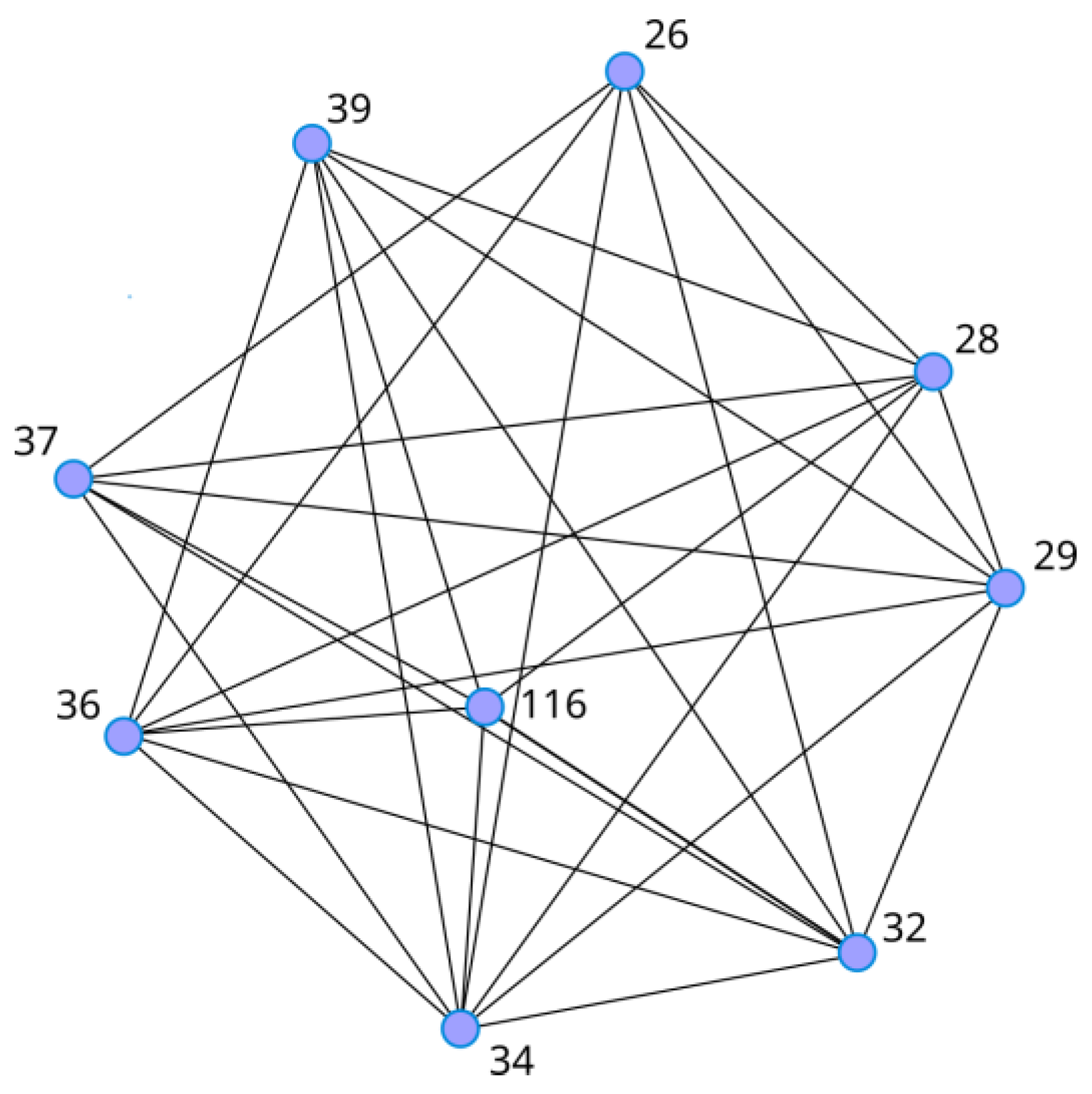
2.3. LRNTS Configuration
- available in real-time;
- homogeneous throughout the whole area of interest;
- independent of the size or the shape of a construction/exploration site;
- replicable elsewhere (other solar system bodies).
- LRNTS is a ground-based system;
- it consists of transceivers instead of transmitters;
- it is self-adjustable.
2.4. A Coordinate System, a Map Projection, and a Timeframe
3. Results
3.1. Transceiver Concept
- a pseudolite generating GNSS navigation messages, which are transmitted via a transmitting antenna;
- a GNSS receiver, which receives the signals sent by other transceivers in the network.
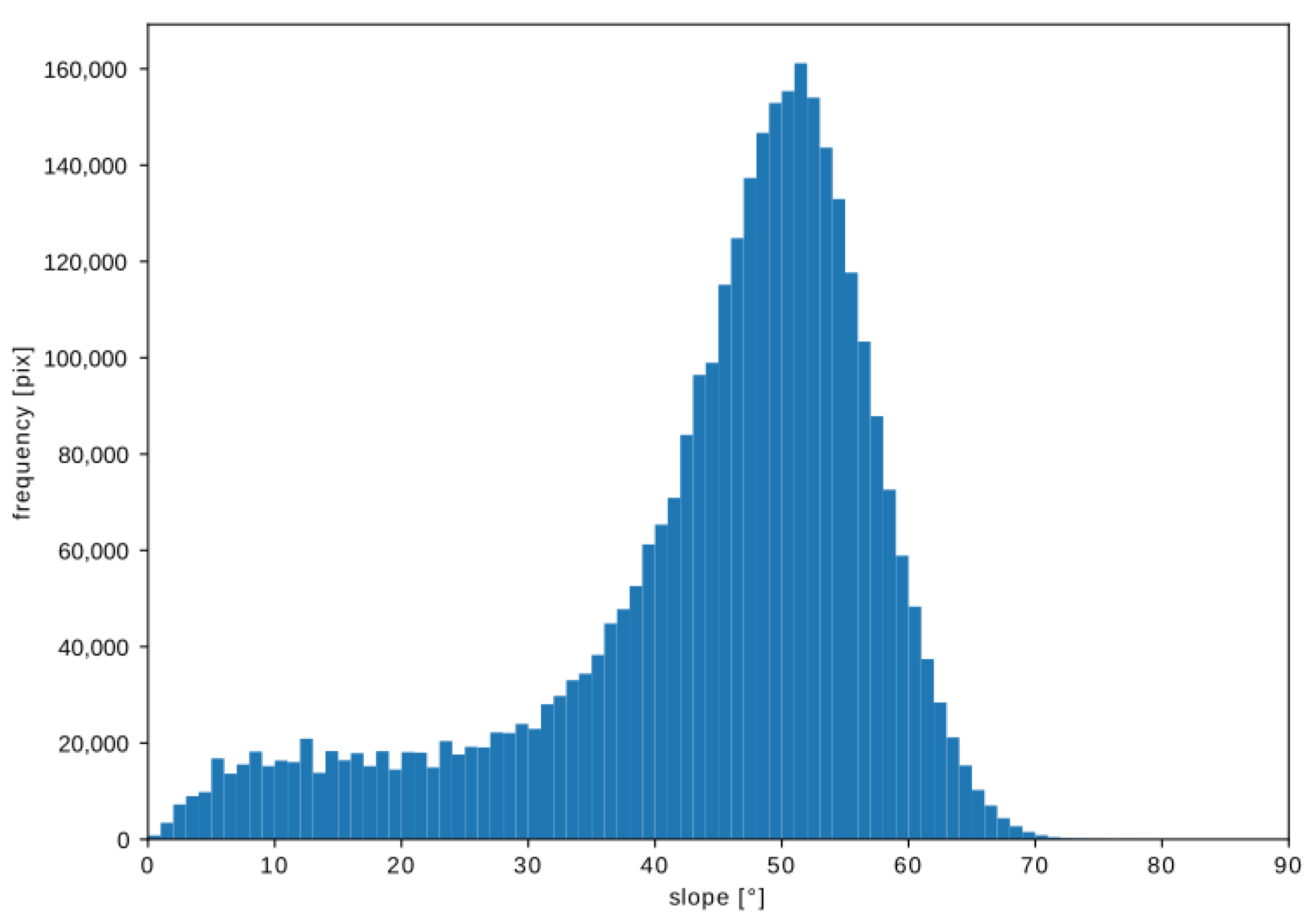
3.2. Challenges of Lunar Environmental Conditions
3.3. LRNTS Observables
- tr, ts—readings of the received and transmitted signals, respectively;
- δr, δs—biases of the receiver and the transmitter clocks, respectively;
- ρ—the geometric distance between transceivers s and r.
- Dr, Ds—hardware delays for the receiver r and the transmitter s, respectively;
- Mrs—multipath term between r and s;
- εrs—remaining random error of the measured pseudorange.
3.4. LRNTS Self-Calibration Model
- —a posteriori dispersion factor, where vector of measurement increments ;
- —corresponding element of the cofactor matrix Qx.
3.5. Simulated Configuration Setups
- enough measurands (i.e., number of transceiver nodes) for self-calibration of the system;
- signal coverage throughout (or, if not possible, for the majority of) the crater’s interior;
- reliable signal transmission by minimizing multipath effects.
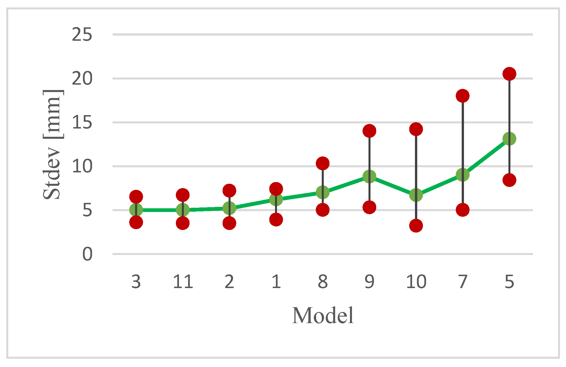
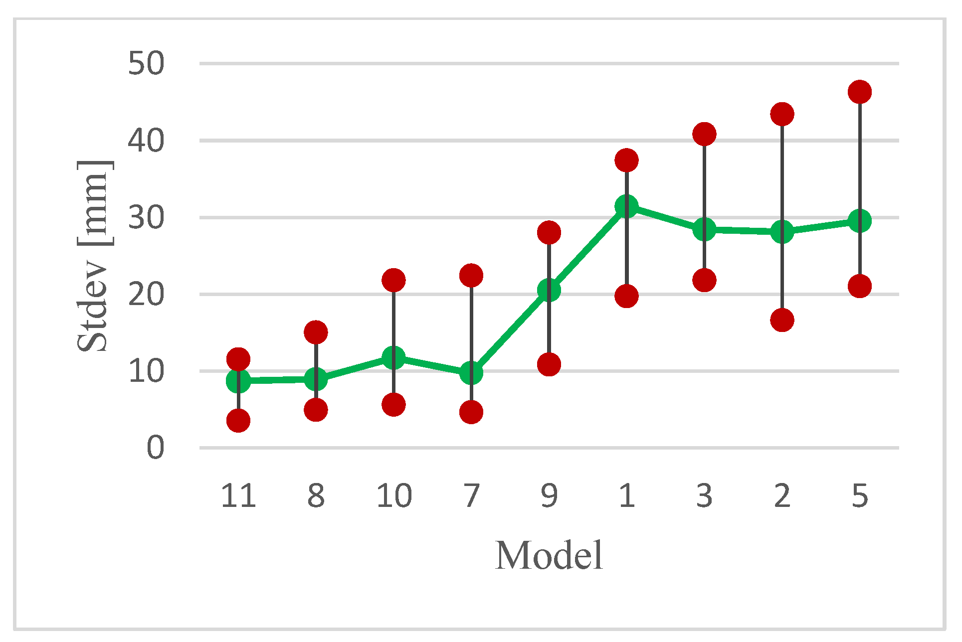
3.6. Self-Calibration
4. Discussion
- (1)
- (2)
- (3)
- efficiency expressed as the number of points and measurements (Table 1).
5. Conclusions
Author Contributions
Funding
Data Availability Statement
Acknowledgments
Conflicts of Interest
Abbreviations
| LRNTS | Lunar Regional Navigation Transceiver System |
| GNSS | Global Navigation Satellite System |
| ISRU | In Situ Resource Utilization |
| ISRO | Indian Space Research Organization |
| SLAM | Simultaneous Localization and Mapping |
| SINS | Strapdown Inertial Navigation System |
| QUEST | QUaternion ESTimator |
| SNE | Satellite Navigation Equipment |
| SCPA | Self-Calibrating Pseudolite Array |
| GPS | Global Navigation System |
| MMS | Magnetospheric Multiscale mission |
| GOES | Geostationary Operational Environmental Satellite |
| PSR | Permanently Shadowed Region |
| LRO | Lunar Reconnaissance Orbiter |
| SPA | South Pole Aitken |
| DEM | Digital Elevation Model |
| LLR | Lunar Laser Ranging |
| AFS | Atomic Frequency Standard |
| SIC | Successive Interference Calculation |
| STP | Space Time Processing |
References
- Hurst, C. China’s Rare Earth Elements Industry: What Can the West Learn? Institute for the Analysis of Global Security (IAGS). 2010. Available online: https://www.researchgate.net/publication/235080237_China’s_Rare_Earth_Elements_Industry_What_Can_the_West_Learn (accessed on 13 January 2023).
- NASA. NASA’s Lunar Exploration Program Overview. 2020. Available online: https://www.nasa.gov/sites/default/files/atoms/files/artemis_plan-20200921.pdf (accessed on 12 April 2022).
- Shekhtman, L.; Thompson, J.R. Asteroids—NASA Solar System Exploration, NASA. 2019. Available online: https://solarsystem.nasa.gov/asteroids-comets-and-meteors/asteroids/overview/?page=0&per_page=40&order=name+asc&search=&condition_1=101%3Aparent_id&condition_2=asteroid%3Abody_type%3Ailike (accessed on 14 January 2023).
- ISECG. The Global Exploration Roadmap_2022. 2022. Available online: https://www.globalspaceexploration.org/wp-content/isecg/GER_Supplement_Update_2022.pdf (accessed on 13 December 2022).
- Pittman, R.B.; Harper, L.D.; Newfield, M.E.; Rasky, D.J. Lunar Station: The Next Logical Step in Space Development. New Space 2016, 4, 7–14. [Google Scholar] [CrossRef]
- Goswami, N. India’s space program, ambitions, and activities. Asia Policy 2020, 15, 43–49. [Google Scholar] [CrossRef]
- ESA. ESA—Gateway with Orion Docked Right. 2019. Available online: https://www.esa.int/ESA_Multimedia/Images/2019/05/Gateway_with_Orion_docked_right (accessed on 15 April 2022).
- ESA. Gateway to the Moon. 2019. Available online: https://www.esa.int/Science_Exploration/Human_and_Robotic_Exploration/Gateway_to_the_Moon (accessed on 15 April 2022).
- Li, C.; Wang, C.; Wei, Y.; Lin, Y. China’s present and future lunar exploration program. Science 2019, 365, 238–239. [Google Scholar] [CrossRef]
- Clark, S. Russia Looks to China as New Space Exploration Partner. Spaceflight Now. 2021. Available online: https://spaceflightnow.com/2021/03/15/russia-looks-to-china-as-new-space-exploration-partner/ (accessed on 12 April 2022).
- Rio Tinto. What in the World Do Mining and Rocket Science Have in Common? 2019. Available online: https://www.riotinto.com/en/news/stories/mining-rocket-science-common (accessed on 6 May 2022).
- Woods, B. Caterpillar and NASA Developing Autonomous Vehicles to Mine the Moon. CNBC. 2019. Available online: https://www.cnbc.com/2019/10/23/caterpillar-and-nasa-developing-autonomous-vehicles-to-mine-the-moon.html (accessed on 6 May 2022).
- Stupar, D.I.; Ogrizović, V.; Rošer, J.; Vižintin, G. Analytical and Numerical Solution for Better Positioning in Mines with Potential Extending Application in Space Mining. Minerals 2022, 12, 640. [Google Scholar] [CrossRef]
- Liu, J.; Ren, X.; Yan, W.; Li, C.; Zhang, H.; Jia, Y.; Zeng, X.; Chen, W.; Gao, X.; Liu, D.; et al. Descent trajectory reconstruction and landing site positioning of Chang’E-4 on the lunar farside. Nat. Commun. 2019, 10, 4229. [Google Scholar] [CrossRef] [Green Version]
- Imbriale, W.A. Large Antennas of the Deep Space Network; Monograph 4 Deep—Space Communications and Navigation Series; JPL: Pasadena, CA, USA; NASA: Washington, DC, USA, 2002. [Google Scholar]
- Bilodeau, V.S.; Clerc, S.; Drai, R.; de Lafontaine, J. Optical navigation system for pin-point lunar landing. In IFAC Proceedings Volumes (IFAC-PapersOnline); IFAC: New York, NY, USA, 2014; pp. 10536–10542. [Google Scholar] [CrossRef] [Green Version]
- Ma, Y.Q.; Liu, S.C.; Sima, B.; Wen, B.; Peng, S.; Jia, Y. A precise visual localisation method for the Chinese Chang’e-4 Yutu-2 rover. Photogramm. Rec. 2020, 35, 10–39. [Google Scholar] [CrossRef]
- Schönfeldt, M.; Grenier, A.; Delépaut, A.; Swinden, R.; Giordano, P.; Ventura-Traveset, J. Across the Lunar Landscape—Exploration with GNSS Technology—Inside GNSS—Global Navigation Satellite Systems Engineering. Policy, and Design, Inside GNSS. 2020. Available online: https://insidegnss.com/across-the-lunar-landscape-exploration-with-gnss-technology/ (accessed on 6 May 2022).
- Guan, X.; Wang, X.; Fang, J.; Feng, S. An innovative high accuracy autonomous navigation method for the Mars rovers. Acta Astronaut. 2014, 104, 266–275. [Google Scholar] [CrossRef]
- Xu, F.; Fang, J. Velocity and position error compensation using strapdown inertial navigation system/celestial navigation system integration based on ensemble neural network. Aerosp. Sci. Technol. 2008, 12, 302–307. [Google Scholar] [CrossRef]
- Wei, X.; Cui, C.; Wang, G.; Wan, X. Autonomous positioning utilizing star sensor and inclinometer. Measurement 2019, 131, 132–142. [Google Scholar] [CrossRef]
- Hamera, K.E.; Mosher, T.; Gefreh, M.; Paul, R.; Slavkin, L.; Trojan, J. An evolvable lunar communication and navigation constellation architecture. In Proceedings of the 26th AIAA International Communications Satellite Systems Conference ICSSC, San Diego, CA, USA, 10–12 June 2008. [Google Scholar]
- Delépaut, A.; Giordano, P.; Ventura-Traveset, J.; Blonski, D.; Schönfeldt, M.; Schoonejans, P.; Aziz, S.; Walker, R. Use of GNSS for lunar missions and plans for lunar in-orbit development. Adv. Space Res. 2020, 66, 2739–2756. [Google Scholar] [CrossRef]
- Mikrin, E.A.; Mikhailov, M.V.; Orlovskii, I.V.; Rozhkov, S.N.; Krasnopol’skii, I.A. Satellite Navigation of Lunar Orbiting Spacecraft and Objects on the Lunar Surface. Gyroscopy Navig. 2019, 10, 54–61. [Google Scholar] [CrossRef]
- LeMaster, E.A. Self Calibrating Pseudolite Arrays—Theory and Experiment. Master’s Thesis, Stanford University, Stanford CA, USA, 2002. Available online: https://web.stanford.edu/group/arl/cgi-bin/drupal/sites/default/files/public/publications/LeMaster%202002.pdf (accessed on 27 February 2023).
- Lemaster, E.A.; Rock, S.M. A Local-Area GPS Pseudolite-Based Mars Navigation System. In Proceedings of the IEEE 10th International Conference on Advanced Robotics, Budapest, Hungary, 22–25 August 2001. [Google Scholar]
- Stone, J.M.; LeMaster, E.A.; David Powell, J.; Rock, S. GPS Pseudolite Transceivers and their Applications. In Proceedings of the 1999 National Technical Meeting of the Institute of Navigation, San Diego, CA, USA, 25–27 January 1999. [Google Scholar]
- Cobb, H.S. GPS Pseudolites: Theory, Design, and Applications. 1997. Available online: https://web.stanford.edu/group/scpnt/gpslab/pubs/theses/StewartCobbThesis97.pdf (accessed on 26 February 2023).
- Jenner, L. NASA Eyes GPS at the Moon for Artemis Missions. NASA Space Technology. 2019. Available online: http://www.nasa.gov/feature/goddard/2019/nasa-eyes-gps-at-the-moon-for-artemis-missions (accessed on 1 May 2022).
- HAKUTO-R Mission 1|ispace. Available online: https://ispace-inc.com/m1 (accessed on 17 January 2023).
- NASA: Artemis, I. Available online: https://www.nasa.gov/specials/artemis-i/ (accessed on 26 February 2023).
- ESA—Moonlight. Available online: https://www.esa.int/Applications/Telecommunications_Integrated_Applications/Moonlight (accessed on 26 February 2023).
- Baird, D. NASA Mirrors on ESA Pathfinder to Enhance Lunar Navigation. 2022. Available online: http://www.nasa.gov/feature/goddard/2022/nasa-mirrors-on-esa-pathfinder-to-enhance-lunar-navigation (accessed on 26 February 2023).
- CSCEM. The Scientific Context for Exploration of the Moon; National Academies Press: Washington, DC, USA, 2007. [Google Scholar] [CrossRef]
- Mitchell, J.; Lawrence, S.; Robinson, M.; Speyerer, E.; Denevi, B. Using complementary remote sensing techniques to assess the presence of volatiles at the lunar north pole. Planet. Space Sci. 2018, 162, 133–147. [Google Scholar] [CrossRef]
- Mazarico, E.; Neumann, G.A.; Smith, D.E.; Zuber, M.T.; Torrence, M.H. Illumination conditions of the lunar polar regions using LOLA topography. Icarus 2011, 211, 1066–1081. [Google Scholar] [CrossRef]
- Bussey, D.B.J.; Spudis, P.D.; Robinson, M.S. Illumination conditions at the lunar South Pole. Geophys. Res. Lett. 1999, 26, 1187–1190. [Google Scholar] [CrossRef] [Green Version]
- Wingo, D. Site Selection for Lunar Industrialization, Economic Development, and Settlement. New Space 2016, 4, 19–39. [Google Scholar] [CrossRef]
- Zuber, M.T.; Head, J.W.; Smith, D.E.; Neumann, G.A.; Mazarico, E.; Torrence, M.H.; Aharonson, O.; Tye, A.R.; Fassett, C.I.; Rosenburg, M.A.; et al. Constraints on the volatile distribution within Shackleton crater at the lunar south pole. Nature 2012, 486, 378–381. [Google Scholar] [CrossRef] [Green Version]
- Vanoutryve, B.; de Rosa, D.; Fisackerly, R.; Houdou, B.; Carpenter, J.; Philippe, C.; Pradier, A.; Jojaghaian, A.; Espinasse, S.; Gardini, B. An Analasys of Illumionation and Communication Conditions near Lunar South Pole Based on Kaguya Data; ESA: Paris, France, 2010. [Google Scholar]
- Barker, M.K.; Mazarico, E.; Neumann, G.A.; Zuber, M.T.; Haruyama, J.; Smith, D.E. A new lunar digital elevation model from the Lunar Orbiter Laser Altimeter and SELENE Terrain Camera. Icarus 2016, 273, 346–355. [Google Scholar] [CrossRef] [Green Version]
- Kokhanov, A.A.; Karachevtseva, I.P.; Zubarev, A.E.; Patraty, V.; Rodionova, Z.F.; Oberst, J. Mapping of potential lunar landing areas using LRO and SELENE data. Planet. Space Sci. 2017, 162, 179–189. [Google Scholar] [CrossRef]
- Basilevsky, A.T.; Krasilnikov, S.S.; Ivanov, M.A.; Malenkov, M.I.; Michael, G.G.; Liu, T.; Head, J.W.; Scott, D.R.; Lark, L. Potential Lunar Base on Mons Malapert: Topographic, Geologic and Trafficability Considerations. Sol. Syst. Res. 2019, 53, 383–398. [Google Scholar] [CrossRef]
- Mahoney, E. (Ed.) The Global Exploration Roadmap Supplement Octobar; NASA: Washington, DC, USA, 2022. Available online: https://www.nasa.gov/sites/default/files/atoms/files/ger-supplement-update-2022-final-10-6-22_tagged.pdf (accessed on 11 December 2022).
- Ludivig, P.; Olivares-mendez, M.; Diaz, A.C.; Ivanov, D.; Voos, H.; Lamamy, J. Testing Environments for Lunar Surface Perception Systems; Combining Indoor Facilities, Virtual Environments and Analogue Field Tests. In Proceedings of the I-SAIRAS 2020, Pasadena, CA, USA, 19–23 October 2020. [Google Scholar]
- Sherwood, B. Principles for a practical Moon base. Acta Astronaut. 2019, 160, 116–124. [Google Scholar] [CrossRef]
- Powering the Moon: Designing a Microgrid for Future Lunar Base. 2022. Available online: https://phys.org/news/2022-05-powering-moon-microgrid-future-lunar-1.html (accessed on 11 December 2022).
- LOLA, S.T. Moon LRO LOLA DEM 118m v1|USGS Astrogeology Science Center. 2014. Available online: https://astrogeology.usgs.gov/search/details/Moon/LRO/LOLA/Lunar_LRO_LOLA_Global_LDEM_118m_Mar2014/cub (accessed on 6 May 2021).
- Williams, J.G.; Boggs, D.H.; Folkner, W.M. DE430 Lunar Orbit, Physical Librations, and Surface Coordinates; Jet Propulsion Laboratory: Pasadena, CA, USA, 2013; pp. 1–19. [Google Scholar] [CrossRef]
- Folkner, W.M.; Williams, J.G.; Boggs, D.H.; Park, R.S.; Kuchynka, P. The Planetary and Lunar Ephemerides DE430 and DE431. Interplanet. Netw. Prog. Rep. 2014, 196, 42–196. [Google Scholar]
- Chowdhury, D.D. NextGen Network Synchronization; Springer: Berlin/Heidelberg, Germany, 2021. [Google Scholar] [CrossRef]
- Martinez, F.J.G. Performance of New GNSS Satellite Clocks; KIT Scientific Publishing: Karlsruhe, Germany, 2014. [Google Scholar] [CrossRef]
- Madhani, P.H.; Axelrad, P.; Krumvieda, K.; Thomas, J. Application of successive interference cancellation to the GPS pseudolite near-far problem. IEEE Trans. Aerosp. Electron. Syst. 2003, 39, 481–488. [Google Scholar] [CrossRef] [Green Version]
- Martin, S.; Kuhlen, H.; Abt, T. Interference and regulatory aspects of GNSS pseudolites. In Proceedings of the 18th International Technical Meeting of the Satellite Division of the Institute of Navigation, ION GNSS 2005, Long Beach, CA, USA, 13–16 September 2005. [Google Scholar] [CrossRef] [Green Version]
- Chang, C.L.; Juang, J.C. Performance analysis of narrowband interference mitigation and near-far resistance scheme for GNSS receivers. Signal Process. 2010, 90, 2676–2685. [Google Scholar] [CrossRef]
- Marathe, T.; Daneshmand, S.; Lachapelle, G. Pseudolite interference mitigation and signal enhancements using an antenna array. In Proceedings of the 2015 International Conference on Indoor Positioning and Indoor Navigation, IPIN 2015, Banff, AB, Canada, 13–16 October 2015. [Google Scholar] [CrossRef]
- Zheng, Z.H.; Wang, B.; Zhou, Z.Q.; Gao, Z.F. A scene matching method for automatic and precise soft landing on the lunar surface. Beijing Ligong Daxue Xuebao/Trans. Beijing Inst. Technol. 2013, 33, 172–177. [Google Scholar]
- Remesh, N.; Ramanan, R.V.; Lalithambika, V.R. A Novel Indirect Scheme for Optimal Lunar Soft Landing at a Target Site. J. Inst. Eng. Ser. C 2021, 102, 1379–1393. [Google Scholar] [CrossRef]
- Hu, T.; He, L.; Cao, T.; Zhang, H.; Hu, Y.; Qian, Z. Autonomous Obstacle Detection and Avoidance of Lunar Landing Based on Active and Passive Sensors. In Proceedings of the 2021 International Symposium on Computer Science and Intelligent Controls, ISCSIC 2021, Rome, Italy, 12–14 November 2021. [Google Scholar] [CrossRef]
- Wong, U.H.; Wu, Y.; Wong, H.C.; Liang, Y.; Tang, Z. Modeling the reflectance of the lunar regolith by a new method combining Monte Carlo ray tracing and Hapke’s model with application to chang’e-1 IIM data. Sci. World J. 2014, 2014, 457138. [Google Scholar] [CrossRef] [PubMed] [Green Version]
- Petrova, E.V.; Markiewicz, W.J.; Keller, H.U. Regolith Surface Reflectance: A New Attempt to Model. Sol. Syst. Res. 2001, 35, 278–290. [Google Scholar] [CrossRef]
- Heiken, G.H.; Vaniman, D.T.; French, B.M. Lunar Sourcebook: A User’s Guide to the Moon; Cambridge University Press: Cambridge, UK, 1991. [Google Scholar]
- Gaier, J.R. The Effects of Lunar Dust on EVA Systems during the Apollo Missions. 2005. Available online: http://www.sti.nasa.gov (accessed on 11 December 2022).
- Budzyń, D.; Zare-Behtash, H.; Cowley, A.; Cammarano, A. Implicit lunar dust mitigation technology: Compliant mechanisms. Acta Astronaut. 2023, 203, 146–156. [Google Scholar] [CrossRef]
- Budzyń, D.; Tuohy, E.; Garrivier, N.; Schild, T.; Cowley, A.; Cruise, R.; Adachi, M.; Zare-Behtash, H.; Cammarano, A. Lunar Dust: Its Impact on Hardware and Mitigation Technologies. In Proceedings of the 46th Aerospace Mechanisms Symposium, Houston, TX, USA, 11–13 May 2022. [Google Scholar]
- Climent, B.; Torroba, O.; González-Cinca, R.; Ramachandran, N.; Griffin, M.D. Heat storage and electricity generation in the Moon during the lunar night. Acta Astronaut. 2014, 93, 352–358. [Google Scholar] [CrossRef]
- Ulamec, S.; Biele, J.; Trollope, E. How to survive a Lunar night. Planet. Space Sci. 2010, 58, 1985–1995. [Google Scholar] [CrossRef]
- Hofmann-Wellenhof, E.; Lichtenegger, B.; Wasle, H. Observables. In GNSS—Global Navigation Satellite Systems; Springer Vienna: Vienna, Austria, 2007; pp. 105–160. [Google Scholar] [CrossRef]


| Map Model No. | Number of Points | Number of Measurements | Number of Unknowns | % of Signal Availability |
|---|---|---|---|---|
| 1 | 6 | 58 | 18 | 91.6 |
| 2 | 8 | 102 | 24 | 95.7 |
| 3 | 10 | 162 | 30 | 98.6 |
| 4 | 6 | 52 | 18 | 84.0 |
| 5 | 8 | 102 | 24 | 95.3 |
| 6 | 10 | 152 | 30 | 96.3 |
| 7 | 7 | 48 | 21 | 78.4 |
| 8 | 7 | 60 | 21 | 86.8 |
| 9 | 8 | 82 | 24 | 92.8 |
| 10 | 7 | 64 | 21 | 91.2 |
| 11 | 9 | 134 | 27 | 95.5 |
| 12 | 11 | 188 | 33 | 96.4 |
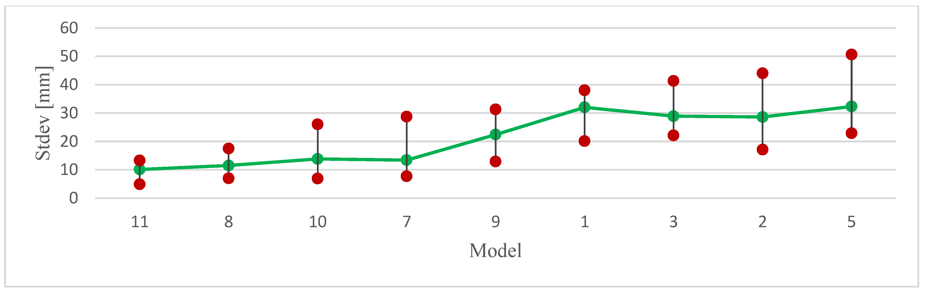
| Map Model | (3D) σxyz (Min) | (3D) σxyz (Max) | (2D) σxy (Min) | (2D) σxy (Max) | (1D) σz (Min) | (1D) σz (Max) |
|---|---|---|---|---|---|---|
| (N°) | (mm) | (mm) | (mm) | (mm) | (mm) | (mm) |
| 1 | 20.1 | 38.0 | 3.9 | 7.4 | 19.7 | 37.4 |
| 2 | 17.1 | 44.0 | 3.5 | 7.2 | 16.6 | 43.4 |
| 3 | 22.1 | 41.3 | 3.6 | 6.5 | 21.8 | 40.8 |
| 4 | 41.3 | 283.3 | 15.7 | 151.1 | 38.2 | 239.6 |
| 5 | 22.9 | 50.6 | 8.4 | 20.5 | 21.0 | 46.3 |
| 6 | 24.1 | 332.5 | 11.6 | 167 | 19.0 | 287.5 |
| 7 | 7.7 | 28.7 | 5.0 | 18.0 | 4.6 | 22.4 |
| 8 | 7.0 | 17.5 | 5.0 | 10.3 | 4.9 | 15.0 |
| 9 | 12.9 | 31.3 | 5.3 | 14.0 | 10.8 | 28.0 |
| 10 | 6.9 | 26.0 | 3.2 | 14.2 | 5.6 | 21.8 |
| 11 | 4.9 | 13.3 | 3.5 | 6.7 | 3.5 | 11.5 |
| 12 | 11.8 | 336.8 | 7.6 | 169.2 | 9.0 | 291.2 |
Disclaimer/Publisher’s Note: The statements, opinions and data contained in all publications are solely those of the individual author(s) and contributor(s) and not of MDPI and/or the editor(s). MDPI and/or the editor(s) disclaim responsibility for any injury to people or property resulting from any ideas, methods, instructions or products referred to in the content. |
© 2023 by the authors. Licensee MDPI, Basel, Switzerland. This article is an open access article distributed under the terms and conditions of the Creative Commons Attribution (CC BY) license (https://creativecommons.org/licenses/by/4.0/).
Share and Cite
Ignjatović Stupar, D.; Ogrizović, V.; Rošer, J.; Poslončec-Petrić, V.; Vižintin, G. Conceptual Navigation and Positioning Solution for the Upcoming Lunar Mining and Settlement Missions Based on the Earth’s Mining Experiences: Lunar Regional Navigation Transceiver System. Minerals 2023, 13, 371. https://0-doi-org.brum.beds.ac.uk/10.3390/min13030371
Ignjatović Stupar D, Ogrizović V, Rošer J, Poslončec-Petrić V, Vižintin G. Conceptual Navigation and Positioning Solution for the Upcoming Lunar Mining and Settlement Missions Based on the Earth’s Mining Experiences: Lunar Regional Navigation Transceiver System. Minerals. 2023; 13(3):371. https://0-doi-org.brum.beds.ac.uk/10.3390/min13030371
Chicago/Turabian StyleIgnjatović Stupar, Danijela, Vukan Ogrizović, Janez Rošer, Vesna Poslončec-Petrić, and Goran Vižintin. 2023. "Conceptual Navigation and Positioning Solution for the Upcoming Lunar Mining and Settlement Missions Based on the Earth’s Mining Experiences: Lunar Regional Navigation Transceiver System" Minerals 13, no. 3: 371. https://0-doi-org.brum.beds.ac.uk/10.3390/min13030371