Article

Design of a 3D-Printed Hand Exoskeleton Based on Force-Myography Control for Assistance and Rehabilitation

1
Department of Electrical Engineering and Information Technologies, Polytechnic and Basic Sciences School, University of Naples “Federico II”, 80125 Naples, Italy
2
Department of Industrial Engineering, Polytechnic and Basic Sciences School, University of Naples “Federico II”, 80125 Naples, Italy
3
School of Engineering, Design and Built Environment, Western Sydney University, Penrith 2747, Australia
4
The Adelaide Institute for Sleep Health, Flinders University, Bedford Park 5042, Australia
*
Authors to whom correspondence should be addressed.
Submission received: 6 December 2021 / Revised: 28 December 2021 / Accepted: 8 January 2022 / Published: 13 January 2022
(This article belongs to the Special Issue Feature Papers to Celebrate the First Impact Factor of Machines)

Abstract

:
Voluntary hand movements are usually impaired after a cerebral stroke, affecting millions of people per year worldwide. Recently, the use of hand exoskeletons for assistance and motor rehabilitation has become increasingly widespread. This study presents a novel hand exoskeleton, designed to be low cost, wearable, easily adaptable and suitable for home use. Most of the components of the exoskeleton are 3D printed, allowing for easy replication, customization and maintenance at a low cost. A strongly underactuated mechanical system allows one to synergically move the four fingers by means of a single actuator through a rigid transmission, while the thumb is kept in an adduction or abduction position. The exoskeleton’s ability to extend a typical hypertonic paretic hand of stroke patients was firstly tested using the SimScape Multibody simulation environment; this helped in the choice of a proper electric actuator. Force-myography was used instead of the standard electromyography to voluntarily control the exoskeleton with more simplicity. The user can activate the flexion/extension of the exoskeleton by a weak contraction of two antagonist muscles. A symmetrical master–slave motion strategy (i.e., the paretic hand motion is activated by the healthy hand) is also available for patients with severe muscle atrophy. An inexpensive microcontroller board was used to implement the electronic control of the exoskeleton and provide feedback to the user. The entire exoskeleton including batteries can be worn on the patient’s arm. The ability to provide a fluid and safe grip, like that of a healthy hand, was verified through kinematic analyses obtained by processing high-framerate videos. The trajectories described by the phalanges of the natural and the exoskeleton finger were compared by means of cross-correlation coefficients; a similarity of about 80% was found. The time required for both closing and opening of the hand exoskeleton was about 0.9 s. A rigid cylindric handlebar containing a load cell measured an average power grasp force of 94.61 N, enough to assist the user in performing most of the activities of daily living. The exoskeleton can be used as an aid and to promote motor function recovery during patient’s neurorehabilitation therapy.

1. Introduction

The human hand is the most dexterous part of human body [1,2,3] and enables people to interact with the external environment, including the activities of daily living (ADL). Voluntary hand movement control is typically impaired after a cerebral stroke, also known as a cerebral vascular accident (CVA), which is one of the main causes of motor disability, with an incidence of 15 million people worldwide per year [4]. More than 40% of stroke survivors suffer from chronic contralateral upper limb hemiparesis [5]. To date, motor impairment following stroke is believed to be a direct consequence of lesions of the motor cortex [6]. One of the most common deficits is the loss of hand function, in particular finger extension [7]. Many patients after stroke are affected by an initial flaccid paresis, replaced by hypertonia, spasticity and abnormal synergy in finger flexors, and weakness in finger extensors, leading to loss of voluntary movement control and hyperflexion [8,9,10,11], which severely restrict the ability to open their hand. Indeed, it has been shown that post-stroke patients experience a decrease of 82% in their grip force and of 88% in their finger extension [12], resulting in a typical clenched hand position [13]. Another study showed that the grip force of post-stroke patients with different severities of hemiparesis was 112 N ± 72 N, reduced by about 75% with respect to healthy subjects (441 N ± 124 N) [14]. In addition, a 17% reduction in extrinsic extensor muscles has been reported if the hand is not used over time, due to the onset of atrophy or degradation [12]. This condition affects the quality of life of post-stroke subjects, limiting their autonomy in carrying out everyday activities. Neuroplasticity is the underlying mechanism for the recovery of motor functions after stroke, defined as the ability of the brain to reorganize itself [15]. Neurons linked to the damaged area are potentially able to gradually replace the impaired functions with a higher connectivity level [16]. Therefore, rehabilitation therapy after stroke is properly referred to as neurorehabilitation. Studies have shown that stroke patients benefit from performing intensive training sessions of repetitive and task-specific movements with the impaired limb, in order to induce cortical reorganization, which is responsible for regaining motor control of the affected area. In this way, patients strengthen their motor learning and can improve or recover impaired motor functions [15,17,18].
In the last few decades, research on motor rehabilitation after stroke has focused on robot-assisted strategies [19]. In this scenario, the use of exoskeletons has gained attention. In particular, wearable devices increase the effectiveness of rehabilitation therapy, which can be performed at home in longer and more intensive sessions, provide more rapid improvement and also reduce healthcare costs [3]. Furthermore, patients are more motivated because they are actively involved in the rehabilitation process, unlike traditional therapy that consists in the passive execution of movements with the help of a therapist.
A review by du Plessis et al. [20] offers an overview of active hand exoskeletons categorized according to three main criteria: design type (e.g., rigid or soft), purpose (e.g., assistive, rehabilitation, haptic or augmentation purposes) and design requirements (e.g., safety, comfort, affordability and adaptability). A more detailed classification considers the type of actuation (e.g., electrical motors, pneumatics, series elastic actuators, hydraulics), power transmission (e.g., mechanical links, gears, cables), sensing (e.g., potentiometers, encoders, EMG, EEG, force sensors) and control method (e.g., high-level, low-level continuous passive motion, master/slave). In particular, as shown in the literature, electromyography (EMG) is by far the most used technique for providing control to human–machine interfaces, including hand exoskeletons [19,20]. However, different issues are related to the use of EMG, such as: the need for electrodes and stable electrical contact; physiological cross-talk with other EMG signals from near muscles; electromagnetic interferences; demanding processing to obtain a suitable control signal (e.g., the EMG linear envelope (EMG-LE) proportional to the developed muscle strength) [21,22,23]. A previous study showed the high similarity between the EMG-LE and the signal obtainable from a custom force sensor capable of detecting the mechanical activity of muscles (referred to as force-myography (FMG)) [24]. The advantages deriving from the use of FMG instead of EMG are various [25]: the problems related to EMG recording and its processing are avoided; the force sensor output can be used as is (no processing is required) and has already been successfully demonstrated for various applications (hand prosthesis control [26,27,28,29]; hand gesture recognition [30,31]; physiological parameters monitoring [32,33,34]); moreover, a very recent study suggests that force sensors seem to perform better than EMG in daily activities for exoskeleton controls [35].
Different hand exoskeletal systems have been proposed for hand rehabilitation and assistance. Randazzo et al. presented “mano”, a wearable hand exoskeleton, designed to assist and restore hand functions of people with motor disabilities [36], controlled via a brain–computer interface (BCI). Araujo et al. presented Hand Exoskeleton for Rehabilitation Objective (HERO), for the recovery of extension and flexion movements of the fingers in post-stroke patients [37], controlled by a motor imagery BCI. Wege and Zimmermann presented a hand exoskeleton for rehabilitation purposes [38], controlled via 10-channel EMG on the patient’s forearm. Ho et al. exploited EMG to drive a hand exoskeleton for rehabilitation purposes in chronic post-stroke patients [39]. Dwivedi et al. proposed a soft assistive exoskeleton controlled via a muscle–machine interface, consisting of a sleeve with three EMG and five force sensors [40].
Although the rehabilitation is maximized by repetitive and active use of the paretic limb alone, for many stroke survivors the degree of hemiparesis is so severe that they are unable to perform any motor control of that limb. A review by Carson showed that bilateral movement training appears to enhance neural activity in the stroke-affected cortex and to improve the hemiplegic arm functions in both acute and chronic stroke survivors. Indeed, the muscle contraction of the heathy arm leads to an increase in the excitability of the homologous motor pathways of the paretic arm. This phenomenon, known as “motor irradiation”, can be demonstrated in different ways, including EMG activity registered in the paretic arm while the opposite healthy arm is contracting. According to this theory, the bilateral training induces the reorganization of cortical networks thanks to brain plasticity [41]. Compared to unilateral training, patients who have performed bilateral training appear to achieve improvements in upper limb function and decreased movement time of the impaired limb [42]. Different studies presented assistive/rehabilitative hand exoskeletons based on a master/slave motion strategy, in which the user’s healthy hand on the master side provides the motion trigger for the impaired hand on the slave side. As an example, Loconsole et al. proposed the BRAVO Hand exoskeleton system to support post-stroke patients in cylindrical grasping tasks, using the bilateral grasp technique [43], controlled via EMG. A complex hand rehabilitation system with 18 DOF was developed by Ueki et al. [44], controlled via a glove equipped with 3D motion sensors. Rahman and Al-Jumaily [16] proposed a hand rehabilitation exoskeleton, controlled via a glove equipped with flex sensors. Cortese et al. [45] proposed hand telerehabilitation system, in which the therapist wears a glove equipped with accelerometers (master), while the patient wears the exoskeleton (slave).
The current study aims to present a novel hand exoskeleton for assistance and rehabilitation of subjects with neuromotor diseases (i.e., post-stroke patients). While most exoskeletons use EMG signals or inertial sensors as control signals, the proposed one uses FMG sensors capable of detecting the mechanical activity of muscles. The device is designed to actively control finger flexion/extension and to be low cost, 3D printable, fully wearable, lightweight, portable, suitable for home use and enabled for master/slave techniques.

2. Materials and Methods

2.1. Design Requirements

The following specifications were considered for the hand exoskeleton design:
  • As many pieces as possible should be made with 3D printing to allow simple low-cost reproduction, affordable maintenance and easier customization/modification.
  • The exoskeletal structure should contact the back of the hand, in order to free the palm and fingers so as to preserve a more natural grip of objects [36]. In this way, the mechanical system is strongly underactuated [46], but it still provides a comfortable grasp, without the need for complex controls [36].
  • The torque exerted by the actuator should be capable of extending a paretic hand, which generally tends to be clenched due to muscle spasticity [10].
  • The user should be able to activate both the flexion and extension of the hand by using a force-myography control system [47].

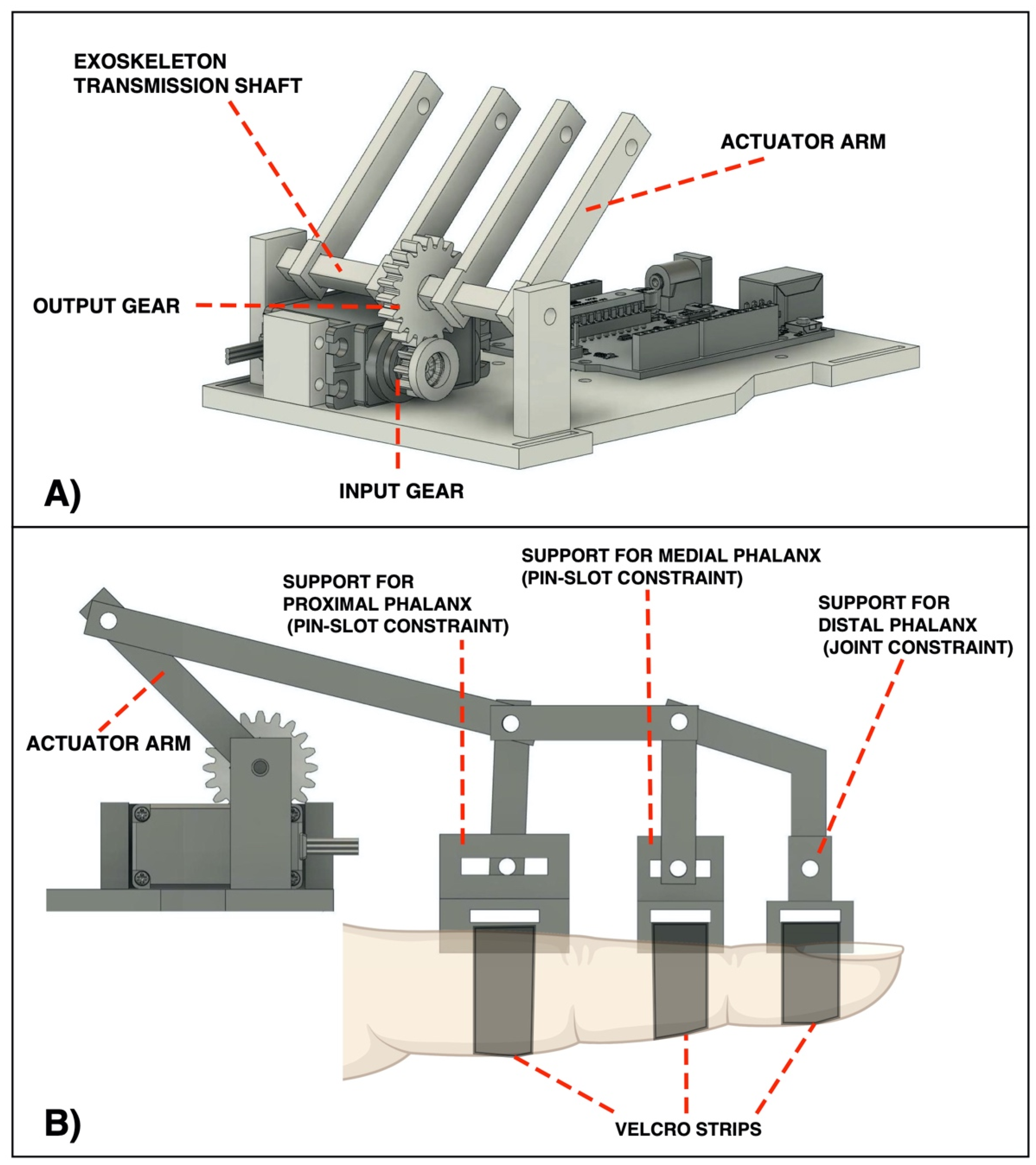
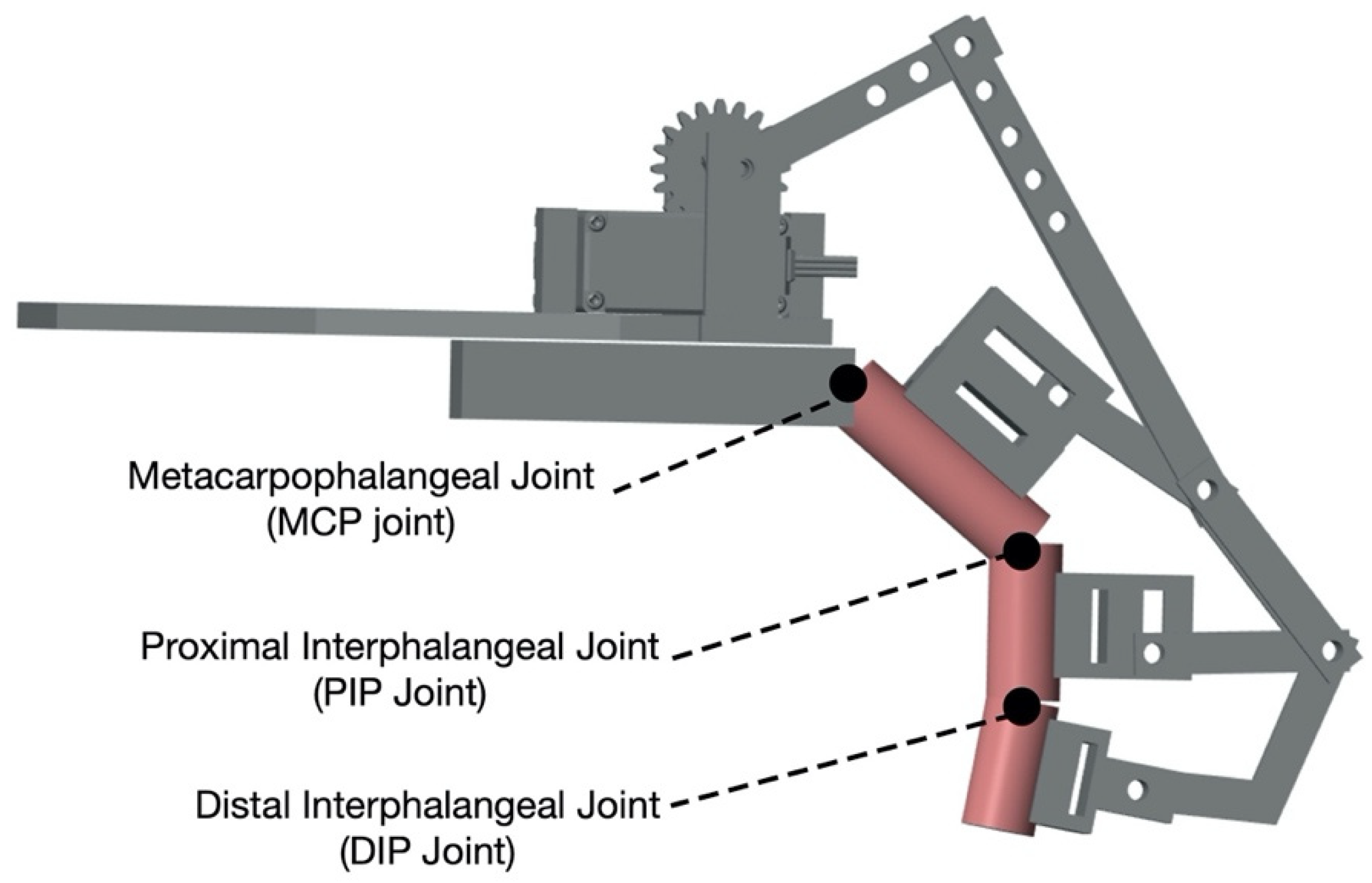
2.2. Hand Exoskeleton Design

The hand exoskeleton was designed with Autodesk Fusion 360 [48] (CAD files are provided as Supplementary Materials) and most of the components were realized in PLA with a 3D printer (Dreamer NX, FlashForge 3D Technology, Jinhua, China). Figure 1 shows the rigid platform (shaped to the size of an adult man’s left hand) which is bound on the back of the hand by means of Velcro strips, passed through specific holes. The platform has a housing for the actuator and for an Arduino UNO board [49]. The thumb is bound to a rigid structure in order to keep it in an adduction position or, alternatively, in abduction. Index, middle and ring fingers are provided with supports for each phalanx; in detail, the supports for the proximal and medial phalanx have a pin-slot constraint, while the support for the distal phalanx has a joint constraint. Only the little finger is provided with a pin-slot constraint support for the proximal phalanx and a joint constraint support for the distal phalanx. The pin-slot constraints have the purpose of increasing the roto-translation of the mechanical system for each finger. The device can be easily adapted to a right hand by swapping the index and little finger supports and placing the fixed thumb support on the opposite symmetrical side.
Figure 2 shows that a single 270-degree servomotor is used to transmit motion to all fingers of the exoskeleton. The choice of the minimum torque of the servomotor was carried out through SimScape Multibody [50] simulations (see the Results for details). An input gear (Ninput = 10 teeth) superimposed on the servomotor output shaft is coupled with an output gear (Noutput = 20 teeth), in order to increase the torque, but at the same time ensuring an adequate angular excursion to the transmission shaft. The transmission ratio R of the gear train, also known as mechanical advantage (MA), is defined as the gear teeth ratio (Noutput/Ninput) or the torque ratio (Toutput/Tinput) and is equal to 2, according to the following formula:
R = N output N input = 20 10 = T output T input = MA = 2
Consequently, the angular excursion of the transmission shaft is 135 degrees (i.e., 270 degrees divided by 2). For each finger, an actuator arm is rigidly connected to the transmission shaft to transfer the motion to the fingers.

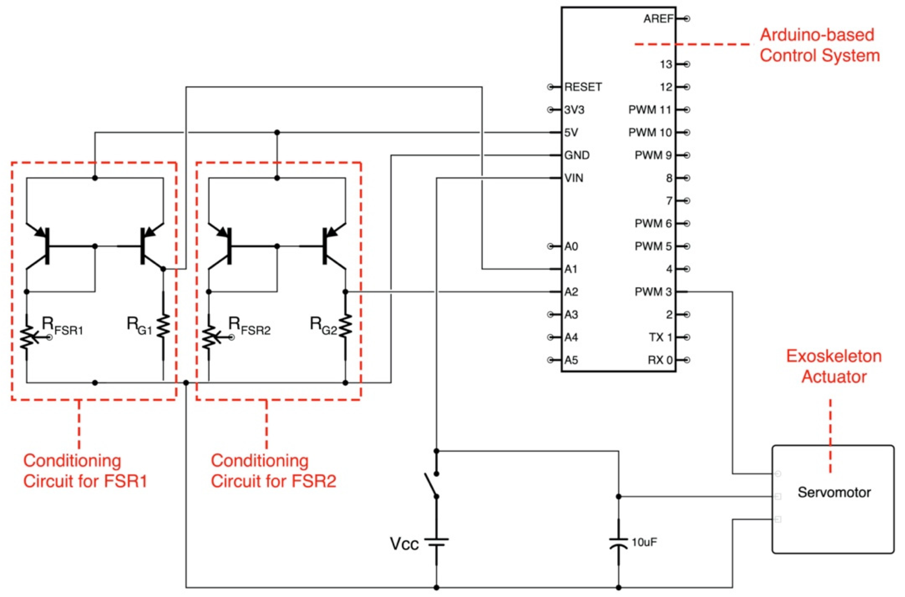
2.3. Control System Based on Force-Myography

The sensorized armband presented in a previous study [30], equipped with custom force-sensitive resistor (FSR) sensors able to provide FMG signals, was used to control the exoskeleton. FMG signals were recorded from two antagonist forearm muscles: the flexor carpi ulnaris (involved in finger flexion) and the extensor digitorum (involved in finger extension).
Each FSR-based sensor is conditioned by means of a current mirror circuit, realized by means of a pair of pnp BJT (2N2907). The circuit replicates the FSR current in the gain resistor (see Figure 3), providing an output voltage that is directly proportional to the force exerted on the sensor [30].
The exoskeleton control is implemented by a low-cost Arduino board. The whole system is powered by a 7.4 V battery pack (2 × 3.7 V, 3000 mAh). Every time the hand exoskeleton is worn (the average time required is about 2 min), the user is guided in a calibration phase by the LCD Shield connected to the Arduino UNO board. In this phase, the preload of the force sensors and the maximum amplitudes of the signals coming from the two forearm muscles are evaluated. After the calibration process, the hand exoskeleton is ready to work. Figure 4 shows in panel A the hand exoskeleton and related components necessary for its operation, while panel B depicts the positioning of the two FSR-based sensors (embedded in the FMG armband) on the flexor carpi ulnaris and the extensor digitorum, respectively.
The algorithm implemented in the Arduino board allows both on–off and proportional control of the exoskeleton motion. The actual operation mode can be suggested by the neurorehabilitator and/or selected by the patient himself. Figure 5 shows, as an example, some positions assumed by the exoskeleton.
However, if the patient has developed a severe muscle atrophy, the FMG signals could be very low, sometimes unusable. In this case it is preferable to configure the system in another mode and use the “symmetrical master–slave motion strategy” as in [16,43,44,45]. The user’s healthy hand (master) activates the motion of the paretic hand (slave), as sketched in Figure 6.

2.4. Hand Exoskeleton Setup in the Simulation Environment

Figure 7 shows the model created with SimScape Multibody software, to simulate the operation of the exoskeleton. The phalanges were modeled as cylinders of various lengths (inspired by the size of an adult hand: proximal phalange of 50 mm; medial phalange of 30 mm; distal phalange of 25 mm) connected to each other by joint constraints, representing the metacarpophalangeal (MCP), proximal interphalangeal (PIP) and distal interphalangeal (DIP) joints. The phalanges and the related supports are rigidly coupled (no sliding between support and phalanx is allowed).
The closing force of the four fingers is modeled by a single spring exerting an elastic force of about 200 N (elastic modulus K = 200/11 N/cm), in order to simulate the typical clenched fist position of a paretic hand.
The purpose of the simulation is to estimate the torque required by the actuator to bring the fingers into the extension condition and overcome the opposing forces which tend to close the hand. By considering a hand closing force of about 200 N (higher than the mean grip forces of paretic hands showed in [14,51]), a precautionary oversizing of the required actuator torque is obtained.
The simulation consists of the following steps: at the start (t = 0 s), the finger is fully extended; by activating the spring force, the finger moves into the flexed position (t ≃ 0.012 s); then, the servomotor is powered (t = 0.05 s) and brings the finger back to the extended position (t ≃ 1.03 s).

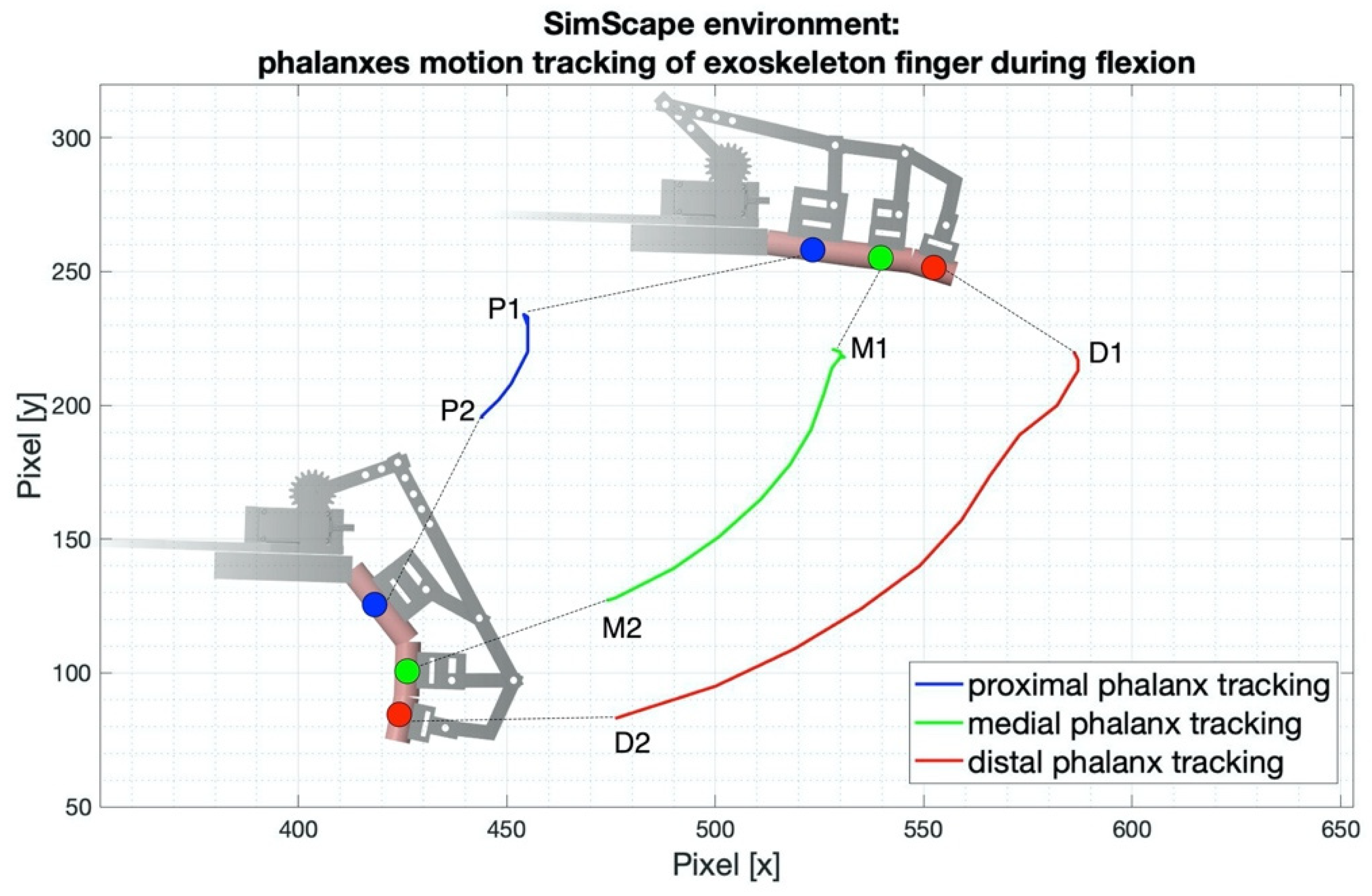
2.5. Kinematics Evaluation

A test was performed to evaluate the kinematics of the exoskeleton [37]. Videos were recorded at 240 fps while performing finger flexion (starting from the open hand position) with both the bare hand and wearing the exoskeleton. The trajectories of the index finger phalanges were computed by tracking red dots painted on each phalanx by means of the “Kinovea” video analysis software [52]. The average cross-correlation coefficient was calculated to evaluate the similarities between the x and y trajectories performed by a phalanx of the natural finger and the corresponding one of the exoskeleton.
A further test compared the kinematics of the exoskeleton in a real scenario with its model in the simulation environment (SimScape), in order to evaluate the reliability of the simulated model.

2.6. Power Grasp Force Test

A rigid cylindrical handlebar containing a single axis load cell, presented in a previous study [29], was used to evaluate the power grasp exerted by the exoskeleton. A healthy subject wore the exoskeleton (in both configurations with the thumb in adduction and in abduction) and exerted no voluntary force in the hand, completely assigning the finger flexion and extension to the mechanical actuator. In the current study, a 10 kg load cell was used. A static calibration of the load cell was performed by applying known weights and recording the corresponding output voltages from the conditioning circuit [29]. The test aimed to verify if the grasping force is appropriate to perform simple activities of daily living (ADL).

3. Results

3.1. Hand Exoskeleton Behavior in the Simulation Environment

Figure 8 shows the simulation results. Specifically, panels A and B show the finger force and the related actuator torque, from the extended position to the flexed position of the finger; panels C and D show the finger force and the related actuator torque, from the flexed position to the extended position of the finger. In detail, the torque diagram (panel D) shows evident spikes (especially in the time interval [0.55 s, 0.85 s]) due to mechanical adjustments of the exoskeletal components. The maximum actuator torque was about 2.35 Nm, while at the end of the simulation (finger completely extended) the torque was about 2.18 Nm. Therefore, a servomotor with a maximum torque of 25 kgcm (2.45 Nm) meets the requirements.

3.2. Kinematics Evaluation Results

Kinovea software was used to compute the trajectories described by each phalanx of the index finger of the natural hand during flexion (see Figure 9). The angular excursions of MCP, PIP and DIP joints were 82°, 81°, 47°, respectively.
Similarly, Figure 10 shows the trajectories described by the corresponding phalanges of the exoskeleton during flexion. The angular excursions of MCP, PIP and DIP joints were 52°, 80°, 10°, respectively. Therefore, compared to the natural hand, the exoskeleton results in reductions of 37% for the MCP joint, 1% for the PIP joint and 78% for the DIP joint. The average cross-correlation coefficients computed between the trajectories described by the corresponding phalanges (natural finger vs. exoskeleton) were: 0.71 for proximal phalanges, 0.81 for the medial and 0.85 for the distal.
The kinematics of the exoskeleton in a real scenario were compared to those of the model in the simulation environment (SimScape). Figure 11 shows the trajectories described in the simulation, by each index finger phalanx of the exoskeleton model during flexion. The average cross-correlation coefficients computed between the trajectories described by the corresponding phalanges of the exoskeleton finger in simulation and in a real scenario were: 0.95 for proximal phalanges, 0.96 for the medial ones and 0.88 for the distal ones.
Another analysis carried out with Kinovea allowed us to measure the time required by the exoskeleton for closing and opening of the hand. The test was performed by a healthy subject wearing the exoskeleton and the FMG armband on his left arm. The time required by the exoskeleton was about 0.9 s both for closing and opening the hand.

3.3. Power Grasp Test Results

Five consecutive grips of the sensorized handlebar with the thumb in the adduction position (see Figure 12A) provided a mean grip force of 40.13 N (SD: 3.92 N), while five consecutive grips of the handlebar with the thumb in the abduction position (see Figure 12B) provided a mean grip force of 94.61 N (SD: 1.92 N).

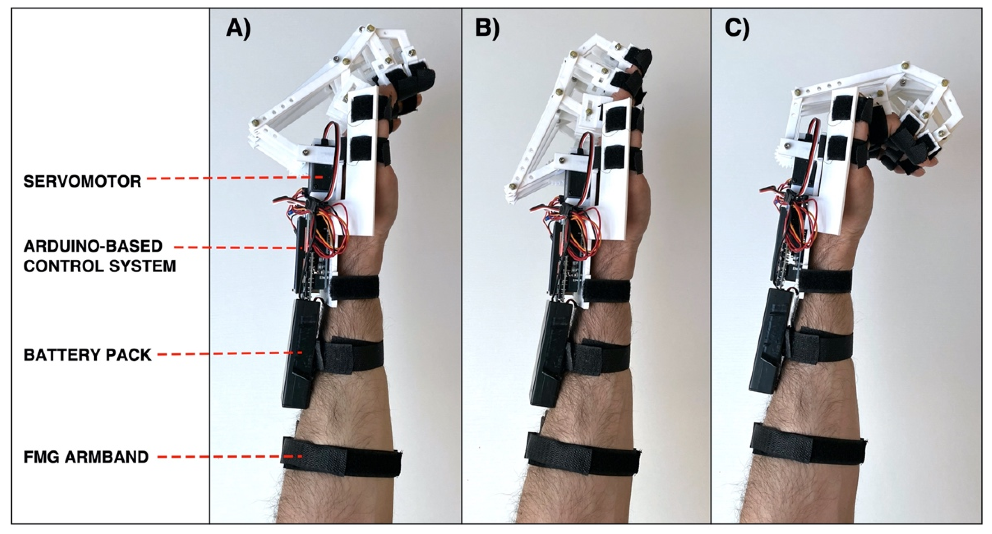
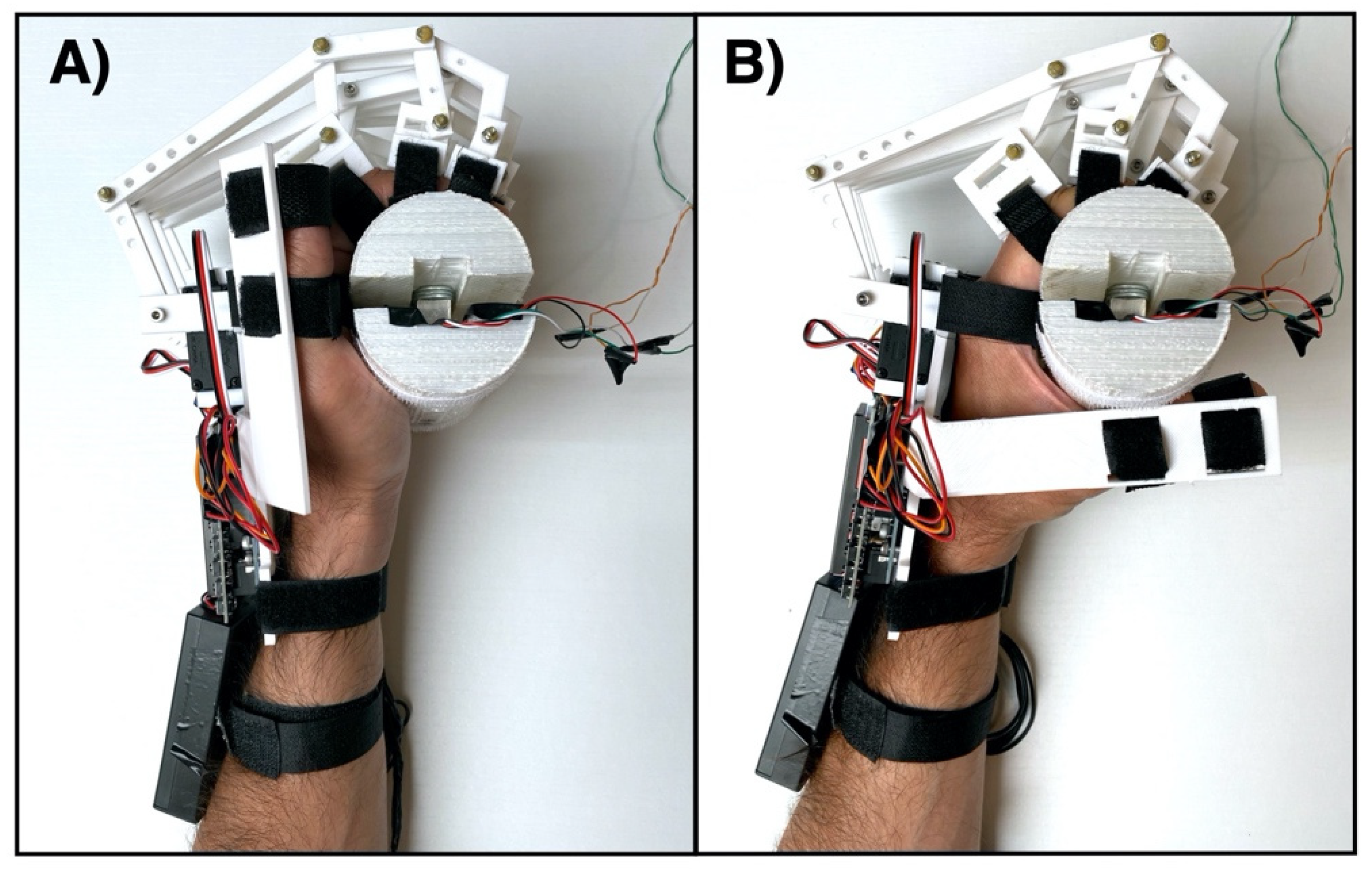
3.4. Current Realization of the Hand Exoskeleton

The design specifications for the hand exoskeleton are outlined in Table 1. The size was specified to be suitable for an adult man and the weight of the device was 380 g (500 g including the battery pack).

4. Discussion and Conclusions

This study presents a novel hand exoskeleton, which could help the user in activities of daily living (ADL) and be used in neurorehabilitation activities to recover the motor functions of the impaired hand. The device allows the user to perform both medium wrap and power sphere grasp, reaching about 40% of the required grasps for ADL [53]. The exoskeleton is low cost, 3D printable, lightweight (only 380 g, excluding the battery pack), fully wearable, portable and suitable for home use. Moreover, due to its modular design, the device can be easily customized for different users (left or right hand, different sizes, etc.). A single actuator (servomotor with torque of 25 kg/cm) moves the four fingers by means of a rigid transmission system coupled to the back of the hand, in order to keep the palm free. The underactuated mechanical system (one actuator for 11 DOF) allowed us to simplify the design, realization and assembly of the device. The thumb cannot be actively moved but only fixed in adduction or abduction positions through rigid supports, depending on the convenience for the specific task. As expected, the opposability of the thumb is much more convenient for grasping (see the tests with the handlebar). The mean power grasp with the thumb in the adduction position reached only 42% (40.13 N) of the force recorded with the thumb in the abduction position (94.61 N).
The simulation environment allowed us to size the actuator torque, in order to guarantee the capability to extend a hypertonic paretic hand in a clenched fist condition. The modeling of the kinematics of the exoskeleton was very reliable: the simulated trajectories of the phalanges were quite similar to the real ones (the correlation coefficients were about 0.9 or above). The exoskeleton kinematics were also similar to those of the natural hand. Indeed, the average cross-correlation coefficients computed between the trajectories described by the phalanges (of the natural and exoskeleton finger) while performing finger flexion movements were equal to 0.71, 0.81, 0.85 for proximal, medial and distal phalanges, respectively. Furthermore, when wearing the exoskeleton, the angular excursion of MCP, PIP and DIP joints was 52°, 80°, 10°, respectively. However, reductions of 37% (MCP), 1% (PIP) and 78% (DIP) were measured when compared to the excursions of the natural finger.
Regarding the exoskeleton control system, it is worth pointing out that force-myography (FMG) represents a valid alternative to surface electromyography (sEMG) for monitoring muscle contraction and piloting human–machine interfaces [19,47]. FMG provides a ready to use signal (no need for signal processing) that allows fast activation times of the exoskeleton: just 0.9 s from the muscle trigger to complete closing or opening of the hand. The system is designed to monitor the activation of two antagonist forearm muscles of the impaired arm via the FMG armband: the flexor carpi ulnaris and the extensor digitorum, which are monitored to interpret the user’s intents to flex or extend the fingers or remain in a resting condition. The user can voluntarily activate the flexion and extension of the exoskeleton fingers by starting the intentional movement and receiving the assistance of the device to complete the task. Alternatively, a different control approach based on the symmetrical master–slave motion strategy is suggested when the impaired arm (attempting muscle contraction) does not provide enough muscle swelling to activate the force sensors. In this case, the FMG armband needs to be worn on the healthy arm which provides a control signal to the exoskeleton mounted on the paretic contralateral hand. Different studies showed that bilateral movement training improves the motor functions of the hemiplegic arm, indeed, by exploiting the concept of “motor irradiation”, the muscle contraction of the heathy arm may increase the excitability of the homologous motor pathways in the impaired arm [41].
In future, it would be interesting to investigate the use of the proposed exoskeleton in exergaming rehabilitation applications. As showed in a review study by Rosly et al. [54], exergames for subjects with neuromotor impairments can provide outcomes with equivalent dose-potency as traditional physical exercise in clinic or home environments. Our previous study [30] already investigated the use of the aforementioned FMG armband for exergaming applications. Now, the synergy between the armband and the exoskeleton could be exploited to train subjects with a paretic hand to strengthen the voluntary control of the extensor and flexor muscles of the fingers, with the support of the exoskeleton which helps to execute the movements in a virtual environment. Indeed, simple graphical interfaces, such as the one inspired by Pong [55], can be used to this purpose; as an example, the player can control a bar by moving it horizontally to the left or right side of the screen by performing extension or flexion movements of the fingers (using the left hand), respectively, and trying to intercept a ball coming from the top of the graphical interface from randomized directions. Figure 13 shows how the hand exoskeleton can be implemented in exergaming applications.
However, some current limitations should be addressed in future studies. The thumb support can be only fixed in the adduction or abduction position. Future improvements of the exoskeleton could be the development of a mechanical system able to move the four fingers and thumb together, as in the natural hand. Most likely, more actuators would be needed, increasing the complexity of the mechanics and the controller.
In addition, the current uniform distribution of the actuator torque among the four exoskeleton fingers may evolve into a differential distribution [26], to better exploit the redundancy of the fingers in grasping objects of different shapes and textures and provide a more effective adaptive grip.
To date, we have considered literature data regarding the grip force of a typical post-stroke patient’s hand. Obviously, the stiffness of the finger joints may vary over the course of the disease. As an example, the typical initial spasticity, if left untreated, can worsen in much stiffer contractures.
Ultimately, initial tests were conducted only on few healthy subjects and further tests involving post-stroke patients with varying levels of motor impairment are needed, to better evaluate and improve the performance of the device in real scenarios.

Supplementary Materials

The information to reproduce the hand exoskeleton (including CAD files and other documentation) can be downloaded from: https://0-www-doi-org.brum.beds.ac.uk/10.6084/m9.figshare.16635316 (accessed on 5 December 2021).

Author Contributions

Conceptualization, D.E., P.B.; design and control of the exoskeleton prototype, methodology, formal analysis, D.E.; investigation, D.E., J.C., E.A., S.S., G.D.G., G.R.N., P.B.; writing—original draft preparation and visualization, D.E.; writing—review and editing, D.E., J.C., E.A., S.S., G.D.G., G.R.N., P.B.; supervision, P.B. All authors have read and agreed to the published version of the manuscript.

Funding

This research received no external funding.

Institutional Review Board Statement

Not applicable.

Informed Consent Statement

The tests performed were carried out only by the authors of the manuscript, who are healthy people and have signed an informed consent.

Data Availability Statement

Not applicable.

Conflicts of Interest

The authors declare no conflict of interest.

References

  1. Tjahyono, A.P.; Aw, K.C.; Devaraj, H.; Surendra, W.; Haemmerle, E.; Travas-Sejdic, J. A Five-fingered Hand Exoskeleton Driven by Pneumatic Artificial Muscles with Novel Polypyrrole Sensors. Ind. Robot. Int. J. 2013, 40, 251–260. [Google Scholar] [CrossRef]
  2. Bi, Q.; Yang, C. Human-Machine Interaction Force Control: Using a Model-Referenced Adaptive Impedance Device to Control an Index Finger Exoskeleton. J. Zhejiang Univ. Sci. C 2014, 15, 275–283. [Google Scholar] [CrossRef]
  3. Burton, T.M.W.; Vaidyanathan, R.; Burgess, S.C.; Turton, A.J.; Melhuish, C. Development of a Parametric Kinematic Model of the Human Hand and a Novel Robotic Exoskeleton. In Proceedings of the 2011 IEEE International Conference on Rehabilitation Robotics, Zurich, Switzerland, 29 June–1 July 2011; pp. 1–7. [Google Scholar]
  4. Kuswanto, D.; Iskandriawan, B.; Mahardhika, P.S. Power Grip Exoskeleton Design as Rehabilitation Devices for Post-Stroke Survivors. In Proceedings of the 2018 1st International Conference on Bioinformatics, Biotechnology, and Biomedical Engineering—Bioinformatics and Biomedical Engineering, Yogyakarta, Indonesia, 19–20 October 2018. [Google Scholar] [CrossRef]
  5. Hatem, S.M.; Saussez, G.; della Faille, M.; Prist, V.; Zhang, X.; Dispa, D.; Bleyenheuft, Y. Rehabilitation of Motor Function after Stroke: A Multiple Systematic Review Focused on Techniques to Stimulate Upper Extremity Recovery. Front. Hum. Neurosci. 2016, 10, 442. [Google Scholar] [CrossRef] [PubMed] [Green Version]
  6. Mawase, F.; Cherry-Allen, K.; Xu, J.; Anaya, M.; Uehara, S.; Celnik, P. Pushing the Rehabilitation Boundaries: Hand Motor Impairment Can Be Reduced in Chronic Stroke. Neurorehabil. Neural. Repair. 2020, 34, 733–745. [Google Scholar] [CrossRef] [PubMed]
  7. Cordo, P.; Wolf, S.; Lou, J.-S.; Bogey, R.; Stevenson, M.; Hayes, J.; Roth, E. Treatment of Severe Hand Impairment Following Stroke by Combining Assisted Movement, Muscle Vibration, and Biofeedback. J. Neurol. Phys. Ther. 2013, 37, 194–203. [Google Scholar] [CrossRef] [PubMed]
  8. Kamper, D.G.; Fischer, H.C.; Cruz, E.G.; Rymer, W.Z. Weakness Is the Primary Contributor to Finger Impairment in Chronic Stroke. Arch. Phys. Med. Rehabil. 2006, 87, 1262–1269. [Google Scholar] [CrossRef] [PubMed]
  9. Ates, S.; Haarman, C.J.W.; Stienen, A.H.A. SCRIPT Passive Orthosis: Design of Interactive Hand and Wrist Exoskeleton for Rehabilitation at Home after Stroke. Auton. Robot 2017, 41, 711–723. [Google Scholar] [CrossRef] [Green Version]
  10. James, C.; Kathye, L.; Sangbum, K.; Mary, T.; Andrea, B. Chronic Motor Dysfunction After Stroke. Stroke 2000, 31, 1360–1364. [Google Scholar] [CrossRef]
  11. Schabowsky, C.N.; Godfrey, S.B.; Holley, R.J.; Lum, P.S. Development and Pilot Testing of HEXORR: Hand EXOskeleton Rehabilitation Robot. J. NeuroEngineering Rehabil. 2010, 7, 36. [Google Scholar] [CrossRef] [Green Version]
  12. McConnell, A.; Kong, X.; Vargas, P.A. A Novel Robotic Assistive Device for Stroke-Rehabilitation. In Proceedings of the 23rd IEEE International Symposium on Robot and Human Interactive Communication, Edinburgh, UK, 25–29 August 2014; pp. 917–923. [Google Scholar]
  13. Lee, S.W.; Landers, K.A.; Park, H.-S. Development of a Biomimetic Hand Exotendon Device (BiomHED) for Restoration of Functional Hand Movement Post-Stroke. IEEE Trans. Neural. Syst. Rehabil. Eng. 2014, 22, 886–898. [Google Scholar] [CrossRef] [Green Version]
  14. Lindberg, P.G.; Roche, N.; Robertson, J.; Roby-Brami, A.; Bussel, B.; Maier, M.A. Affected and Unaffected Quantitative Aspects of Grip Force Control in Hemiparetic Patients after Stroke. Brain Res. 2012, 1452, 96–107. [Google Scholar] [CrossRef] [PubMed]
  15. Aqueveque, P.; Ortega, P.; Pino, E.; Saavedra, F.; Germany, E.; Gómez, B. After Stroke Movement Impairments: A Review of Current Technologies for Rehabilitation. In Disabilities—Therapeutic Implications; Under, T., Ed.; InTechOpen: London, UK, 2017; pp. 95–116. [Google Scholar] [CrossRef] [Green Version]
  16. Rahman, M.A.; Al-Jumaily, A. Design and Development of a Hand Exoskeleton for Rehabilitation Following Stroke. Procedia Eng. 2012, 41, 1028–1034. [Google Scholar] [CrossRef] [Green Version]
  17. Dobkin, B.H. Strategies for Stroke Rehabilitation. Lancet Neurol. 2004, 3, 528–536. [Google Scholar] [CrossRef] [Green Version]
  18. Langhorne, P.; Bernhardt, J.; Kwakkel, G. Stroke Rehabilitation. Lancet 2011, 377, 1693–1702. [Google Scholar] [CrossRef]
  19. Esposito, D.; Centracchio, J.; Andreozzi, E.; Gargiulo, G.D.; Naik, G.R.; Bifulco, P. Biosignal-Based Human–Machine Interfaces for Assistance and Rehabilitation: A Survey. Sensors 2021, 21, 6863. [Google Scholar] [CrossRef]
  20. du Plessis, T.; Djouani, K.; Oosthuizen, C. A Review of Active Hand Exoskeletons for Rehabilitation and Assistance. Robotics 2021, 10, 40. [Google Scholar] [CrossRef]
  21. Basmajian, J.V.; Luca, C.J. Muscles Alive: Their Functions Revealed by Electromyography. J. Med. Educ. 1962, 37, 802. [Google Scholar]
  22. Konrad, P. The ABC of EMG: A Practical Introduction to Kinesiological Electromyography, 1st ed.; Noraxon: Scottsdale, AZ, USA, 2005. [Google Scholar]
  23. Gargiulo, G.; Bifulco, P.; McEwan, A.; Nasehi Tehrani, J.; Calvo, R.A.; Romano, M.; Ruffo, M.; Shephard, R.; Cesarelli, M.; Jin, C.; et al. Dry Electrode Bio-Potential Recordings. Annu. Int. Conf. IEEE. Eng. Med. Biol. Soc. 2010, 2010, 6493–6496. [Google Scholar] [CrossRef] [Green Version]
  24. Esposito, D.; Andreozzi, E.; Fratini, A.; Gargiulo, G.D.; Savino, S.; Niola, V.; Bifulco, P. A Piezoresistive Sensor to Measure Muscle Contraction and Mechanomyography. Sensors 2018, 18, 2553. [Google Scholar] [CrossRef] [Green Version]
  25. Esposito, D.; Gargiulo, G.D.; Parajuli, N.; Cesarelli, G.; Andreozzi, E.; Bifulco, P. Measurement of Muscle Contraction Timing for Prosthesis Control: A Comparison between Electromyography and Force-Myography. In Proceedings of the 2020 IEEE International Symposium on Medical Measurements and Applications (MeMeA), Bari, Italy, 1 June–1 July 2020; pp. 1–6. [Google Scholar]
  26. Esposito, D.; Savino, S.; Andreozzi, E.; Cosenza, C.; Niola, V.; Bifulco, P. The “Federica” Hand. Bioengineering 2021, 8, 128. [Google Scholar] [CrossRef]
  27. Esposito, D.; Cosenza, C.; Gargiulo, G.D.; Andreozzi, E.; Niola, V.; Fratini, A.; D’Addio, G.; Bifulco, P. Experimental Study to Improve “Federica” Prosthetic Hand and Its Control System. In Proceedings of the XV Mediterranean Conference on Medical and Biological Engineering and Computing—MEDICON 2019, Coimbra, Portugal, 26–28 September 2019; pp. 586–593. [Google Scholar]
  28. Esposito, D.; Savino, S.; Cosenza, C.; Gargiulo, G.D.; Fratini, A.; Cesarelli, G.; Bifulco, P. Study on the Activation Speed and the Energy Consumption of “Federica” Prosthetic Hand. In Proceedings of the XV Mediterranean Conference on Medical and Biological Engineering and Computing—MEDICON 2019, Coimbra, Portugal, 26–28 September 2019; pp. 594–603. [Google Scholar]
  29. Esposito, D.; Savino, S.; Cosenza, C.; Andreozzi, E.; Gargiulo, G.D.; Polley, C.; Cesarelli, G.; D’Addio, G.; Bifulco, P. Evaluation of Grip Force and Energy Efficiency of the “Federica” Hand. Machines 2021, 9, 25. [Google Scholar] [CrossRef]
  30. Esposito, D.; Andreozzi, E.; Gargiulo, G.D.; Fratini, A.; D’Addio, G.; Naik, G.R.; Bifulco, P. A Piezoresistive Array Armband With Reduced Number of Sensors for Hand Gesture Recognition. Front. Neurorobot. 2020, 13. [Google Scholar] [CrossRef] [PubMed] [Green Version]
  31. Esposito, D.; Gargiulo, G.D.; Polley, C.; D’Addio, G.; Bifulco, P. Improvements of a Simple Piezoresistive Array Armband for Gesture Recognition. In Proceedings of the 2020 International Conference on e-Health and Bioengineering (EHB), Iasi, Romania, 29–30 October 2020; pp. 1–5. [Google Scholar]
  32. Andreozzi, E.; Centracchio, J.; Punzo, V.; Esposito, D.; Polley, C.; Gargiulo, G.D.; Bifulco, P. Respiration Monitoring via Forcecardiography Sensors. Sensors 2021, 21, 3996. [Google Scholar] [CrossRef] [PubMed]
  33. Andreozzi, E.; Fratini, A.; Esposito, D.; Naik, G.; Polley, C.; Gargiulo, G.D.; Bifulco, P. Forcecardiography: A Novel Technique to Measure Heart Mechanical Vibrations onto the Chest Wall. Sensors 2020, 20, 3885. [Google Scholar] [CrossRef] [PubMed]
  34. Andreozzi, E.; Gargiulo, G.D.; Esposito, D.; Bifulco, P. A Novel Broadband Forcecardiography Sensor for Simultaneous Monitoring of Respiration, Infrasonic Cardiac Vibrations and Heart Sounds. Front. Physiol. 2021, 12, 1988. [Google Scholar] [CrossRef] [PubMed]
  35. Islam, M.R.U.; Waris, A.; Kamavuako, E.N.; Bai, S. A Comparative Study of Motion Detection with FMG and SEMG Methods for Assistive Applications. J. Rehabil. Assist. Technol. Eng. 2020, 7, 2055668320938588. [Google Scholar] [CrossRef] [PubMed]
  36. Randazzo, L.; Iturrate, I.; Perdikis, S.; Millán, J.d.R. Mano: A Wearable Hand Exoskeleton for Activities of Daily Living and Neurorehabilitation. IEEE Robot Autom. Lett. 2018, 3, 500–507. [Google Scholar] [CrossRef] [Green Version]
  37. Araujo, R.S.; Silva, C.R.; Netto, S.P.N.; Morya, E.; Brasil, F.L. Development of a Low-Cost EEG-Controlled Hand Exoskeleton 3D Printed on Textiles. Front. Neurosci. 2021, 15, 661569. [Google Scholar] [CrossRef]
  38. Wege, A.; Zimmermann, A. Electromyography Sensor Based Control for a Hand Exoskeleton. In Proceedings of the 2007 IEEE International Conference on Robotics and Biomimetics (ROBIO), Sanya, China, 15–18 December 2007. [Google Scholar] [CrossRef]
  39. Ho, N.S.K.; Tong, K.Y.; Hu, X.L.; Fung, K.L.; Wei, X.J.; Rong, W.; Susanto, E.A. An EMG-Driven Exoskeleton Hand Robotic Training Device on Chronic Stroke Subjects: Task Training System for Stroke Rehabilitation. In Proceedings of the 2011 IEEE International Conference on Rehabilitation Robotics, Zurich, Switzerland, 29 June–1 July 2011; pp. 1–5. [Google Scholar]
  40. Dwivedi, A.; Gerez, L.; Hasan, W.; Yang, C.-H.; Liarokapis, M. A Soft Exoglove Equipped With a Wearable Muscle-Machine Interface Based on Forcemyography and Electromyography. IEEE Robot. Autom. Lett. 2019, 4, 3240–3246. [Google Scholar] [CrossRef]
  41. Carson, R.G. Neural Pathways Mediating Bilateral Interactions between the Upper Limbs. Brain Res. Rev. 2005, 49, 641–662. [Google Scholar] [CrossRef]
  42. Summers, J.J.; Kagerer, F.A.; Garry, M.I.; Hiraga, C.Y.; Loftus, A.; Cauraugh, J.H. Bilateral and Unilateral Movement Training on Upper Limb Function in Chronic Stroke Patients: A TMS Study. J. Neurol. Sci. 2007, 252, 76–82. [Google Scholar] [CrossRef]
  43. Loconsole, C.; Leonardis, D.; Barsotti, M.; Solazzi, M.; Frisoli, A.; Bergamasco, M.; Troncossi, M.; Foumashi, M.M.; Mazzotti, C.; Castelli, V.P. An Emg-Based Robotic Hand Exoskeleton for Bilateral Training of Grasp. In Proceedings of the 2013 World Haptics Conference (WHC), Daejeon, Korea, 14–17 April 2013; pp. 537–542. [Google Scholar]
  44. Ueki, S.; Kawasaki, H.; Ito, S.; Nishimoto, Y.; Abe, M.; Aoki, T.; Ishigure, Y.; Ojika, T.; Mouri, T. Development of a Hand-Assist Robot With Multi-Degrees-of-Freedom for Rehabilitation Therapy. IEEE/ASME Trans. Mechatron. 2012, 17, 136–146. [Google Scholar] [CrossRef]
  45. Cortese, M.; Cempini, M.; de Almeida Ribeiro, P.R.; Soekadar, S.R.; Carrozza, M.C.; Vitiello, N. A Mechatronic System for Robot-Mediated Hand Telerehabilitation. IEEE/ASME Trans. Mechatron. 2015, 20, 1753–1764. [Google Scholar] [CrossRef]
  46. Liu, Y.; Yu, H. A Survey of Underactuated Mechanical Systems. IET Control. Theory Appl. 2013, 7, 921–935. [Google Scholar] [CrossRef] [Green Version]
  47. Xiao, Z.G.; Menon, C. A Review of Force Myography Research and Development. Sensors 2019, 19, 4557. [Google Scholar] [CrossRef] [Green Version]
  48. Fusion 360|3D CAD, CAM, CAE & PCB Cloud-Based Software|Autodesk. Available online: https://www.autodesk.com/products/fusion-360/overview (accessed on 22 June 2021).
  49. Arduino Uno Rev3|Arduino Official Store. Available online: https://store.arduino.cc/arduino-uno-rev3 (accessed on 18 November 2020).
  50. Simscape Multibody. Available online: https://it.mathworks.com/products/simscape-multibody.html (accessed on 22 June 2021).
  51. Boissy, P.; Bourbonnais, D.; Carlotti, M.M.; Gravel, D.; Arsenault, B.A. Maximal Grip Force in Chronic Stroke Subjects and Its Relationship to Global Upper Extremity Function. Clin. Rehabil. 1999, 13, 354–362. [Google Scholar] [CrossRef] [PubMed]
  52. Kinovea. Available online: https://www.kinovea.org/ (accessed on 4 September 2021).
  53. Dollar, A.M. Classifying Human Hand Use and the Activities of Daily Living. In The Human Hand as an Inspiration for Robot Hand Development; Balasubramanian, R., Santos, V.J., Eds.; Springer International Publishing: Cham, Switzerland, 2014; pp. 201–216. ISBN 978-3-319-03017-3. [Google Scholar]
  54. Mat Rosly, M.; Mat Rosly, H.; Davis Oam, G.M.; Husain, R.; Hasnan, N. Exergaming for Individuals with Neurological Disability: A Systematic Review. Disabil. Rehabil. 2017, 39, 727–735. [Google Scholar] [CrossRef]
  55. Pong. Wikipedia 2021. Available online: https://en.wikipedia.org/wiki/Pong (accessed on 8 September 2021).
Figure 1. The 3D renderings of the hand exoskeleton: (A) view from the thumb side; (B) view from the little finger side.
Machines 10 00057 g001
Figure 2. The 3D renderings of the components of the exoskeleton: (A) focus on the mechanical transmission system from the servomotor to the finger actuator arms; (B) side view of the rigid transmission system coupled to a finger, showing the supports (and the constraints) realized for each phalanx.
Machines 10 00057 g002
Figure 3. Circuit diagram of the control system based on an Arduino board (RG1-2 = 10 KΩ; C = 0.47 mF).
Machines 10 00057 g003
Figure 4. (A) Picture of the hand exoskeleton (top view): the actuator (25 kg cm servomotor), the Arduino UNO board with the superimposed LCD shield, the FMG armband based on 2 FSR-based sensors, the conditioning circuit for the FSR-based sensors and the battery pack (2 × 3.7 V, 3000 mAh) are highlighted; (B) FSR-based sensors positioned on the flexor carpi ulnaris and the extensor digitorum of the user’s forearm.
Machines 10 00057 g004
Figure 5. Side view in different exoskeleton positions: (A) at rest; (B) finger extension (open hand); (C) finger flexion (closed hand).
Machines 10 00057 g005
Figure 6. Example of symmetrical master–slave motion strategy: the user’s healthy hand on the master side (right hand) activates the motion for the paretic hand on the slave side (left hand).
Machines 10 00057 g006
Figure 7. An image captured during the simulation test. The proximal, medial and distal phalanges were modeled as cylinders connected together by MCP, PIP and DIP joints, respectively.
Machines 10 00057 g007
Figure 8. Finger force and actuator torque in the simulation environment: panels (A,B) show the finger force and the related actuator torque, from the extended position to the flexed position of the finger; panels (C,D) show the finger force and the related actuator torque, from the flexed position to the extended position.
Machines 10 00057 g008
Figure 9. Trajectories described by each phalanx of the index finger (depicted in different colors) of the natural hand during the flexion movement.
Machines 10 00057 g009
Figure 10. Trajectories described by each phalanx of the index finger (depicted in different colors) of the hand exoskeleton during flexion movement in a real scenario.
Machines 10 00057 g010
Figure 11. Trajectories described by each phalanx of the index finger (depicted in different colors) of the hand exoskeleton during flexion movement in the simulation environment (SimScape).
Machines 10 00057 g011
Figure 12. Power grasp test by means of the sensorized handlebar: (A) test with the thumb in the adduction position (i.e., aligned to the fingers); (B) test with the thumb in the abduction position (i.e., in opposition to the fingers).
Machines 10 00057 g012
Figure 13. Flowchart describing exergaming applications with the use of the hand exoskeleton.
Machines 10 00057 g013
Table 1. Design specifications for the hand exoskeleton.
ItemSpecification
sizesuitable for an adult man
weight380 g (500 g including the battery pack)
modularityYes
actuator1 servomotor (25 kg/cm)
degrees of freedom (DOF)11
hand closing time (from trigger to complete closure)≈0.9 s
hand opening time (from trigger to complete opening)≈0.9 s
power grasp force94.61 N (SD: 1.92 N)
energy power2 × 3.7 V batteries (3000 mAh)
Publisher’s Note: MDPI stays neutral with regard to jurisdictional claims in published maps and institutional affiliations.

