
Teaching Motion Control in Mechatronics Education Using an Open Framework Based on the Elevator Model

Department of Engineering Sciences, University of Agder (UiA), NO-4879 Grimstad, Norway
*
Author to whom correspondence should be addressed.
Machines 2022, 10(10), 945; https://0-doi-org.brum.beds.ac.uk/10.3390/machines10100945
Submission received: 9 September 2022
/
Revised: 26 September 2022
/
Accepted: 10 October 2022
/
Published: 18 October 2022
(This article belongs to the Special Issue Modeling, Sensor Fusion and Control Techniques in Applied Robotics)
Abstract
:Universities and other educational institutions may find it difficult to afford the cost of obtaining cutting-edge teaching resources. This study introduces the adoption of a novel open prototyping framework in the context of mechatronics education, employing low-cost commercial off-the-shelf (COTS) components and tools for the motion control module. The goal of this study is to propose a novel structure for the motion control module in the engineering mechatronics curriculum. The objective is to foster a new teaching method. From a methodology perspective, students are involved in a series of well-organised theoretical lectures as well as practical, very engaging group projects in the lab. To help students understand, draw connections, and broaden their knowledge, the methods of surface learning and deep learning are frequently mixed thoroughly. The structure of the course as well as the key topics are discussed. The proposed open framework, which consists of an elevator model, is presented in details. Students’ early evaluation indicates that the course organisation and subjects are successful and beneficial.
1. Introduction
Motion control is a branch of automation that includes the systems and components involved in the controlled movement of machine parts. Motion control systems are widely utilised for automation in a variety of industries, including precision engineering, micromanufacturing, biotechnology, and nanotechnology [1]. One or more prime movers or actuators, as well as an energy amplifier, are frequently used in motion control systems. Motion control may be divided into two categories: open loop and closed loop. In systems with an open loop, the controller sends a command to the actuator via the amplifier without being able to verify that the desired motion was really achieved. Such a common setup might control a fan or a stepper motor. For better control and accuracy, the system could be upgraded with a measuring tool or sensor (usually near the end motion). In the latter scenario, the system turns into a closed loop since the measurement is converted into a signal and sent back to the controller, which then corrects for any inaccuracies. Typically, some form of device, such as a hydraulic pump, linear actuator, or electric motor, often referred to as a servo, is used to regulate the position or velocity of moving machinery. Motion control is primarily concerned with automating the control of motion systems that use electric actuators, such as DC/AC servo motors. Since most robotic manipulators are powered by electrical servo motors and their main function is motion control, controlling robotic manipulators is also seen as being under the umbrella of motion control [2].
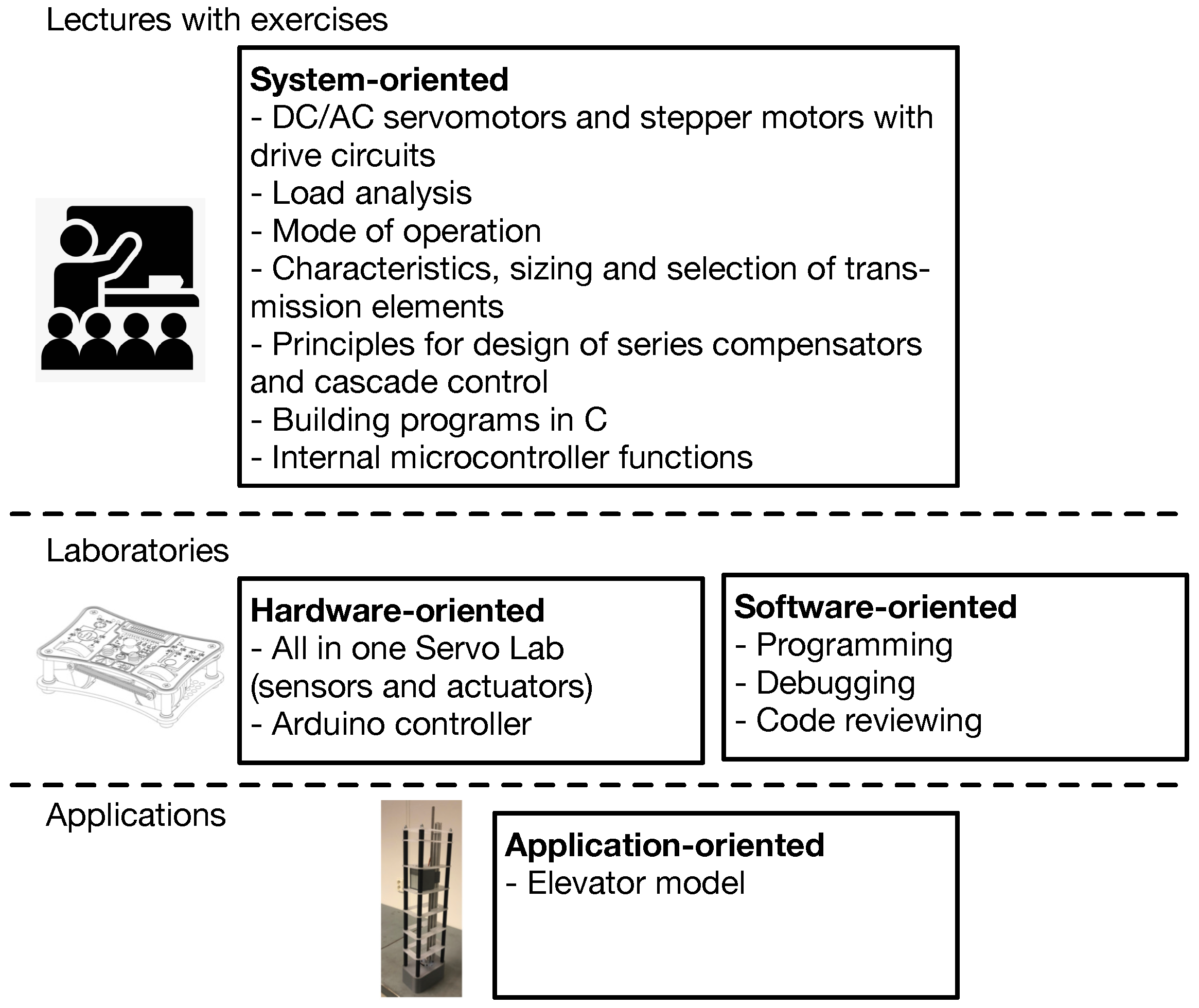
In this work, a novel organisation of the motion control module for the engineering mechatronics education curriculum is presented. The aim is to inspire a new approach to teaching the course. Inspired by our previous work [3,4,5], this study intends to address the following research question: can thoroughly alternating surface and deep learning sessions increase understanding, activate relationships, and enhance students’ knowledge? The basic idea is to organise the course into three parallel levels, as indicated in Figure 1:
- Lectures that combine theory and exercises. This component of the module is systems oriented and focuses on system requirements, modelling, methods for analysis and design of motion control systems, and control. Exercises are given and done in scheduled hours with close supervision;
- Laboratory. This component of the course is designed to be both hardware-oriented, by focusing on selecting the necessary sensors and actuators, as well as software-oriented, by focusing on programming, debugging and reviewing. The laboratory is based on a group project;
- Applications. Both the theoretical lectures and the laboratory work are aimed at providing students with an improved hands-on experience with rapid-prototyping of motion control systems.
The presented course is MAS246-G [6]. This course is a 5th semester module of the three-year bachelor’s degree programme in Mechatronics given at the Department of Engineering Sciences, Faculty of Engineering and Science, University of Agder (UiA), Grimstad, Norway. Recommended previous knowledge for the course includes MAS239 Feedback Control Systems 1 [7], MAS134 Electrical circuits and digital engineering [8], MA178 Mathematics 1 [9], MA-179 Mathematics 2 [10], or equivalent. This article outlines the overall structure of the course as well as the primary themes.
The paper is organised as follows: Section 2 provides an overview of the chosen educational tools. Section 3 depicts the course overview, while the laboratories are presented in Section 4. Section 5 describes the selected elevator model. The proposed architecture for the elevator model is presented in Section 6. Section 7, the course learning outcomes and the students’ feedback are defined and analysed. Finally, Section 8 contains the conclusions and recommendations for further studies.
2. Pedagogical Tools
The presented course (MAS246-G [6]) is designed by considering coordinated teaching across the whole Bachelor’s Programme in Mechatronics [11].
The proposed course is built on the foundation of the unified modelling language (UML) [12]. This decision is based on the fact that UML has the potential to be used to create a strong educational and scientific foundation with mechatronic systems design as the cornerstone, ensuring a methodical and even-handed integration of principles from mechanical engineering, electric/electronic engineering, control engineering, and computer engineering [13].
The Arduino [14] platform is adopted as a developing tool. This choice is motivated by a variety of reasons. Arduino is a free and open-source electronics prototyping platform with a variety of hardware and software capabilities. The amount of hardware and software development required to obtain a system up and running is minimised when using Arduino boards [15]. On the software side, Arduino offers a wide range of libraries that make programming the microcontroller simple. The use of Arduino boards simplifies the system framework’s maintenance and allows for the addition of new features in the future.
3. Course Overview
The proposed course structure and primary themes are described in this section. The course material includes theoretical lectures, laboratory classes, and one course project, as depicted in Table 1. Each 6-hour theoretical lecture is held once a week and followed by a weekly 6-hour laboratory session. The topics covered in each lecture are listed below.
3.1. Lecture 1: Introduction on Direct Current (DC) Machines
In this lecture, a description of the direct current (DC) machines working principles, construction and commutation forms is presented and then the development of a mathematical model of a DC motor as an electromechanical system with differential equations and block diagrams for first-order and second-order control systems. A first order control system is defined as a type of control system whose input–output relationship (also known as a transfer function) is a first-order differential equation. A second-order control system is a system whose transfer function is a second-order differential equation.
3.2. Lecture 2: DC Machine’s Various Drive Circuits and Operations
A review of the DC machine’s various drive circuits is introduced, such as linear and pulse–width modulation (PWM), with an H-bridge for current velocity and position control. Moreover, the four-quadrant operation mode is studied. A servo system capable of controlling velocity and torque in both positive and negative directions is known as having four-quadrant operation [16].
3.3. Lecture 3: Modelling of a DC Motor as a Thermal System
In this lecture, we consider the modelling of a DC motor as a thermal system and the selection of speed profiles. Successively, load analysis with inertia friction and damping reflected to the motor shaft is used as a basis for sizing and selection of DC motors to specific applications.
3.4. Lecture 4: Stepper Motor Types and Working Principles
In this lecture, we present different stepper motor types, working principles, construction and behaviour with different commutation forms, such as half, full and micro stepping [17].
3.5. Lecture 5: Control Methods for Stepper Motors
Control methods for stepper motors are presented. Moreover, stepper motor drive circus for unipolar and bipolar operation with L/R drives and chopper drives are also introduced [18]. Open loop control of speed and position is outlined. Methods for sizing and selection of step motors for applications based on torque/velocity curves are considered.
3.6. Lecture 6: Brushless DC Electric Motors
In this lecture, brushless DC electric motors (BLDC motors or BL motors) are introduced. A BLDC motor, also known as an electronically commutated motor (ECM or EC motor) or synchronous DC motor, is a synchronous motor using a direct current (DC) electric power supply. BLDC working principles are presented including construction and commutation forms. Successively, the three-phase induction motors are presented. These motors are based on the principle of electromagnetic induction. A three-phase stator’s construction and operation are discussed including control of rotor field orientation and measurement of the orientation of the rotor field. Finally, six-step commutation of BLDC motors using sensor feedback is presented [19,20].
3.7. Lecture 7: Permanent-Magnet Synchronous Motors (PMSM)
Operating principles of permanent-magnet synchronous motors (PMSM) are introduced [21]. Measurements of the rotor position (i.e., syncro, encoders) are discussed. We also introduce a commutation system based on Field-Oriented Control (FOC) [22], and a d-q reference frame with Park and Clarke variable transformation [23].
3.8. Lecture 8: Rotary to Rotary Motion Transmissions
An introduction of rotary to rotary motion transmissions is given. Different aspects are discussed including gear determination, stiffness, efficiency, turnover, ratio, momentum and speed. Gears as a transmission components are outlined. A review is then provided about important characteristics of matching between engine and load, as well as specific characteristics and requirements related to the operation of servo systems. Successively, we consider sizing and selection of gears with regard to inertia matching between engine and load. Then, a study regarding selection of gear ratio based on torque and angular velocity matching is considered. Advantages and disadvantages of different gear types are discussed.
3.9. Lecture 9: Rotary to Translational Motion Transmissions
An introduction to rotary to translational motion transmission mechanisms is provided. Successively, we introduce lead–screw, ball–screw mechanisms, and rack and pinion mechanisms. Finally, sizing and selection of tangential and screw mechanisms are considered.
3.10. Lecture 10: Shaft Selection and Sizing
Methods for selecting and sizing the correct shaft dimension are considered. Successively, we consider the challenge of shaft coupling for motion control applications.
3.11. Lecture 11: Lead–Lag Compensators
We consider the frequency response design for lead–lag compensators [24]. Successively, we consider the design procedure to to fulfil performance specifications stability–overshoot–set point tracking.
3.12. Lecture 12: Modern Motion Control Architecture
We introduce modern motion control architectures. A procedure to design multi-loop motion control systems is discussed. The integration of cascade plus feed-forward control can bring the system to obtain better results in terms of trajectory tracking and disturbance rejection.
4. Laboratories Overview
The laboratory sessions run in parallel with the theoretical lectures introduced in Section 3. The key laboratory subjects are outlined in the following section.
4.1. Programming in Practice: Arduino
The goal of this lab is to introduce the use of Arduino [14] as a developing platform for motion control. Arduino is a well-known tool for generating applications and deploying educational content [25]. Motion control necessitates a number of skills and abilities that can be easily developed using tools such as Arduino. Arduino can be used to create interactive objects that accept input from various switches or sensors and operate lights, actuators, and other physical outputs. Arduino projects can be self-contained or interfaced with software running on a computer. The boards can be hand-assembled or purchased pre-assembled, with the open-source IDE available for free download. The following topics are introduced: functions, variables, structures (i.e., setup, loop, if, else, while, for, do while), analog and digital signals, and PWM. Particular emphasis is then placed on the practical implementation and tuning of a proportional integral derivative (PID) controller [26].
4.2. Unified Modelling Language (UML) and Class Exercise
An introduction of various paradigms and models for the development of embedded systems is provided, with a focus on design strategies such as incremental and waterfall approaches [27]. Successively, an introduction of UML is given with particular emphasis on embedded systems. Different diagrams are introduced including use case diagrams, class diagrams, sequence diagrams and state machine diagrams [12]. These diagrams are meant to support the design and development of the course project.
4.3. All in One Servo Lab (AIOSL)
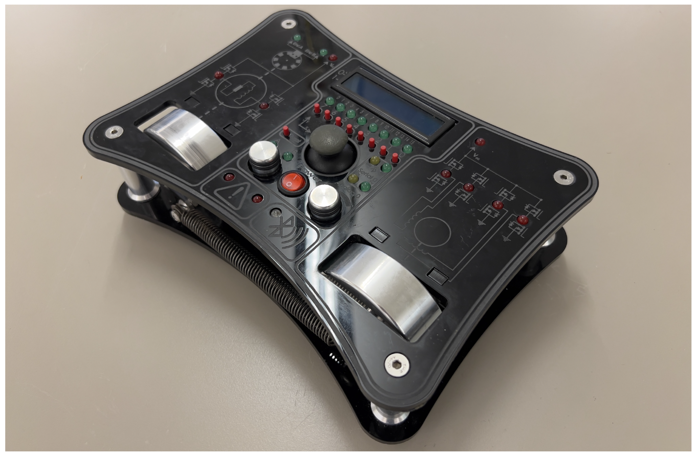
Servo technology and servo-control are important components of motion control, and working with servo systems necessitates the application of mechanics, mathematics, electronics, and control systems’ engineering methods. Furthermore, the subject requires microcontroller programming. To facilitate the learning process for students, a novel platform is designed for doing practical laboratory assignments, simulations and demonstrations. The development of this platform is based on the following key requirements: (i) ease of use, plug and play (PnP), and (ii) student engagement, so that working with the platform should be fun. To meet these requirements, we have developed a single unit platform with servo and stepper motors, various inputs and feedback options. Moreover, feedback front-end-software is provided, while laboratory assignments with solutions and manuals are in development. This platform is named “all in one servo lab” (AIOSL) [28], and it is shown in Figure 2.
Among other components, the AIOSL embeds two motors: a brushed DC motor and a two-phase stepper motor, respectively. This allows students to develop multi-function applications. The DC motor gives students the possibility to design software for motor control and to utilise lead–lag regulation. For closed loop control, feedback from the embedded encoder is necessary. This application challenges the students’ ability to regulate micro-stepping. The components of the AIOSL are integrated in the chassis, while also providing a functional design. In fact, the motors are exposed through the top panel, giving a more visual perception of their status and allowing the students to affect their flywheels. The AIOSL is equipped with a HC-05 Bluetooth serial module. This module allows the Arduino controller to send serial strings over Bluetooth to another device that supports Bluetooth serial data. The module can act both as a slave and a master.
In contrast to off-the-shelf devices, the customisation of the AIOSL enables the lecturer to create specialised tasks for the students. In addition, it eliminates time-waste related to setup, which may take away focus from the assignment itself.
From a hardware perspective, an Arduino Mega [14] is integrated into the AIOSL. The Arduino platform is an extremely versatile platform, and is supported through several programming languages. The AIOSL is designed to be programmed mainly with C and C++ languages, preferably with the Arduino integrated development environment (IDE).
Additional existing or custom-made libraries may be included. The libraries are written in C++ and allow for the inclusion of objective-based programming, which enhances the programming level from a logic perspective.
5. Elevator Model
The course project aims at designing a complete elevator system to be implemented based on the AIOSL. This may be achieved by exclusively using the integrated actuators and sensors, while displaying the simulated floors with the embedded liquid–crystal display (LCD). Even though this approach is pedagogically solid, a more engaging approach for the students consists of implementing a physical model of the elevator system. For this purpose, it is important that the physical model can be controlled from the already existing AIOSL, but also separately as a standalone system. If operated separately, the components shall be as accessible as possible and produced with low cost tools. In the following of this section, the design of the physical elevator system is presented. The elevator open source repository is available as described in Appendix A.
System Requirements
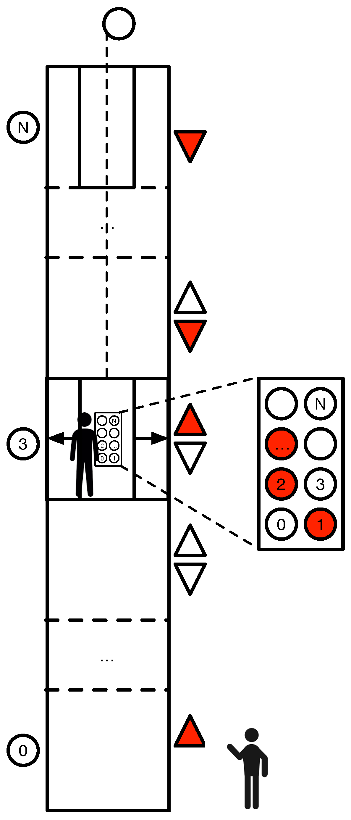
As shown in shown in Figure 3, the system controls a single-cabin elevator that travels up and down in a building with a set number of floors. The system requirements are summarised in Table 2 [29].
Based on these system requirements, the system features are mapped to the hardware and software components, as shown in Table 3. This is a design choice and therefore it is subjective. Elevation controls the requirements of WINDING, UNWIDING. Physical doors are implemented to more closely simulate a real elevator. Moreover, there is an external cabin caller and floor buttons inside the cabin for positioning. The model is also equipped with a floor indicator to visualise the current position. Although not strictly required, the elevator also includes a path optimiser for a more efficient path planning.
6. Proposed Architecture
This section describes the proposed architecture for the elevator model, including hardware, mechanical and software perspectives.
6.1. Hardware Design
6.1.1. Mapping
For the elevator to take use of its features, relevant hardware and software must be included. For elevation (WINDING, UNWIDING), a stepper motor with a threaded rod is utilised. A mechanical switch indicates when the elevator hits the ground floor. For the doors, a servo motor is adopted. The floor buttons have sensors corresponding to each floor. The cabin caller is equipped with a potentiometer to externally select the floor, and with an LCD screen, also for floor indication. The path optimiser is ruled by a queuing system implemented via software. The complete mapping is shown in Table 3.

Table 3.
Mapping table for the elevator model.
| Feature | Hardware | Software | |
|---|---|---|---|
| Sensors | Actuators | ||
| Elevation | Ground floor switch | Stepper with threaded rod | |
| Doors | Servo | ||
| Floor buttons inside cabin | Button (7-2) | ||
| Floor indicator | LCD-Screen | ||
| Cabin-caller | Potentiometer for selection, buttons (1-0) for up and down | LCD-Screen | |
| Path-optimizer | Queueing system | ||
6.1.2. Connection to All in One Servo Lab (AIOSL)
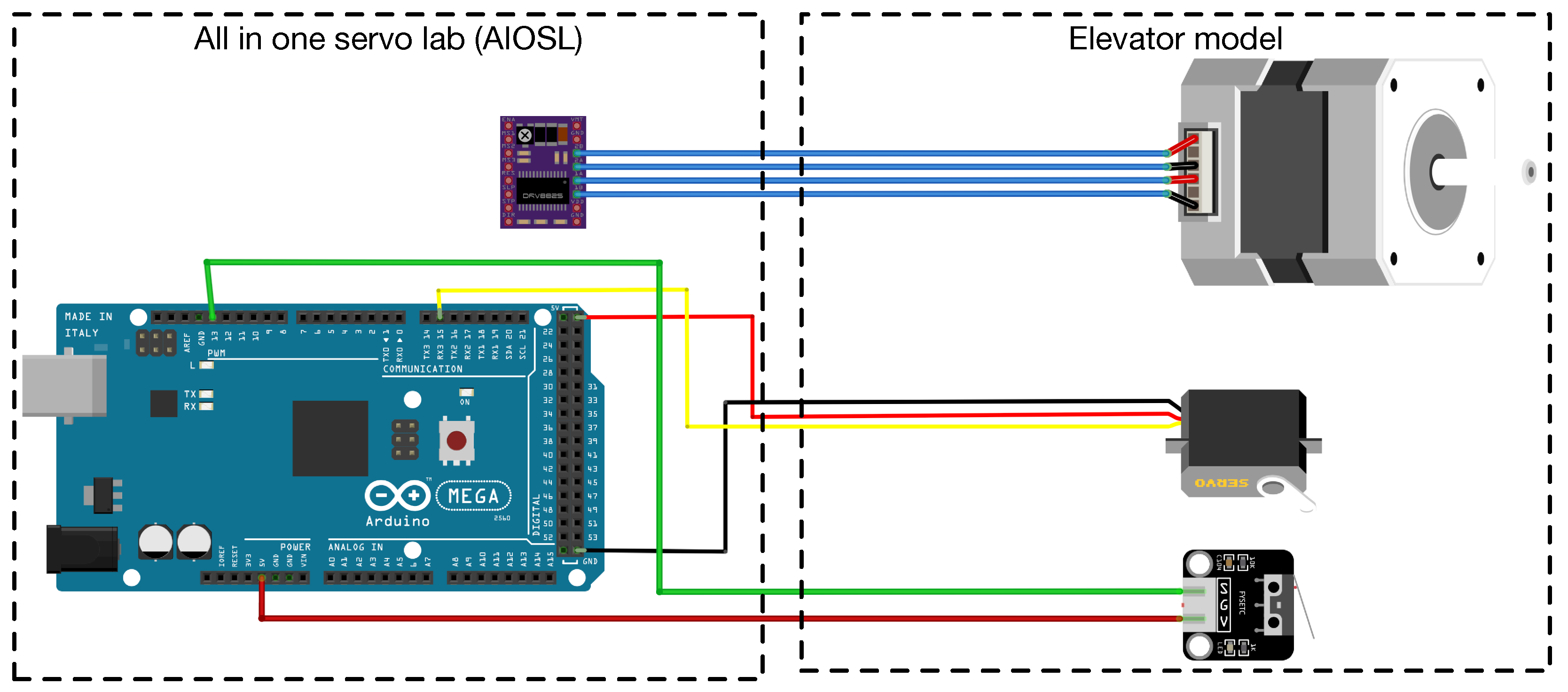
Wires are connected on a stand to the stepper, ground switch and servo wire. These wires go through the bottom of a printed skirt and are plugged into the AIOSL. The stepper motor is used in a four-pole configuration, although the hardware supports six poles. The AIOSL have a built-in stepper motor drive (DRV8813) for directional control [28] and a DAC (MCP4922) for control of the current, hence the torque of the motor. The stepper in the AIOSL is connected with a one-by-four female wire head, which makes it easy to switch it out with the wires coming from the elevator model. The schematic of the connection from the AIOSL to the elevator model is shown in Figure 4.
6.2. Mechanical Design
The model’s availability is a crucial consideration. Components and production methods that are readily available are used for the prototyping process. The floors are made in acrylic sheets, which are laser cut in the right shape. The elevator cabin including doors, the bottom skirt and a mounting spacer for the stepper motor are 3D printed. All metal parts are easily available off the shelf in hobby shops and some components in hardware stores.
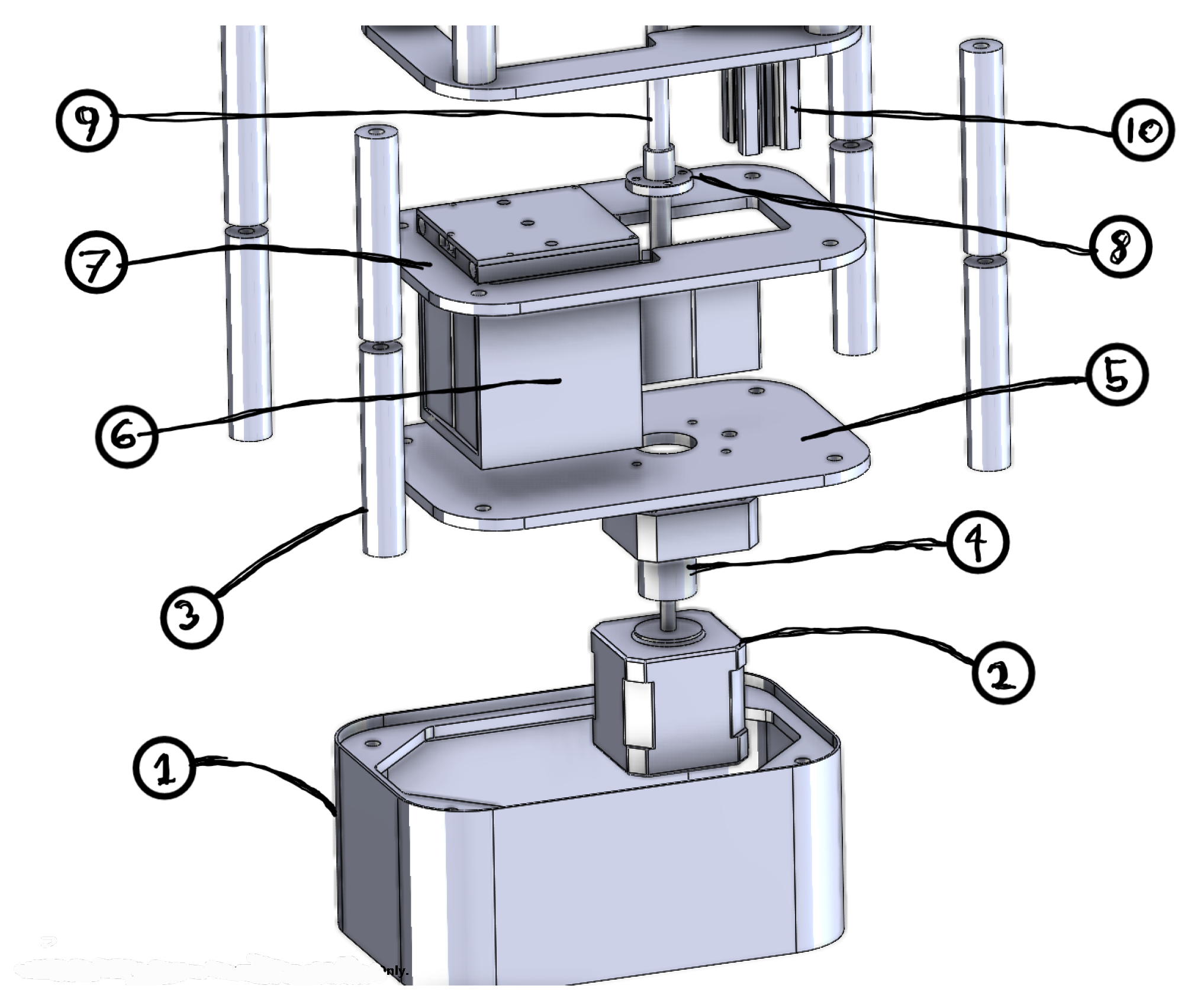
In Table 4, all the components needed for setting up the elevator model and integrating it with the AIOSL are described. An exploded view of the elevator model is shown in Figure 5. The threaded rod with a diameter of 8 mm is the type used for controlling the z-axis of 3D printers, and is usually available as a spare part in most stores selling 3D-printers. The M5 is a standardised threaded rod, and four of them are used for holding the assembly together. The V-slot is a standard RatRig profile. This part may be switched with most profile rods. Small adjustments of the profile on the elevator cabin to fit the selected profile would be necessary.
Assembly
The main tower part of the elevator model is assembled by first mounting the lock nuts at the end of four M5 threaded rods, and placed in the corner holes from the underside of the stand. The bottom floor plate is then threaded on the rods and placed down in the fitted area in the stand. The stepper is then mounted from the underside with the M3 bolts through the bottom plate and the stepper spacer. This is done to make sure that the shaft has the correct height above the plate for the flex axle to be mounted. The ground switch is mounted on the side of the spacer with two screws entered through pre-made holes, making sure that the switch is triggered by the elevator at the bottom floor. Finally the V-profile is attached to the bottom plate with a 5 mm screw from the bottom in a crescent shaped trail on the stepper spacer.
The rest of the floors are then assembled by putting a spacer on each rod and a mid floor section. This is repeated six times creating all the floors. The assembled elevator cabin is then slipped on to the profile and screwed down into the lead nut. Finally, the short spacers are mounted on the rods followed by the top plate, which is secured with two nuts on each rod.
The elevator cabin consists of a main body, two doors and a top section, containing the door mechanism and a servo. The door mechanism is operated by a servo pulling a fishing line through guiding poles on the doors, which again are held up by two rubber bands. The assembly is mounted to the cabin body with four M2 machine screws. The servo is connected by a servo wire through a hole at the bottom two mid plates and then the bottom plate.
6.3. Software Design
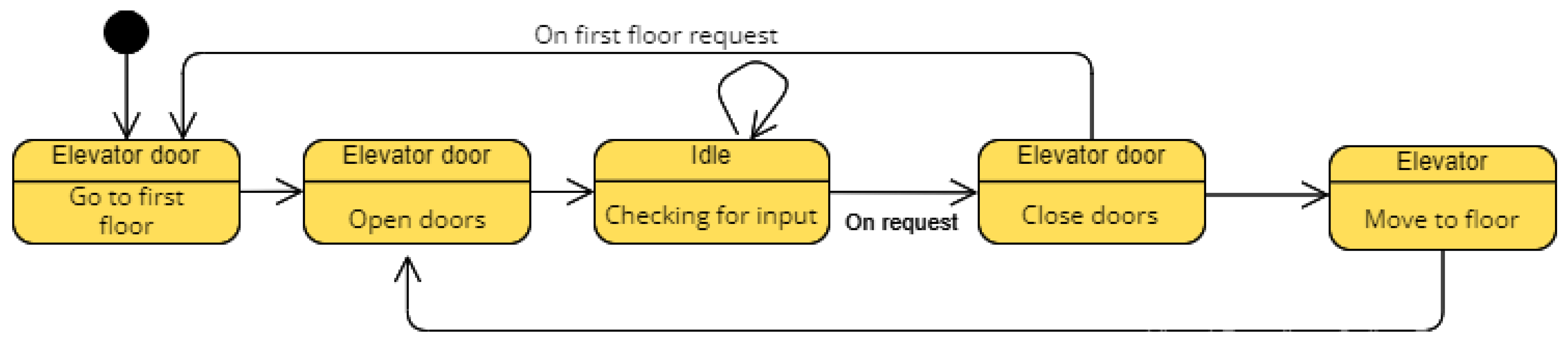
The development of the software is based on the requirements for the elevator. A state machine diagram is shown in Figure 6 to highlight the wanted response from the elevator, based on its input.
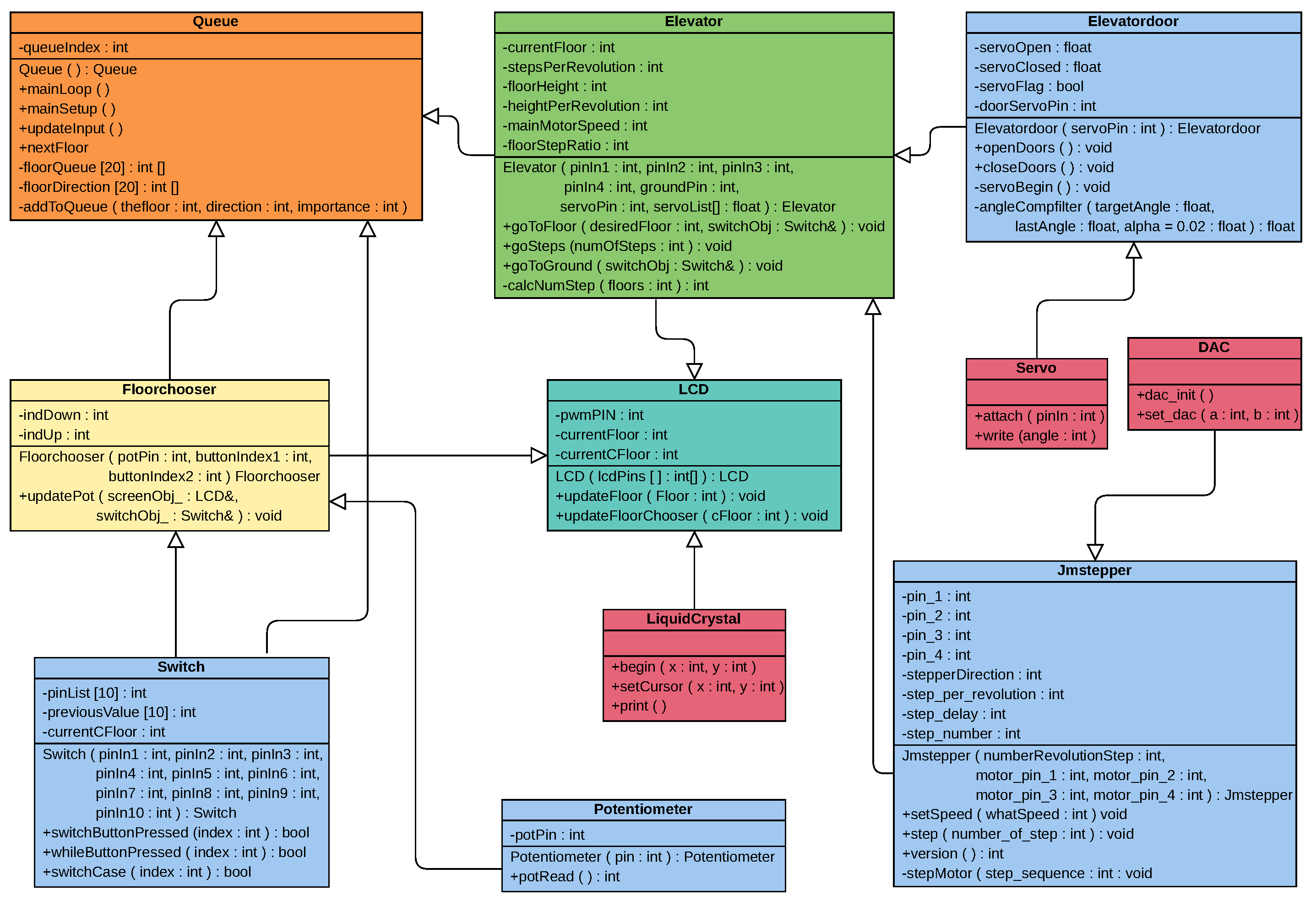
In Figure 7, the UML Class Diagram of the elevator model is depicted. The Servo and the LiquidCrystal libraries are third-party libraries, and are available as standard in the Arduino IDE. The “DAC” class is specialised for using the DAC unit, which controls the current connected to the stepper driver. This is necessary because of the old type of stepper driver implemented in the AIOSL. A similar explanation applies for the “Jmstepper” class too, as this is meant for a driver where the coils are activated separately. The remaining classes are created to accommodate the remaining specifications. The “Elevatordoor” class steers the door servo and keeps track of its current state simultaneously as it stores the set boundaries for the door. The “Switch” class is used to set up multiple switch inputs as elevator cabin buttons, as well as the floor buttons on the outside. These two are passed along to the “Floorchooser” class, which together with the “Potensiometer” class, passes the selected floor for the queue if up or down buttons are pushed. Note that the “Elevator” class controls a single elevator object. The advantage of keeping this as an object is the scalability of the code. With minor rewriting of the main control program, several elevator objects could be included for more efficiency. The “Elevator” class is connected to both the “Elevatordoor” and “Jmstepper” class, as well as the “LCD” class. As the “LCD” class is used in both “Elevator” and “Floorchooser”, the LCD object has to be created in the main control process and provided for both classes.
6.4. The Queuing Operator
The “Queue” class is a queuing operator and makes up the core of the program. It handles the input from the switch and the “Floorchooser” class by indexing the floor request in a list. In addition, the direction of the request is saved in a second list. Requests queued from the cabin buttons are prioritised and put at the front, while requests from the buttons at each floor are put at the end. Furthermore, the next floor (which is sent to the “Elevator” class) is chosen based on a range of requirements. The first object in the list is used as a reference point, and the rest of the queue is searched through. If a lower prioritised request is located between the current floor and the highest prioritised floor, this will be used as the new reference point. Based on the search, the next floor is passed to the “Elevator” class by the “nextFloor” function, as shown in Listing 1.
| Listing 1: The prioritising section of the “Queue” class. |
|
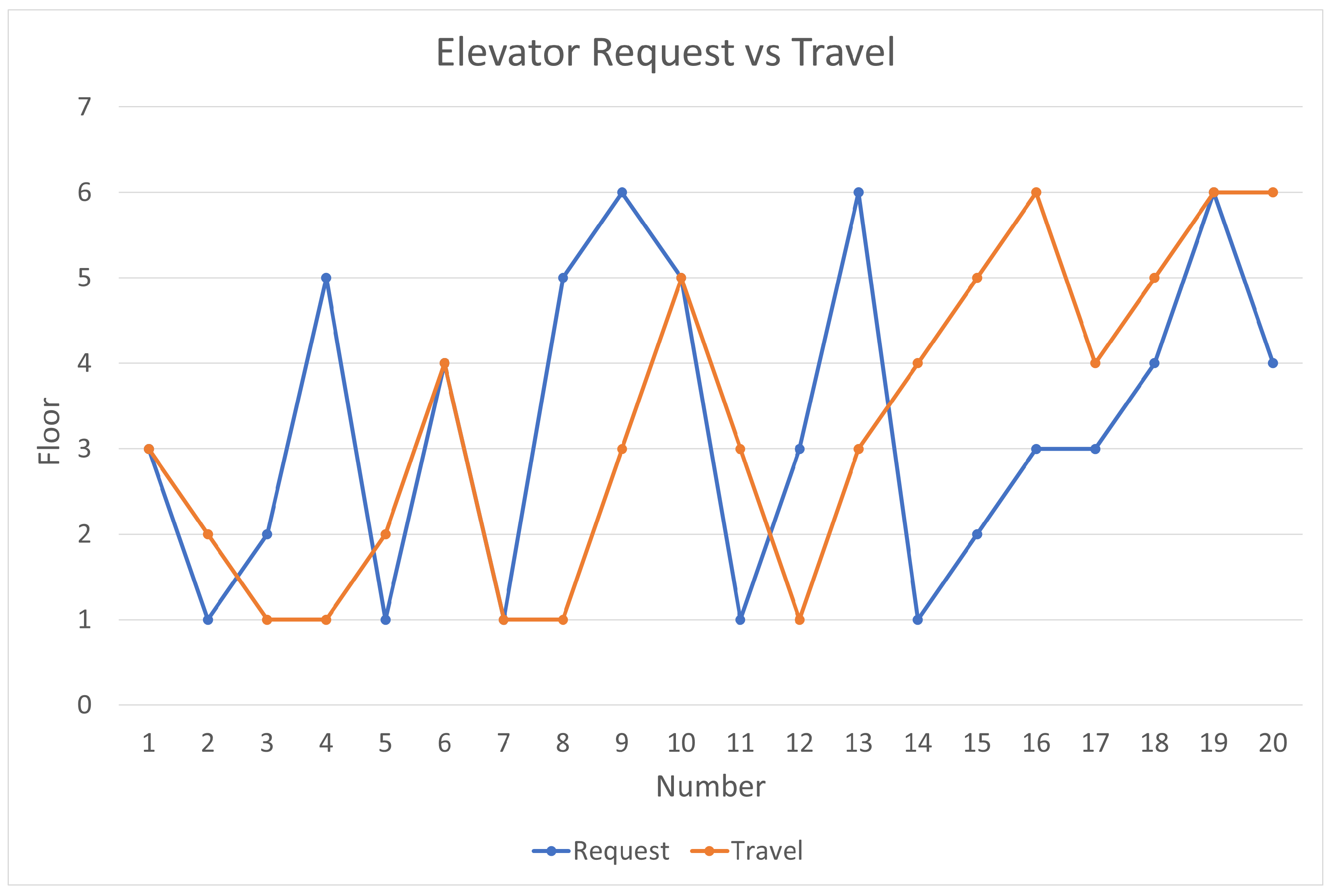
The result of a test with a pre-made queue provided for the optimiser code can be seen in Figure 8. The blue line represents the requested floor in the queue, and the orange line represents the travel of the cabin. In real-life operations, the queue would be updated simultaneously, which would affect the optimisation. Nevertheless, the test shows that the optimised path has less oscillation than the requested queue.
7. Course Learning Outcomes and Feedback from the Reference Group
Upon successful completion of the course, the student should: be able to apply methods for analysis and design of motion control systems; be able to explain the most commonly used components for such systems; be able to design and select components for this type of system; be able to design controls based on stability and accuracy requirements; be familiar with the microcontroller’s design and programming in C and be able to develop servo system control programs.
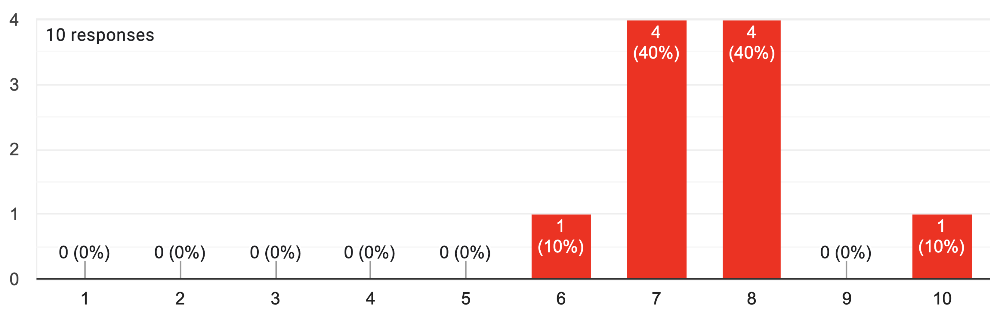
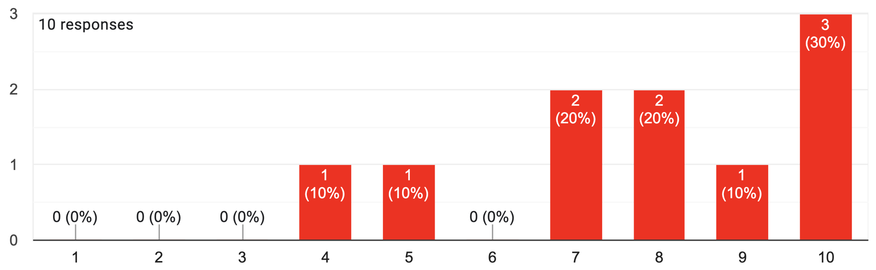
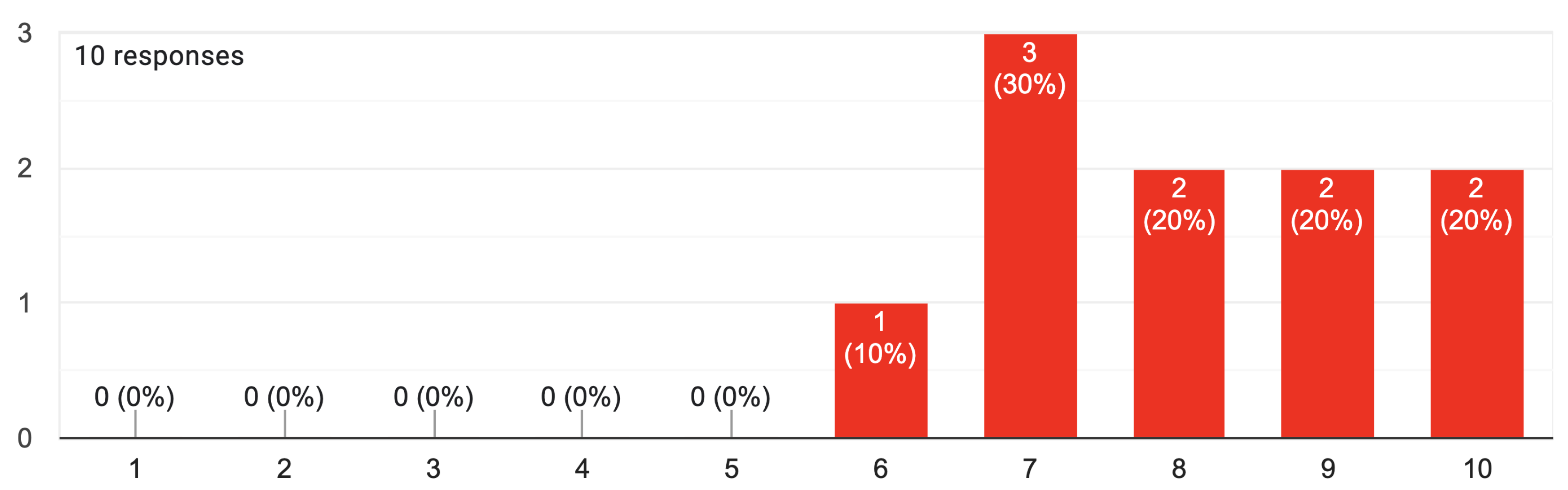
The usefulness of the proposed methodology for teaching motion control is confirmed by the collected students’ feedback in terms of engagement. The students consider the theoretical lectures quite engaging, as shown in Figure 9. Particularly positive is the students’ perception of the laboratory work, as shown in Figure 10. Equally well perceived by the students is the project work, as shown in Figure 11.
8. Conclusions and Future Work
This authors proposed a detailed syllabus of the motion control module for the engineering mechatronics education curriculum. The proposed module combines organised laboratory tasks with a number of structured theoretical sessions. The course culminates with a group project that focuses on the implementation of an elevator model. The students are engaged in a learning process that includes system-oriented, hardware-oriented, software-oriented, and application-oriented components of motion control systems in a highly integrated structure. The analysis of results from student surveys indicates that the course organisation and topics are compelling and helpful. In the future, this same educational approach could be applied to new modules for the engineering mechatronics education curriculum. Moreover, the possibility of integrating virtual reality (VR)/augmented reality (AR) with haptics into these modules for multi-sensory learning may be considered [30,31].
Author Contributions
Conceptualization, F.S. and M.O.; methodology, F.S.; software, M.Ø. and T.E.; validation, F.S.; formal analysis, F.S.; investigation, F.S., M.Ø. and T.E.; resources, F.S. and M.O.; data curation, M.Ø. and T.E.; writing—original draft preparation, F.S.; writing—review and editing, F.S., M.Ø. and T.E.; visualization, F.S., M.Ø. and T.E.; supervision, F.S. and M.O.; project administration, F.S.; funding acquisition, F.S. and M.O. All authors have read and agreed to the published version of the manuscript.
Funding
This work was supported by the Top Research Centre Mechatronics (TRCM), University of Agder (UiA), Norway.
Informed Consent Statement
Informed consent was obtained from all subjects involved in the study.
Data Availability Statement
Not applicable.
Conflicts of Interest
The authors declare no conflict of interest.
Abbreviations
The following abbreviations are used in this manuscript:
| AIOSL | All in one servo lab |
| PWM | Pulse–width modulation |
| IDE | Integrated development environment |
Appendix A
The elevator open source repository is available online at https://github.com/Microttus/Elevator-model/, accessed on 25 September 2022.
References
- Ma, J.; Li, X.; Tan, K.K. Advanced Optimization for Motion Control Systems; CRC Press: Boca Raton, FL, USA, 2020. [Google Scholar]
- Chung, W.K.; Fu, L.C.; Kröger, T. Motion control. In Springer Handbook of Robotics; Springer: Berlin, Germany, 2016; pp. 163–194. [Google Scholar]
- Sanfilippo, F.; Osen, O.L.; Alaliyat, S. Recycling A Discarded Robotic Arm For Automation Engineering Education. In Proceedings of the ECMS, Brescia, Italy, 27–30 May 2014; pp. 81–86. [Google Scholar]
- Sanfilippo, F.; Austreng, K. Enhancing teaching methods on embedded systems with project-based learning. In Proceedings of the IEEE International Conference on Teaching, Assessment, and Learning for Engineering (TALE), Wollongong, NSW, Australia, 4–7 December 2018; pp. 169–176. [Google Scholar]
- Sanfilippo, F.; Austreng, K. Sustainable Approach to Teaching Embedded Systems with Hands-On Project-Based Visible Learning. Int. J. Eng. Educ. 2021, 37, 814–829. [Google Scholar]
- University of Agder (UiA). Motion Control. 2022. Available online: https://www.uia.no/en/studieplaner/topic/MAS246-G (accessed on 7 March 2022).
- University of Agder (UiA). Feedback Control Systems 1. 2022. Available online: https://www.uia.no/en/studieplaner/topic/MAS239-G (accessed on 7 March 2022).
- University of Agder (UiA). Electrical Circuits and Digital Control. 2022. Available online: https://www.uia.no/en/studieplaner/topic/MAS134-G (accessed on 7 March 2022).
- University of Agder (UiA). Mathematics 1. 2022. Available online: https://www.uia.no/en/studieplaner/topic/MA-178-G (accessed on 7 March 2022).
- University of Agder (UiA). Mathematics 2. 2022. Available online: https://www.uia.no/en/studieplaner/topic/MA-179-G (accessed on 7 March 2022).
- University of Agder (UiA). Bachelor’s Programme in Mechatronics. 2022. Available online: https://www.uia.no/en/studieplaner/programme/INGMASK3 (accessed on 7 April 2022).
- Fowler, M. UML Distilled: A Brief Guide to the Standard Object Modeling Language; Addison-Wesley Professional: Boston, MA, USA, 2004. [Google Scholar]
- Henzinger, T.A.; Sifakis, J. The discipline of embedded systems design. Computer 2007, 40, 32–40. [Google Scholar] [CrossRef]
- Arduino. Arduino. 2022. Available online: https://www.arduino.cc/ (accessed on 7 April 2022).
- Sanfilippo, F.; Pacchierotti, C. A wearable haptic system for the health monitoring of elderly people in smart cities. Int. J. Online Eng. 2018, 14, 1–15. [Google Scholar] [CrossRef]
- Parate, S.; Lanjewar, S.; Dethe, R.; Hiwarkar, C. Four Quadrant Speed Control of DC Motor with Microcontroller ATmega 328 (Arduino Uno). Int. J. Res. Eng. Sci. Manag. 2020, 3, 62–65. [Google Scholar]
- Elanakova, V. Open-loop Control Algorithms for Stepper Motors. In Proceedings of the Aspire to Science, Novosibirsk, Russia, 18 April 2019; pp. 60–65. [Google Scholar]
- Tun, Z.M.; Naing, T.L. Double loop control of H-bridge DC chopper fed permanent magnet DC motor drives using low cost hardware. Int. J. Elect. Comput. Eng. 2018, 12, 857–866. [Google Scholar]
- The MathWorks, Inc. Six-Step Commutation of BLDC Motor Using Sensor Feedback. 2022. Available online: https://www.mathworks.com/help/mcb/gs/six-step-commutation-bldc-motor-using-position-sensor.html (accessed on 7 April 2022).
- Yuniarto, M.; Rijanto, E.; Mukhlisin, A. Design and Performance Analysis of Brushless Direct Current (BLDC) Motor Controller for Electric Scooter. In Proceedings of the IOP Conference Series: Materials Science and Engineering, Jakarta, Indonesia, 9–10 October 2019; Volume 694, p. 012004. [Google Scholar]
- Wang, G.; Valla, M.; Solsona, J. Position sensorless permanent magnet synchronous machine drives—A review. IEEE Trans. Ind. Electron. 2019, 67, 5830–5842. [Google Scholar] [CrossRef]
- Celik, H.; Yigit, T. Field-oriented control of the PMSM with 2DOF PI controller tuned by using PSO. In Proceedings of the IEEE International Conference on Artificial Intelligence and Data Processing (IDAP), Malatya, Turkey, 28–30 September 2018; pp. 1–4. [Google Scholar]
- O’Rourke, C.J.; Qasim, M.M.; Overlin, M.R.; Kirtley, J.L. A geometric interpretation of reference frames and transformations: dq0, clarke, and park. IEEE Trans. Energy Convers. 2019, 34, 2070–2083. [Google Scholar] [CrossRef] [Green Version]
- Singh, A.K.; Das, M.; Basumatary, D.; Roy, G. A Review note on Compensator Design for Control Education and Engineering. Int. J. Eng. Res. Technol. 2014, 3, 2493. [Google Scholar]
- Plaza, P.; Sancristobal, E.; Carro, G.; Blazquez, M.; García-Loro, F.; Martin, S.; Perez, C.; Castro, M. Arduino as an educational tool to introduce robotics. In Proceedings of the IEEE International Conference on Teaching, Assessment, and Learning for Engineering (TALE), Wollongong, NSW, Australia, 4–7 December 2018; pp. 1–8. [Google Scholar]
- Adel, Z.; Hamou, A.A.; Abdellatif, S. Design of Real-time PID tracking controller using Arduino Mega 2560for a permanent magnet DC motor under real disturbances. In Proceedings of the IEEE International Conference on Electrical Sciences and Technologies in Maghreb (CISTEM), Algiers, Algeria, 28–31 October 2018; pp. 1–5. [Google Scholar]
- Larman, C.; Basili, V.R. Iterative and incremental developments. a brief history. Computer 2003, 36, 47–56. [Google Scholar] [CrossRef]
- Hørthe, A.; Nødland, H.; Preus-Olsen, B. All in One Servo Lab, ArduinoTM-Based Laboratory Platform for Microcontroller Operated Servo Systems; University of Agder (UiA): Grimstad, Norway, 2019. [Google Scholar]
- Hoang, T.S. An Elevator System—Requirements Document. 2022. Available online: https://eprints.soton.ac.uk/422715/2/elevator_requirements.pdf (accessed on 7 April 2022).
- Sanfilippo, F.; Blazauskas, T.; Salvietti, G.; Ramos, I.; Vert, S.; Radianti, J.; Majchrzak, T.A.; Oliveira, D. A Perspective Review on Integrating VR/AR with Haptics into STEM Education for Multi-Sensory Learning. Robotics 2022, 11, 41. [Google Scholar] [CrossRef]
- Sanfilippo, F.; Blažauskas, T.; Girdžiūna, M.; Janonis, A.; Kiudys, E.; Salvietti, G. A multi-modal auditory-visual-tactile e-learning framework. In Proceedings of the International Conference on Intelligent Technologies and Applications, Grimstad, Norway, 11–13 October 2021; Springer: Cham, Switzerland, 2022; pp. 119–131. [Google Scholar]
Figure 1.
The proposed hands-on organisation of the motion control course.

Figure 2.
The all in one servo lab (AIOSL).

Figure 3.
An elevator system model with 0 to N floors, including a car, cables, an elevator machine, controls drive, cabin buttons and floor buttons.
Figure 3.
An elevator system model with 0 to N floors, including a car, cables, an elevator machine, controls drive, cabin buttons and floor buttons.

Figure 4.
Schematic of the connection from the AIOSL to the elevator model.

Figure 5.
Exploded view of the elevator model: (1) Bottom skirt, (2) Stepper motor, (3) Tube spacer, (4) Flex axle, (5) Bottom floor, (6) Cabin + Cabin door setup, (7) Mid floor, (8) Lead nut, (9) Threaded rod, (10) V-slot RatRig profile.
Figure 5.
Exploded view of the elevator model: (1) Bottom skirt, (2) Stepper motor, (3) Tube spacer, (4) Flex axle, (5) Bottom floor, (6) Cabin + Cabin door setup, (7) Mid floor, (8) Lead nut, (9) Threaded rod, (10) V-slot RatRig profile.

Figure 6.
UML state machine diagram for the elevator model.

Figure 7.
UML Class Diagram for the elevator model.

Figure 8.
The path of the requested path compared to the optimised path of the elevator.

Figure 9.
Feedback collected from students: on a scale of 1–10 with 1 being not engaging at all and 10 being extremely engaging, how engaging do you consider the theoretical lectures?
Figure 9.
Feedback collected from students: on a scale of 1–10 with 1 being not engaging at all and 10 being extremely engaging, how engaging do you consider the theoretical lectures?

Figure 10.
Feedback collected from students: on a scale of 1–10 with 1 being not engaging at all and 10 being extremely engaging, how engaging do you consider conducting the laboratory work?
Figure 10.
Feedback collected from students: on a scale of 1–10 with 1 being not engaging at all and 10 being extremely engaging, how engaging do you consider conducting the laboratory work?

Figure 11.
Feedback collected from students: on a scale of 1–10 with 1 being not engaging at all and 10 being extremely engaging, how engaging do you consider conducting the elevator project?
Figure 11.
Feedback collected from students: on a scale of 1–10 with 1 being not engaging at all and 10 being extremely engaging, how engaging do you consider conducting the elevator project?

Table 1.
The organisation of the course content.
| Lectures | Laboratory | Project |
|---|---|---|
| 12 lectures | 12 laboratories | elevator project |
Table 2.
System requirements.
| REQ 1 | The system controls the movement of an elevator. |
|---|---|
| REQ 2 | The number of floors is set. |
| REQ 3 | The elevator is either going up or going down. |
| REQ 4 | The elevator is driven by a motor which can be either WINDING, UNWIDING, or STOPPED. |
| REQ 5 | If not at the top floor, the cabin moves up one floor if the motor is WINDING |
| REQ 6 | If not at the bottom floor, the cabin moves down one floor if the motor is UNWINDING |
| REQ 7 | The cabin has a door which can be OPEN, HALF, or CLOSED. |
| REQ 8 | While the cabin is moving, its door must be closed. |
| REQ 9 | On each floor except the top one, there is an “up” button. |
| REQ 10 | On each floor except the bottom one, there is a “down” button. |
| REQ 11 | Inside the cabin, there are floor buttons, one for each floor. |
| REQ 12 | The cabin stops at a particular floor and opens the door if there is a request to serve at that particular floor. |
| REQ 13 | The requests at one floor are cleared once the door is fully open. |
| REQ 14 | The elevator should not move to leave a floor if there are requests to serve at that floor. |
| REQ 15 | The elevator should stay stationary at a floor when there are no requests. |
| REQ 16 | The elevator can only change direction if it has no requests in the same direction but has some requests in the opposite direction. |
Table 4.
Mechanical components for the elevator model.
| Article | Material | Size | Qty. | Comment |
|---|---|---|---|---|
| Threaded rod | Steel | Ø 8 mm–470 mm | 1 | |
| Lead nut | Brass | Hole 8 mm | 1 | |
| V-slot Rat Rig profile | Aluminium | 20 × 20 × 500 mm | 1 | |
| Threaded rod | Steel | M5-500 mm | 4 | |
| Nut | Steel | M5 | 8 | |
| Flex axle | Steel | 3 mm–8 mm | 1 | |
| Lock nut | Steel | 5 mm | 4 | |
| Tube spacer | PLA | 70 mm | 24 | 3D-printed |
| Short tube spacer | PLA | 25 mm | 4 | 3D-printed |
| Stepper spacer | PLA | 42 × 42 × 18 mm | 1 | 3D-printed |
| Bottom skirt | PLA | 152 × 102 × 68 mm | 1 | 3D-printed |
| Cabin + cabindoor setup | PLA | 1 | 3D-printed | |
| M3 machine screw | Steel | 4 | ||
| Bottom floor | Acrylic | 150 × 100 × 4 mm | 1 | Laser cut |
| Mid floor | Acrylic | 150 × 100 × 4 mm | 6 | Laser cut |
| Top floor | Acrylic | 150 × 100 × 4 mm | 1 | Laser cut |
| Door servo | 1 | |||
| Stepper motor | 1 | 17HS4401 | ||
| Wires |
Publisher’s Note: MDPI stays neutral with regard to jurisdictional claims in published maps and institutional affiliations. |
© 2022 by the authors. Licensee MDPI, Basel, Switzerland. This article is an open access article distributed under the terms and conditions of the Creative Commons Attribution (CC BY) license (https://creativecommons.org/licenses/by/4.0/).
Share and Cite
MDPI and ACS Style
Sanfilippo, F.; Økter, M.; Eie, T.; Ottestad, M. Teaching Motion Control in Mechatronics Education Using an Open Framework Based on the Elevator Model. Machines 2022, 10, 945. https://0-doi-org.brum.beds.ac.uk/10.3390/machines10100945
AMA Style
Sanfilippo F, Økter M, Eie T, Ottestad M. Teaching Motion Control in Mechatronics Education Using an Open Framework Based on the Elevator Model. Machines. 2022; 10(10):945. https://0-doi-org.brum.beds.ac.uk/10.3390/machines10100945
Chicago/Turabian StyleSanfilippo, Filippo, Martin Økter, Tine Eie, and Morten Ottestad. 2022. "Teaching Motion Control in Mechatronics Education Using an Open Framework Based on the Elevator Model" Machines 10, no. 10: 945. https://0-doi-org.brum.beds.ac.uk/10.3390/machines10100945
Note that from the first issue of 2016, this journal uses article numbers instead of page numbers. See further details here.