Article

Analysis of Load Inhomogeneity of Two-Tooth Difference Swing-Rod Movable Teeth Transmission System under External Excitation

1
School of Mechanical Engineering, Yanshan University, Qinhuangdao 066004, China
2
Parallel Robot and Mechatronic System Laboratory of Hebei Province, Yanshan University, Qinhuangdao 066004, China
*
Author to whom correspondence should be addressed.
Submission received: 6 May 2022 / Revised: 16 June 2022 / Accepted: 20 June 2022 / Published: 22 June 2022

Abstract

:
In order to improve the load state of the two-tooth difference swing-rod movable teeth transmission system, in this paper, a dynamic equivalent calculation model of the transmission system is established based on lumped parameter theory, and then a calculation method of system dynamic load is derived. The influence of external excitation on load inhomogeneity of the transmission system is analyzed from a dynamic point of view. The theoretical results are verified by Adams dynamic load simulation analysis and strain test based on a test bench. The results show that when errors of the transmission system are fixed, the system load inhomogeneity is improved effectively with the increase of load torque, while the system load inhomogeneity becomes worse as input speed increases. This study provides a theoretical reference for improving the load inhomogeneity of the two-tooth difference swing-rod movable teeth transmission system.

1. Introduction

A two-tooth difference swing-rod movable teeth transmission system has strong bearing capacity because of the multi-tooth meshing characteristics [1]. The structure of wave generator is symmetrical so that the symmetrical meshing pairs have strong self-balance and stable dynamic performance. In addition, the symmetrical meshing pair forces are balanced in the multi-tooth meshing process [2]. Under real conditions, the load inhomogeneity of symmetrical meshing pairs is obvious due to various excitation factors. Furthermore, the excitation factors can cause system vibration, fatigue failure of tooth surface, and damage to movable teeth. The consequences seriously affect the performance of the transmission system [3]. Under the condition of certain system errors, the influence of external excitation on the load inhomogeneity of the two-tooth difference swing-rod movable teeth transmission system cannot be ignored.
At present, research papers on the swing-rod movable teeth transmission mainly focus on tooth shape analysis [4], tolerance design [5], dynamic characteristics [6,7,8], strain analysis [9], and so on. Most of the studies on load inhomogeneity of transmission system are about planetary gear transmission. Taking the concentric face gear split-torque transmission system (CFGSTTS) as the study object, Dong et al. [10] analyzed the characteristics of dynamic load sharing by establishing a lumped parameter model according to the Newton theorem. Dong et al. [11] studied the load-sharing characteristics of face-gear four-branching split-torque transmission system by establishing a static load-sharing mechanical analysis model. Using the surface gear flow system as the research object, Mo et al. [12] studied the change curves of meshing force and load-sharing coefficient, and analyzed the effects of input power and input speed on the load-sharing coefficient of the system. Hu et al. [13] analyzed the influence of meshing impact on the load-sharing coefficients and dynamic load factors of the planetary transmission system. Taking the large-scale wind power planetary gear system as the research object, Xu et al. [14] studied the effect of external load changes on the system load sharing through finite element simulation analysis and experimental tests. Zhang et al. [15] introduced single factor analysis to investigate the influence of each nonlinear internal excitation on the load-sharing coefficient (LSC) and determined the most significant control factors affecting LSC. On this basis, Zhang et al. [16] proposed a dynamic tooth wear prediction model and studied the influence of tooth wear on load sharing. Bodas et al. [17] simulated the effects of carrier and gear errors associated with manufacturing and assembly on load sharing between planetary gears by using the finite element method. Sanchez-Espiga et al. [18] proposed a numerical method to calculate the load-sharing problem of the planetary transmission by measuring the strains of the root of the sun gear teeth. Taking two-stage planetary transmission as the study object, Sun et al. [19] proposed a numerical method to calculate dynamic sensitivity of the load-sharing coefficient to errors. The above studies systematically studied the influence of external excitation on the load inhomogeneity of the planetary transmission system, wherein the important influencing factors of external excitation were clarified and the simulation and experimental techniques were analyzed. The two-tooth difference swing-rod movable teeth transmission belongs to the planetary transmission with small tooth difference [20], but its internal structure is more complex. Therefore, it is more difficult to establish a dynamic model, conduct simulation modeling, and carry out test measurements.
In this paper, the two-tooth difference swing-rod movable teeth transmission system is taken as the research object. A dynamic equivalent calculation model is established. Combined with the relative displacement relationship of each component, dynamic differential equations of the system are derived to obtain the system dynamic load. Load proportional coefficients are used to evaluate the degree of the system load inhomogeneity. The influence of external excitation on system load inhomogeneity is investigated by theoretical calculation. Subsequently, the results are verified by simulation analysis and experimental tests, which provides a theoretical reference for improving the system load inhomogeneity.

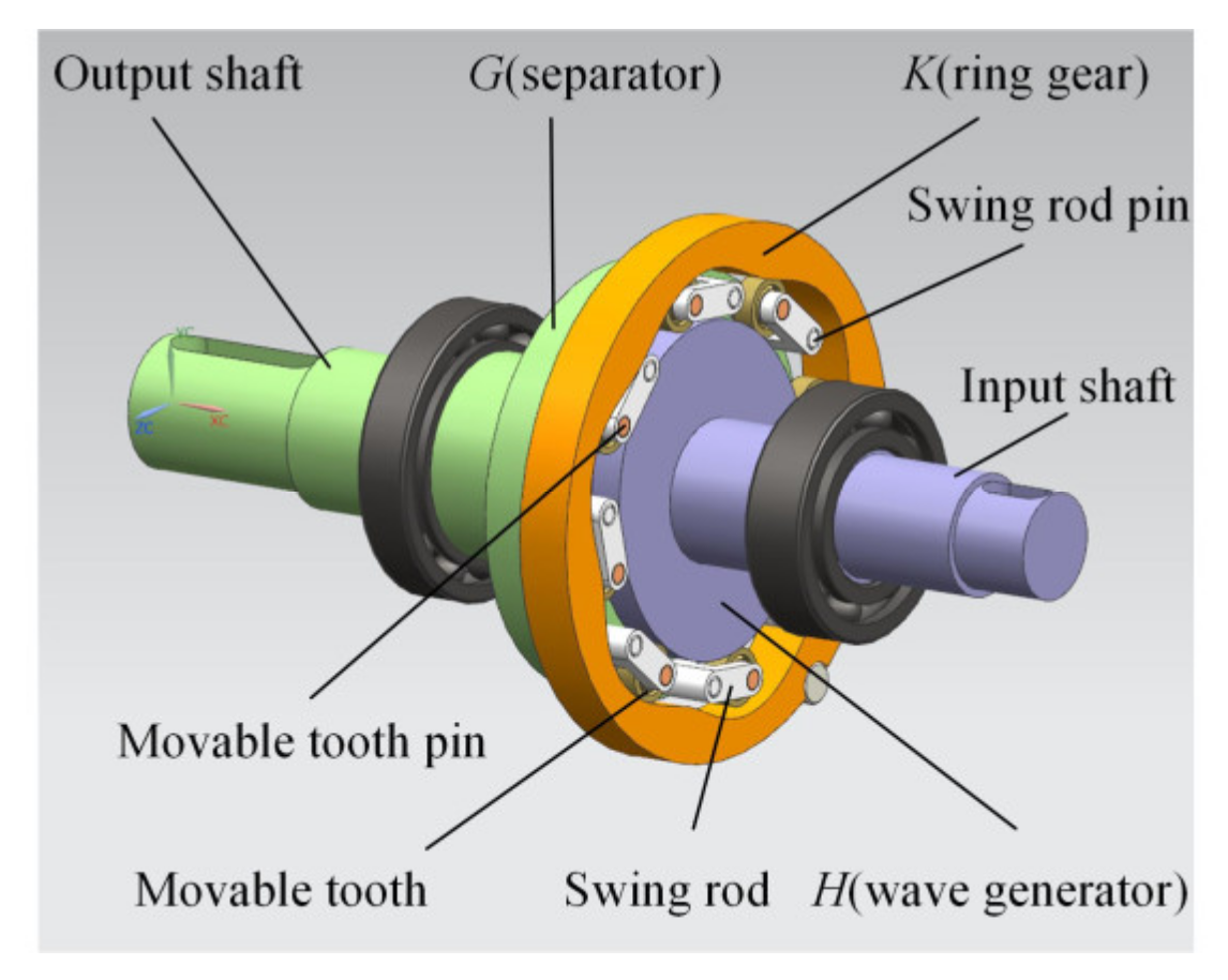
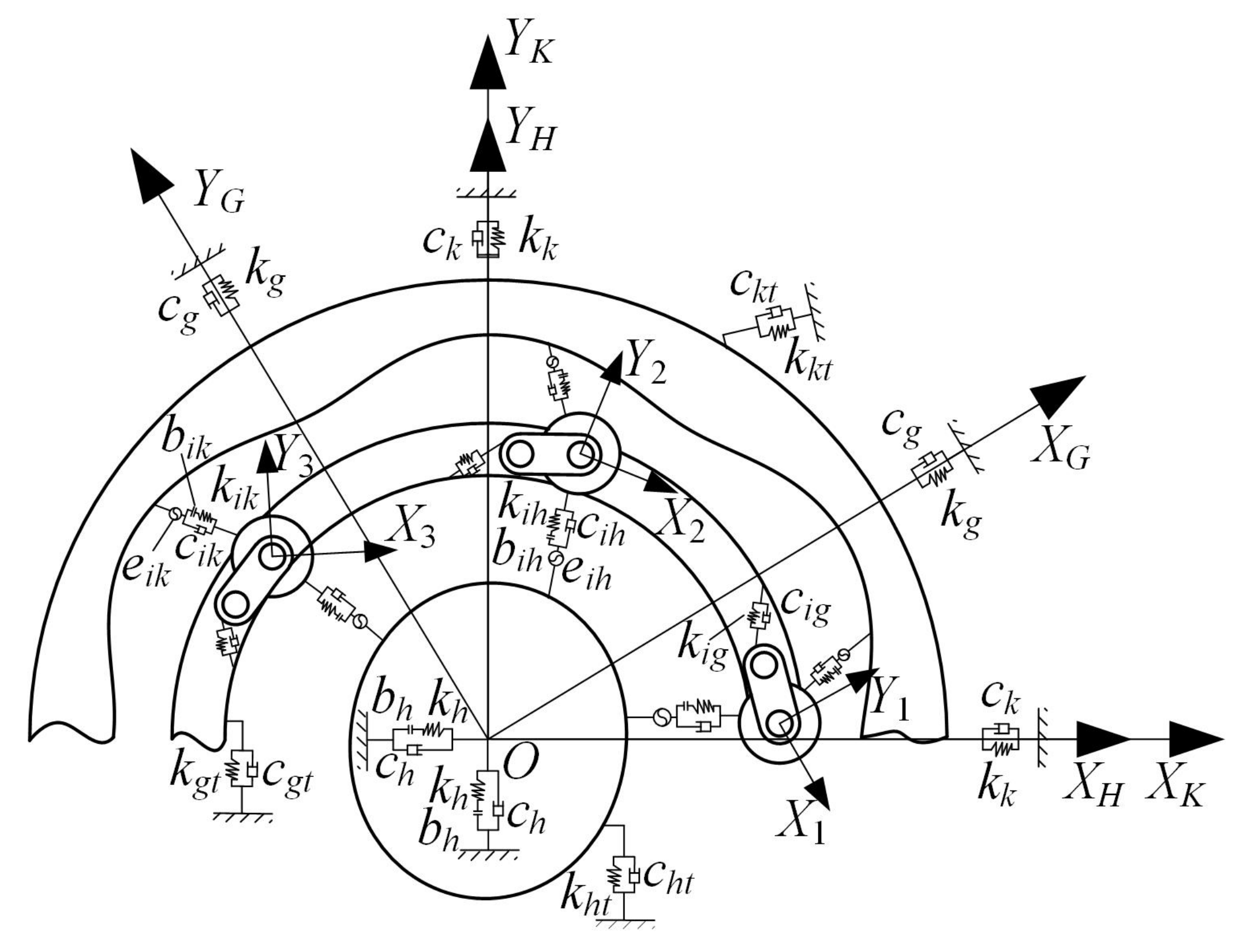
2. Equivalent Calculation Model

The two-tooth difference swing-rod movable teeth transmission system is shown in Figure 1. As a typical planetary transmission system with small tooth difference, the two-tooth difference swing-rod movable teeth transmission system consists of a wave generator H, a ring gear K, a separator G, swing rods, and movable teeth. In this case, the ring gear K is fixed. The wave generator H is fixed to the input shaft. The separator G is fixed to the output shaft. The input power of the wave generator H is transmitted to the separator G through multiple movable teeth which mesh with the wave generator H and the ring gear K at the same time.
In order to obtain the micro-displacement of each component in the transmission process, a dynamic equivalent calculation model (shown in Figure 2) is established based on the lumped parameter theory. The following assumptions are made. Firstly, only small elastic deformation occurs in the meshing pairs and bearings in the system. Secondly, all the components are regarded as units composed of dampers and springs; the flexible deformation caused by components can be ignored. Thirdly, each swing rod, movable tooth, swing rod pin, and movable tooth pin group is regarded as a whole, and the deformation and errors between them are ignored. In addition, the mass body is treated as rigid, and deformation occurs only in the spring elements and dampers.
The coordinate systems XHOYH, XKOYK, and XGOYG are fixedly connected with the wave generator, the ring gear, and the separator, respectively. XKOYK is the fixed absolute coordinate system; XHOYH and XGOYG are the relative coordinate systems rotating with the wave generator and separator, respectively. Xi and Yi are fixedly attached to the ith movable tooth (i = 1, 2, 3, …, n, where n represents the number of the movable teeth).
In the dynamic equivalent calculation model of the two-tooth difference swing-rod movable teeth transmission system, there are (9 + 3n) degrees of freedom.

3. Dynamic Load Calculation of the Transmission System

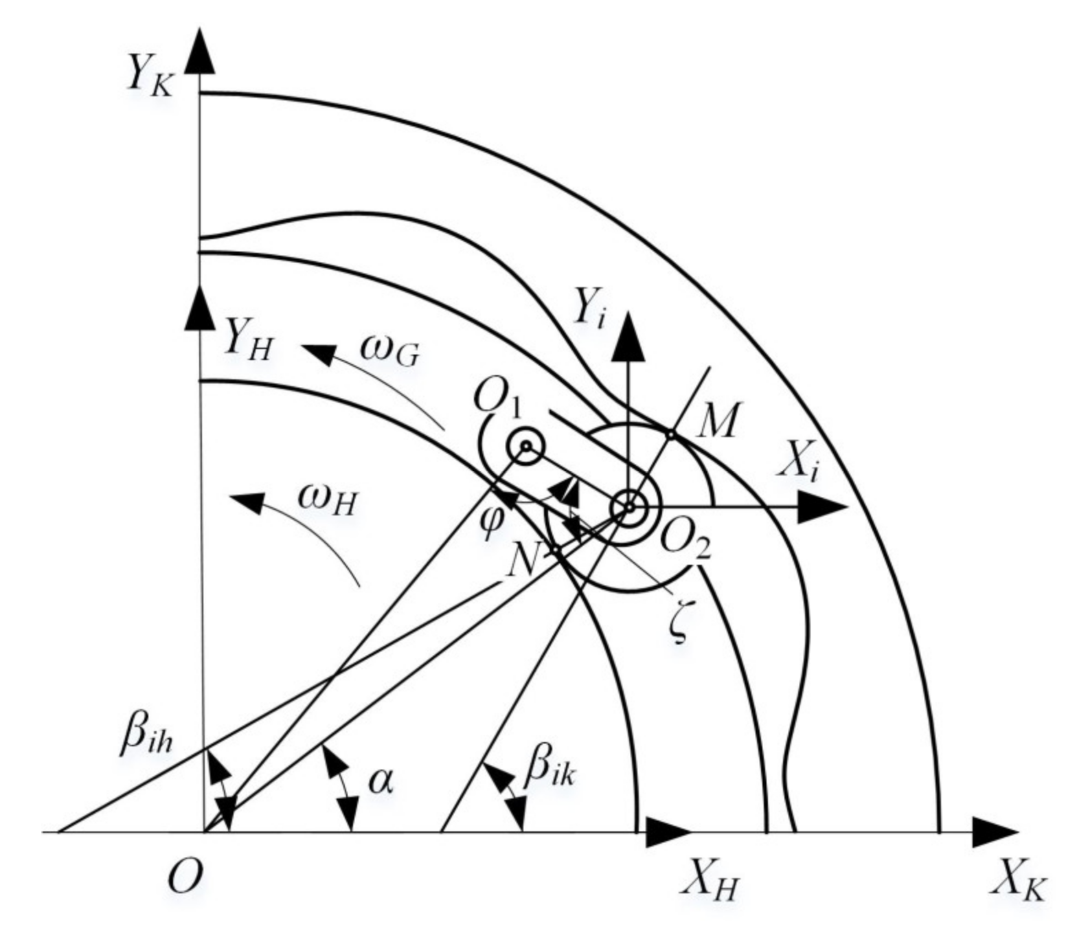
3.1. Relative Displacement and Differential Equation of Motion of the Transmission System

The dynamic load of the movable teeth transmission system is caused by the relative elastic displacements of the meshing points between the movable teeth and the wave generator and the meshing points between the movable teeth and the ring gear in their normal direction. They can be calculated according to the relationship between force and deformation.
To obtain the relative displacement relationship between the components in Figure 2, a relative displacement analysis model of the transmission system is established, as shown in Figure 3.
The direction of the meshing point pointing to the movable tooth center O2 is defined as the positive direction of relative displacement, and the displacements of the wave generator and the ring gear relative to the movable tooth are projected on the positive direction. Combined with Figure 2 and Figure 3, the relative displacements on each meshing line can be obtained as follows:
Δ i h = x h x i cos β i h + y h y i sin β i h u h sin α β i h u i cos π 2 ζ + α β i h e i h ,
Δ i k = x i x k cos β i k + y i y k sin β i k + u k sin α β i k + u i cos π 2 ζ + α β i k e i k ,
Δ i g = x i x g cos ζ α + y i y g sin ζ α + u g cos π 2 φ ,
The subscripts h, g, and k represent the wave generator, the separator, and the ring gear, respectively. i is the serial number of the movable tooth. Based on a transmission error model of the two-tooth difference swing-rod movable teeth transmission system, the equivalent meshing errors can be obtained by using the action line increment method [21].
In the working process of the two-tooth difference swing-rod movable teeth transmission system, the whole system is in a state of force balance. According to Newton’s second law, combined with Figure 2 and Figure 3, the wave generator, the ring gear, the separator, and the ith movable tooth subsystem are analyzed.
The dynamic differential equation of the wave generator, the separator, and the ring gear can be uniformly expressed as follows:
m p x ¨ p + c p x ˙ p + k p f x p , b p + i = 1 n c i p Δ ˙ i p + k i p f Δ i p , b i p a p x = 0 m p y ¨ p + c p y ˙ p + k p f y p , b p + i = 1 n c i p Δ ˙ i p + k i p f Δ i p , b i p a p y = 0 I p / r p 2 u ¨ p + c p t u ˙ p + k p t u p + i = 1 n c i p Δ ˙ i p + k i p f Δ i p , b i p a p u = F p ,
In Equation (4), f(Δ,b) is a symbolic function, which represents the relationship between the tooth clearance and the meshing displacement of the two-tooth difference swing-rod movable teeth transmission system. The equation is as follows:
f Δ , b = Δ b Δ > b 0 Δ b Δ + b Δ < b Δ b = 0 ,
The external force acting on the part p is
F p = T i n / r h p = h T o u t / r g p = g 0 p = k ,
The projection vector of the error excitation on the ring gear coordinate system is
( a p x , a p y , a p u ) T = cos β i h , sin β i h , sin α β i h T p = h cos ζ α , sin ζ α , cos π 2 φ T p = g cos β i k , sin β i k , sin α β i k T p = k ,
The dynamic differential equation of the ith movable tooth is
m i x ¨ i c i h Δ ˙ i h + k i h f Δ i h , b i h cos β i h + c i k Δ ˙ i k + k i k f Δ i k , b i k cos β i k c i g Δ ˙ i g + k i g Δ i g cos ζ α = 0 m i y ¨ i c i h Δ ˙ i h + k i h f Δ i h , b i h sin β i h + c i k Δ ˙ i k + k i g f Δ i k , b i k sin β i k + c i g Δ ˙ i g + k i g Δ i g sin ζ α = 0 I i / r i 2 u ¨ i c i h Δ ˙ i h + k i h f Δ i h , b i h cos π 2 ξ + α β i h + c i k Δ ˙ i k + k i k f Δ i k , b i k sin π 2 ζ + α β i k = 0 ,
According to the dynamic differential equation and the relative displacement of each component, considering the stiffness and damping of the system, the transverse and longitudinal vibration displacements of each component can be obtained via the Newmark method, which lays a foundation for the calculation of dynamic loads and load proportional coefficients between the movable teeth and the ring gear.

3.2. Calculation of Dynamic Load and Load Proportional Coefficient

In the two-tooth difference swing-rod movable teeth transmission system, it is assumed that the dynamic load between the ith movable tooth and the ring gear is Fki. According to Equations (2) and (5), and combined with the meshing stiffness between the ith movable tooth and the ring gear, the dynamic load Fki can be derived as
F k i = k i k f Δ i k , b i k ,
where kik can be calculated from the system deformation coordination conditions and the Palmgren deformation equation [22].
In the two-tooth difference swing-rod movable teeth transmission system, the load proportional coefficient is defined to measure the load inhomogeneity of the system, which means the ratio of the actual dynamic load borne by the two center-symmetric movable teeth in the load distribution. Under ideal conditions, the load proportional coefficient of two symmetrical movable teeth is 1. The larger the load proportional coefficient, the more serious the system load inhomogeneity. The instantaneous load proportional coefficient when the ith and jth movable teeth mesh with the ring gear can be expressed as
Ω k i j = 2 F k i F k i + F k j i = 1 , 2 , 3 , , n / 2 ,
where j = i + n/2.
In the transmission system, a movable tooth undergoes a complete lift and return motion in one meshing cycle. In order to characterize the extreme value of the load proportional coefficient, the maximum instantaneous load proportional coefficient in each meshing cycle is taken to represent the load proportional coefficient in this cycle. The maximum load proportional coefficient when the ith and jth movable teeth mesh with the ring gear in a meshing period can be expressed as
B k i = Ω k i j 1 max + 1 , i = 1 , 2 , 3 , , n

4. Analysis of the Influence of External Excitation on System Load Inhomogeneity

In order to study the influence of external excitation on the system load inhomogeneity, a prototype of the two-tooth difference swing-rod movable teeth transmission system was designed. Here, 45 steel was selected as the material of the wave generator, the separator, the ring gear, and the movable teeth. According to the design requirements, the machining accuracy of each component was selected as grade 7, and the clearances of the meshing pairs are 5 μm. The basic parameters of the transmission system are shown in Table 1.
In reality, the influence of external excitation on the system load inhomogeneity cannot be ignored. Therefore, it is necessary to explore the influence of load torque and input speed on the load inhomogeneity of the system, so as to guide the adjustment of the working state of the transmission system and make the load distribution of the system more uniform.

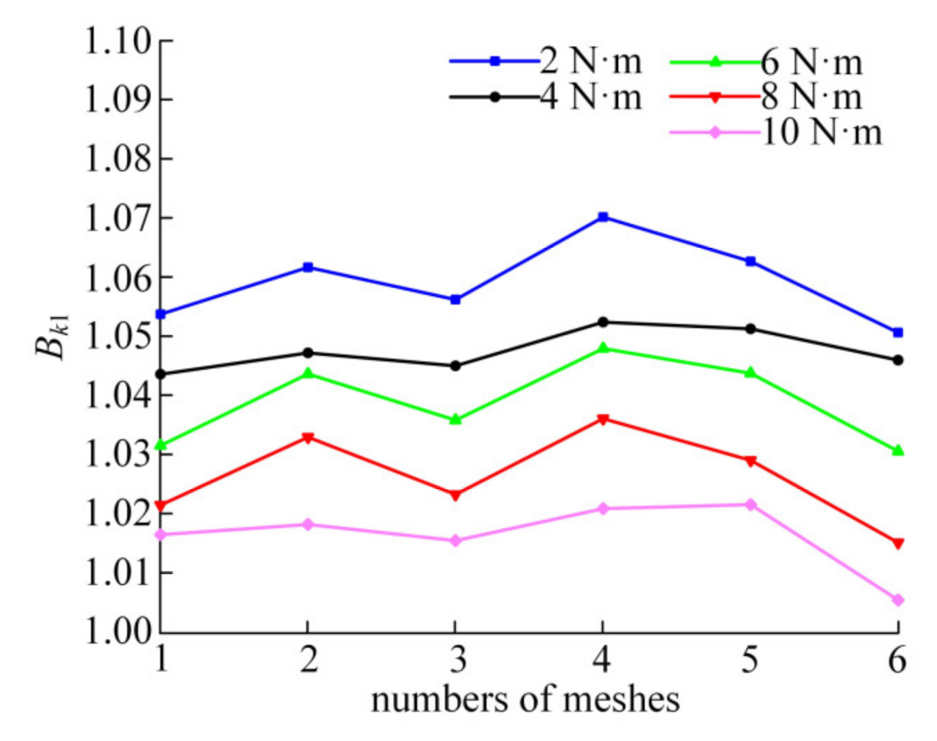
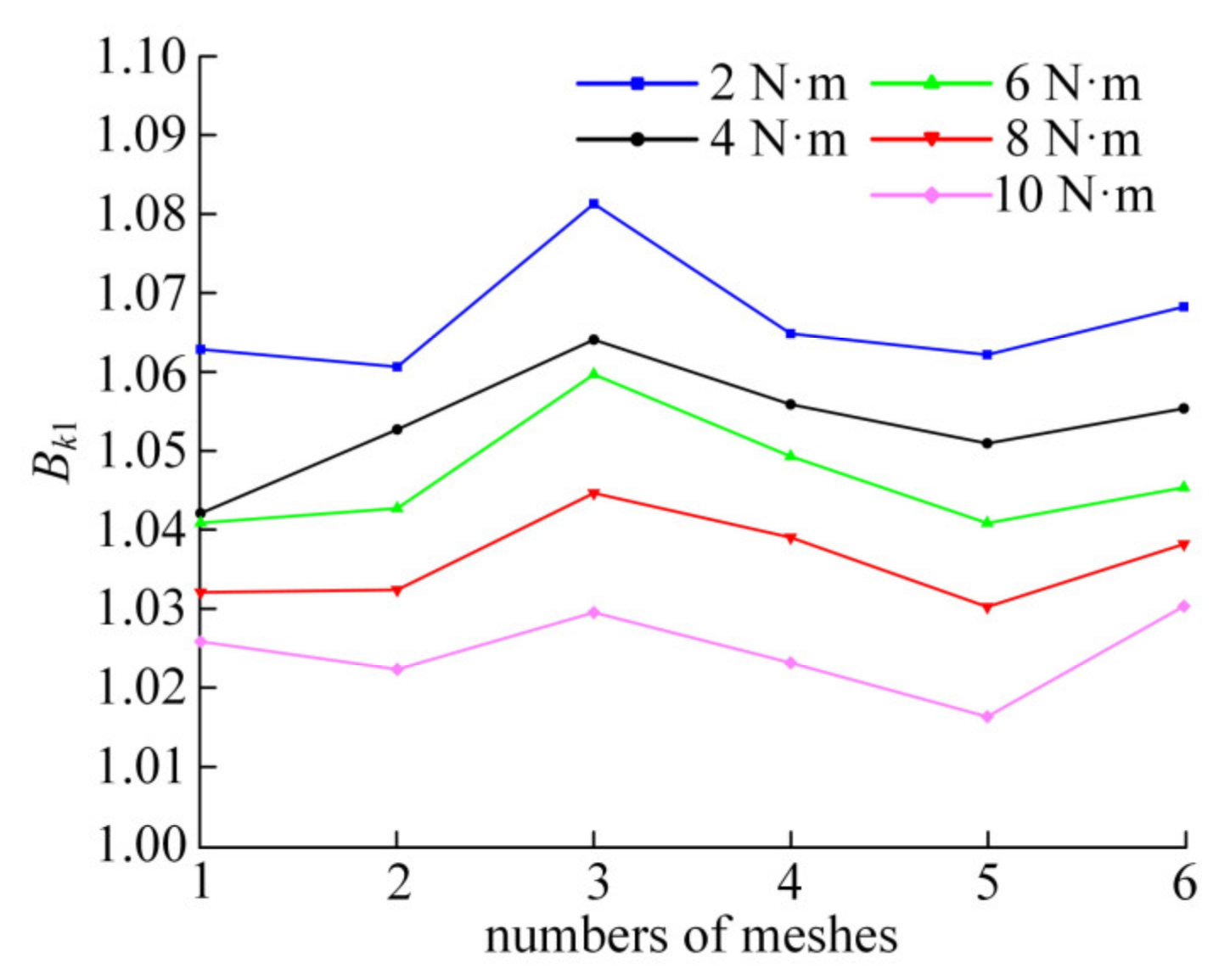
4.1. Influence of Load Torque on System Load Inhomogeneity

In order to study the influence of system load torque on the system load inhomogeneity, the input speed of the wave generator was set as 800 r/min, whilst other parameters remained unchanged. Using the first movable tooth and the symmetrical fifth movable tooth in the system as an example, the load proportional coefficients of the movable tooth with the ring gear under different load torques can be calculated by Equation (11). Making the separator rotate a circle, the load proportional coefficient curves of the movable tooth in six meshing cycles under the load torques of 2 N·m, 4 N·m, 6 N·m, 8 N·m, and 10 N·m can be obtained, as shown in Figure 4.
In Figure 4, with the increase of the load, the load proportional coefficient presents a downward trend. Under the same load, the load proportional coefficient fluctuates in a rotation cycle of the separator, which is caused by errors. However, due to the coupling effect of various errors and deformation, the variation of the load proportional coefficient does not show obvious periodicity. The average values of the load proportional coefficients Bk1 under different load torques are 1.0592, 1.0477, 1.039, 1.0265, and 1.0166, respectively. With the increase of system load torque, the average value of the load proportional coefficient Bk1 decreases. The average value can reflect the central tendency of the load proportional coefficient at a certain level. The larger the average value, the more serious the system load inhomogeneity. Therefore, it can be seen from Figure 4 that increasing the system load torque can make the system load distribution more uniform and improve the stability of the system.

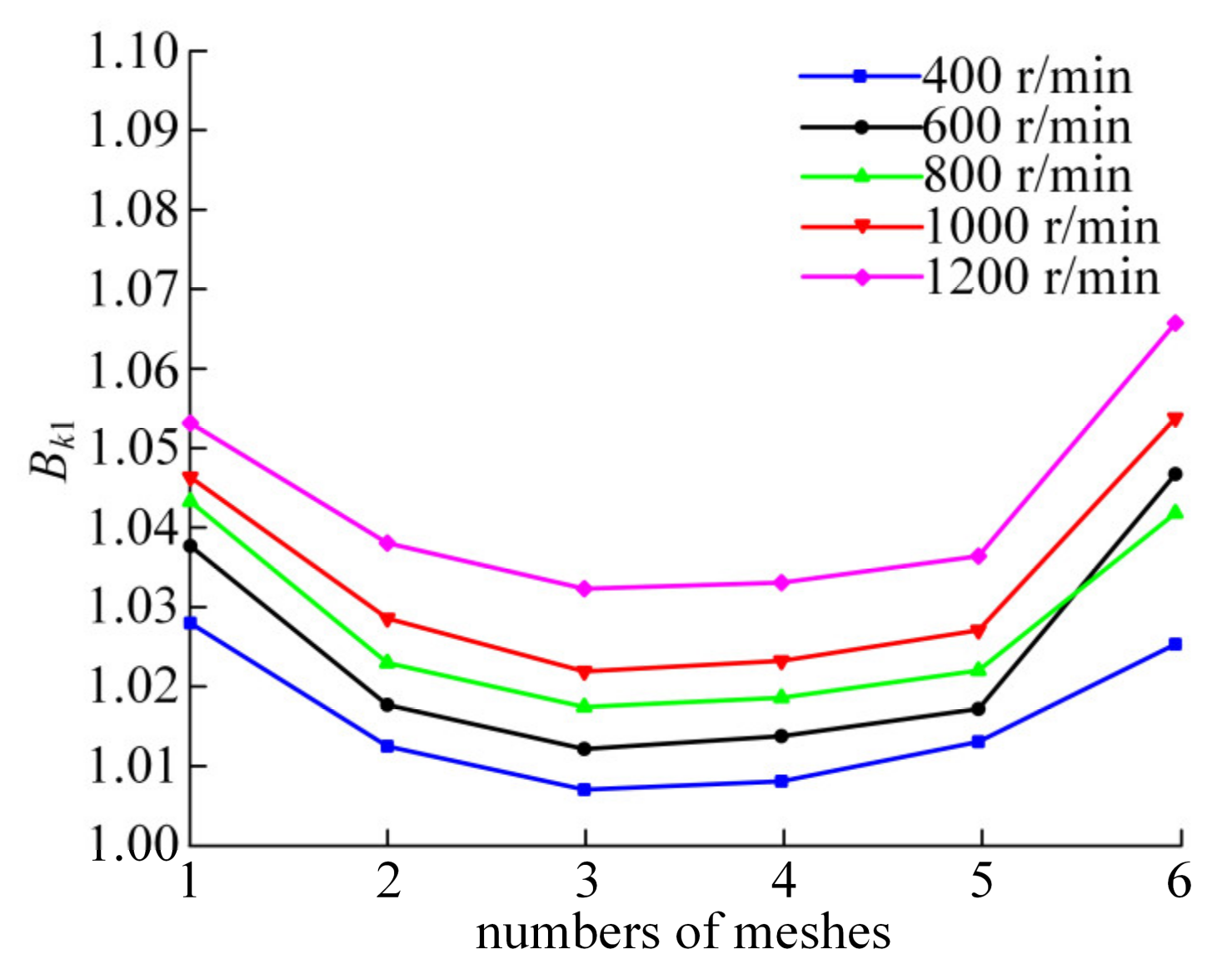
4.2. Influence of Input Speed on System Load Inhomogeneity

On the premise of keeping other basic parameters unchanged, the load torque of the separator was set as 10 N·m, and the influence of speed on system load inhomogeneity was studied. Using the first movable tooth and the symmetrical fifth movable tooth in the system as an example, the load proportional coefficient curves under the input speeds of 400 r/min, 600 r/min, 800 r/min, 1000 r/min, and 1200 r/min can be obtained, as shown in Figure 5.
In Figure 5, with the increase of the input speed, the load proportional coefficient presents an upward trend. In addition, it can be seen from the figure that the load proportional coefficient curve at 600 r/min intersects with that at 800 r/min. This may be due to the existence of error factors in the system, so that the system is not completely centrosymmetric. When the rotation speed reaches 600 r/min, the vibration displacement reaches the maximum in the sixth engagement, resulting in a large load proportional coefficient. The average values of the load proportional coefficients Bk1 are 1.0159, 1.0244, 1.0279, 1.0337, and 1.0433, respectively. With the increase in input speed, the average value of Bk1 also increases, and the system load inhomogeneity becomes more serious. This shows that the load uniformity of the two-tooth difference swing-rod movable teeth transmission system is better when working under low speed conditions.

5. Dynamic Load Simulation Analysis

In order to verify the influence of the load torque and input speed on system load inhomogeneity, a virtual prototype model of the transmission system was established in ADAMS to analyze the load proportional coefficient. Considering the actual working state of the prototype, the error accuracy level of the main components of the prototype model was selected as grade 7, and the error accuracy level of the other components was selected as grade 9.
The dynamic simulation model of the two-tooth difference swing-rod movable teeth transmission system is presented in Figure 6. The constraint conditions of the major components are shown in Table 2. The impact function is used in the contact parameters setting of the movable teeth with the wave generator and the ring gear. According to the Hertz collision theory, the contact stiffness was set as 5 × 10⁷ N/m, the damping coefficient was set as 0.1% of the contact stiffness, the force exponents are 1.5, and the penetration depths of the meshing pairs are 0.1 mm.
On this basis, by referring to the working conditions in Section 4, control groups were established respectively to compare and analyze the effect of load and rotational speed on system load inhomogeneity.

5.1. Simulation Analysis of Load Torque

The input speed of the wave generator was set as 800 r/min. Using the first movable tooth and the symmetrical fifth movable tooth as an example, the change curves of the load proportional coefficient Bk1 under different load torques have been analyzed, as shown in Figure 7.
In Figure 7, the average values of the load proportional coefficients under each load condition are 1.0669, 1.0538, 1.0468, 1.0364, and 1.0249, respectively. It can be seen that as the load torque increases, the average value of the system load proportional coefficient Bk1 decreases.
Figure 8 shows a comparison between the simulation results and the theoretical analysis results under different loads. Although there are differences in the variation rules between the theoretical and simulation load proportional coefficient curves, the difference is within 2%. The main reason is that the interaction between components and the impact load of meshing pairs cannot be analyzed through the theoretical model.
Table 3 lists the average value of Bk1 by theoretical calculation and simulation method under different load, respectively. The average values of the load proportional coefficient obtained by simulation are only 0.6–1.0% larger than those obtained by theoretical calculation. By comparing the changes of the average value of load proportional coefficients under different load conditions, it is obvious that increasing load torque can improve system load inhomogeneity.

5.2. Simulation Analysis of Input Speed

The load torque of the separator was set at 10Nm. Under the condition of keeping other basic parameters unchanged, the load proportional coefficients under each input speed condition have been analyzed. Using the first movable tooth and the symmetrical fifth movable tooth as an example, the load proportional coefficient curves under different speed conditions can be obtained, as shown in Figure 9.
In Figure 9, the average values of the load proportional coefficients under each speed condition are 1.027, 1.0348, 1.0389, 1.046, and 1.0585, respectively. It can be seen that the average value of the system load proportional coefficient Bk1 increases with the increase in input speed. As shown in Figure 10, the theoretical calculation results of load proportional coefficients corresponding to different input speeds are smaller than the simulation results, but the difference is within 3%.
Table 4 lists the average value of Bk1 by theoretical calculation and simulation method under different input speeds, respectively. Compared with the average value of the load proportional coefficient obtained from the theoretical calculation, the simulation results increase by 1.0–1.5%. It can be seen that there is little difference between theoretical calculation and simulation results. Both theoretical calculation and simulation analysis prove that the system load distribution is more uniform under low speed conditions.

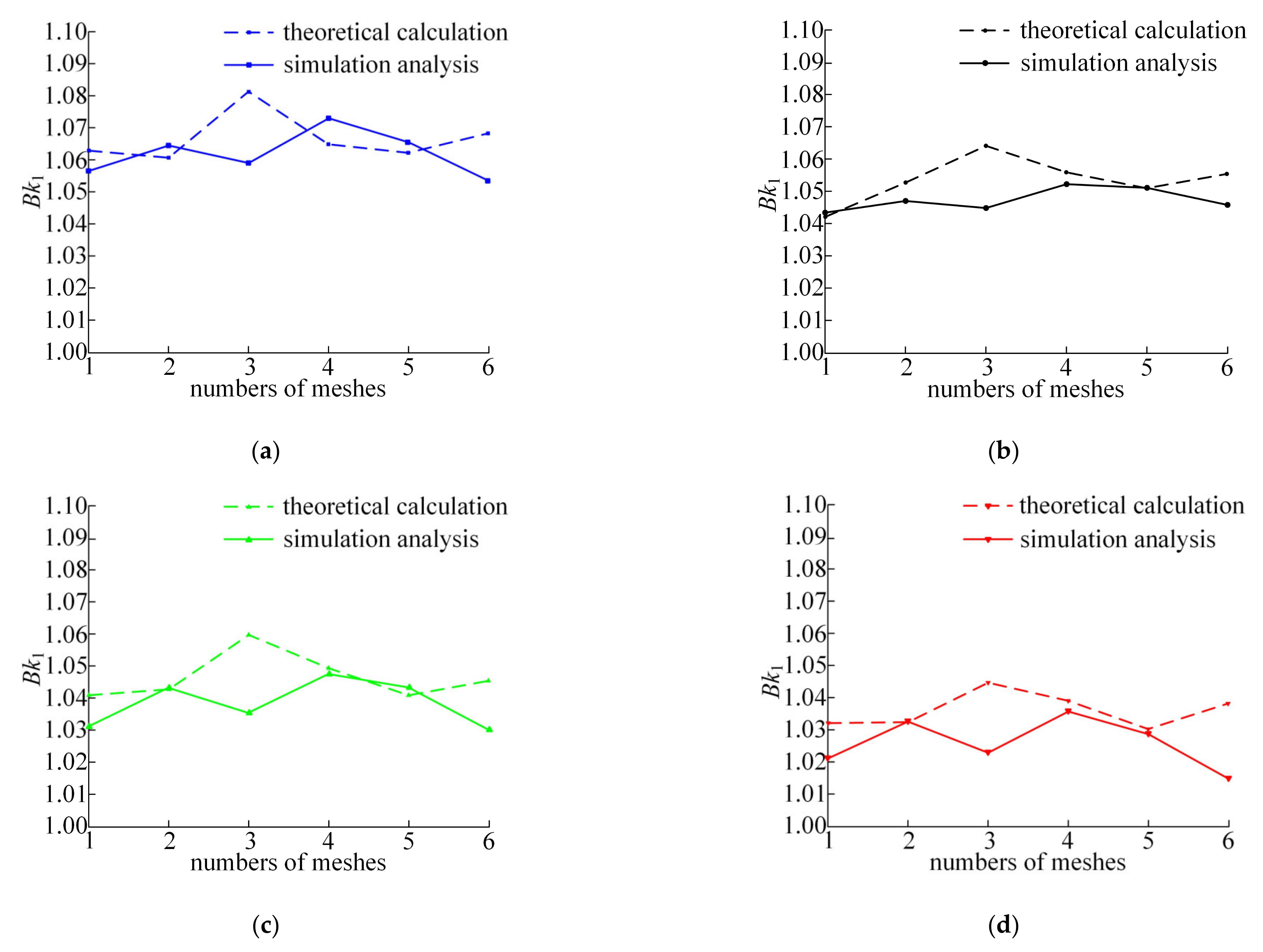
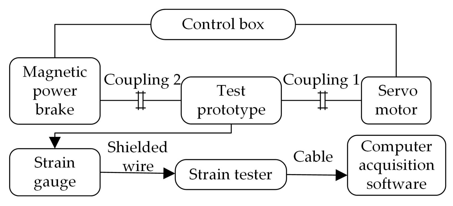
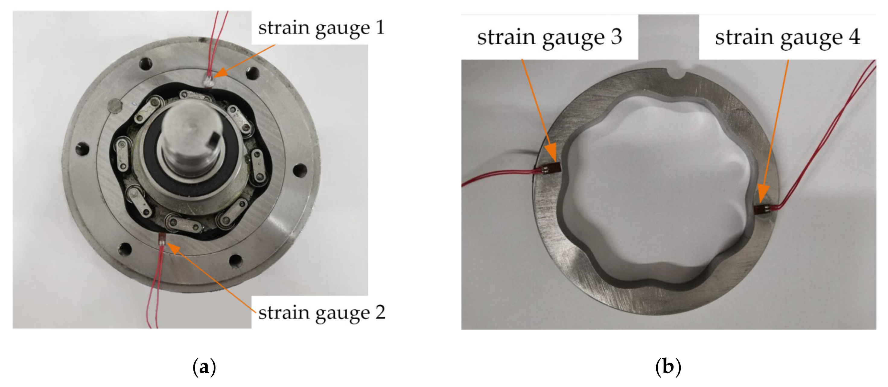
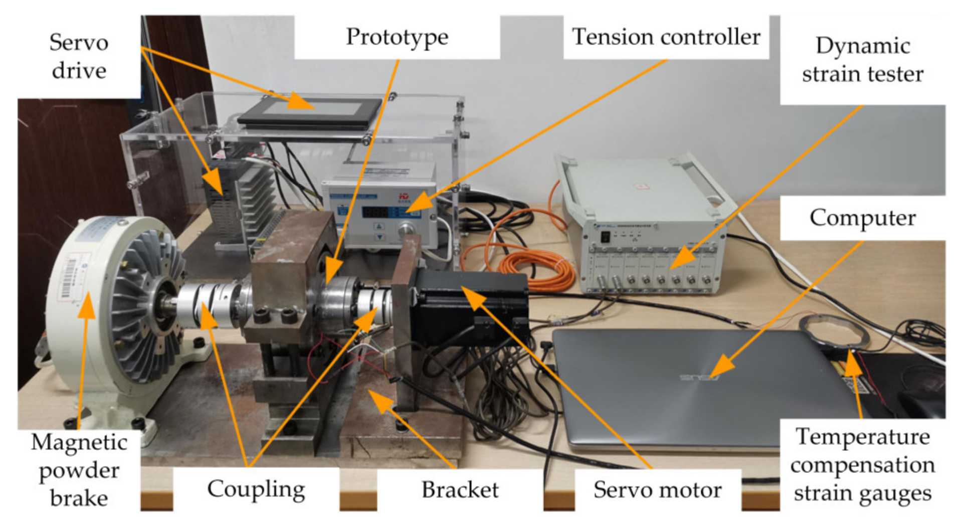
6. Experimental Test and Analysis

In order to verify the influence of the load torque and the input speed on the load inhomogeneity of the two-tooth difference swing-rod movable teeth transmission system, a dynamic load test bench was designed and built to study the distribution uniformity of the system dynamic load under different working conditions. Because the meshing position between the movable teeth and the ring gear changes constantly, it is impossible to measure the dynamic load of the meshing pairs directly. Therefore, in this experiment, the strain generated by dynamic load on the ring gear was measured to complete the study. Then, according to the elastic modulus of the material, the measurement results were transformed into dynamic load between the meshing pairs to study the system load inhomogeneity.
Due to the low power of the prototype to be tested and the need for load conversion during operation, an open power flow mode was used for the test bench. The power required by the system was provided by the servo motor and then transferred to the loading device by the transmission parts, and the remaining energy was consumed by the loading device. The whole power transfer direction forms a closed circuit. Its basic schematic diagram is shown in Figure 11.
The test bench mainly consists of two parts. One is the measurement system, the other one is the dynamic strain testing and analysis system. The measurement system is mainly composed of a drive motor, a control box, a test prototype, a magnetic powder brake, a DHDAS dynamic strain tester, and strain sensors. There are two symmetrical measuring points on the prototype; the corresponding pasted positions of strain gauges are shown in Figure 12a. The strain gauges required for the test were 120 Ω resistance unidirectional strain gauges. We used a half-bridge circuit composed of test strain gauges, temperature compensation strain gauges, and two 120 Ω resistors built in the dynamic strain tester, which can improve the accuracy of the test system. The temperature compensation strain gauges are pasted as shown in Figure 12b.
The dynamic strain testing and analysis system was mainly accomplished via the test software, whose function is to receive, store, and analyze the data signals transmitted by the dynamic strain tester. The overall installation of the strain test system is shown in Figure 13.

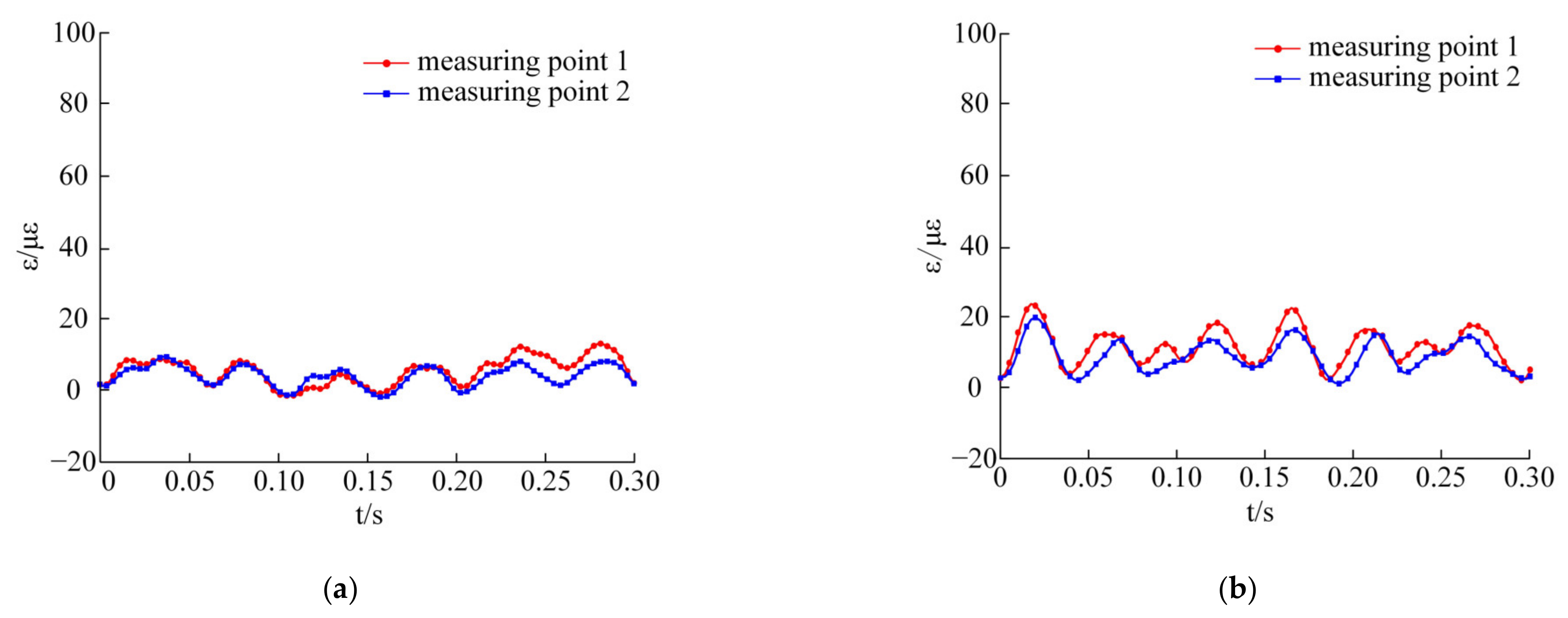
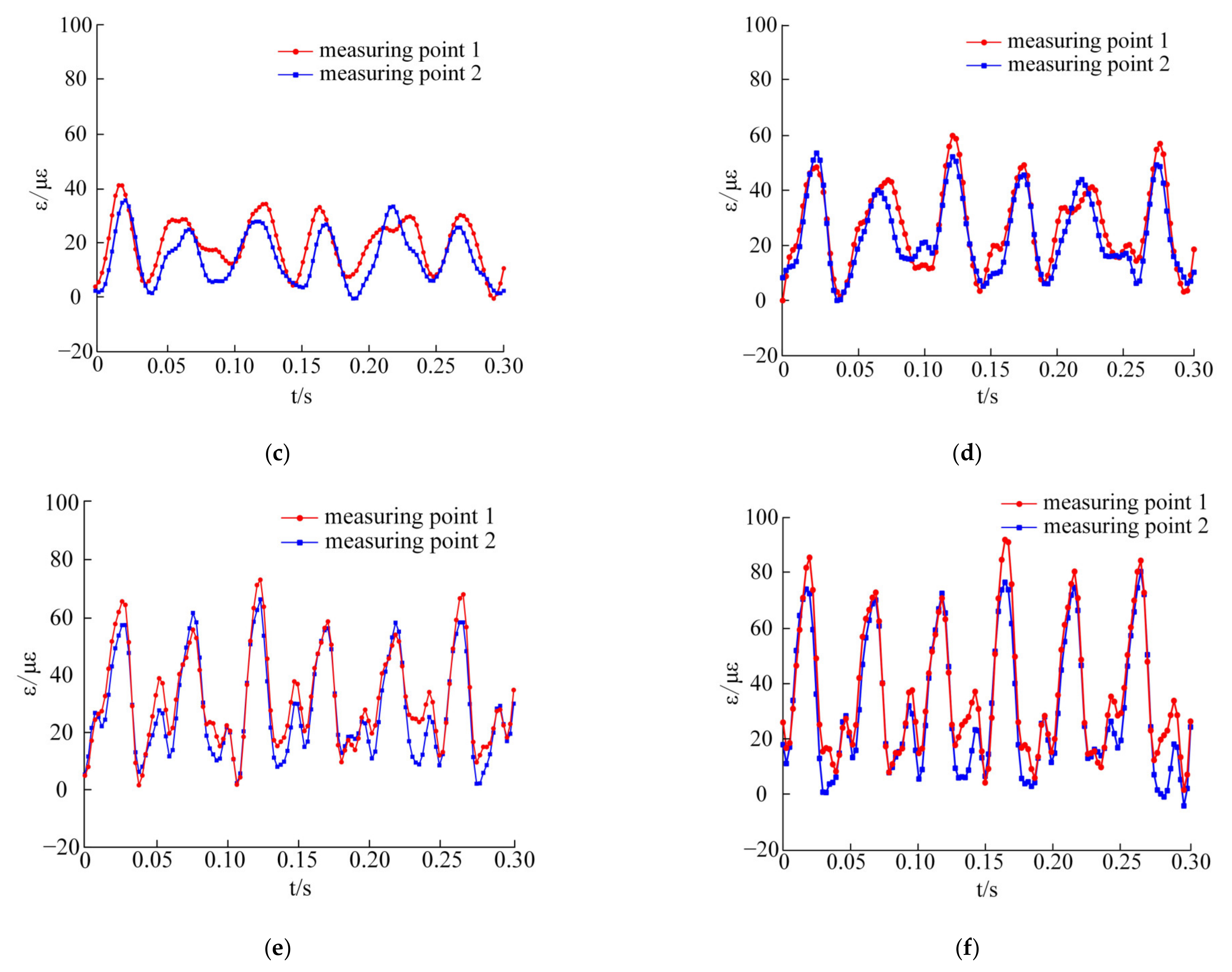
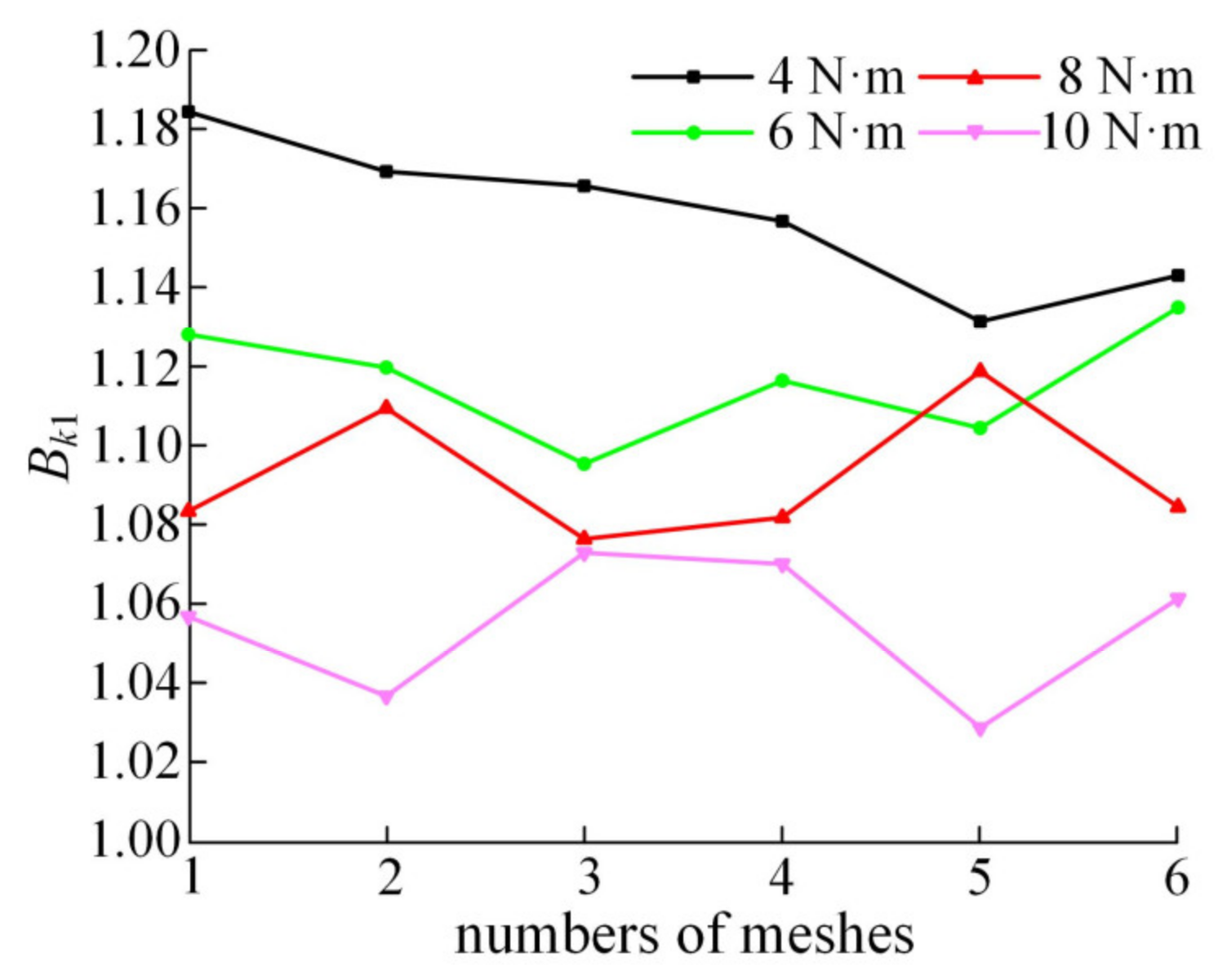
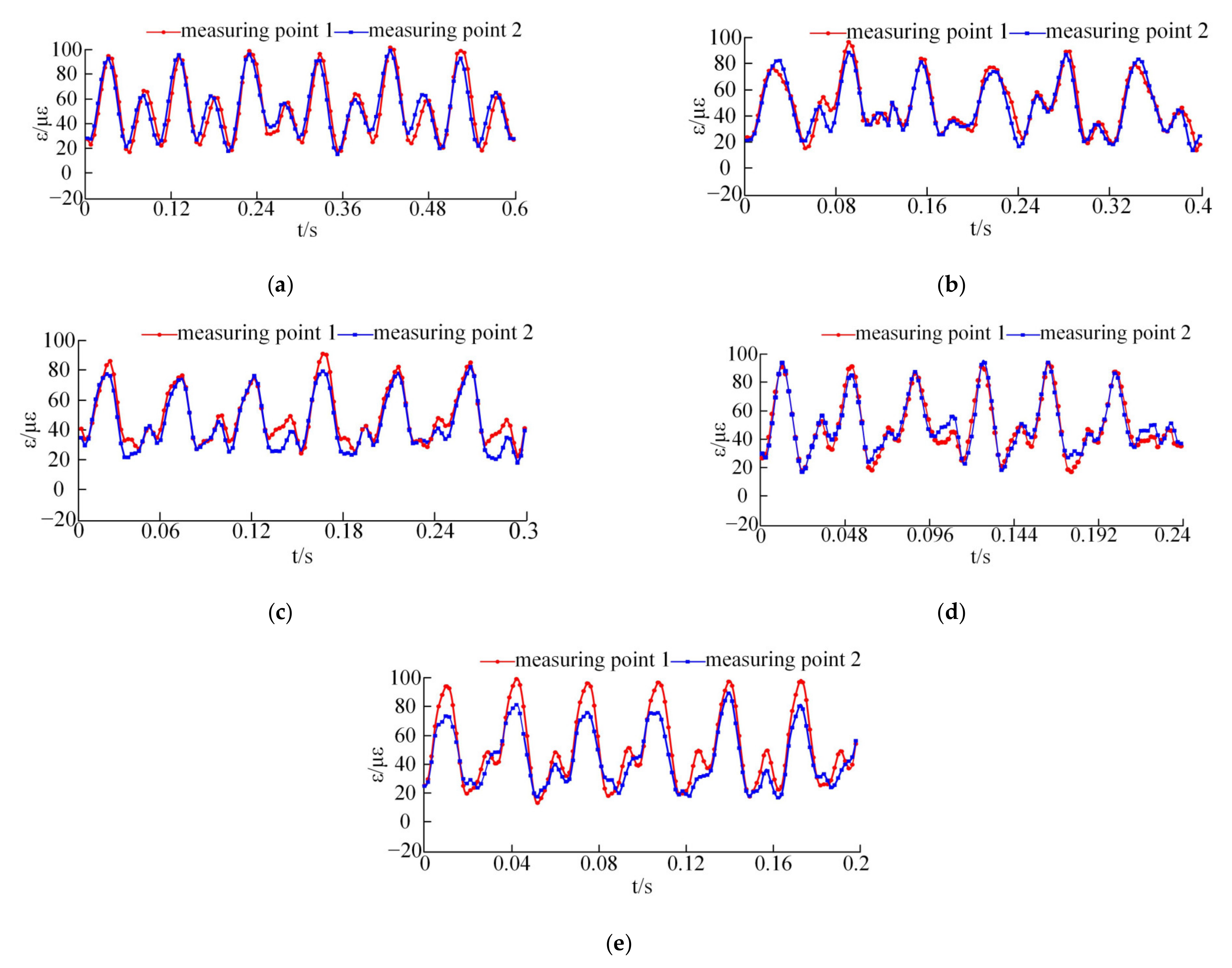
6.1. Influence of Load on Dynamic Load of Meshing Pairs

By controlling the tension controller to change the load torque in the test system, the variation curves of strain values ε are shown in Figure 14. The values ε were measured at two strain measuring points in the direction of center symmetry under different load torques.
There are six peaks and troughs at the measuring points when the separator rotates for one cycle. As the load torque increases, the periodicity becomes more obvious. In Figure 14a, the strain signal detected by the dynamic strain test system under no-load conditions is mainly due to the vibration of the system, the sinusoidal AC signal, and the electromagnetic interference of the servo motor, which causes a zero shift of the strain values ε in the test. Therefore, alternating current should be avoided as much as possible in the strain detection test, and electromagnetic interference to test results should be shielded.
In Figure 14b, when a 2 N·m load is applied to the magnetic powder brake, the amplitude fluctuations of the strain curves are larger than that without load. The maximum strain values detected by the two measuring points are 23.24 με and 19.86 με, respectively. Since the strain value generated after loading is smaller than the strain value of the basic error, the strain value is relatively sensitive to the change of external factors under the load of 2 N·m and is easily influenced by the change of external factors. In order to ensure the accuracy of the test data, the load conditions above 4 N·m were selected for comparative analysis.
As shown in Figure 14c, the maximum strain values of the two measuring points are 40.74 με and 35.34 με. The maximum strain values of the two measuring points in Figure 14d are 60.15 με and 53.82 με. The maximum strain values of the two measuring points in Figure 14e are 74.40 με and 66.70 με. In Figure 14f, the maximum strain values of the two measuring points are 91.08 με and 84.34 με. It can be seen from the comparison that with the increase in load torque, the strain amplitude of the meshing pairs also increases, the interference of external errors on the detection results decreases, and the periodicity of the strain curves becomes more obvious. The strain curves of the two measuring points in the above figures are obviously different, which indicates that the load is not uniform in the system.
As shown in Figure 15, test data with loads above 4 N·m were selected and transformed into dynamic load between the meshing pairs for comparative analysis. Using Equations (10) and (11), the load proportional coefficient curves under different load conditions at the same speed can be obtained.
Figure 15 shows the change curves of the load proportional coefficient under different load conditions. The average values corresponding to each curve are 1.1582, 1.1167, 1.0928, and 1.0550, respectively. Compared with the average values of the load proportional coefficient analyzed in Figure 8, the result is shown in Figure 16.
Figure 16 shows the variation curves of the average value of the load proportional coefficient under different loads obtained from theoretical calculation, simulation analysis, and test measurement. The test measurement results are 3.78–10.5% larger than the theoretical analysis results and 2.93–9.91% larger than the simulation analysis results. The main reason is that only the fixed errors of some components are considered in the theoretical and simulation analysis, while all the errors of the prototype are involved in the experiment. Moreover, the vibration caused by impact load, the fluctuation of input speed, and load torque have not been considered in the theoretical calculation or the simulation analysis. In addition, the effect of external magnetic field and current on the strain system during the test leads to a zero shift of the strain value, resulting in larger overall measurement results. Therefore, there are some numerical differences between the test results and those of the theoretical calculation and the simulation analysis.
In addition, it can be seen from Figure 16 that with the increase in load, the decrease rate of the load proportional coefficient of theoretical calculation and simulation analysis is basically the same and relatively gentle. However, the rate of decrease rate of the load proportional coefficient obtained from the test is obviously greater. This is because in the actual prototype, the transmission components will undergo flexible deformation under the action of load, and the load will cause the redistribution of assembly errors, so as to reduce the impact of initial errors on the load distribution. Therefore, as the load increases, the load proportional coefficient decreases faster in the test than in theoretical calculation or simulation analysis.

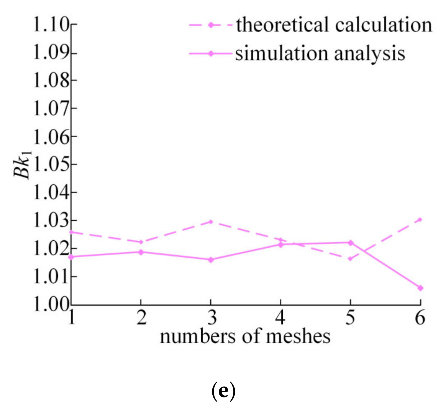
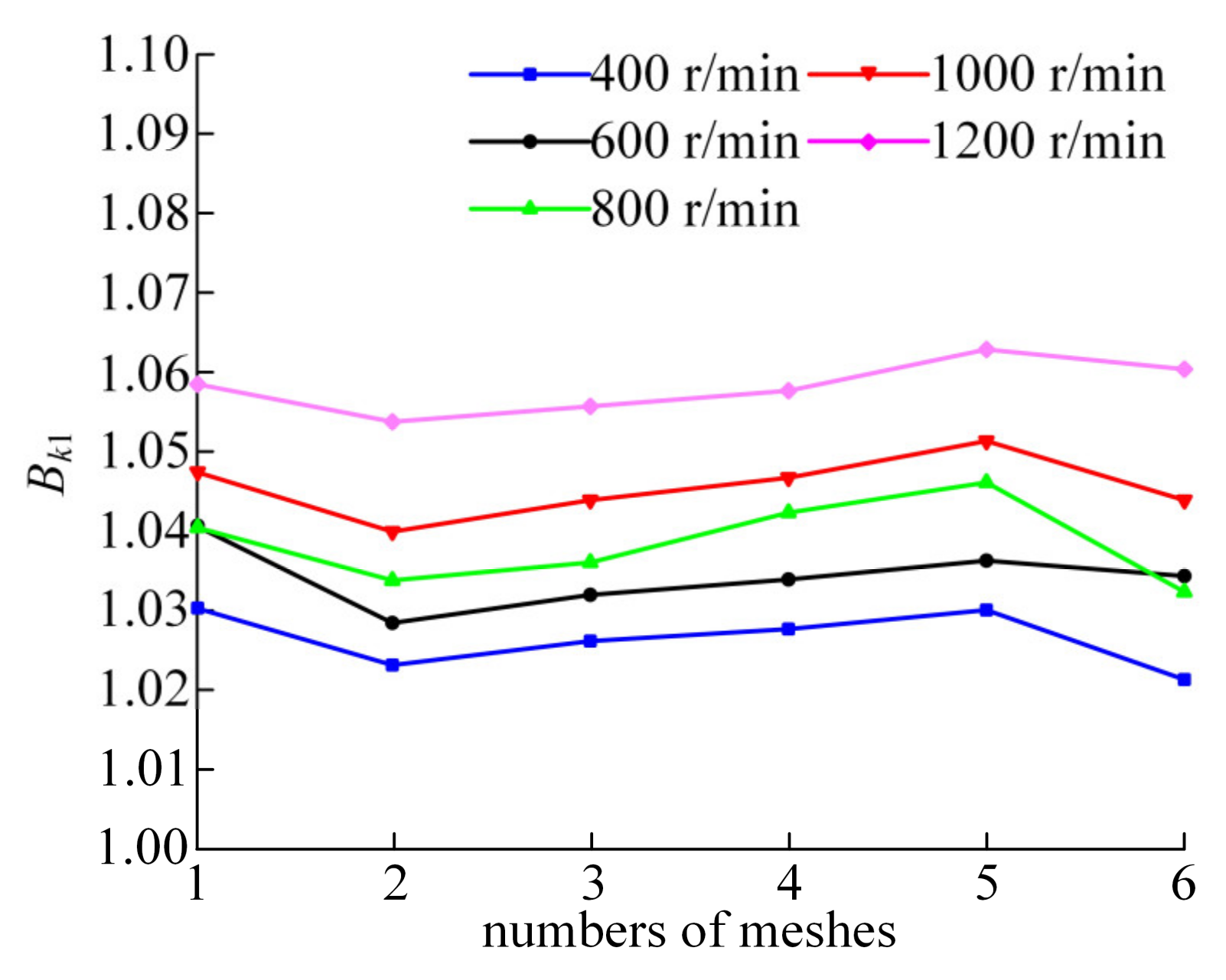
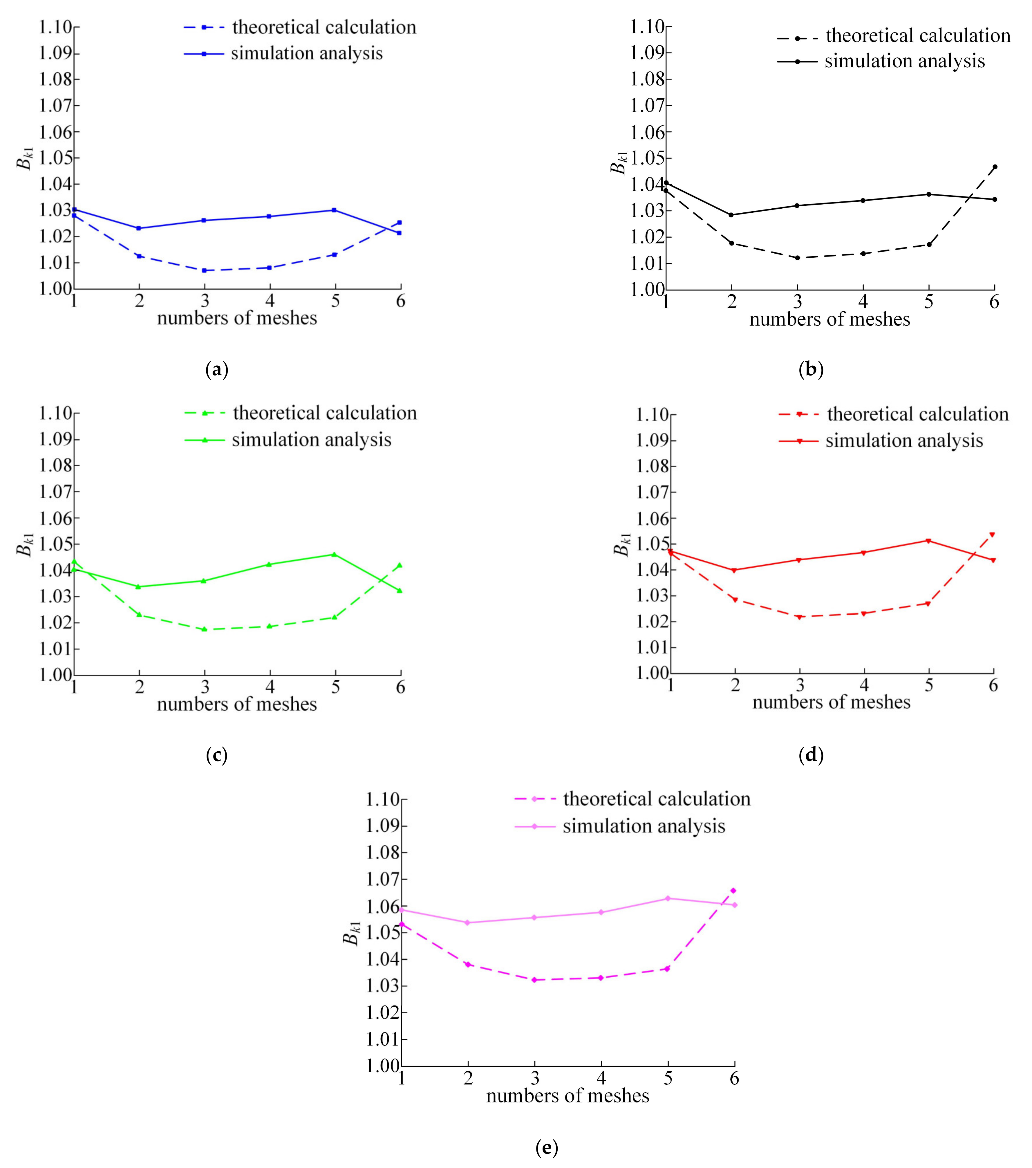
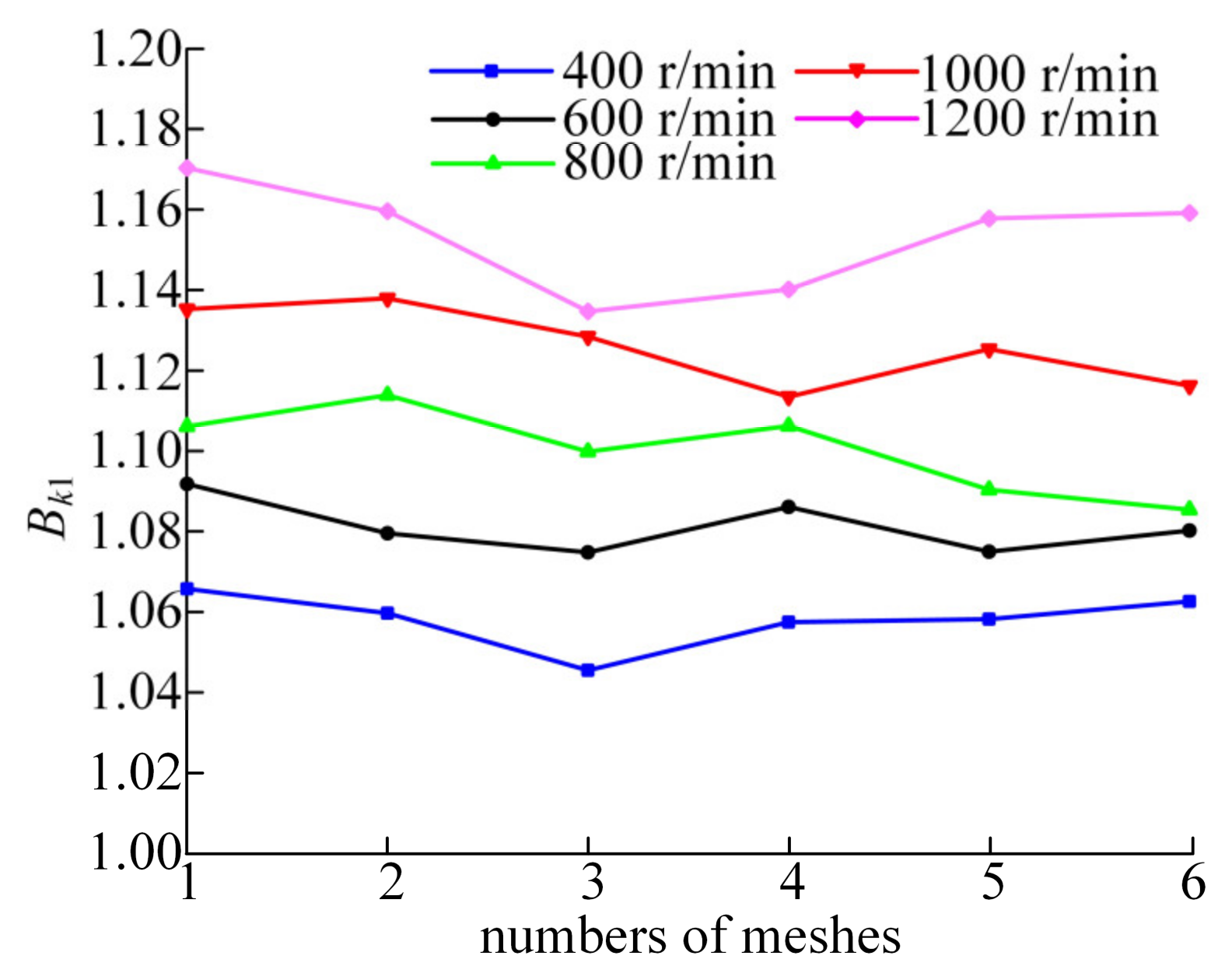
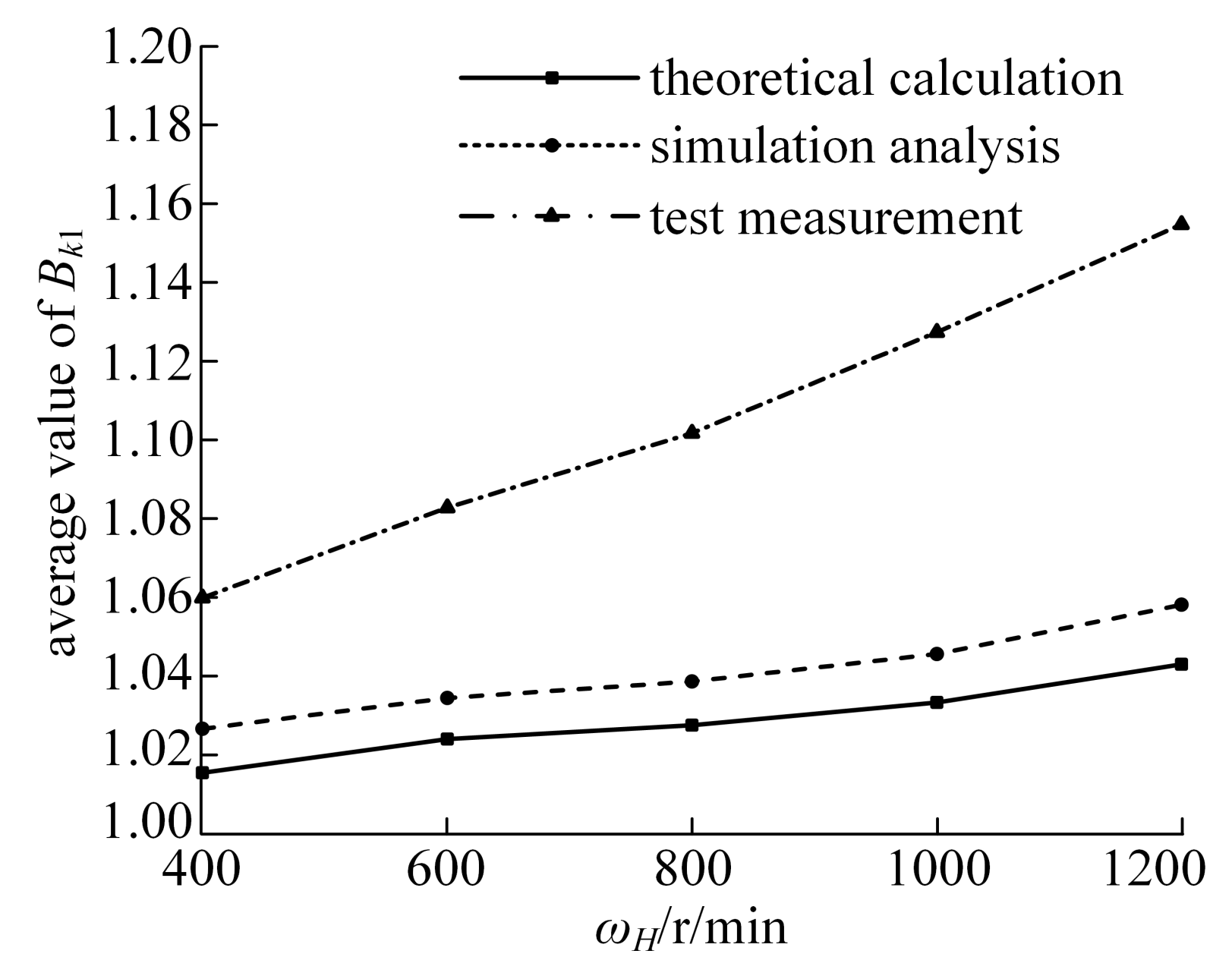
6.2. Influence of Rotational Speed on Dynamic Load of Meshing Pairs

The load torque of the magnetic powder brake was controlled to be 10 N·m, and the motor speed was set to 400 r/min, 600 r/min, 800 r/min, 1000 r/min, and 1200 r/min. The rotation periods of the separator corresponding to these rotation speeds are 0.6 s, 0.4 s, 0.3 s, 0.24 s, and 0.2 s, respectively. As shown in Figure 17, under the load of 10 N·m, the strain curves of the two measuring points in one rotation period of the separator at different speeds were recorded.
It can be seen from the amplitudes that the change of the input speed has little effect on the maximum value of the strain amplitude. However, with the increase in input speed, the difference of strain values measured at the two measuring points becomes obvious.
According to the strain data at different input speeds, the dynamic loads between the corresponding meshing pairs are calculated, and then the load proportion coefficient curves can be obtained, as shown in Figure 18.
According to the load proportion coefficient curves in Figure 18, the average values of Bk1 under different speeds are 1.0602, 1.0831, 1.1019, 1.1276, and 1.1549, respectively. Compared with the average values of the load proportional coefficient analyzed in Figure 10, the variation curves of the load proportional coefficient obtained through theoretical calculation, simulation analysis, and test measurement are shown in Figure 19.
By comparing the values, it can be found that the experimental test results are 4.4–10.7% larger than that of the theoretical analysis and 3.2–9.1% larger than that of the simulation analysis. In addition, it can be seen from Figure 19 that as the input speed increases, the difference between the results obtained by theoretical calculation and those obtained by simulation analysis does not change much, whilst the gap with the experimental results gradually widens. The main reason is that due to the existence of clearance, the system vibration caused by impact load will become more obvious with the increase in input speed. Therefore, although the average value of the load proportional coefficient in theoretical calculation, simulation analysis, and test increases with the increase in input speed, the increase rate of test results is obviously faster.

7. Conclusions

In this study, a lumped parameter dynamic equivalent model of the two-tooth difference swing-rod movable teeth transmission system is established to study the influence of external excitation on load inhomogeneity, and the theoretical analysis method is verified by simulation and experiments. The main conclusions are as follows:
(1)
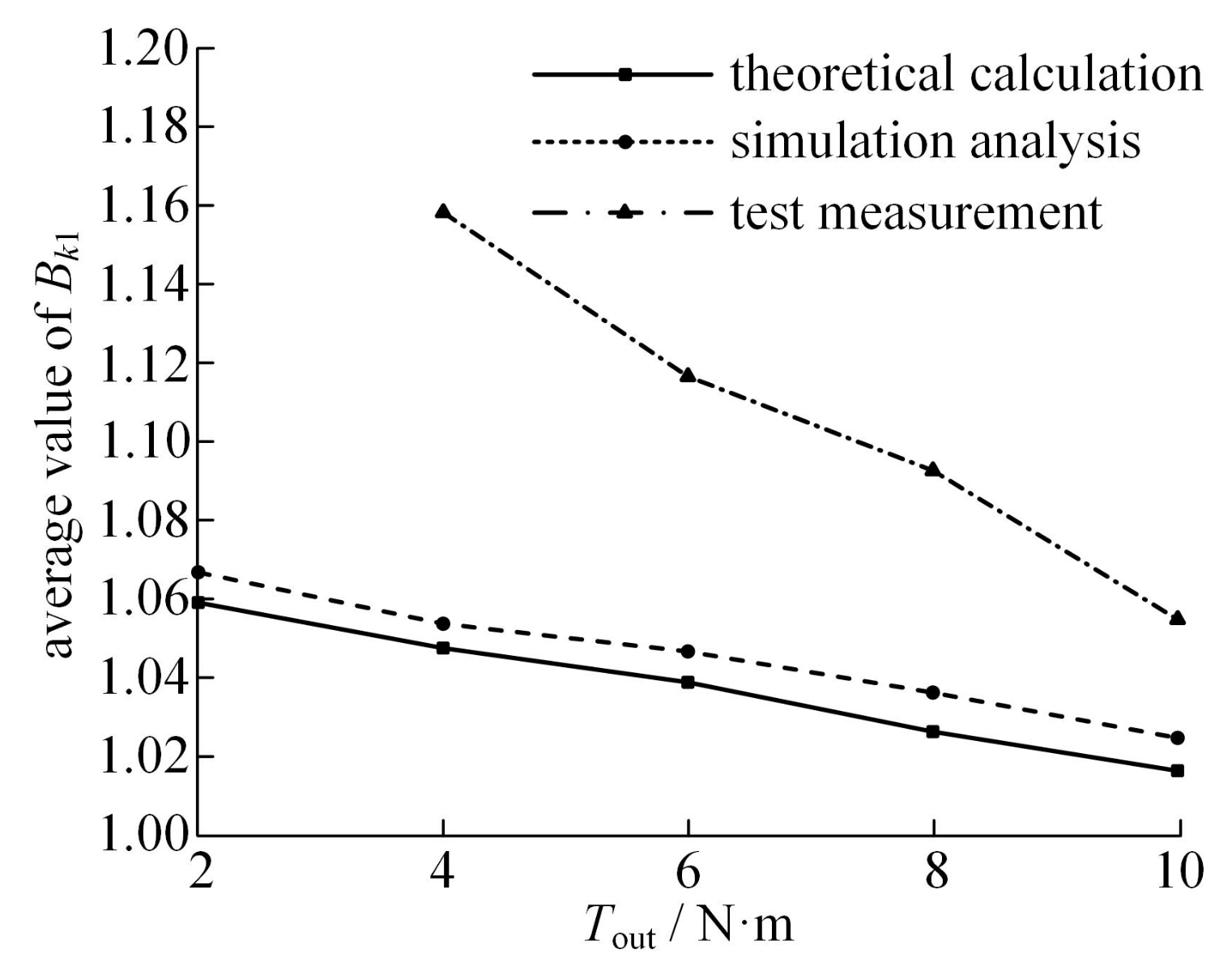
Under different working conditions, the difference rate between the average value of the load proportional coefficients measured by experiment and that obtained by theoretical calculation and simulation analysis is within 10.7%. In addition, the general variation trend of the average value of the load proportional coefficients obtained from theoretical calculation, simulation analysis, and test measurement are consistent, which verifies the correctness of the theoretical model, the virtual prototype model, and the feasibility of the test method.
(2)
The deformation of components can ameliorate the uneven load distribution caused by errors to a certain extent. The increase of the load torque increases the strain amplitude of the meshing pair, thereby reducing the interference of the errors on the uniform distribution of the load, which makes the load distribution more uniform with the increase in load.
(3)
The change in input speed has little effect on the maximum value of the strain amplitude. However, the increase in input speed leads to more obvious load difference between the two movable teeth with center symmetry, which makes the system load non-uniformity more serious. This shows that the load uniformity of the two-tooth difference swing-rod movable teeth transmission system is better when working under low speed conditions.

Author Contributions

Conceptualization, R.W.; data curation, M.W. and M.C.; formal analysis, R.W.; investigation, R.W.; methodology, R.W. and M.W.; resources, H.J.; supervision, Y.Y.; validation, R.W., M.W. and M.C.; writing—original draft, R.W.; writing—review and editing, Y.Y. and H.J. All authors have read and agreed to the published version of the manuscript.

Funding

This work was supported by the National Natural Science Foundation of China (Grant No. 51605416).

Institutional Review Board Statement

Not applicable.

Informed Consent Statement

Not applicable.

Data Availability Statement

Not applicable.

Conflicts of Interest

The authors declare no conflict of interest.

Nomenclature

NotationUnitDescription
kpN/mthe support stiffness of the part p; p = h, g, k
cpN·s/mthe support damping of the part p; p = h, g, k
kptN/mthe torsional stiffness of the part p; p = h, g, k
cptN·s/mthe torsional damping of the part p; p = h, g, k
kipN/mthe meshing stiffness between the ith movable tooth and the part p; p = h, g, k
cipN·s/mthe meshing damping between the ith movable tooth and the part p; p = h, g, k
xpmthe transverse displacement of the part p; p = h, g, k
ypmthe longitudinal displacement of the part p; p = h, g, k
upmThe torsional displacement of the part p; p = h, g, k
ximthe transverse displacement of the ith movable tooth
yimthe longitudinal displacement of the ith movable tooth
uimthe torsional displacement of the ith movable tooth
bhmThe support clearance of the wave generator
bihmhalf of the meshing gap between the ith movable tooth and the wave generator
bikmhalf of the meshing gap between the ith movable tooth and the ring gear
M the meshing point of the ith movable tooth and the ring gear
N the meshing point of the ith movable tooth and the wave generator
β i h radthe angle between the normal line at the meshing point N relative to the fixed horizontal axis XK
β i k radthe angle between the normal line at the meshing point M relative to the fixed horizontal axis XK
α radthe angle between the horizontal axis XK and the line connecting the coordinate origin O and the movable tooth center O2
φ radthe angle between the length direction of the swing rod and the line connecting the coordinate origin O and the swing rod rotation center O1
ξ radthe angle between the length direction of the swing rod and the line connecting the movable tooth center O2 and the coordinate origin O
Δihmthe relative displacement of the wave generator to the ith movable tooth in the normal direction of their meshing point N
Δikmthe relative displacement of the ring gear to the ith movable tooth in the normal direction of their meshing point M
Δigmthe relative displacement of the separator to the ith movable tooth in the length direction of the swing rod
eihmthe equivalent error of the ith movable tooth meshing with the wave generator
eikmthe equivalent error of the ith movable tooth meshing with the ring gear
mpkgthe mass of the part p; p = h, g, k
Ipkg·m2the moment of inertia of the part p; p = h, g, k
rpmthe equivalent radius of the part p; p = h, g, k
TinN·mthe input torque of the wave generator
ToutN·mthe output torque of the separator
mikgthe mass of the ith movable tooth
Iikg·m2the moment of inertia of the ith movable tooth
rimthe equivalent radius of the ith movable tooth
FkiNthe dynamic load between the ith movable tooth and the ring gear
Ω k i j the load proportional coefficient when the ith movable tooth meshes with the ring gear
Bki the load proportional coefficient of the ith movable tooth with the ring gear in the meshing period
ω H r/minthe input speed of the wave generator
ω G r/minthe output speed of the separator

References

  1. Wang, Y.F.; Zhang, Q.P. Study on Virtual Prototype Modeling of Swing Movable Teeth Transmission. Appl. Mech. Mater. 2014, 607, 325–328. [Google Scholar] [CrossRef]
  2. Qu, J.F. Mechanism Innovation Principle; Science Press: Beijing, China, 2001; pp. 1–20. [Google Scholar]
  3. Qin, B.; Yin, H.; Wang, Z.; Zhang, J.Q.; Li, Z.J.; Wang, J.G. Application of EMPE and KP-KELM in Fault Diagnosis of Planetary Gearbox. J. Mech. Transm. 2019, 43, 146–151. [Google Scholar]
  4. Dong, X.R.; Li, J.F.; Wang, X.H.; Liu, Z.F. Structural and Tooth Profile Analysis on Cam Profile Compound Teeth Transmission. China Mech. Eng. 2006, 16, 1661–1665. [Google Scholar]
  5. Wei, R.; Jin, H.R.; Yi, Y.L. Research on the transmission error of swing-rod movable teeth transmission system. Mech. Ind. 2020, 21, 409. [Google Scholar] [CrossRef]
  6. Liang, S.M.; Zhang, J.F.; Xu, L.J. Study on elasto-dynamic model of swing movable teeth transmission system. J. Mech. Eng. 2002, 38, 142–146. [Google Scholar] [CrossRef]
  7. Yang, R.G.; An, Z.J.; Duan, L.Y. Analysis of Free Vibration of Cycloid Ball Planetary Transmission. China Mech. Eng. 2016, 27, 1883–1891. [Google Scholar]
  8. Yi, Y.L.; Gao, Y.F.; He, L.; Jin, H.R. Thermoelastic stress-strain analysis of the meshing pairs of a two-tooth difference swing-rod movable toothed drive. Strength Mater. 2019, 51, 633–645. [Google Scholar] [CrossRef]
  9. Xu, L.Z.; Wang, W.P. Quasi-static analysis of forces and stress for a novel two-step movable tooth drive. Mech. Des. Struct. Mach. 2018, 46, 285–295. [Google Scholar] [CrossRef]
  10. Dong, J.X.; Wang, Q.B.; Tang, J.Y.; Hu, Z.H.; Li, X.Q. Dynamic characteristics and load-sharing performance of concentric face gear split-torque transmission systems with time-varying mesh stiffness, flexible supports and deformable shafts. Meccanica 2021, 56, 2893–2918. [Google Scholar] [CrossRef]
  11. Dong, H.; Zhang, H.Q.; Zhao, X.L.; Duan, L.L. Study on the load-sharing characteristics of face-gear four-branching split-torque transmission system. Adv. Mech. Eng. 2021, 13, 1–15. [Google Scholar]
  12. Mo, S.; Yue, Z.X.; Feng, Z.Y.; Gao, H.J. Analytical investigation on load sharing characteristics for face gear split flow system. J. Huazhong Univ. Sci. Technol. 2020, 48, 23–28. [Google Scholar] [CrossRef]
  13. Hu, S.Y.; Fang, Z.D.; Xu, Y.Q.; Guan, Y.B.; Shen, R. Meshing impact analysis of planetary transmission system considering the influence of multiple errors and its effect on the load sharing and dynamic load factor characteristics of the system. J. Multi-Body Dyn. 2021, 235, 57–74. [Google Scholar] [CrossRef]
  14. Xu, X.Y.; Yang, W.; Diao, P.; Tao, Y.C. Research of the Dynamic Load Sharing of Heavy Load Planetary Gear System with Multi-floating Component. J. Mech. Transm. 2016, 40, 6–11. [Google Scholar]
  15. Zhang, H.B.; Wu, S.J.; Peng, Z.M. A nonlinear dynamic model for analysis of the combined influences of nonlinear internal excitations on the load sharing behavior of a compound planetary gear set. J. Mech. Eng. Sci. 2016, 230, 1048–1068. [Google Scholar] [CrossRef]
  16. Zhang, H.B.; Shen, X.F. A dynamic tooth wear prediction model for reflecting “two-sides” coupling relation between tooth wear accumulation and load sharing behavior in compound planetary gear set. J. Mech. Eng. Sci. 2020, 234, 1746–1763. [Google Scholar] [CrossRef]
  17. Bodas, A.; Kahraman, A. Influence of Carrier and Gear Manufacturing Errors on the Static Load Sharing Behavior of Planetary Gear Sets. JSME Int. J. Ser. C 2004, 47, 908–915. [Google Scholar] [CrossRef] [Green Version]
  18. Sanchez-Espiga, J.; Fernandez-del-Rincon, A.; Iglesias, M.; Viadero, F. Planetary gear transmissions load sharing measurement from tooth root strains: Numerical evaluation of mesh phasing influence. Mech. Mach. Theory 2021, 163, 104370. [Google Scholar] [CrossRef]
  19. Sun, W.; Li, X.; Wei, J.; Zhang, A.Q.; Ding, X.; Hu, X.L. A study on load-sharing structure of multi-stage planetary transmission system. J. Mech. Sci. Technol. 2015, 29, 1501–1511. [Google Scholar] [CrossRef]
  20. Wang, Y.F.; Yang, B. Study on Dynamic Simulation of Swing Movable Teeth Reducer. Appl. Mech. Mater. 2014, 496–500, 749–753. [Google Scholar] [CrossRef]
  21. Yi, Y.L.; Guo, H.; Wei, R.; Jin, H.R. Transmission error analysis of swing-rod movable teeth drive based on functionary line increment means. Manuf. Technol. Mach. Tool 2018, 8, 64–70. [Google Scholar]
  22. Yi, Y.L.; Dou, L.R.; Guo, H.; Jin, H.R. Coupling Stiffness of Double Outer Generator Swing Rod Movable Teeth Transmission. China Mech. Eng. 2018, 29, 644–649. [Google Scholar]
Figure 1. The two-tooth difference swing-rod movable teeth transmission system.
Machines 10 00502 g001
Figure 2. Dynamic equivalent calculation model of the two-tooth difference swing-rod movable teeth transmission system.
Machines 10 00502 g002
Figure 3. Relative displacement relation of components.
Machines 10 00502 g003
Figure 4. The variation curves of the load proportional coefficient under different load torques.
Machines 10 00502 g004
Figure 5. The variation curves of the load proportional coefficient under different input speeds.
Machines 10 00502 g005
Figure 6. Virtual prototype simulation model.
Machines 10 00502 g006
Figure 7. Load proportional coefficient curves under different load torques.
Machines 10 00502 g007
Figure 8. Comparison of load proportional coefficient curves under different loads: (a) 2 N·m; (b) 4 N·m; (c) 6 N·m; (d) 8 N·m; (e) 10 N·m.
Machines 10 00502 g008aMachines 10 00502 g008b
Figure 9. Load proportional coefficient curves under different input speeds.
Machines 10 00502 g009
Figure 10. Comparison of load proportional coefficient curves at different input speeds: (a) 400 r/min; (b) 600 r/min; (c) 800 r/min; (d) 1000 r/min; (e) 1200 r/min.
Machines 10 00502 g010
Figure 11. Basic schematic diagram of test bench.
Machines 10 00502 g011
Figure 12. Strain gauges for test: (a) Ring gear pasted strain gauges; (b) Temperature compensated strain gauges.
Machines 10 00502 g012
Figure 13. Figure of the overall installation of strain test system.
Machines 10 00502 g013
Figure 14. Strain curves under different loads: (a) Strain curves without load; (b) 2 N·m; (c) 4 N·m; (d) 6 N·m; (e) 8 N·m; (f) 10 N·m.
Machines 10 00502 g014aMachines 10 00502 g014b
Figure 15. Load proportional coefficient curves under different loads.
Machines 10 00502 g015
Figure 16. Variation curves of the average value of Bk1 under different loads.
Machines 10 00502 g016
Figure 17. Strain curves under different input speeds: (a) 400 r/min; (b) 600 r/min; (c) 800 r/min; (d) 1000 r/min; (e) 1200 r/min.
Machines 10 00502 g017
Figure 18. Load proportion coefficient curves under different speeds.
Machines 10 00502 g018
Figure 19. Variation curves of the average value of BK1 under different speeds.
Machines 10 00502 g019
Table 1. Basic parameters of the transmission system.
Name of ComponentNumber of TeethQuality (kg)Moment of Inertia (kg·m2)
H (wave generator)20.42588.525 × 10−5
K (ring gear)60.18323.868 × 10−4
G (separator) 0.98714.420 × 10−4
movable tooth80.01031.193 × 10−5
Table 2. Constraints of each component.
PartsReferenceConstraint Type
ring gearthe earthfixed pair
wave generatorthe earthrevolute pair
separatorthe earthrevolute pair
swing rodseparatorrevolute pair
movable toothswing rodfixed pair
movable toothwave generatorcontact pair
movable toothring gearcontact pair
Table 3. Average value comparison of load proportional coefficient under different loads.
LoadTheoretical Calculation ValueSimulation ValueError (%)
2 N∙m1.05921.06690.7
4 N∙m1.04771.05380.6
6 N∙m1.0391.04680.8
8 N∙m1.02651.03641.0
10 N∙m1.01661.02490.8
Table 4. Average value comparison of load proportional coefficient under different input speeds.
Input SpeedTheoretical Calculation ValueSimulation ValueError (%)
400 r/min1.01591.0271.1
600 r/min1.02441.03481.0
800 r/min1.02791.03891.1
1000 r/min1.03371.0461.2
1200 r/min1.04331.05851.5
Publisher’s Note: MDPI stays neutral with regard to jurisdictional claims in published maps and institutional affiliations.

