Article

Sensitivity Analysis for Multi-Objective Optimization of Switched Reluctance Motors

by
Ekaterina Andriushchenko
1,*,
Ants Kallaste
1,
Mohammad Hossain Mohammadi
2,
David A. Lowther
2 and
Hamidreza Heidari
1
1
Department of Electrical Power Engineering and Mechatronics, Tallinn University of Technology, Ehitajate tee 5, 12616 Tallinn, Estonia
2
Department of Electrical and Computer Engineering, McGill University, Montréal, QC H3A 0G4, Canada
*
Author to whom correspondence should be addressed.
Submission received: 5 June 2022 / Revised: 25 June 2022 / Accepted: 8 July 2022 / Published: 11 July 2022

Abstract

:
The main issue of the switched reluctance motor (SRM) is its noise and vibration caused by high torque ripples on the rotor’s shaft. Many methods have been developed for improving the torque characteristic of the SRM. For example, design optimization is one of the promising approaches to the noise and vibration reduction of the SRM. Particularly, topology optimization (TO) of the stator and rotor can be highly beneficial to addressing the torque ripple issue. However, the TO of the SRM appears to be computationally demanding. To overcome this issue, this study proposes a method aiming to reduce the computational complexity of the TO through the reduction of the design space. Particularly, this paper presents a sensitivity analysis of a list of unique design parameters of the SRM and their influence on the average torque of the motor and the torque ripple of the motor. By applying the sensitivity analysis, the design space of the TO could be reduced, leading to a considerable decrease in the TO computational burden. Additionally, valuable conclusions on the geometrical parameters’ influences on the SRM torque and torque ripple have been drawn.

1. Introduction

Recently, there has been increasing interest in switched reluctance motors (SRMs) due to the benefits they provide. Within the SRMs’ structure, no permanent magnets or rotor windings are used. For this reason, the SRMs are highly suitable for high-speed and high-temperature applications. However, the performance of the SRMs is limited by high torque ripple and consequent vibration and noise [1,2].
Previous research has established that the design of the SRM plays an important role in addressing the issue of the torque ripple [3,4,5]. Many studies on SRM have utilized various design optimization techniques to achieve high and stable torque characteristics. Several authors have investigated the possibilities of rotor pole modifications to reduce the torque ripples [6,7,8,9,10]. Another group of studies presents the optimization of classic linear and angular dimensions of the motor [11,12]. The majority of the methods propose simple yet effective modifications of the rotor and stator, aiming to reduce the fringing flux effect and avoid the oversaturation of the pole’s tips. Nevertheless, a wider search for more beneficial shapes is possible with topology optimization (TO).
Nowadays, TO has been shown as a feasible approach for electric motor improvement. Many researchers have successfully obtained advantageous shapes of the motors, enhancing their performance characteristics [13,14]. In this sense, SRMs are not an exception. A considerable improvement in the torque and reduction of the torque ripple of the SRMs have been achieved using TO techniques [15,16]. Yet, a key challenge of the TO application is its high computational complexity. This is especially critical if a finite element model is utilized to calculate the objective function. For instance, the application of the ON/OFF topology optimization method requires a high-density discretization of the motor geometry. The discretization of the motor geometry defines the number of optimization parameters. To carry out TO for the SRM considering all the core body, around 1500 discrete parameters should be involved. This leads to a high number of calculations being needed to analyze the influences of these parameters on the objective function [17].
To overcome the issue of the high computational complexity of the TO, many methods have been developed by researchers in the fields of electromagnetic calculations and motor design. The first group of researchers attempts to replace a FE model of the electrical machine with a surrogate model [18]. The surrogate model represents the motor FE model with high precision but requires the application of complex and computationally demanding methods. Another group of researchers defined crucial areas of the motor geometry based on the fringing flux behavior [13]. Yet, the defined crucial areas are mainly defined approximately and can lead to an improper design space definition.
This paper proposes a method that helps to minimize the design space of the SRM TO using sensitivity analysis (SA). The method involved the definition of the potentially crucial geometrical parameters of the SRM based on a literature review. Then, the SA was applied to determine which parameters have a major impact on the average torque and torque ripple of the motor. Lastly, based on the results of the SA, an optimal and minimal design space of the motor was defined to be utilized within the TO. The SA was accomplished using the Taguchi method. For many years this method has been applied for different purposes, from sensitivity analysis and robust optimization to the design of experiments. It has been recalled by many scientists as a relatively simple, fast, and reliable approach to the SA for motor design problem.
The proposed approach helps to efficiently reduce the design domain of the TO, and consequently decrease the computational complexity of the TO. This allows the speeding up of the overall SRM development and optimization process. To the authors’ knowledge, there have been no studies focused on the TO design domain definition using the Taguchi method. Additionally, this study provides a comprehensive overview of the SRM’s geometric parameters and their influences on the average torque and torque ripple.
The paper is organized as follows. First, the structure and operation principle of the motor are discussed in Section 2. Then, Section 2 gives insights into the torque ripple origins and considers the SRM’s geometrical parameters. Section 3 is dedicated to the design model definition and Taguchi method’s theory with its application. The following chapter concentrates on the results of the SA and the selection of the optimal design space of the TO. Lastly, Section 5 concludes and discusses the research work.

2. Switched Reluctance Motor

2.1. SRM Working Principle

This section briefly introduces the basics of the SRMs which are essential for the average torque and torque ripple improvement. The basic structure, operation principle, electromagnetic characteristics, and control are covered in the following paragraphs.
SRMs have been widely applied for electric propulsion, fan, pump, and servo applications. They possess a simple, robust structure without windings on the rotor, which makes them beneficial for high-speed and high-temperature applications.
There is a list of SRM structures that are primarily defined by the number of stator phases. In this paper, a three-phase 6-stator-pole and 4-rotor-pole SRM is considered. A simplified structure of the motor is presented in Figure 1. As can be seen in the figure, the stator carries the windings of three phases (A, B, and C) and the rotor has a simple 4-pole or 4-tooth structure.
The working principle of the motor is based on the rule of minimum reluctance. This rule is closely connected to the term “phase reluctance” or the opposite of it—“phase inductance.” During the motor operation phase, inductances are constantly changing depending on the effective airgap length between the rotor and stator poles as a function of the rotor position. The operation principle of the SRM is presented in Figure 2, where red is dedicated to the energized phase C, green the energized phase B, and blue the energized phase A. Additionally, Figure 3 gives a detailed representation of the ideal phase inductance variation in relation to the rotor position. The involved stator and rotor teeth are marked with red. As can be seen, the phase inductance is minimum when the rotor teeth are not aligned with the considered stator teeth. When the considered phase is excited, the rotor teeth try to align themselves with the stator teeth to decrease the reluctance (increase the inductance) by reducing the effective air gap length. When the teeth of the stator and rotor are aligned, the phase inductance appears at its maximum. To ensure continuous rotation and operation of the motor, one phase gets turned on after other switches off. Prior to the area of maximum inductance, the phase voltage switches of and the current falls to zero. If the voltage continues to be supplied to the considered phase, a negative torque will be produced.
As shown in Figure 3, the DC-voltage is supplied to a phase at the rotor position when the inductance is at its growing phase. To illustrate this process mathematically, the following equation can be considered.
T θ , i = 0 i L θ , i θ i d i .
where T is the produced phase torque, θ denotes the rotor position angle, and i is the phase current.
To maintain continuous torque production, the control scheme of a three-phase 6/4-pole SR motor drive is applied (see Figure 4). Usually, the SRM is run by an asymmetric bridge converter, where each phase is controlled independently. A switching pattern directs the DC voltage to one of the phases depending on the rotor’s position. For this purpose, the SRM drive often comprises six position-controlled and current-controlled switches.
Traditionally, the commutation pattern of the SRM motor is defined based on the static representation of the phase inductance profile. Assuming the symmetricity of the stator and rotor poles, the classic commutation pattern for the 6/4 pole SRM can be illustrated by Figure 5. It is important to highlight that a phase winding should be excited during of the phase inductance growth. Therefore, the duration of the phase voltage application is 30° of the mechanical position of the motor.

2.2. Torque Ripple

A main challenge of the SRM drive is high levels of vibration and noise during operation. It has been revealed that the key reasons for the SRM’s vibrations are the unstable, fluctuating torque at the motor shaft. Numerous studies have proved that the SRM’s torque ripples are mainly caused by the fringing flux which appears just before the rotor and stator teeth overlap, as shown in Figure 6. The consequence of the fringing flux is the nonlinear growth of the phase inductance profile, which triggers the torque also to grow nonlinearly. The nonlinearly of the magnetic torque negatively influences the phase current and leads to unstable torque production. Figure 7 illustrates the described process graphically.
There are various methods in the literature that address the torque ripple issue from different points of view. The most well-known approaches are motor design modification and control algorithm adjustment. It has been shown that particular geometries of the rotor and stator poles reduce the fringing flux, improve the inductance profile, and consequently, suppress the torque ripples. These geometries are considered in the following section.

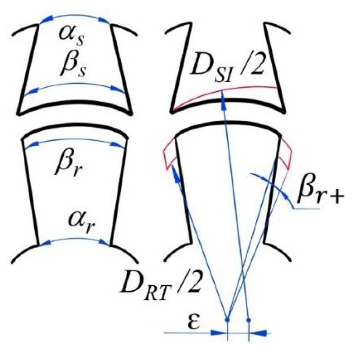
2.3. Geometrical Parameters of SRM

This section describes in detail the crucial geometrical parameters of the SRM which are illustrated in Figure 8. In the figure, DRT is the diameter of the rotor additional teeth and DSI is the stator inner diameter.
The phase inductance profile of the SRM is highly dependent on the geometry of the rotor, stator, and the airgap—particularly, on the rotor and stator pole angles, β r ,   β s . The duration of the minimum inductance θmin, the duration of the maximum inductance θmax, and the duration of the growing θinc and falling inductance θdec phases can be defined as follows.
θ m i n = α β s + β r / 2 θ m a x = β r β s θ i n c = θ d e c = β s .
where α = 2 π / N r is a rotor pole pitch and N r is the number of the rotor poles.
The stator and rotor pole angles at the core ( α s , α r , respectively) have an indirect influence on the torque ripple minimization. It has been shown by many studies that the variation of α s and α r creates beneficial sharp angles at the beginning of stator and rotor teeth overlap, avoiding the fringing flux appearance [10] and reducing the torque ripple.
The additional tooth angle β r + proposes a similar solution to α s and α r . The additional tooth angle makes a big difference in terms of the wider distributed magnetic flux saturation. Moreover, this parameter addresses torque fall during the excitation transition.
One of the key design parameters influencing the inductance profile is the air-gap shape between the rotor and stator poles. As illustrated in Figure 8, air-gap shift ε helps achieving a variable air-gap length (Lag) with a bigger value at the beginning of the overlap and a smaller value at the end of the overlap. Applying an appropriate value of the air-gap shift allows one to obtain the torque, which grows together with the teeth overlap.
In this sensitivity analysis, the vector of the design parameters is defined as follows:
x = β s , α s , β r , α r , ε , β r +
To avoid unfeasible designs, geometrical constraints are set for the entire space, denoted by F Δ .
F Δ = 25 ° β s 40 ° β s 5 ° α s β s 15 ° 25 ° β r 40 ° β r + 25 ° α r β r + 50 ° 0   mm Δ 1   mm 0 ° 2 Δ β r + 15 °

3. Case Study

3.1. Design Model of SRM

With the aim of studying the defined design parameters and carrying out the SA, the design model of the motor was created within the Simcenter MAGNET software. Only 1/3 of the motor was modeled in 2D to reduce the computational complexity. The static simulation was carried out and resulted in a full torque curve being obtained. The SRM’s FE model is presented in Figure 9. The mesh characteristics of the model were as follows: maximum element size: 1, curvature refinement angle: 1. Only one phase of the motor was included in the static model. The full stator core and rotor were modelled to close the magnetic circle. The coils specifications were the following: 257 number of turns, strand area: 0.326 mm2.
The specifications and geometry characteristics of the SRM’s initial design are presented in Table 1 and Figure 10. The torque ripple coefficient (Table 1) was calculated as follows.
T r = T m a x T m i n T a v
It is important to mention that prior to the SA, the main geometry characteristics were optimized with respect to the average torque. The material of the stator and rotor core was electrical steel with 6.5% silicon content. It was projected that the SRM would be manufactured using additive manufacturing techniques. Therefore, the electromagnetic characteristics of a printed sample were utilized in the FE model (see Figure 11).
In order to assess the torque ripple of the SRM, a full curve of the torque had to be obtained. Therefore, each design was simulated at different positions, as shown in Figure 12. The simulations were carried out starting at the position −45° to 0° with the step of 1°.

3.2. Taguchi Method

In this paper, the SA of the design parameters was carried out using the Taguchi method and analysis of variance (ANOVA). Detailed descriptions of the Taguchi and ANOVA methods are presented in the following papers [11,12,19].
Table 1. Motor specifications and geometry characteristics.
Specification/Geometry CharacteristicSymbolValue
Phase resistanceR5 Ω
Stack lengthL60 mm
Stator outer diameterDSO103 mm
Stator inner diameterDSI60 mm
Stator slot depthSD14.8 mm
Rotor inner diameterDRI22 mm
Stator/rotor pole angleβSR28.5/29.1°
Air-gap lengtha0.25 mm
Average three-phase torqueTav1.34 Nm
Torque ripple coefficientK2.03
Figure 10. Geometry of the SRM’s initial design.
Machines 10 00559 g010
Figure 11. B-H curve of printed steel [19,20].
Machines 10 00559 g011
Figure 12. Static simulation positions (a) beginning position; (b) end position.
Machines 10 00559 g012
The Taguchi method provided a plan of experiments for the SA with a reduced number of required simulations. Moreover, by employing the Taguchi method, the best level of each variable could be defined. Then, the ANOVA helped to define the influence of each variable on the objective function.
The Taguchi approach is a statistical method that helps to effectively discover the parameter space. For a certain number of design parameters and their levels, Taguchi proposed a certain orthogonal array consisting of the minimum necessary combinations of the design parameters to be able to fully analyze the results. Each combination of the design parameters is called an experiment. Aiming to obtain the values of the objective functions, these experiments can be both carried out as real tests or simulations. Then, based on the results of the Taguchi experiments, the ANOVA can be carried out [19]. The sensitivity analysis was carried out using the six design parameters discussed in Section 4. The design parameters or so-called “control factors” were sampled within the design space, as shown in Table 2.
Based on the number of parameters and their levels, Taguchi proposed the design matrix constituted of a minimum and a sufficient number of experiments. For six parameters and five levels of each, a matrix L25 (65) of twenty-five experiments was utilized. In case of the full factorial experiment, the 7776 experiments would have been required. The orthogonal array or matrix of experiments is presented in Table 3.
Using the Taguchi orthogonal array, twenty-five experiments were carried out, and the results are listed in Table 3 as well.
The peak-to-peak values of the average torque and torque ripple at zero speed were calculated for each factor and level.
M i j f = 1 n · f i , j
where i denotes the parameter number, j represents the level number, n is the number of experiments, and f(i,j) is the value of an objective function.
To study the effect of each parameter on the objective function, the sums of squares were calculated as follows.
S S i j f = n · M i j M f 2
where Mf is the total mean value of the objective function.

4. Results

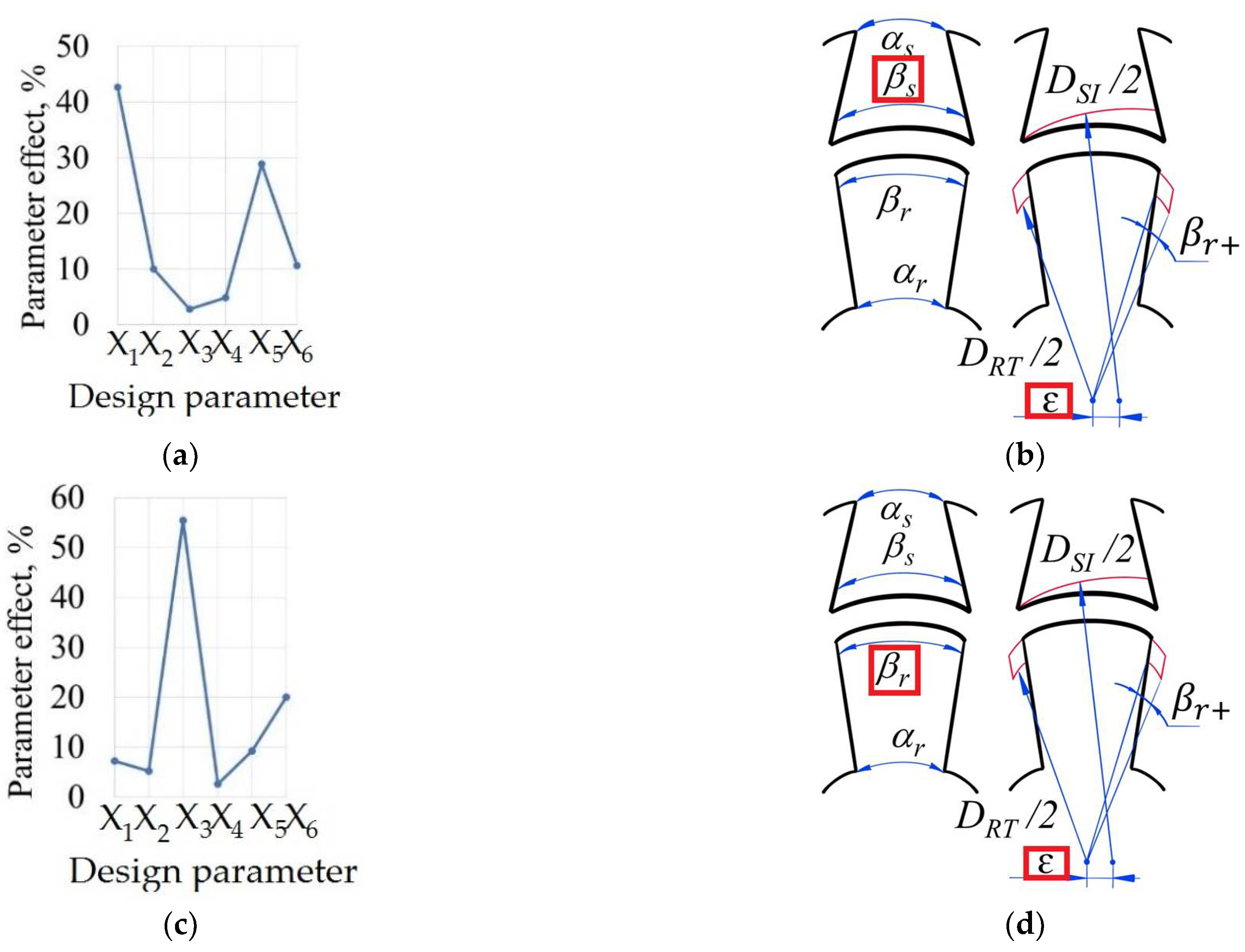
4.1. Results of the Sensitivity Analysis

The results of the sensitivity analysis, such as peak-to-peak values of the average torque and torque ripple, are shown in Figure 13 and Figure 14. Moreover, Figure 15 presents the overall influences of the design parameters on the objective functions.
It can be seen in the graphs above (see Figure 13 and Figure 15a) that the stator pole angle and the airgap shift variations have major influences on the average torque. The parameter effect value of the stator pole angle (X1) and airgap shift (X5) are 42% and 28%, respectively. Figure 13 suggests that the growth of the stator pole angle makes the average torque increase rapidly. This fact correlates with Equation (2), which defines θinc and the duration of torque production as a direct function of the stator pole angle. Meanwhile, the growth in the airgap shift reduces the average torque. One of the reasons could be a torque fall at the beginning of the overlap. On the other hand, the average torque has a nonlinear response to the change in the stator pole angle at the core and additional tooth angle on the rotor. There was a slight reaction noticed from the change in the rotor pole angle and the rotor tooth angle at the core.
If we now turn to the torque ripple analysis, we can conclude that the rotor pole angle has a principal influence on the torque ripple (see Figure 14 and Figure 15c). The parameter effect value of the rotor pole angle (X3) is more than 50%. Particularly, with the growth of the rotor pole angle, the torque ripple swiftly increases. The same tendency can be noticed for the growth of the additional tooth angle. This fact correlates with Equation (2), which illustrates that the duration of the maximum inductance θmax grows together with the rotor pole angle. One of the reasons that torque ripple increases along with the rotor pole angle could be that the SRM reaches the maximum inductance too fast and moves to a phase with no positive torque production. The air gap shift had a positive influence on the torque ripple reduction, as was expected. On the other hand, the advance in the stator pole angle and the reduction in the stator angle on the core slightly reduced the torque ripple.
It is worth taking a look at additional graphs which illustrate the influences of the changes in stator pole angle X1, airgap shift X5, and rotor pole angle X3 on the average torque. For that reason, Figure 16 presents the static torque curve for designs 1, 6, 11, 16, and 21 with the stator pole angle levels 1, 2, 3, 4, and 5, respectively (see Table 3).
It can be seen in the graph above that the increase in the stator pole angle leads to a wider area of torque production and consequent larger average torque. The drop in the torque at the beginning of the overlap in designs 6, 11, and 16 attracts particular attention. It may indicate the coeffect of the rotor pole angle X3 and rotor additional angle X6, which are higher in designs 6, 11, and 16.
Figure 17 presents the variation in the static torque with the change in both air-gap shift X5 and rotor pole angle X3. It is apparent from the figure that the average torque decreases. On the other hand, the area of the torque production shifted to the beginning of the overlap due to the growth of the rotor pole angle. Therefore, the area of zero torque enlarges at the end of the growing inductance phase when θmax = [30, 45]. It is important to highlight that the biggest improvement in the width of the torque and constancy of the torque at its maximum can be noticed between Design 1 and Design 2; θmax = [18, 30] and θmax = [22, 32], respectively. Due to the introduction of the airgap shift, the torque in design 2 became more stable at its maximum. However, further increase in the air-gap shift did not have a positive influence on the torque characteristic due to the possible influences of other parameters, such as additional tooth angle X6.
Due to the coeffect of the analyzed parameters on the resultant torque, it is important to keep in mind that Figure 16 and Figure 17 should be considered only together with Figure 13 and Figure 14.
The findings of the analysis of the results can be summarized as follows.
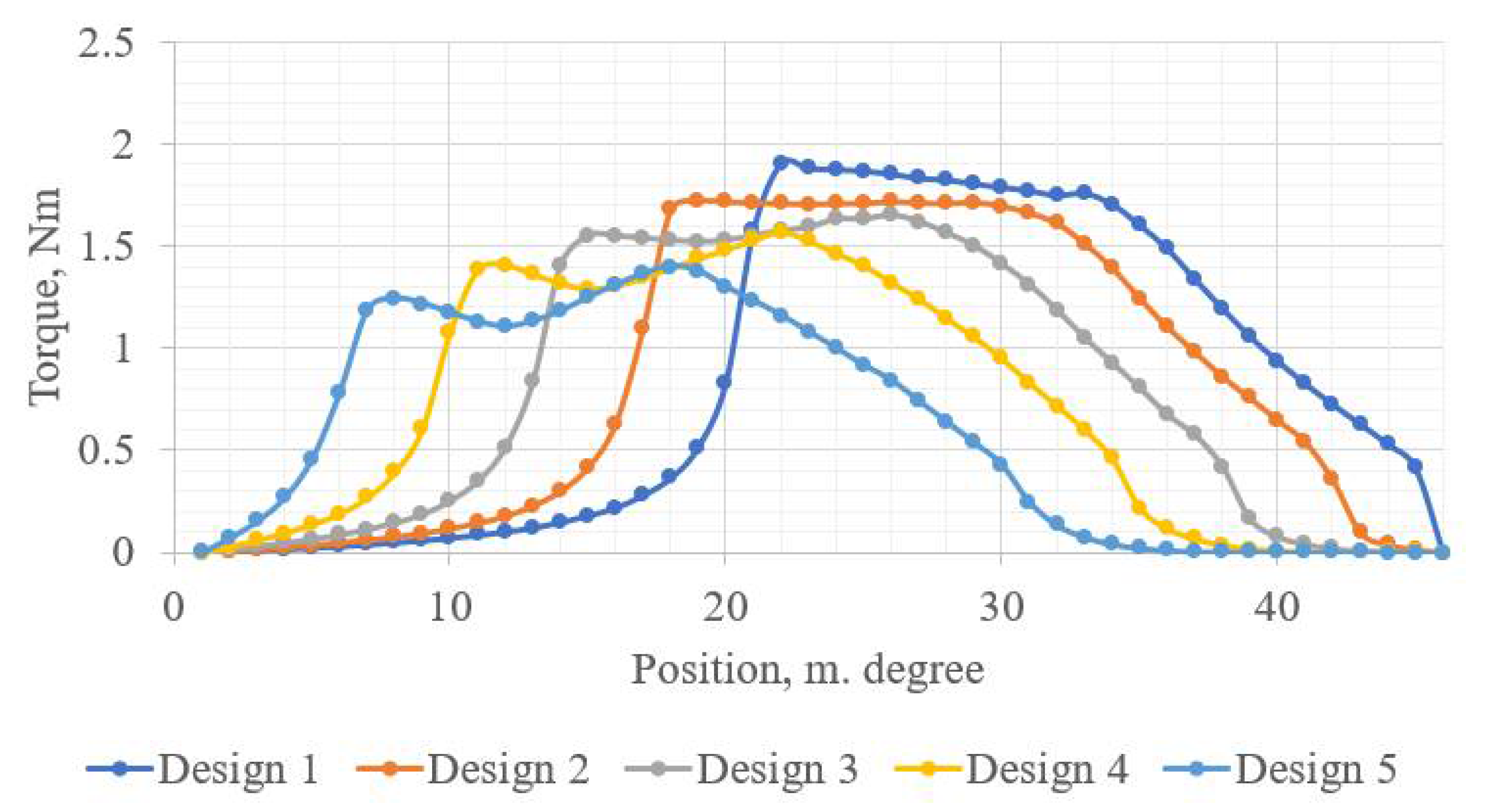
  • Stator pole angle has a major influence on the average torque. The increase in the stator pole angle leads to a wider torque production region and higher average torque.
  • The growth of the airgap shift has a positive influence on the torque ripple reduction and a negative influence on the average torque. The airgap shift raises the torque at the end of the growing inductance phase. However, the air-gap shift is a sensitive parameter, and its value should be selected carefully.
  • The increase in the rotor pole angle has a negative effect on the torque ripple. With the growth of the rotor pole angle, the torque curve shifts to the beginning of the torque production phase. To avoid the torque ripple with the increase in the rotor pole angle, the control turn-on and turn-off angles should be adjusted according to the area of torque production.
  • The introduction of the rotor pole angle within this SRM design leads to an increase in torque ripples. The possible explanation can be an improper selection of its values.

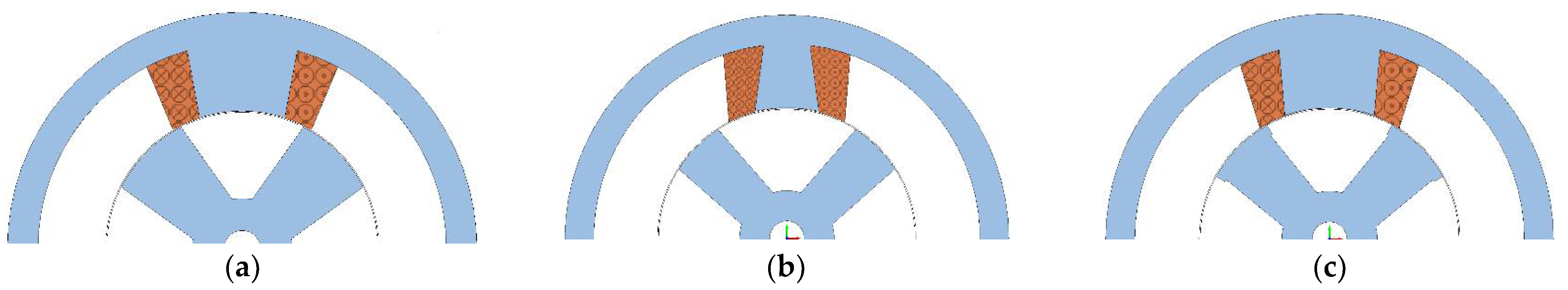
4.2. Topology Optimization Design Space Definition

With the aim of reducing the computational load during the topology optimization, the base design can be defined using the SA results. Moreover, the design domain of the topology optimization can be created based on the results presented in Section 3.
Table 4 and Figure 18 summarize the optimal designs according to the Taguchi SA. Based on Figure 13, Figure 14, Figure 15, Figure 16 and Figure 17, the best control factor sets in terms of average torque improvement and torque ripple reduction were chosen: first optimal design and second optimal design, respectively. The trade-off between these designs is defined in Table 4 as well. The trade-off design performed the average one-phase torque of 0.875 Nm, the total average torque of 1.31 Nm, and the torque ripple coefficient of 1.48.
To determine the design domain of the topology optimization, the following steps were performed:
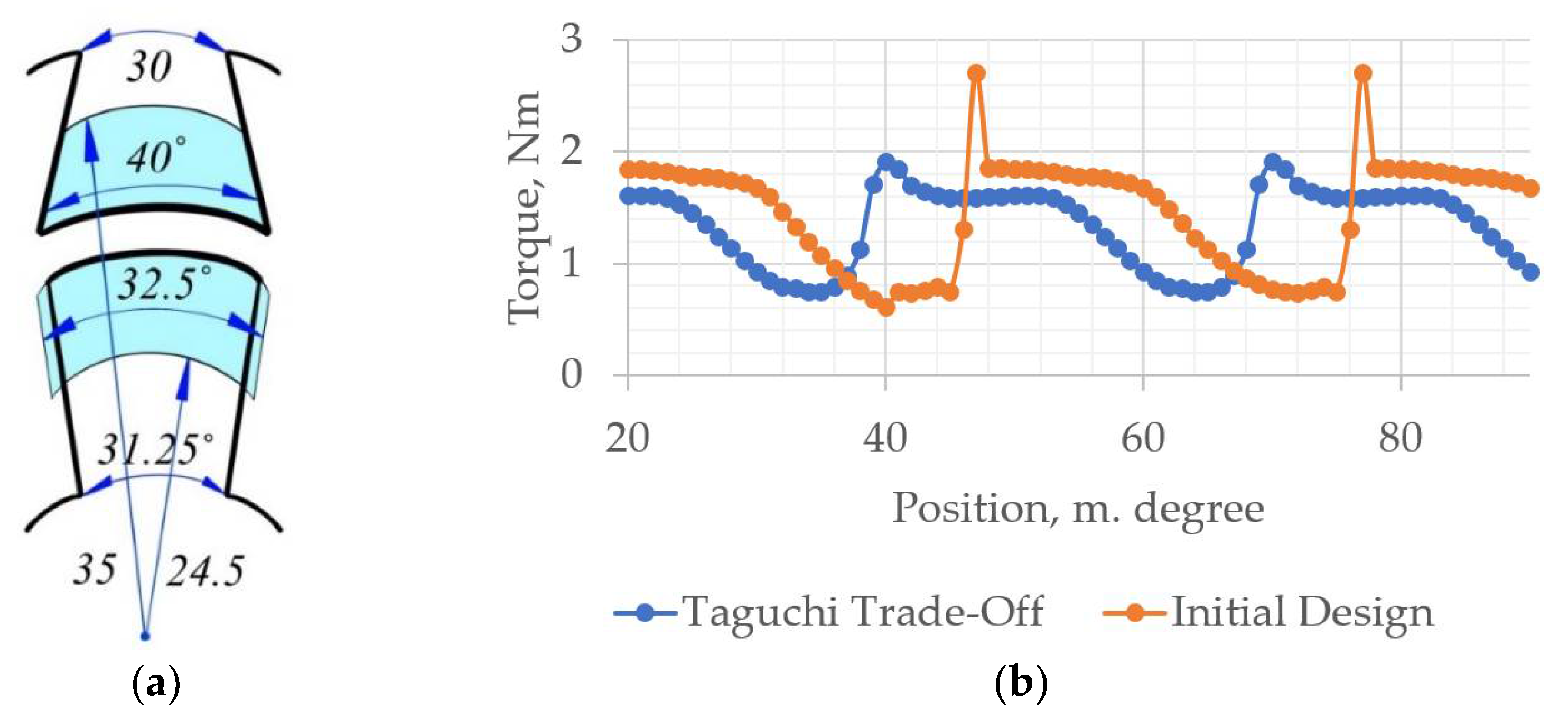
  • Stator pole angle was set to 40°, pursuing the best combination of maximum average torque and minimum torque ripple.
  • Stator pole angle at the core was set to 30°, insuring almost the lowest torque ripple and reasonably high torque.
  • The rotor pole angle and rotor pole angle at the core were set to 28.75° and 60°, respectively, trying to achieve the minimum torque ripple and keep the average torque ripple at the average level.
  • Due to the high influence of the airgap shift and the low influence of the core angles on the objective functions, the depth of the TO domain was set to 5 mm.
  • The possible additional angle for the rotor teeth was set to ±1.875° due to the highly negative influence of the additional teeth after 1.875 on both the average torque and torque ripple.
The base design for the future topology optimization will possess the following vector of the design parameters:
x = 40 , 10 , 28.75 , 31.25 , 0 , 0
Based on the results of the sensitivity analysis, the design domain of the topology optimization is defined in Figure 19a. Additionally, the torque comparison between the initial design and the trade-off design is presented in Figure 19b.

5. Conclusions

TO can be used as a powerful tool for design optimization while pursuing high performance for an SRM. On the other hand, TO is computationally expensive and geometrically restricted. To overcome the geometry restrictions, additive manufacturing techniques are proposed to be used for the optimized SRM. To overcome the issue of the computational complexity of the TO, the present research proposed a method of the TO design space reduction. To reduce the design domain of the SRM TO, and consequently reduce its computational burden, this research carried out SA to identify the minimum necessary design domain. To carry out the SA, the authors applied the Taguchi approach. The proposed method allowed the reduction of the design domain of the future TO considerably. Thanks to the applied SA, the most crucial areas of the three-phase SRM for future optimization were identified. Thereafter, the SA helped to define the TO design space that included only 25% of the whole body of the SRM. Thanks to the obtained minimum necessary design space of the motor, the computational complexity of the future TO was reduced by more than a half. The proposed method has significant implications for the TO computational burden reduction. Additionally, the proposed approach can be utilized for SRMs with different numbers of phases, stators, and rotor poles. Moreover, the presented SA of the motor design parameters can give a good overview of their influences on the average torque of the SRM and its torque ripple.
A natural progression of this work is to study the possibilities and restrictions of additive manufacturing for producing a topologically optimized SRM. As the second step, a we plan to carry out TO with respect to the results of the SA and additive manufacturing potentials and constraints. After obtaining the topologically optimized SRM, a prototype is to be manufactured and tested. More broadly, this research work could also focus on the application of the proposed approach for other motors’ TO.

Author Contributions

Conceptualization, E.A. and M.H.M.; methodology, E.A.; software, E.A. and H.H.; validation, E.A., M.H.M. and D.A.L.; formal analysis, E.A.; investigation, E.A.; resources, E.A.; data curation, E.A.; writing—original draft preparation, E.A.; writing—review and editing, H.H. and A.K.; visualization, E.A.; supervision, M.H.M., D.A.L. and A.K.; project administration, A.K.; funding acquisition, A.K. All authors have read and agreed to the published version of the manuscript.

Funding

This research was funded by the Estonian Research Council with grant PSG137, “Additive Manufacturing of Electrical Machines.”

Conflicts of Interest

The authors declare no conflict of interest.

References

  1. Rahman, K.M.; Fahimi, B.; Suresh, G.; Rajarathnam, A.V.; Ehsani, M. Advantages of switched reluctance motor applications to EV and HEV: Design and control issues. IEEE Trans. Ind. Appl. 2000, 36, 111–121. [Google Scholar] [CrossRef]
  2. Li, S.; Zhang, S.; Habetler, T.G.; Harley, R.G. Modeling, design optimization, and applications of switched reluctance machines—A review. IEEE Trans. Ind. Appl. 2019, 55, 2660–2681. [Google Scholar] [CrossRef]
  3. Madhavan, R.; Fernandes, B.G. Performance improvement in the axial flux-segmented rotor-switched reluctance motor. IEEE Trans. Energy Convers. 2014, 29, 641–651. [Google Scholar] [CrossRef]
  4. Lin, Z.; Reay, D.S.; Williams, B.W.; He, X. Online modeling for switched reluctance motors using b-spline neural networks. IEEE Trans. Ind. Electron. 2007, 54, 3317–3322. [Google Scholar] [CrossRef]
  5. Ma, C.; Qu, L. Design Considerations of Switched ReluctanceMotors with Bipolar Excitation for Low TorqueRipple Applications. In Proceedings of the 2013 IEEE Energy Conversion Congress and Exposition, Denver, CO, USA, 15–19 September 2013; Available online: https://digitalcommons.unl.edu/electricalengineeringfacpub/295 (accessed on 14 March 2022).
  6. Wang, W.; Luo, M.; Cosoroaba, E.; Fahimi, B.; Kiani, M. Rotor shape investigation and optimization of double stator switched reluctance machine. IEEE Trans. Magn. 2015, 51, 8103304. [Google Scholar] [CrossRef]
  7. Lee, J.W.; Kim, H.S.; Kwon, B.I.; Kim, B.T. New rotor shape design for minimum torque ripple of SRM using FEM. IEEE Trans. Magn. 2004, 40, 754–757. [Google Scholar] [CrossRef]
  8. Li, G.-J.; Ojeda, J.; Hlioui, S.; Hoang, E.; Lecrivain, M.; Gabsi, M. Modification in rotor pole geometry of mutually coupled switched reluctance machine for torque ripple mitigating. IEEE Trans. Magn. 2012, 48, 2025–2034. [Google Scholar] [CrossRef]
  9. Choi, Y.K.; Yoon, H.S.; Koh, C.S. Pole-shape optimization of a switched-reluctance motor for torque ripple reduction. IEEE Trans. Magn. 2007, 43, 1797–1800. [Google Scholar] [CrossRef]
  10. Sheth, N.; Rajagopal, K. Optimum Pole Arcs for a Switched Reluctance Motor for Higher Torque with Reduced Ripple. IEEE Trans. Magn. 2003, 39, 3214–3216. [Google Scholar] [CrossRef]
  11. Chen, H.; Yan, W.; Gu, J.J.; Sun, M. Multiobjective Optimization Design of a Switched Reluctance Motor for Low-Speed Electric Vehicles with a Taguchi-CSO Algorithm. IEEE/ASME Trans. Mechatron. 2018, 23, 1762–1774. [Google Scholar] [CrossRef]
  12. Omekanda, A.M. Robust torque and torque-per-inertia optimization of a switched reluctance motor using the Taguchi methods. IEEE Trans. Ind. Appl. 2006, 42, 473–478. [Google Scholar] [CrossRef]
  13. Hidaka, Y.; Igarashi, H. Topology Optimization of Synchronous Reluctance Motors Considering Localized Magnetic Degradation Caused by Punching. IEEE Trans. Magn. 2017, 53, 7000804. [Google Scholar] [CrossRef]
  14. Sato, S.; Sato, T.; Igarashi, H. Topology optimization of synchronous reluctance motor using normalized gaussian network. IEEE Trans. Magn. 2015, 51, 8200904. [Google Scholar] [CrossRef] [Green Version]
  15. Zhang, H.; Wang, S. Topology Optimization of Rotor Pole in Switched Reluctance Motor for Minimum Torque Ripple, Electric Power Components and Systems. Electr. Power Compon. Syst. 2017, 45, 905–911. [Google Scholar] [CrossRef]
  16. Okamoto, Y.; Hoshino, R.; Wakao, S.; Tsuburaya, T. Improvement of torque characteristics for a synchronous reluctance motor using MMA-based topology optimization method. IEEE Trans. Magn. 2017, 54, 7203104. [Google Scholar] [CrossRef]
  17. Ishikawa, T.; Yonetake, K.; Kurita, N. An optimal material distribution design of brushless DC motor by genetic algorithm considering a cluster of material. IEEE Trans. Magn. 2011, 47, 1310–1313. [Google Scholar] [CrossRef]
  18. DWhite, D.A.; Arrighi, W.J.; Kudo, J.; Watts, S.E. Multiscale topology optimization using neural network surrogate models. Comput. Methods Appl. Mech. Eng. 2019, 346, 1118–1135. [Google Scholar] [CrossRef]
  19. Andriushchenko, E.; Kallaste, A.; Belahcen, A.; Vaimann, T.; Rassõlkin, A.; Heidari, H.; Tiismus, H. Optimization of a 3D-Printed Permanent Magnet Coupling Using Genetic Algorithm and Taguchi Method. Electronics 2021, 10, 494. [Google Scholar] [CrossRef]
  20. Andriushchenko, E.; Kaska, J.; Kallaste, A.; Belahcen, A.; Vaimann, T.; Rassõlkin, A. Design Optimization of Permanent Magnet Clutch with Ārtap Framework. Period. Polytech. Electr. Eng. Comput. Sci. 2021, 65, 106–112. [Google Scholar] [CrossRef]
Figure 1. Three-phase 4/6 pole SRM structure.
Machines 10 00559 g001
Figure 2. SRM operation principle.
Machines 10 00559 g002
Figure 3. Ideal inductance profile of one SRM phase.
Machines 10 00559 g003
Figure 4. SRM drive: (a) SRM drive concept; (b) asymmetric bridge converter. LA–C denote to the phase inductances.
Machines 10 00559 g004
Figure 5. Commutation pattern of three-phase SRM drive.
Machines 10 00559 g005
Figure 6. Fringing flux at the beginning of overlap.
Machines 10 00559 g006
Figure 7. Ideal and real phase inductance comparison.
Machines 10 00559 g007
Figure 8. Design parameters.
Machines 10 00559 g008
Figure 9. SRM’s 2D FE model for one phase.
Machines 10 00559 g009
Figure 13. Peak-to-peak values of the average torque.
Machines 10 00559 g013
Figure 14. Peak-to-peak values of the torque ripple.
Machines 10 00559 g014
Figure 15. Control factors’ effects on the objectives: (a) average torque; (b) most influential parameters on average torque; (c) torque ripple; (d) most influential parameters on torque ripple.
Machines 10 00559 g015
Figure 16. Static torque curve for Taguchi designs with different levels of stator pole angle.
Machines 10 00559 g016
Figure 17. Static torque curve for Taguchi designs with different levels of air-gap shift and rotor pole angle.
Machines 10 00559 g017
Figure 18. (a) First optimal design; (b) second optimal design; (c) trade-off design.
Machines 10 00559 g018
Figure 19. (a) Topology optimization design domain; (b) Torque comparison of initial and trade-off designs.
Machines 10 00559 g019
Table 2. Design parameters’ sampling.
Design Parameter/Control FactorSymbolFactorLevel
12345
Stator pole angle (˚)βs = X1X12528.7532.536.2540
Stator pole angle at core (˚)αs= βs – X2X257.51012.515
Rotor pole angle (˚)βr = X3X32528.7532.536.2540
Rotor pole angle at core (˚)αr= βr + X4X42531.2537.543.7550
Airgap shift, mm ɛ =X5X500.250.50.751
Additional tooth angle (˚)βr+ = X6/2X603.757.511.2515
Table 3. Taguchi orthogonal array L25 (65) for 6 control factors and 5 levels and simulation results.
ExperimentControl FactorAverage TorqueTorque Ripple Coefficient
X1X2X3X4X5X6
11111110.8511.22
21222220.8381.06
31333330.7901.36
41444440.7161.55
51555550.6141.73
62123450.8081.16
72234510.7921.06
82345120.8991.37
92451230.8501.39
102512340.8120.95
113135240.8871.53
123241350.8291.55
133352410.8371.19
143413520.7960.92
153524130.9301.25
164142530.9361.52
174253140.8781.72
184314250.9071.30
194425310.8550.92
204531420.8561.02
215154320.9351.52
225215430.8470.94
235321540.8261.00
245432150.9011.43
255543210.9101.26
Table 4. Optimal designs according to the Taguchi SA.
Control Factor1st Optimal Design2nd Optimal DesignTrade-Off Design
X1425
X2153
X3412
X4222
X5142
X6312
Publisher’s Note: MDPI stays neutral with regard to jurisdictional claims in published maps and institutional affiliations.

