
Determination of Undercutting Avoidance for Designing the Production Technology of Worm Gear Drives with a Curved Profile

Institute of Mathematics, University of Miskolc, 3515 Miskolc, Hungary
Machines 2023, 11(1), 56; https://0-doi-org.brum.beds.ac.uk/10.3390/machines11010056
Submission received: 30 November 2022
/
Revised: 22 December 2022
/
Accepted: 28 December 2022
/
Published: 3 January 2023
(This article belongs to the Special Issue Advanced Processes and Technologies in Precision and Ultra-Precision Machining)
Abstract
:One of the most difficult production geometry tasks arising in the machining process of the elements of a drive pair is to avoid undercuts. It is a serious technological challenge to determine the production of the elements of worm gear drives avoiding the phenomenon undercut, especially in the case of a pair consisting of a curved profile worm and its mating wheel. The technology of forming the tooth surface requires a separate examination in each case, running the simulation procedure of the tool geometry and the movement conditions when forming different teeth. This article proposes a new concept for determining and then avoiding the positions of undercutting by examining the patented worm with a circular arc profile in axial section, due to its extremely advantageous aspect in terms of production technology. The cutting edge of the hob, formed from the substitutional worm, moves on the tooth surface of the worm, and produces the tooth surface of the conjugate wheel. The gear tooth surface has been determined based on the main law of gearing with the lines consisting of the contact points of the conjugated surfaces. The conditions for the disappearance of the common normal or the relative velocity fitting to the common tangent plane of the contacting points are defined in this paper.
1. Introduction
Gear theory belongs to the scientific fields of constructive geometry, manufacturing, design, measurement technology and computer methods. All these disciplines are necessary for modern developments [1,2,3], some of which have affected our research work at the Worm Gear Science School [4,5], which was founded at the University of Miskolc. Gear tooth theory has evolved into an independent discipline following much theoretical and practical research [6,7,8]. Works about examining the necessary and sufficient conditions for the existence of an envelope have also influenced our research (e.g., [9,10]). With the development of gear technology and the use of computers both in gearing theory and gear manufacturing, researchers have modified it to a modern theory of gearing and extended its methodology [10] and industrial applications [11,12,13]. Many researchers dealing with this topic have had a significant impact on our work [13,14]. Our studies have also been influenced by writings focused on the study of undercuts in involute shafts and bevel gears [15,16]. For the present work, tool profile distortion analysis in the case of the machining of worm gear drive pairs with a circle arc profile in the axial section has been completed using the methods of the constructive geometry [17,18,19]. Studies supported by valuable simulation procedures have been performed for the contact analysis of the drive pair elements, which were also useful in the research leading to the present paper [20,21]. Particularly noteworthy is the research on the industrial implementation of the production of cylindrical worms, supported by theory, for the purpose of this paper [22,23].
In this article, an undercutting analysis in relative motion is presented, which can occur even if there is no singular point on the generating surface. At singular points the surface normal vectors become indeterminate, so undercutting can occur. The analysis has been performed in a constructive geometric model created for the development of the production geometry of the elements of a conical and cylindrical worm gear pair (see Figure 1). The rotating coordinate system K1F(x1F, y1F, z1F) has been fixed to the worm or hob, while the rotating coordinate system K2F(x2F, y2F, z2F) has been fixed to the gear or grinding wheel, the coordinate system K1(x1, y1, z1) has been connected to the linear moving table, the stationary coordinate system K2(x2, y2, z2) has been connected to the grinding wheel or gear, and the stationary coordinate system K0(x0, y0, z0) has been fixed to the frame.
The geometrical parameters used, such as a for the distances of axes, c for the tool offset, α for the tilting angle of the tool to the helical surface in a characteristic section, γ12 for the angle between worm and wheel or tool axes, which is equal to helix lead angle γ on the worm’s reference surface in case of manufacturing with a grinding wheel, pa for the axial screw parameter, pr for the radial spiral parameter, and zax for axial displacement of the helicoid surface to the manufacturing position, are indicated in Figure 1. The motion geometrical parameters used, such as φ1 for the rotation angle of the helical surface, φ2 for the rotation angle of the gear or the tool surface, ω1 for the angular velocity of the helical surfaces and ω2 for the angular velocity of the gear or the tool, have been specified as shown in Figure 1. In the case of the reported constructive geometric model, the geometric parameters must be set according to the task. In the case of worm gear drive meshing analysis, the shaft angle γ12 is −90°, taking into account the orientation of the axes. Our further analyses relate to the examination of rigid bodies. In this discussion, the worm gear hob created from the worm is labeled Σ1 and the derived gear tooth surface Σ2 to differentiate between generator and generated surfaces.
For the analysis, the vector parametric form of the regulator helical surface Σ1 in the coordinate system K1F will be suitable:
where η is the internal distance parameter and ϑ is the internal angle parameter. The regulator surface Σ1 is free from singularities if the normal vectors exist, so the following condition is fulfilled:
The transformation matrix between the coordinate system K1F and the coordinate system K2F can be determined based on Figure 1
The transformation matrices M1,1F and M1F,1 based on Figure 1 are as follows
The transformation matrices M0,1 and M1,0 based on Figure 1 are as follows
The transformation matrices MK,0 and M0,K based on Figure 1 are as follows
The transformation matrices M2,K and MK,2 based on Figure 1 are as follows
The transformation matrices M2F,2 and M2,2F based on Figure 1 are as follows
The matrix of the transformation from the frame K2F to the frame K1F is as follows
The matrix of the transformation from the frame K1F to the frame K2F is as follows
The v2F(12) relative velocity vector between surface Σ1 and surface Σ2 can be determined using the transformation matrix M2F,1F from the frame K1F(x1F, y1F, z1F) of the worm to the frame K2F(x2F, y2F, z2F) of the mating gear, in the form
Using the transformation matrix M1F,2F from the frame K2F(x2F, y2F, z2F) of the mating gear to the frame K1F(x1F, y1F, z1F) of the worm, the relative velocity vector v1F(12) can be calculated according to the following formula
where the “kinematic transformer” matrix is based on [18]:
where the P1a is as follows
The equation of meshing can be written in the following form
The tooth surface Σ2 can be produced as the enveloping surface of the instantaneous contact lines in such a way that any contact point C of the contact lines l described in K1F can be converted into the frame K2F using the transformation matrix M2F,1F between them, which can be written
The geometric location of those points of the lφ1 contact curves occurring for any φ1 parameter should be determined on the generator surface Σ1, which results in singular points on the generated gear tooth surface Σ2.
2. Singularity Avoidance Method
Different points of the tooth surfaces created by the tool surfaces can be distinguished from the perspective of differential geometry.
Definition 1.
By elementary surface we mean a shape that can be produced as the endpoints of the position vectors of a two-parameter vector function interpreted on a simply connected region of the plane , where
- (a)
- the mapping defined byis topological
- (b)
- is continuously differentiable
- (c)
- vectorsandare not parallel at any point.
Those surface productions that fulfil the conditions (a)–(c) are called regular productions.
Definition 2.
A point that does not meet the definition of a regular point is called a singular point.
To avoid undercutting it is necessary to determine the geometrical location of the points on the regulator surface Σ1 that create the singular points on the regulated surface Σ2, where the velocity vector or the normal vector of the surface become indeterminate, resulting in undercutting.
Undercutting during relative motion can also occur even if there is no singular point on the regulator surface Σ1, but the generated surface Σ2 may contain not only regular points but also singular points.
In order to carry out the matrix algebraic analysis, it is necessary to make some definitions regarding the projections falling on the coordinate planes.
Definition 3.
Let the value of the determinant of matrix
bein the mathematical kinematical model.
Definition 4.
Let the value of the determinant of matrix
be in the mathematical kinematical model.
Definition 5.
Let the value of the determinant of matrix
be in the mathematical kinematical model.
Definition 6.
Let the value of the determinant of matrix
bein the mathematical kinematical model.
The contact point C is located on both the generator surface Σ1 and the generated surface Σ2 at the same time. To determine the relative velocity, the contact point C should be examined simultaneously as point C(1) fitted to the generator surface Σ1 and as point C(2) fitted as to the generated surface Σ2. The relative velocity v(12) of the contact point C can be represented as the velocity of point C(1) with respect to point C(2) by the following equation
where v(i) are the velocity vectors of the coincident points C(i) of surface Σi, and i is the index of the frame in which the velocity is written.
If a regular point of Σ1 generates a singular point on the meshed surface Σ2, then using the equality of the absolute velocity vectors of the contact points Ci the following equation must be fulfilled:
where v(i) (i = 1, 2) are the velocity vectors of the contacting points on the portant surfaces in the common tangent plane.
The differentiation of function according to the time parameter t from Equation (6) helps to filter the points on Σ1, which generates singular points on Σ2 as follows:
Theorem 1.
In order for the surface Σ1 with regular points to create singular points on the surface Σ2 enveloped by it, the sufficient condition is the fulfilment of the next equation
Proof of Theorem 1.
Equations (23) and (24) in the frame K1F of the mathematical kinematical model result in the forms
contributing to the elimination of points on the surface Σ1, that generate singular points.
□
From Equations (26) and (27) prescribing , an overdetermined system of four linear equations arises with two unknowns, which are and . This system leads to the matrix G4×3 with rank r = 2 and a certain solution for the unknowns
The G4×3 yields on the coordinate planes in our kinematical model to the determinants of the matrices , , and , which respectively take the value , , and .
The yields to the equation of meshing [9], and it is fulfilled for the contact points of surfaces Σ1 and Σ2, which are taken into account during the tests. Thus only the equalities , and need to apply to determine the singularity conditions of the surface, which procedure yields to the sufficient condition .
The simultaneous fulfilment of equations
determines the points on the surface Σ1 that form singular points on the surface Σ2.
The presented procedure is a suggested way to determine the singularities on the created surface and thus to avoid its undercutting during production.
Through G4×3 it is possible to study different types of helicoid drives.
3. Application
In the following, the analysis will have been applied to a cylindrical worm with circular arc profile in the axial section and its connected gear.
The gear is machined with a hob derived from the worm, designed using a complicated mathematical process [10,18]. The solid model of the simultaneous coupling wheel, worm and hob is shown in Figure 2.
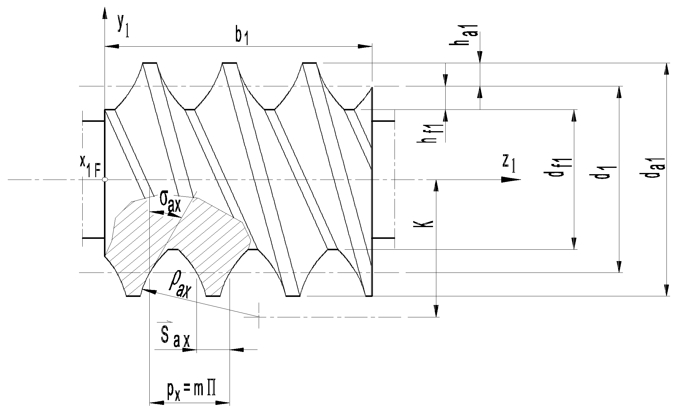
The geometrical parameters of the worm profile, such as the radius of the circle arc ρax, the distance between the worm axis and the center of the profile circle K are shown in Figure 3.
Based on Figure 1, the manufacturing geometry of cylindrical worm drives with parameters α = 0, c = 0, pr = 0 and γ = −90° can be examined using the kinematic model. The coordinates of the helical surface with circular arc profile curve in axial section can be written in the next form
The normal vectors of this worm surface can be described as follows
Based on (4) the coordinates of the relative velocity vector are calculated in the form
With the method outlined, the elements of G4×3 can be calculated with a clear mathematical process [25]. The elements of the determinants of Equation (26) derived from r1F can be found in the following formulas
The element of the matrix G4×3 is presented in the equation
And the element of the matrix G4×3 is presented in the following equation
Similarly to the previous calculations, the element of the matrix G4×3 is as follows
The parameters indicated in the input part of the table are the geometrical parameters of the worm gear drive, and the information on the movement and surface parameters. The output part of the table contains the coordinates of the meshing knotes KA and KB, as well as the value of the meshing opening angles βA and βB.
The equations represented by matrix G4×3 allow our computer program to determine the points of curve L on surface Σ1, which generate singular points on the Σ2. The qualification of procedure is shown in the case of a particular cylindrical worm gear drive with circle arc profile in worm axial section [11,18].
In case of the worm gear drive with geometrical and precision parameters z1 = 3, m = 12.5, γ0 = 21°2′15′′, ρax = 50, = 10 to set addendum to the reference line on tooth, size of worm tooth chord, a = 280, d01 = 97.5, H = 117.809722, δax = 24°31′10′′, z2 = 35, Fr1 = ±0.017, fp1 = ±0.016, fγ = ±0.018, ff = 0.08 [11], the contact points are presented in projection on the coordinate plane [x1F, y1F] in Figure 4.
The geometric location of the nodes KA and KB occurring for each value of φ1 are the lines LA and LB. The position of LA and LB curves is illustrated in Figure 5.
For the cylindrical arched worm, LA and LB curves can be found having points to cause the singularity on the gear tooth surface. To avoid undercutting on the gear surface Σ2, it is sufficient to delimit the worm surface Σ1 during design by eliminating the LA and LB curves.
The patented worm and the connected gear have been manufactured with the given parameters, as it can be seen in Figure 6.
4. Discussion
The different drives, which were mostly investigated by simulation methods in excellent papers [12,14,15,20,21], can now be determined using a targeted calculation procedure. Until now, the matrix algebra solution was performed separately for each type of gear pair in its own frame, but this paper presents a step towards generalization. In the model developed for production geometry developments used here, an experiment in the direction of generalization using the methods of matrix algebra was presented, as opposed to the tests carried out separately for each type of gear pair until now.
The worm with a circular profile in the axial section was patented due to its outstanding advantages from the point of view of production technology. Undercutting has not yet appeared in the literature dealing with the manufacturing geometrical problems of a cylindrical worm with a circular profile in the axial section and the related gear [4,11,17,18,19], whose deficiencies in this field has been fulfilled by this study. The processing of the worm wheel connected to this worm was examined in this paper with the aim of determining the possible locations of undercutting occurring during production. The cutting edge of the worm gear hob made from a worm with strict manufacturing geometrical conditions forms the tooth surface of the gear. According to the tests carried out by means of matrix algebra procedures, as a result of a computer program run with specified data, the points of the characteristic curves of the worm that make up the nodes can create singular points on the tooth surface of the gear. In order to avoid undercutting, it is advisable to exclude knot lines when determining the limits of the worm during designing.
5. Conclusions
This paper dealt with the problematics of avoiding undercutting in the general mathematical kinematic model. The undercut can be mapped in the case of a helical drive with a circular profile in the axial section by taking into account the mutual influence of the relationships of the interacting mathematical parameters. If these interacting parameters are performed in one model with one procedure, it is desirable to perform them in the case of other worm drives as well.
Funding
This research received no external funding.
Institutional Review Board Statement
Not applicable.
Informed Consent Statement
Not applicable.
Acknowledgments
I express my gratitude to Illés Dudás† retired and then deceased professor of the University of Miskolc, and the Worm Gear Scientific School founded by him. I express my grateful thanks to the difiCAD Engineering Office for providing the industrial background necessary for research. I hereby express my gratitude to the instructors of the University of Miskolc for their support, who provided me with ideas, encouragement and advice.
Conflicts of Interest
The authors declare no conflict of interest.
References
- Ou, Y.; Xing, Y.S.; Wang, K.; Zhou, C.G.; Feng, H.T. Investigation of crucial geometric errors of screw grinder for ball screw profile parameters. Int. J. Adv. Manuf. Technol. 2022, 118, 533–550. [Google Scholar] [CrossRef]
- Gao, H.; Lu, S.; Yang, A.; Bao, Y. A methodology for helical mill-grinding of tiny internal threads made of hard brittle materials. Int. J. Adv. Manuf. Technol. 2017, 91, 25–37. [Google Scholar] [CrossRef]
- Shen, Y.; Liu, X. Computer-integrated shaving processing for spiroid face gear on a five-axis CNC machine. Int. J. Adv. Manuf. Technol. 2018, 97, 1061–1070. [Google Scholar] [CrossRef]
- Dudás, I. The extension of the general mathematical model developed for helicoidal surfaces to the whole system of manufacturing technology and production geometry (ProMAT). Int. J. Adv. Manuf. Technol. 2016, 86, 1557–1572. [Google Scholar] [CrossRef]
- Balajti, Z.; Dudás, I. The Monge Theorem and Its Application in Engineering Practice. Int. J. Adv. Manuf. Technol. 2017, 91, 739–749. [Google Scholar] [CrossRef]
- Willis, R. Principles of Mechanism; Cambridge University Press: London, UK, 1841. [Google Scholar]
- Buckingham, E. Design of Worm and Spiral Gears; The Industrial Press: New York, NY, USA, 1960. [Google Scholar]
- Dudley, D.W. Gear Handbook; MC Graw Hill Book, Co.: New York, NY, USA; Toronto, ON, Canada; London, UK, 1962. [Google Scholar]
- Zalgaller, V.A. Theory of Envelopes; Publishing House Nauaka: Moskow, Russian, 1975. [Google Scholar]
- Litvin, F.L.; Fuentes, A. Gear Geometry and Applied Theory; Cambridge University Press: New York, NY, USA, 2004. [Google Scholar]
- Dudás, I. The Theory and Practice of Worm Gear Drives; Penton Press: London, UK, 2000. [Google Scholar]
- Tomori, Z. An Optimal Choice of Profile Shift Coefficients for Spur Gears. Machines 2021, 9, 106. [Google Scholar] [CrossRef]
- Dudás, L. Modelling and simulation of a new worm gear drive having point-like contact. Eng. Comput. 2013, 29, 251–272. [Google Scholar] [CrossRef]
- Bendefy, A.; Horák, P. Gear pair generation with the method of transposed lines of action. In Proceedings of the 14th International Design Conference, DESIGN 2016, Zagreb, Croatia, 16–19 May 2016; pp. 129–136. [Google Scholar]
- Máté, M.; Hollanda, D.; Tolvaly-Roşca, F.; Forgó, Z.; Egyed-Faluvégi, E. Synthesis of a Profile Errorless Involute Shaper Cutter with Cylindrical Rake Face. In Proceedings of the 2019 IEEE 19th International Symposium on Computational Intelligence and Informatics and 7th IEEE International Conference on Recent Achievements in Mechatronics, Automation, Computer Sciences and Robotics (CINTI-MACRo), Szeged, Hungary, 14–16 November 2019; pp. 71–78. [Google Scholar] [CrossRef]
- Hodgyai, N.; Tolvaly-Roșca, F.; Máté, M. The Conditions of Undercut by Shaping Using a Rounded Profile Gear Shaper Cutter. Pap. Tech. Sci. Tech. Sci. Dep. Transylv. Mus.-Soc. 2021, 14, 30–36, (In Romania ). [Google Scholar]
- Balajti, Z.s.; Ábel, J.; Dudás, I. Examination for post-sharpening adjustment of cutting edge of a worm gear hob with circle arched profile in axial section. Procedia Manuf. 2021, 55, 260–265. [Google Scholar] [CrossRef]
- Balajti, Z. Development of Production Geometry of Kinematical Drive Pairs. Ph.D. Dissertation, University of Miskolc, Miskolc, Hungary, 2007; p. 126. (In Hungarian). [Google Scholar]
- Balajti, Z. Examination and adjustment of bearing pattern in case of helicoid drives. Procedia CIRP 2018, 77, 267–270, ISSN 2212-8271. [Google Scholar] [CrossRef]
- Popkonstantinovic, B.; Stojicevic, M.; Jeli, Z.; Obradovic, M.; Popa, D.L. Simulation and Motion Study of Mechanical Integrator 3D Model. FME Trans. 2019, 47, 299–303. [Google Scholar] [CrossRef]
- Bucur, C.; Máté, M. Theoretical Peculiarities Regarding the Definition and Representation of the Rolling Surfaces for Chain Transmission. Procedia Eng. 2017, 181, 206–213. [Google Scholar] [CrossRef]
- Boral, P.; Gołębski, R. Technology of Manufacturing of ZC Cylindrical Worm. Materials 2022, 15, 6412. [Google Scholar] [CrossRef] [PubMed]
- Kacalak, W.; Majewski, M.; Budniak, Z.; Ponomarenkow, J. Worm Gear Drives with Improved Kinematic Accuracy. Materials 2021, 14, 7825. [Google Scholar] [CrossRef] [PubMed]
- Dudás, I.; Drobni, J.; Ankli, J.; Garamvölgyi, T. Equipment and Procedure for Profiling a Grinding Wheel Suitable for the Geometrically Correct Production of a Worm Drive Pair with a Curved Profile in the Main Section. Patent 170118, 27 December 1983. [Google Scholar]
- Vadászné Bognár, G. Mathematic for IT specialists and Engineers 2; University Press of Miskolc: Miskolc, Hungary, 2003; p. 347. ISBN 9636615764. [Google Scholar]
Figure 1.
The frames defined for the analysis of the production geometry of the surface Σ1 of the worm and the Σ2 of the wheel, based on [18].
Figure 1.
The frames defined for the analysis of the production geometry of the surface Σ1 of the worm and the Σ2 of the wheel, based on [18].

Figure 2.
The worm gear drive and the hob derived from the worm [17].
Figure 2.
The worm gear drive and the hob derived from the worm [17].

Figure 3.
The cylindrical worm with a circle arc profile in axial section with the profile parameters, as the distance K between the arc center and the worm axis, and the arc radius ρax at standard marks, which has been patented [11,17,18,19,24].

Figure 4.
The projection of the contact points of the contact lines in the plane [x2F, y2F] with the marked knots KA and KB, and their equal coordinates YA and YB indicated by highlighting.
Figure 4.
The projection of the contact points of the contact lines in the plane [x2F, y2F] with the marked knots KA and KB, and their equal coordinates YA and YB indicated by highlighting.

Figure 5.
Contact lines with the LA and LB curves on the worm surface Σ1.

Figure 6.
The manufactured worm wheel drive pair.

Disclaimer/Publisher’s Note: The statements, opinions and data contained in all publications are solely those of the individual author(s) and contributor(s) and not of MDPI and/or the editor(s). MDPI and/or the editor(s) disclaim responsibility for any injury to people or property resulting from any ideas, methods, instructions or products referred to in the content. |
© 2023 by the author. Licensee MDPI, Basel, Switzerland. This article is an open access article distributed under the terms and conditions of the Creative Commons Attribution (CC BY) license (https://creativecommons.org/licenses/by/4.0/).
Share and Cite
MDPI and ACS Style
Balajti, Z. Determination of Undercutting Avoidance for Designing the Production Technology of Worm Gear Drives with a Curved Profile. Machines 2023, 11, 56. https://0-doi-org.brum.beds.ac.uk/10.3390/machines11010056
AMA Style
Balajti Z. Determination of Undercutting Avoidance for Designing the Production Technology of Worm Gear Drives with a Curved Profile. Machines. 2023; 11(1):56. https://0-doi-org.brum.beds.ac.uk/10.3390/machines11010056
Chicago/Turabian StyleBalajti, Zsuzsa. 2023. "Determination of Undercutting Avoidance for Designing the Production Technology of Worm Gear Drives with a Curved Profile" Machines 11, no. 1: 56. https://0-doi-org.brum.beds.ac.uk/10.3390/machines11010056
Note that from the first issue of 2016, this journal uses article numbers instead of page numbers. See further details here.