
Localization of Mobile Manipulator in Vineyards for Autonomous Task Execution

Laboratory for Robotics and Intelligent Control Systems (LARICS), Faculty of Electrical Engineering and Computing, University of Zagreb, Unska 3, 10000 Zagreb, Croatia
*
Author to whom correspondence should be addressed.
Machines 2023, 11(4), 414; https://0-doi-org.brum.beds.ac.uk/10.3390/machines11040414
Submission received: 18 February 2023
/
Revised: 16 March 2023
/
Accepted: 17 March 2023
/
Published: 23 March 2023
(This article belongs to the Special Issue Modeling, Sensor Fusion and Control Techniques in Applied Robotics)
Abstract
:Although robotic systems have found their place in agriculture, there are still many challenges, especially in the area of localization in semi-structured environments. A robotic system has been developed and tested to perform various tasks in the steep vineyards of the Mediterranean region. In this paper, we describe a method for vine trunk localization, based solely on the visual recognition of vine trunks by neural networks fed by an RGB camera. Assuming that the height of the first wire in the vineyard is known, the proposed method is used to determine the location of vines in the immediate vicinity of the all-terrain mobile manipulator—ATMM-VIV—needed for spraying and bud suckering. The experiment was conducted in a slightly inclined vineyard to evaluate the proposed localization method.
1. Introduction
Robotics is rapidly transforming agriculture, with an increasing focus on the affordable and effective automation of agricultural processes [1]. This technology belongs to a class of professional service robots and has significant applications in viticulture, one of the most challenging areas of agriculture [2,3]. Vineyards, especially those located on slopes, are very labor-intensive, and conventional machinery is often unsuitable for rocky terrain, such as that found in the Mediterranean region. In addition, unfavorable working conditions have led to a shortage of labor, compelling farmers to look for advanced technological solutions to address these problems [4,5].
A steep slope vineyard is a semi-structured environment. On the one hand, a vineyard can be considered unstructured because each vine is different and the terrain and soil conditions can also vary. The soil surface can be rough, uneven, grassy, or rocky. In addition, vineyards are often located on slopes. On the other hand, the vineyard has a certain internal structure. In most modern vineyards, the vines are planted in an orderly fashion, mostly in straight rows and at prescribed intervals. The aisles are wide enough for tractors to pass between them. On steep slopes, on the other hand, the rows of vines follow the surface of the terrain. The width of the aisles between the rows of vines may vary. Regular agricultural maintenance of vineyards is labor intensive and requires a lot of manpower (weeding, pruning, bud suckering, spraying, and harvesting). In addition, steep slopes can make this work even more demanding. The use of autonomous robots for such work offers the possibility of facilitating vineyard maintenance and improving the health of farmers.
Our research focuses on the navigation required for two challenging tasks in viticulture: suckering and spraying. In steep slopes, these tasks are typically performed by hand, which can lead to unnecessary ecological damage. It has been shown that, in conventional viticulture, up to 95% of chemicals end up in the soil and water [6]. The use of a robotic system can help mitigate these drawbacks by allowing for the precise application of chemicals to specific parts of the vines.
In this paper, we describe a local tracking system that detects vine trunks using a simple camera and extracts all necessary localization data from it. We also experimentally examined the possibility of using the proposed vine trunk detection as a navigational goal. Although the basic theoretical background of this research is well-known, to the best of the author’s knowledge there has been no practical implementation in such a complex environment as a vineyard. In this paper, we investigate the implementation of a monocamera approach to localization in a vineyard, which can be considered as a semi-structured environment.
The present work is organized as follows. Section 1.3 describes the approach used in the HEKTOR project. Section 2 presents the state of the art in navigation in semi-structured environments, focusing on navigation in vineyards and autonomous task execution. Subsequently, Section 3 presents the localization of vine trunks. Experimental verification of the proposed solution is shown in Section 4. Section 5 concludes the paper with an outlook on future work.
1.1. HEKTOR Project
The research presented in this paper is part of the HEKTOR project (hektor.fer.hr, accessed on 16 March 2023). The goal is to pave the way for the use of robotic technology in two challenging agricultural fields: viticulture and mariculture. The goal is to develop a heterogeneous, modular, and autonomous robotic system suitable for various inspection and intervention tasks [7,8]. In addition, the goal of the HEKTOR project is to provide a systematic solution for the coordination of intelligent heterogeneous robots/vehicles (marine, land, and air) capable of autonomous cooperation and task distribution in open, unstructured space/water. Mission planning for such systems will seek a multi-level control structure that combines high-level planning and coordination with low-level reactive execution. However, this paper focuses on the challenges of navigation in viticulture. The HEKTOR system is a robotic system consisting of four different types of robots that communicate and collaborate via a ROS-based middleware. Thought of on a large scale, such a solution could help the potential end users (winemakers) save more time in the wine production life cycle by moving to fully automated vine suckering and spraying tasks. These tasks will be carried out in the steep sloped karst landscape of the Mediterranean region.
The experimental field for HEKTOR is field T10 in the Jazbina vineyard of the Faculty of Agriculture, University of Zagreb, shown in Figure 1.
1.2. All-Terrain Mobile Manipulator- ATMM-VIV
The all-terrain mobile manipulator VIV (ATMM-VIV) is a four-tracked skid-steered field research platform capable of autonomous movement in a variety of challenging environments, including ruins, stairwells, and terrain with steep slopes. The existing hardware was equipped with an Intel® NUC 10 i7FNK running Ubuntu 20.04 with ROS Noetic, which serves as the primary processing and control computer. Robosense RS-LiDAR-16, a lightweight omnidirectional laser radar with 16 beams, was mounted at the central position of the robot. To increase mapping accuracy, a Pixhawk autopilot was mounted on the robot, which provided IMU measurements and served as an interface between the ATMM-VIV on-board control system and the GNSS subsystem. Additionally, mounted on the front of the robot are two cameras, the Intel Realsense D435 depth camera, and the Intel Realsense T265 tracking camera.
The drivetrain provides effective mobility in difficult terrain and enables the transport of large loads. ATMM-VIV has four tracks mounted on adjustable flippers. These flippers can be manually rotated 360 degrees and placed in any of the 12 predefined positions. In our work, the flippers are always fixed in the rear-facing position. The ATMM-VIV is a skid-steered vehicle, which makes the use of odometry unreliable. This kinematic constraint is important for positioning ATMM-VIV in close proximity to vines. ATMM-VIV can be equipped with a variety of tools, such as a suckering tools or a robotic arm, as shown in Figure 2. The first is a compliant robotic end effector for bud suckering, presented in [9]. The ATMM-VIV can also have a robotic arm, KINOVA Gen3 7DoF, which can be equipped with two different end effectors. The brush end effector is used for precise and selective suckering [10]. The spray nozzle is attached for precise, selective spraying, as shown in [11]. In addition, the mobile manipulator has a 30-L liquid tank that provides the liquids required for spraying tasks.
1.3. HEKTOR Vineyard Navigation
One goal of global path planning is to ensure that all vineyard aisles are passed by ATMM-VIV, as shown in [12]. The vineyard is surveyed by the drone, and key navigation points (entrances and exits of each aisle) are determined, as shown in Figure 3. In addition, the robot changes its orientation, while navigating through the aisle, especially in vineyards on steep slopes, uneven terrain, and mountains. Such behavior can cause important environmental features to be lost from the field of view. Figure 4 shows three cases. Uneven terrain can also cause the same problem, only in the other direction. Figure 5 illustrates how the field of view can be affected by a steeply sloping vineyard, especially when the robot is placed at the top of the slope.
In addition, when navigating for the spraying task, the mobile manipulator must maintain a certain distance from the vines to ensure optimal spraying performance. The distance is even more important when a compliant robotic end effector for vine suckering is used because the flexible rubber bands on the rotating shaft are only 20 cm long, which severely limits the navigation in the aisle. For the third task, intended for ATMM-VIV, the KINOVA Gen3 robotic arm is used in the version with seven degrees of freedom. The arm used in our case has a reach of cm. Therefore, the maximum distance that can be between the robot and the vine trunk is given as . Moreover, three characteristic cases can be distinguished, which are shown in Figure 6. Therefore, ATMM-VIV must ensure that the entire vine trunk is within the working range of the robot arm.
To accomplish the autonomous task, ATMM-VIV must solve several nested problems, shown in Figure 7. First, ATMM-VIV must precisely navigate in a semi-structured environment to position itself at the entrance of the desired aisle. Once the robot is inside the aisle, it can move to the first vine and position itself in a suitable position next to vine. Then, for example, a suckering task can be performed. Then the robot moves to the location of the next vine. To achieve the goal of local navigation described above, it is necessary to know the relative position of the vine, with respect to ATMM-VIV.
2. Related Work
Localization in a semi-structured environment is a difficult problem. The localization accuracy is limited by the quality of the global navigation satellite system (GNSS) signal and the map accuracy of the desired area. Therefore, the mobile robot should have appropriate methods for reliable simultaneous localization and mapping (SLAM) and path planning. The robot should not only reach the target, but also determine and follow a specific path and navigate through all desired waypoints (e.g., to maintain a constant distance from the vines during spraying) [11,14].
The next problem is the correct perception of the environment. It is difficult to recognize the desired plants in the natural environment. This is because plants are susceptible to changes, such as wind, the change of seasons, or even light conditions. There are almost no straight lines in the vegetation structure, which makes reliable image recognition difficult. In addition, the mobile robot should not damage the surrounding vegetation during its movement. Most research has been performed in the field of crop monitoring [15]. In such a task, the robot must navigate without disturbing the plants. However, to interact with the plants, the robot must move precisely. In the vineyard, it must not only navigate, but also identify, a single vine. A general robot arm usually has a spherical working area with a radius of about 1 m. Moreover, the boundary between allowed and forbidden areas is rarely sharp and well-defined. One way to solve the problem is to use the ubiquitous parts of the vineyard as navigation points. The authors in [14] present a hybrid map planning approach, in which the path is planned based on a topological map. In [16], the authors propose centerline navigation based on pillar detected by LiDAR and obstacle detection in flat terrain. LiDAR mapping procedures often produce maps by matching current data with data recorded a moment before. In LiDAR mapping techniques, detailed maps are produced by a series of successive scans. In other words, LiDAR mapping creates maps by matching current scan data with previous scans of the same area. This enables the detection of changes in the environment and the creation of highly accurate and up-to-date maps. However, vegetation is constantly moving, and the next moment, a vine leaf may not be in the same place. Objects in the vineyard can be quite small, such as support structures, wires, vine leaves, and vine trunks. All of these objects can easily go undetected by the LiDAR, resulting in an unsuccessful match.
The 2D and 3D path planning and navigation for ground robots is a widely researched area. Most 2D planners assume that the terrain is perfectly flat, and that the robot can always move freely over it. However, this assumption does not necessarily apply to a vineyard on a slope. Therefore, some researchers are trying to adapt well-known SLAM tools specifically for vineyard environments [17]. The authors in [18] compared different 2D and 3D SLAM tools (IO-SAM, StaticMapping, ORB-SLAM2, and RTAB-MAP) in four different simulated scenarios.
In addition to LiDAR-based localization methods, there are also autonomous mobile robots that use the depth camera for a “tactile” approach [19]. In addition, neural networks can be used to segment the environment with RGB and depth camera [19]. In [20], the authors compare the most common cameras in agricultural environments. Other researchers compared the depth-measuring capability of cameras [21]. Both investigations of camera characteristics included the camera used in our work. It can be concluded that the performance of depth cameras depends on the lighting conditions and that they are better suited for measuring the depth of nearby objects. In the vineyard, the objects of interest are the vine trunks. This presents a challenge for detection, considering that they are quite thin and the bark has an uneven texture. An interesting class of robotic projects in viticulture deals with spraying leaves and bud suckering [22]. The trunk of the vine is used as a suitable landmark because it is robust and changes little over time [23,24]. In [25], the authors present a method for locating grapevine trunks based on single trunk mapping. First, the location of the trunk bearing is determined by the position of the trunk in the image and also in subsequent images, while the position change of the camera is determined by the odometry of the mobile robot. The location of the vine trunk is obtained from the intersection of the observed vine trunk bearings.
In [23], the authors discuss data collection and increasing the size of the data set using data augmentation techniques. In addition, the authors describe the training, benchmark, and characterization of singleshot multibox detector models for detecting vine trunk using their dataset (VineSet). In addition, the authors discuss automatic annotation tools in an agricultural context. In [26], the same group of authors uses the midpoints of detected vine trunks to determine the vanishing point and steer a robot to place the vanishing point in the center of the image. However, their method does not estimate the location of each vine trunk, and their proposed method was tested in a simulation on flat ground, where all vines are the same. In [27], the authors propose a solution to the problem of vine trunk detection and present a dataset of vines that illustrates the difficulties in detecting vine trunks (e.g., occlusions, similarities in color, and light conditions). If the precise identification of individual plants is not required, the robot can use the neural network to orient itself to the central line [28].
Estimating the distance from a camera to objects in the environment using a single image is a crucial area of research in computer vision. This technique is particularly relevant for autonomous car navigation, where it can aid in obstacle detection and avoidance. One approach to achieve this is by training a neural network to learn how to determine the distance of known objects in the image, as shown in [29].
We assume that the height of the detected object can be used to determine the position of the vine trunk in the vicinity of the robot. As far as we know, we are the first to use this assumption in a semi-structured environment. This assumption is usually used for estimating the distance of man-made objects with well-defined boundaries (e.g., cars [29]) or, for example, the size of a human head and other body parts.
3. Vine Trunk Localization
Detection of Objects of Interest
Visual recognition of vine trunks is used to determine the position of ATMM-VIV to neighboring vine trunks. This requires the detection of the vine trunk in an image captured by a camera. The direction of the camera in the aisle is also unknown, but in general, it can be assumed that some vines from both sides of the aisle are visible in the image. The basic idea of this approach is to identify key features (vine trunks) near the ATMM-VIV. Then, using a pinhole model of the camera (Intel RealSense d435) and the known focal length of the camera ( = 1.93 mm), the object position is determined. However, one needs to know the size of the observed object to determine its distance.
Once the vine trunks are detected in the image, the position of the ATMM-VIV, relative to the neighboring vine trunks, is calculated using the camera parameters and the known size of the observed objects, which is assumed to be the height of the first wire in most modern vineyards. In this work, an assumption was made, i.e., that most modern vineyards are planted, so that the first wire is at a known height, about 1 m above the ground, as shown in Figure 8. A neural network was used to detect vine trunks in a vineyard. A yolov5 [30] was used. A yolov5 nano implementation was used to perform the detection on the on-board CPU of ATMM-VIV. This has the advantage that no additional hardware needs to be installed on ATMM-VIV. All training was performed on a computer equipped with an Intel Core i7-1070 CPU @ 2.9 GHz × 16, an Nvidia GeForce RTX 3090 24 GB GPU, and 4 GB RAM. The neural network was trained with a learning rate of 0.01, a batch size of 64, and 300 epochs. The inference time measured on CPU (Intel i7-10710U) of the on-board computer from ATMM-VIV is 18.886 milliseconds. In addition, the following hyperparameters used are listed in the Table 1.
The neural network was trained with a combination of datasets, including the publicly available datasets from [31] in [23,32]. To ensure that the bounding box enclosed only the desired portion of the vine (from the ground to the fork at the first wire), we pruned the datasets, kept only RGB camera images, and readjusted the bounding boxes as needed. In addition, annotations were added to a custom dataset. The vineyards used in the datasets have different ground compositions. For example, the Jazbina vineyard has clay soil, while the vineyard of Lumbarda has a rocky surface. The training dataset was enriched with images from a vineyard in Lumbarda on the island of Korcula. Pruning and annotation of the images was performed in LabelImg [33]. The dataset used includes 10,401 images. The validation set consists of 209 images. Some of the validation images are from vineyards that were not used in any form for training. The neural network training resulted in 0.84916 in the mAP_0.5 metric and 0.57806 in the mAP_0.5:0.95 metric.
A result of the trained network is shown in Figure 9. In Figure 9, one can see an example of an uneven terrain. Such terrain is very common in vineyards located on a karst geological topography. The heavy weight of tractors causes such unevenness in the terrain within the aisle. Such terrain presents a challenge for autonomous navigation. The pitch and roll of a robot also have a significant effect on the reach of a robot arm, especially when the robot is tilted away from the vines. Moreover, it also influences the orientation of the camera.
We can assume that the detected vine trunk has a predetermined height, known in advance. Additionally, we assume that the camera’s pitch angle, relative to the horizon, is small. As a result, we only use the endpoints of the bounding boxes of the vine trunk to estimate the distance of the detected vine from the camera. Using only the endpoints (specifically, the height of the bounding box) eliminates the impact of perspective distortion. To determine the vine’s pose, we cross lines from the camera center through the bounding box endpoints in the image plane with the vertical plane at the focal length from the camera origin.
Figure 10 shows how object distance can be estimated. Using the Equation (1), we can describe the lines passing through the origin of the camera and the center of the detected trunk in the camera plane. Here, we denote the actual height of the vine trunk in mm as , the focal length in pixels as , which is a known parameter. The height of the detected vine trunk in pixels is h. All coordinates are measured relative to the center of the image.
This gives the distance of the observed vine trunk in the frame of the camera. The same relationship can be established for the other two axes, giving us the position of the detected trunk near the robot.
4. Experimental Verification
An experimental verification was performed in the Jazbina vineyard at a known aisle, shown in Figure 1 and highlighted in cyan. The selected aisle has a constant width of 206 cm. The vines are planted in a straight line at a distance of about 120 cm. In this particular vineyard, the first wire is 65 cm high (which corresponds to the detected bounding box). A close-up of the vine trunk and the first wire taken in Jazbina vineyard is shown in Figure 11. The detected locations of the vines were analyzed in Matlab.
In Figure 12, one can see the image of the camera and the corresponding position of the detected vines visualized in Rviz.
It was shown that vine trunks are consistently detected. For visualization purposes, locations of all detected trunks were super-positioned and shown in Figure 13.
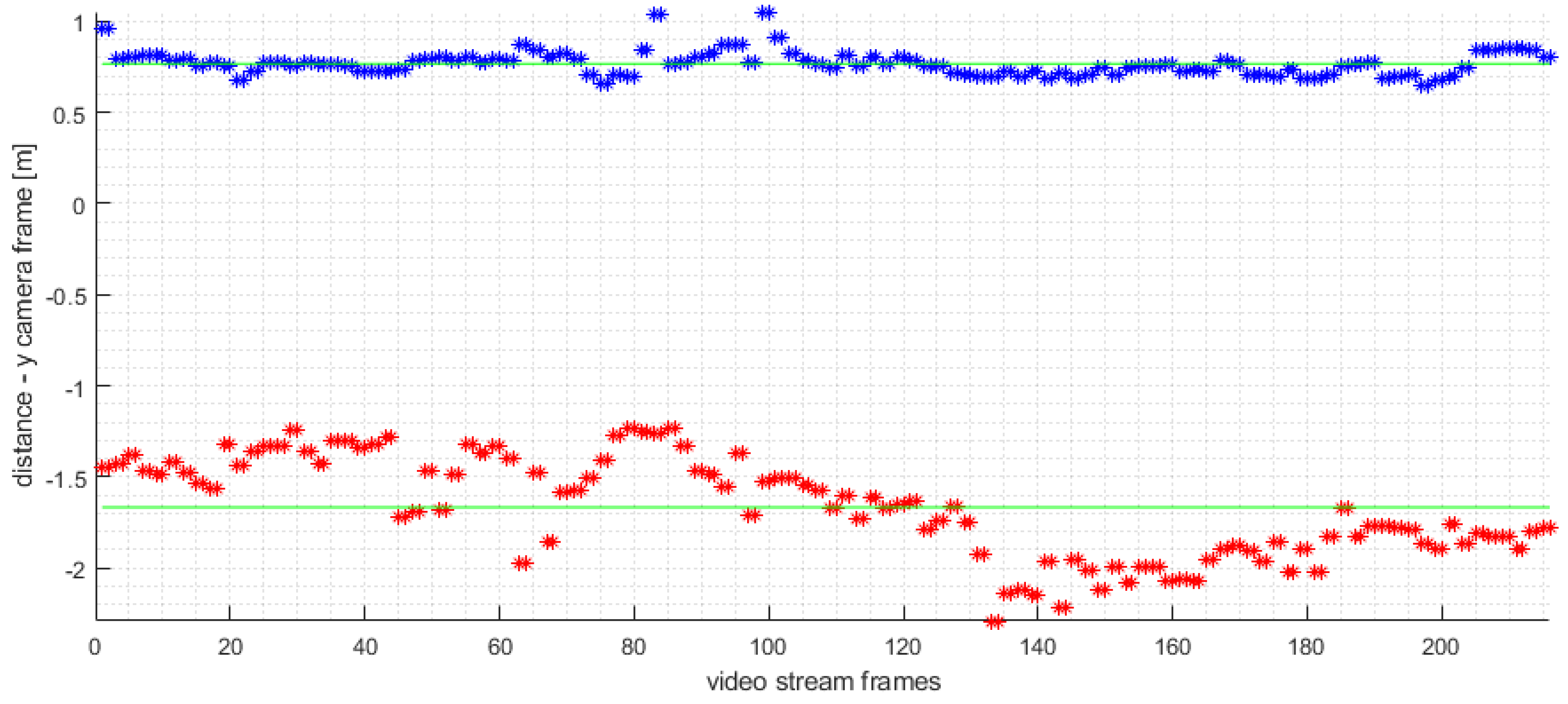
On average, the neural network used was able to detect 5.7 vine trunks in the left row and 5.9 on the right side of the aisle. It follows that a vine trunk can be detected at a distance of up to 12 m. After this distance, detection is sparse, and the influence of image resolution is evident. A best-fit straight line was placed through the estimated vine locations, and the perpendicular distance from the camera to the line was calculated. The given distances for each observed image are shown in Figure 14. It can also be noticed that vines detected on the left side of the aisle are located much more consistently. The consistently more accurate detection of vines on the left-hand side of the aisle can be attributed to the orientation of the camera and its proximity to the left side of the aisle.
We manually evaluated the performance of our proposed method for vine trunk recognition on a video. We counted the number of correctly detected vines, false positive and false negative vines (non-localized vines), and wrongly recognized vines. We defined wrongly recognized vines as trunks that were either recognized twice or belonged to the neighboring row. The results of our analysis are presented in the Table 2. Therefore, the success rate, defined as ratio of correctly and all recognized vine trunks, is .
Vine Trunk Detection as a Goal Setting Method
We wanted to explore the possibility of setting a navigation target based on the recognized vine trunk. In many agricultural areas, all tasks can be accomplished by passing orchids without stopping next to each plant. There is no need to distinguish individual plants. Plants can be grouped together, and all tasks are performed continuously. However, in vineyards, the robot has to position itself next to each vine.
The presented method for point-to-point navigation amidst the rows of a vineyard is based on the visual recognition of vine trunks and odometry of the mobile manipulator. However, in the vineyard with very rough, rocky soil, as seen in Figure 9, odometry becomes much less accurate, and localization consequently deteriorates. Therefore, we introduced a LiDAR to alleviate the problem. The proposed method itself does not require a LiDAR, but for environmental reasons, a LiDAR was added as an additional sensor.
The proposed method for vine trunk localization was experimentally checked in the Jazbina vineyard. A goal was given based on the closest left hand side vine trunk visible in the image. A goal was given in a way that the ATMR-VIV positioned its camera in line with the vine trunk. In Figure 15, the final position of the robot is seen.
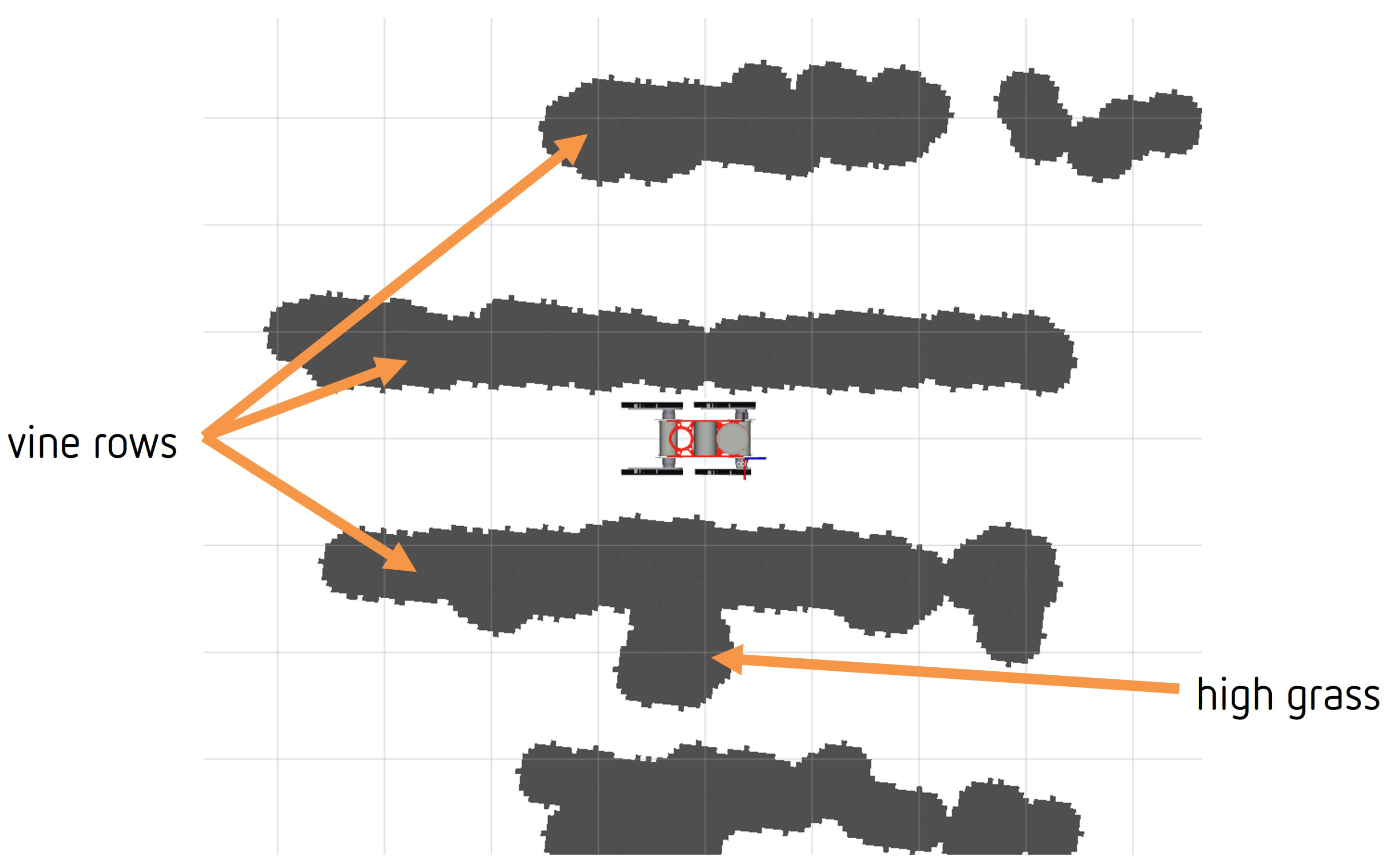
The navigation of ATMR-VIV is based on the principle of local object approach. The goal is set, and the robot uses move_base motion planning to navigate to the desired target pose in the 2D map, while avoiding obstacles. To achieve this, the robot needs a 2D cost map, which we create from a 3D LiDAR scan. In Figure 16, the readings of the sensors during the experiment are shown. The 3D LiDAR point cloud is filtered by height to capture only points in the LiDAR plane and ensure that only relevant information is used to build the cost map. Relatively tall grass does not affect vine growth and is common in vineyards. Therefore, 3D point cloud points below the lower threshold are filtered out to avoid classifying tall grass as an obstacle. However, the terrain in vineyards is uneven, and ground points that are far from the robot can be incorrectly classified as obstacles. The “smaller” cost map was created using only odometry and laser scanning, as shown in Figure 17. By doing so, the terrain’s unevenness was taken into account, and the ground points that were far from the robot were less likely to be classified as obstacles, thus mitigating the problem of uneven terrain. Therefore, our experimental setup used only data from RGB camera, odometry, and laser scan.
To determine the position of the vine, the robot was positioned in an aisle, and we used the method described previously. After detecting the vine, we set a goal next to it, and the robot moved towards it until it reached the goal. However, the robot’s camera only faces forward, and its field of view is not very wide. As a result, the detected trunk soon moves out of the camera’s view. We conducted a couple of subsequent tests on the same terrain, and in each run, the robot was able to successfully detect and localize a vine trunk, set a navigation target, and navigate to the selected vine trunk. A video of the experiment is available at https://youtu.be/Hs-xjM84tiA (accessed on 16 March 2023) and in shown in Supplementary Material: Video S1.
Based on our experimental results, we can conclude that the assumption of the vine trunk height of the vines described in this article is sufficient to determine the positions of vine trunks in the vicinity of the robot.
The demonstrated position of the robot provides the bases for future work on the autonomous execution of the envisaged tasks of autonomous suckering and spraying.
Our future work will focus on improving autonomous navigation. However, during experimental verification, we found a problem with the laser sensors detecting tall grass. Localization will be improved by creating a 2D map of the environment and localizing a robot in this map.
To solve the problem of the laser sensors being obstructed by tall grass during autonomous navigation, we plan to create a map only on the vine trunks detected by the neural network. In this way, we hope to improve the accuracy of our autonomous navigation system and ensure that it can safely navigate through areas with tall grass. There is also room for improvement, in terms of speed.
On the other hand, in future work, we will integrate autonomous suckering, spraying, and removing bark, with autonomous navigation through the entire vineyard (of about 1 hectare).
5. Conclusions
In this paper, we presented the development of localization for the HEKTOR project, enabling it to perform tasks autonomously. Our research focused on the localization of objects of interest in the semi-structured vineyard environment near the mobile manipulator. We used simple assumptions to compute the positions of the vine trunks, relative to the camera, assuming that the height of the detected object corresponds to the height of the first line of the vineyard, a constant parameter in vineyards.
The proposed solution was tested in a real vineyard on a small slope. It has been shown that the assumption of the vine height can be used for the calculation of the position of the vines from single RGB camera.
Our study demonstrates the viability of using a single camera on a robot for autonomous navigation in a vineyard. In addition, all calculations were performed only on the central processing unit of the robot’s on-board computer. Moreover, the robot performed the tasks without being connected to any computer network. This advancement could transform the agricultural industry and make autonomous farming more accessible and affordable for farmers worldwide.
Supplementary Materials
The following supporting information can be downloaded at: https://0-www-mdpi-com.brum.beds.ac.uk/article/10.3390/machines11040414/s1, Video S1: Localization of Mobile Manipulator in Vineyards for Autonomous Task Execution—experiment.
Author Contributions
Conceptualization, I.H. and Z.K.; methodology, I.H. and Z.K.; software, I.H.; validation, I.H.; formal analysis, I.H.; investigation, I.H.; resources, I.H.; data curation, I.H.; writing—original draft preparation, I.H. and Z.K.; writing—review and editing, Z.K.; visualization, I.H.; supervision, Z.K.; project administration, Z.K.; funding acquisition, Z.K. All authors have read and agreed to the published version of the manuscript.
Funding
The research work presented in this article has been supported by the project Heterogeneous autonomous robotic system in viticulture and mariculture (HEKTOR), financed by the European Union, through the European Regional Development Fund—The Competitiveness and Cohesion Operational Programme (KK.01.1.1.04.0036).
Institutional Review Board Statement
Not applicable.
Data Availability Statement
The data that support the findings of this study are available on request from the corresponding author.
Conflicts of Interest
The authors declare no conflict of interest.
References
- Oliveira, L.F.; Moreira, A.P.; Silva, M.F. Advances in agriculture robotics: A state-of-the-art review and challenges ahead. Robotics 2021, 10, 52. [Google Scholar] [CrossRef]
- Gonzalez-de Santos, P.; Fernández, R.; Sepúlveda, D.; Navas, E.; Emmi, L.; Armada, M. Field robots for intelligent farms—Inhering features from industry. Agronomy 2020, 10, 1638. [Google Scholar] [CrossRef]
- Duckett, T.; Pearson, S.; Blackmore, S.; Grieve, B.; Chen, W.H.; Cielniak, G.; Cleaversmith, J.; Dai, J.; Davis, S.; Fox, C.; et al. Agricultural robotics: The future of robotic agriculture. arXiv 2018, arXiv:1806.06762. [Google Scholar] [CrossRef]
- Roure, F.; Bascetta, L.; Soler, M.; Matteucci, M.; Faconti, D.; Gonzalez, J.P.; Serrano, D. Lessons Learned in Vineyard Monitoring and Protection from a Ground Autonomous Vehicle. In Advances in Robotics Research: From Lab to Market; Springer: Berlin/Heidelberg, Germany, 2020; pp. 81–105. [Google Scholar] [CrossRef]
- Dos Santos, F.N.; Sobreira, H.; Campos, D.; Morais, R.; Paulo Moreira, A.; Contente, O. Towards a reliable robot for steep slope vineyards monitoring. J. Intell. Robot. Syst. 2016, 83, 429–444. [Google Scholar] [CrossRef]
- Miller, G.T.; Spoolman, S. Sustaining the Earth; Cengage Learning: Boston, MA, USA, 2014. [Google Scholar]
- Goricanec, J. Heterogeneous autonomous robotic system in viticulture and mariculture-project overview. In Proceedings of the 2021 16th International Conference on Telecommunications (ConTEL), Zagreb, Croatia, 30 June–2 July 2021; pp. 181–188. [Google Scholar] [CrossRef]
- Kapetanović, N.; Goričanec, J.; Vatavuk, I.; Hrabar, I.; Stuhne, D.; Vasiljević, G.; Kovačić, Z.; Mišković, N.; Antolović, N.; Anić, M.; et al. Heterogeneous Autonomous Robotic System in Viticulture and Mariculture: Vehicles Development and Systems Integration. Sensors 2022, 22, 2961. [Google Scholar] [CrossRef] [PubMed]
- Stuhne, D.; Vatavuk, I.; Hrabar, I.; Vasiljević, G.; Kovačić, Z. Automated Suckering of Vines with a Mobile Robot and a Torque-controlled Suckering Tool. In Proceedings of the 2022 International Conference on Smart Systems and Technologies (SST), Macau, China, 30–31 December 2022; pp. 349–354. [Google Scholar] [CrossRef]
- Vatavuk, I.; Stuhne, D.; Vasiljević, G.; Kovačić, Z. Direct Drive Brush-Shaped Tool with Torque Sensing Capability for Compliant Robotic Vine Suckering. Sensors 2023, 23, 1195. [Google Scholar] [CrossRef] [PubMed]
- Vatavuk, I.; Vasiljević, G.; Kovačić, Z. Task Space Model Predictive Control for Vineyard Spraying with a Mobile Manipulator. Agriculture 2022, 12, 381. [Google Scholar] [CrossRef]
- Hrabar, I.; Goričanec, J.; Kovačić, Z. Towards Autonomous Navigation of a Mobile Robot in a Steep Slope Vineyard. In Proceedings of the 2021 44th International Convention on Information, Communication and Electronic Technology (MIPRO), Opatija, Croatia, 27 September–1 October 2021; pp. 1119–1124. [Google Scholar] [CrossRef]
- Hrabar, I.; Vasiljević, G.; Kovačić, Z. Estimation of the Energy Consumption of an All-Terrain Mobile Manipulator for Operations in Steep Vineyards. Electronics 2022, 11, 217. [Google Scholar] [CrossRef]
- Santos, L.; Santos, F.N.; Magalhães, S.; Costa, P.; Reis, R. Path planning approach with the extraction of topological maps from occupancy grid maps in steep slope vineyards. In Proceedings of the 2019 IEEE International Conference on Autonomous Robot Systems and Competitions (ICARSC), Gondomar, Porto, 24–29 April 2019; pp. 1–7. [Google Scholar] [CrossRef]
- Roure, F.; Moreno, G.; Soler, M.; Faconti, D.; Serrano, D.; Astolfi, P.; Bardaro, G.; Gabrielli, A.; Bascetta, L.; Matteucci, M. GRAPE: Ground robot for vineyard monitoring and protection. In Proceedings of the Iberian Robotics Conference, Sevilla, Spain, 22–24 November 2018; Springer: Berlin/Heidelberg, Germany, 2018; pp. 249–260. [Google Scholar] [CrossRef]
- Ravankar, A.; Ravankar, A.A.; Rawankar, A.; Hoshino, Y. Autonomous and safe navigation of mobile robots in vineyard with smooth collision avoidance. Agriculture 2021, 11, 954. [Google Scholar] [CrossRef]
- Astolfi, P.; Gabrielli, A.; Bascetta, L.; Matteucci, M. Vineyard autonomous navigation in the echord++ grape experiment. IFAC-PapersOnLine 2018, 51, 704–709. [Google Scholar] [CrossRef]
- Hroob, I.; Polvara, R.; Molina, S.; Cielniak, G.; Hanheide, M. Benchmark of visual and 3D lidar SLAM systems in simulation environment for vineyards. In Proceedings of the Annual Conference Towards Autonomous Robotic Systems, Lincoln, UK, 8–10 September 2021; Springer: Berlin/Heidelberg, Germany, 2021; pp. 168–177. [Google Scholar] [CrossRef]
- Ahmadi, A.; Nardi, L.; Chebrolu, N.; Stachniss, C. Visual servoing-based navigation for monitoring row-crop fields. In Proceedings of the 2020 IEEE International Conference on Robotics and Automation (ICRA), Paris, France, 31 May–31 August 2020; pp. 4920–4926. [Google Scholar] [CrossRef]
- Vit, A.; Shani, G. Comparing rgb-d sensors for close range outdoor agricultural phenotyping. Sensors 2018, 18, 4413. [Google Scholar] [CrossRef] [PubMed] [Green Version]
- Condotta, I.C.; Brown-Brandl, T.M.; Pitla, S.K.; Stinn, J.P.; Silva-Miranda, K.O. Evaluation of low-cost depth cameras for agricultural applications. Comput. Electron. Agric. 2020, 173, 105394. [Google Scholar] [CrossRef]
- Aghi, D.; Cerrato, S.; Mazzia, V.; Chiaberge, M. Deep semantic segmentation at the edge for autonomous navigation in vineyard rows. In Proceedings of the 2021 IEEE/RSJ International Conference on Intelligent Robots and Systems (IROS), Prague, Czech Republic, 27 September–1 October 2021; pp. 3421–3428. [Google Scholar] [CrossRef]
- Aguiar, A.S.; Monteiro, N.N.; Santos, F.N.d.; Solteiro Pires, E.J.; Silva, D.; Sousa, A.J.; Boaventura-Cunha, J. Bringing semantics to the vineyard: An approach on deep learning-based vine trunk detection. Agriculture 2021, 11, 131. [Google Scholar] [CrossRef]
- de Aguiar, A.S.P.; dos Santos, F.B.N.; dos Santos, L.C.F.; de Jesus Filipe, V.M.; de Sousa, A.J.M. Vineyard trunk detection using deep learning–An experimental device benchmark. Comput. Electron. Agric. 2020, 175, 105535. [Google Scholar] [CrossRef]
- Santos, L.C.; Aguiar, A.S.; Santos, F.N.; Valente, A.; Ventura, J.B.; Sousa, A.J. Navigation stack for robots working in steep slope vineyard. In Proceedings of the SAI Intelligent Systems Conference, London, UK, 3–4 September 2020; Springer: Berlin/Heidelberg, Germany, 2020; pp. 264–285. [Google Scholar] [CrossRef]
- Sarmento, J.; Aguiar, A.S.; Santos, F.N.d.; Sousa, A.J. Robot navigation in vineyards based on the visual vanish point concept. In Proceedings of the 2021 International Symposium of Asian Control Association on Intelligent Robotics and Industrial Automation (IRIA), Goa, India, 20–22 September 2021; pp. 406–413. [Google Scholar] [CrossRef]
- Badeka, E.; Kalampokas, T.; Vrochidou, E.; Tziridis, K.; Papakostas, G.; Pachidis, T.; Kaburlasos, V. Real-time vineyard trunk detection for a grapes harvesting robot via deep learning. In Proceedings of the Thirteenth International Conference on Machine Vision, Rome, Italy, 8–12 November 2021; Volume 11605, pp. 394–400. [Google Scholar] [CrossRef]
- Martini, M.; Cerrato, S.; Salvetti, F.; Angarano, S.; Chiaberge, M. Position-Agnostic Autonomous Navigation in Vineyards with Deep Reinforcement Learning. In Proceedings of the 2022 IEEE 18th International Conference on Automation Science and Engineering (CASE), Mexico City, Mexico, 22–26 August 2022; pp. 477–484. [Google Scholar] [CrossRef]
- Van Dijk, T.; De Croon, G. How Do Neural Networks See Depth in Single Images? In Proceedings of the 2019 IEEE/CVF International Conference on Computer Vision (ICCV), Seoul, Korea, 27 October–2 November 2019; pp. 2183–2191. [Google Scholar] [CrossRef] [Green Version]
- Jocher, G. YOLOv5 by Ultralytics. 2020. Available online: https://0-doi-org.brum.beds.ac.uk/10.5281/zenodo.3908559 (accessed on 16 March 2022).
- VineSet. Available online: http://vcriis01.inesctec.pt/datasets/DataSet/VineSet.zip (accessed on 8 February 2022).
- Humain-Lab-Vine-Trunk-Dataset. Available online: https://github.com/humain-lab/vine-trunk (accessed on 5 April 2022).
- Tzutalin. Labellmg. Available online: https://github.com/heartexlabs/labelImg (accessed on 7 March 2022).
Figure 1.
The section of the vineyard chosen to carry out the experiments is indicated in orange in the Jazbina vineyard. In this work, the experiments were carried out in the aisle marked in blue. The Jazbina vineyard is located on an 8% slope with clayey soil.
Figure 1.
The section of the vineyard chosen to carry out the experiments is indicated in orange in the Jazbina vineyard. In this work, the experiments were carried out in the aisle marked in blue. The Jazbina vineyard is located on an 8% slope with clayey soil.

Figure 2.
Design of an all-terrain mobile manipulator (ATMM-VIV) driven by four independently controlled flippers/tracks in two possible configurations. (a) Robotic tool with one degree of freedom (shaft rotation). (b) The 7 DoF robot arm with brush.
Figure 2.
Design of an all-terrain mobile manipulator (ATMM-VIV) driven by four independently controlled flippers/tracks in two possible configurations. (a) Robotic tool with one degree of freedom (shaft rotation). (b) The 7 DoF robot arm with brush.

Figure 3.
Schematic overview of the navigation operation of a heterogeneous HEKTOR viticulture robot system. Global planning provides ATMM-VIV the entry points into the aisles (marked with blue circle). Planning and navigation through the aisles is based on local features: vine trunks.
Figure 3.
Schematic overview of the navigation operation of a heterogeneous HEKTOR viticulture robot system. Global planning provides ATMM-VIV the entry points into the aisles (marked with blue circle). Planning and navigation through the aisles is based on local features: vine trunks.

Figure 4.
A sketch of robot navigation through the aisle. Example of a vineyard aisle setup with three positions of the robot and the field of view of the camera. When navigating through a vineyard, a row of vines may be outside the field of view. In case (a), only one side of the aisle is visible. In case (b), both sides are in the field of view. In case (c), only one vine trunk is in the robot’s field of view because of the end of the aisle. The centerline of the robot’s field of view is also a tangent to the path. The positions of the vine trunks are marked with a red dot.

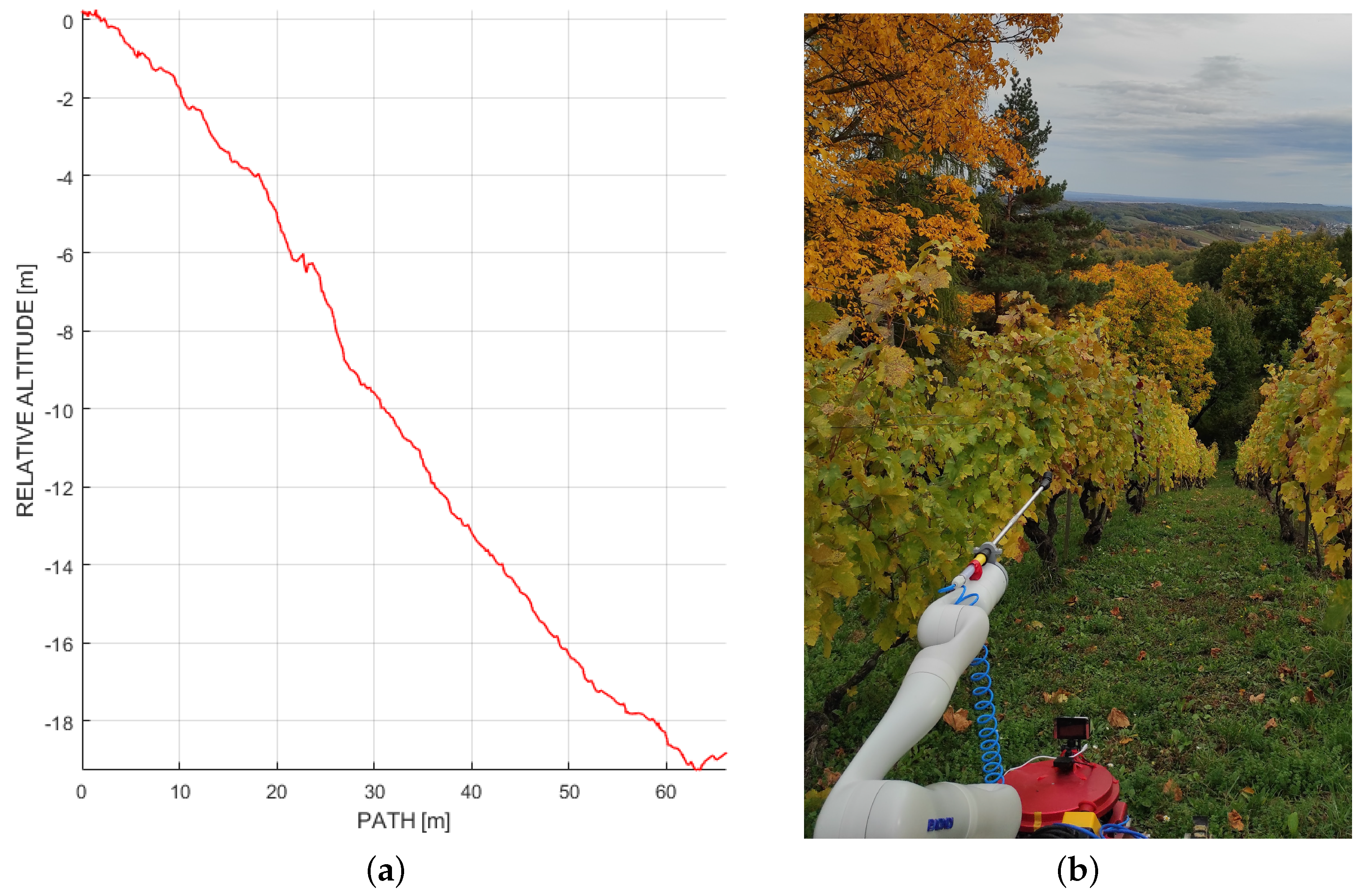
Figure 5.
An example of a steep slope vineyard used for previous work and described in [13]. One can see the influence of the slope on the field of view of the robot. The vineyard shown has a slope of up to 54%. (a) A cross-section of the vineyard. (b) An image of ATMM-VIV at the beginning of the aisle.

Figure 6.
Schematic overview of the three possible cases of the navigation process with positions of ATMM-VIV, in relation to the vine trunks in the aisle. The positions of the vine trunks are marked with a red dot. In case (a), the robot navigates through the center of the aisle. This case is suitable for a surveillance task. In case (b), the robot navigates continuously near the vines, which is required for the spraying task. In case (c), the robot also navigates from point to point (marked with red cross) in the immediate vicinity of the vines to ensure that the trunk of the vines is within the working range of the robot arm, which is a necessary condition for the suckering task.

Figure 7.
High-level task flow of vine trunk-based navigation for autonomous vineyard task execution. After entering a new aisle, the ATMM positions itself next to the next vine trunk in the aisle. The robot performs the desired task and moves to the next vine trunk. At the end of the aisle, the robot moves to the next aisle. The process is repeated until the mission is completed.

Figure 8.
Height assumption to locate a vine trunk near the ATMM-VIV. Assuming the actual height of the identified feature in the image allows localization of the position of the observed object, relative to the camera.
Figure 8.
Height assumption to locate a vine trunk near the ATMM-VIV. Assuming the actual height of the identified feature in the image allows localization of the position of the observed object, relative to the camera.

Figure 9.
Example of vine trunk detection in a vineyard on rocky terrain in Lubarda, an example of a soil composition usually found in regions with karstic geological topography.
Figure 9.
Example of vine trunk detection in a vineyard on rocky terrain in Lubarda, an example of a soil composition usually found in regions with karstic geological topography.

Figure 10.
True and apparent object size and position in camera frame and image coordinates.

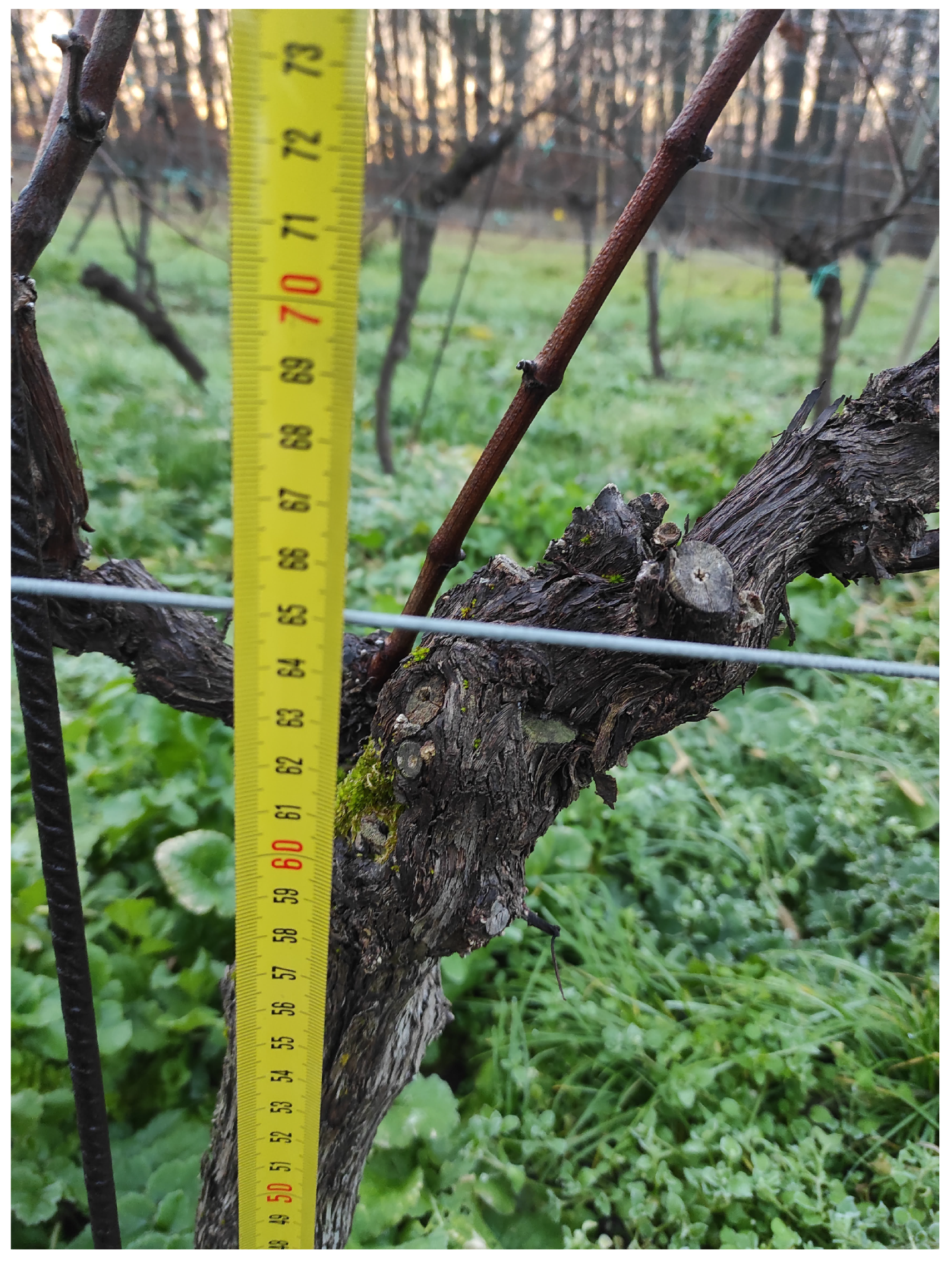
Figure 11.
A section of the vine where the trunk of the vine begins to divide into two stems. The fork is located in the vineyards at the level of the first wire. In this case (vineyard Jazbina), it is located at a height of 65 cm above the ground.
Figure 11.
A section of the vine where the trunk of the vine begins to divide into two stems. The fork is located in the vineyards at the level of the first wire. In this case (vineyard Jazbina), it is located at a height of 65 cm above the ground.

Figure 12.
An image input for the detection and the estimated positions of the vine trunks around the ATMM-VIV. The red arrow is the desired goal position for the robot to perform the given task. (a) Animage input for the detection. (b) Estimated positions.
Figure 12.
An image input for the detection and the estimated positions of the vine trunks around the ATMM-VIV. The red arrow is the desired goal position for the robot to perform the given task. (a) Animage input for the detection. (b) Estimated positions.

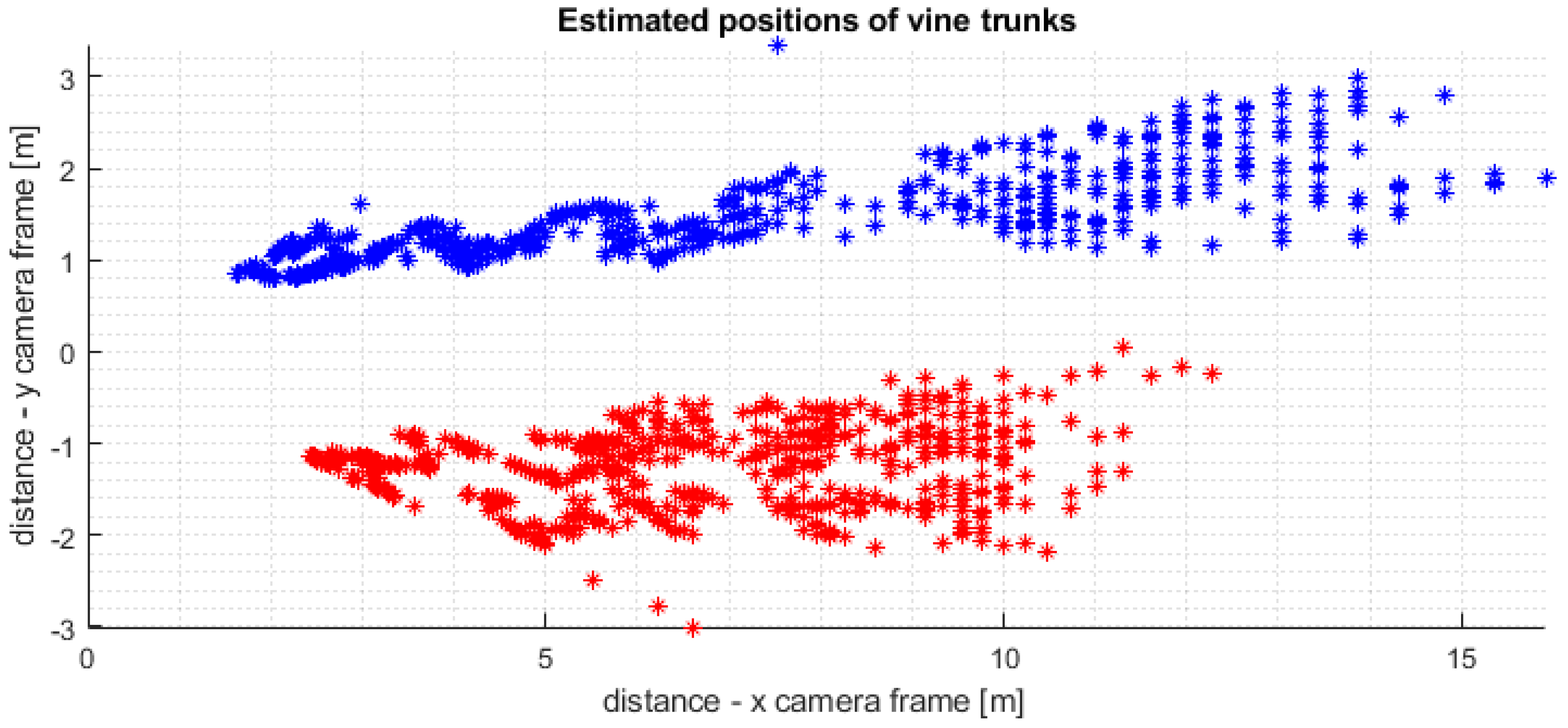
Figure 13.
The figure shows the superposition of all detected vine locations in the observed aisle in the optical frame of the camera. This overlay was created by determining the location of the first left vine trunk (blue) from each image, resulting in a total of 2494 vine trunk locations. Of these, 1226 (blue) are from the left side of the aisle, while 1268 are from the other side (red). In the upper part of the image, the outliner of a detected vine trunk can be seen, which is the result of detecting a vine trunk in the next aisle.

Figure 14.
Estimated horizontal distance of the camera from the vines on the left (blue) and right (red) sides.
Figure 14.
Estimated horizontal distance of the camera from the vines on the left (blue) and right (red) sides.

Figure 15.
Position of the ATMR-VIV after reaching the specified goal next to the detected vine.

Figure 16.
An experimental setup for autonomous navigation to the recognized vine in a vineyard environment, visualized in Rviz. This visualization uses data that has been acquired during the experimental campaign in Jazbina vineyard. The robot’s perception of the environment at the beginning of the experiment is shown. The position of the detected vine is marked with the red cylinder. The red arrow is the goal pose of the robot. The goal pose is located in the immediate vicinity of the detected vine. In the goal pose, the distance between the vine and the robot should be smaller than .

Figure 17.
The 2D costmap generated from the 3D point cloud, used for the move_base package.


Table 1.
Hyperparameters used for neural network training.
| Parameter | Comment | Value |
|---|---|---|
| image HSV-hue augmentation | fraction | 0.15 |
| image HSV-saturation augmentation | fraction | 0.7 |
| image HSV-value augmentation | fraction | 0.4 |
| image rotation | +/− deg | 15.0 |
| image translation | +/− fraction | 0.1 |
| image scale | +/− gain | 0.5 |
| image shear | +/− deg | 0.0 |
| image perspective | +/− fraction | 0.0001 |
| image flip up-down | probability | 0.0 |
| image flip left-right | probability | 0.5 |
| image mosaic | probability | 0.0 |
| image mixup | probability | 0.0 |
| segment copy-paste | probability | 0.0 |
Table 2.
Performance of the proposed method.
| Correct | False Positive | False Negative | Double Detection | Neighboring Row |
|---|---|---|---|---|
| 298 | 14 | 16 | 14 | 1 |
Disclaimer/Publisher’s Note: The statements, opinions and data contained in all publications are solely those of the individual author(s) and contributor(s) and not of MDPI and/or the editor(s). MDPI and/or the editor(s) disclaim responsibility for any injury to people or property resulting from any ideas, methods, instructions or products referred to in the content. |
© 2023 by the authors. Licensee MDPI, Basel, Switzerland. This article is an open access article distributed under the terms and conditions of the Creative Commons Attribution (CC BY) license (https://creativecommons.org/licenses/by/4.0/).
Share and Cite
MDPI and ACS Style
Hrabar, I.; Kovačić, Z. Localization of Mobile Manipulator in Vineyards for Autonomous Task Execution. Machines 2023, 11, 414. https://0-doi-org.brum.beds.ac.uk/10.3390/machines11040414
AMA Style
Hrabar I, Kovačić Z. Localization of Mobile Manipulator in Vineyards for Autonomous Task Execution. Machines. 2023; 11(4):414. https://0-doi-org.brum.beds.ac.uk/10.3390/machines11040414
Chicago/Turabian StyleHrabar, Ivan, and Zdenko Kovačić. 2023. "Localization of Mobile Manipulator in Vineyards for Autonomous Task Execution" Machines 11, no. 4: 414. https://0-doi-org.brum.beds.ac.uk/10.3390/machines11040414
Note that from the first issue of 2016, this journal uses article numbers instead of page numbers. See further details here.