Article

Novel Design of Variable Stiffness Pneumatic Flexible Shaft Coupling: Determining the Mathematical-Physical Model and Potential Benefits

Faculty of Mechanical Engineering, Technical University of Košice, Letná 1/9, 042 00 Košice-Sever, Slovakia
*
Author to whom correspondence should be addressed.
Submission received: 1 December 2023 / Revised: 26 December 2023 / Accepted: 29 December 2023 / Published: 31 December 2023
(This article belongs to the Special Issue Research on Rotor Dynamics and Vibration Control)

Abstract

:
Presently, mechanical system vibroisolation is becoming increasingly important. One of the new approaches is semi-active vibroisolation using elements capable of changing a selected mechanical property. These include, among others, pneumatic flexible shaft couplings capable of changing torsional stiffness during operation. The main goal of the article is to examine the potential advantages of a newly patented pneumatic coupling over a current type with the same pneumatic element arrangement. For comparison, parameters determinable from static load characteristics were selected. These parameters are maximum twist angle and torque, average torsional stiffness, and the percentage of torque transmitted by the bellows rubber shell. In all cases, the new coupling had better properties. Since the prototype of the new coupling has not yet been produced, its parameters were determined from its mathematical-physical model. The article contains a full procedure to obtain the static load characteristic of a new coupling type, beginning with the determination of air bellows force/height and volume/height characteristics, then optimum sizes of coupling with regards to the operating range of elements, the dependency of element height on the coupling’s twist angle, and finally the computation of the static load characteristic considering isothermal gas compression. The presented procedure can be applied to any pneumatic bellows where the force/height characteristics of different pressures are given.

1. Introduction

Presently, minimizing the vibration and noise of mechanical system drives has become increasingly important and demanding [1,2]. The entire issue is very extensive and includes aspects such as safety and lifetime of machines [3,4,5,6,7,8,9] and protection of workers against noise and vibration [10,11]. In the field of piston combustion engines, as a source of vibration, emphasis is placed on improving their efficiency and reducing emissions [12,13,14].
In mechanical drives, there is often excessive torsional oscillation caused mainly by reciprocating machines such as combustion engines and compressors, where by constant speed of shaft the transmitted torque is periodic [15,16,17]. But even in drive systems with electric motors, excessive torsional oscillations can occur, especially during transient conditions such as start-up and braking [16,18,19,20].
One of the most common and easiest ways to deal with problems associated with torsional vibration is to use a suitable flexible shaft coupling [15,21]. In addition to the transmission of the torque itself, flexible shaft couplings not only enable smaller misalignments of the connected shafts but mainly dampen torsional shocks and can reduce the amplitude of torsional oscillations [1,21]. By a suitable flexible coupling, we mean a coupling with suitable mechanical properties. From the point of view of the transmission of periodic torque, the most important mechanical property of the coupling is its torsional stiffness [15,16,22]. Torsional stiffness of coupling is a parameter that affects the value of the natural frequency of the whole mechanical system. And if this natural frequency is equal to one of the frequencies of the harmonic components of the exciting moment, then the mechanical system is in resonance [16]. Theoretically, if there was no damping in the mechanical system, the amplitude of torque could grow to infinity in the state of resonance. But even with damping, the dependence of the torsional amplitude on operating speed in the state of resonance reaches a maximum, which can cause increased stress and consequently damage to drive components [23]. Flexible couplings are advantageous because if we can choose a coupling with suitable torsional stiffness, we can avoid resonance, at least in a certain range of operating speeds. This adaptation of the natural frequency is also called tuning of the mechanical system [21].
From a design point of view, commonly produced flexible couplings use rubber, metal, or plastic flexible elements. During operation, these elements change their mechanical properties due to temperature, aging, and wear [24,25,26]. This mainly concerns flexible elements made of rubber and plastic. With such elements, over time, the mechanical system becomes “out of tune”. For the sake of completeness, it is necessary to mention that tuning can be achieved not only by changing the torsional stiffness but also by changing the damping or mass moments of inertia and also by using additional devices as dampers, absorbers, and eliminators of torsional vibration [1,2,15,27]. However, all these methods achieve the tuning of the mechanical system for specific operating conditions (or range of operating conditions) by setting the mechanical parameters (stiffness, damping, mass-moment of inertia) in advance during the design process, provided that these parameters then remain unchanged. Such methods, using elements whose properties cannot be changed during operation (elements using no additional energy), are usually referred to as passive vibroisolation [28].
Nowadays, modern trends such as operating at a wide range of speeds and cylinders with uneven operation (different fuel supply in each cylinder, cylinder deactivation) aimed at reducing emissions and increasing efficiency make the tuning of mechanical systems from the point of view of torsional oscillation increasingly difficult [1]. Selecting a suitable standard flexible coupling for such a range of operating conditions may be almost impossible. For example, in marine and reciprocating compressor applications, barred speed ranges are used to avoid resonance [29,30]. As passive vibroisolators, couplings specially designed for specific mechanical systems may be used [31,32]. Because of these problems, elements of so-called semi-active vibroisolation are gradually beginning to develop. These are elements whose selected mechanical properties can be changed during operation [28].
Among the elements capable of changing torsional stiffness designed for use in mechanical drives, pneumatic flexible shaft couplings [21,33], couplings with magnetorheological elastomers [34,35,36], magnetic shaft couplings [37,38,39,40], and also couplings with variable active length leaf springs [41,42,43] can be mentioned.
Similar principles, but in the field of robotics, are used for the design of joints and actuators of variable stiffness [44]. In this case, the main goal is to ensure safety and shock absorption in an environment where collisions with humans or another object are possible. Here we can also mention devices using magnets [45], springs preloaded by cam mechanisms [46,47], cable mechanisms [48,49,50,51], or devices using variable active length leaf springs [51,52].
However, variable stiffness and semi-active vibroisolation are developed not only for elements with torsional loads but also for suspension of rectilinearly oscillating masses in driver’s seats [53,54], base mounts of industrial machinery [55], and vehicles [56].
Our workplace focuses on the research, development, and utilization of methods of pneumatic flexible shaft couplings. Pneumatic flexible shaft coupling uses compressed gas as a means of flexible torque transmission. As a gaseous medium, mostly air is used, but experiments were also made with helium and propane/butane [57]. According to several patents [58,59,60], compressed air can be enclosed in standard or special air bellows, air hoses, or cylinders with pistons, and various mechanisms are used for changing their volume. Pneumatic flexible shaft couplings are usable as elements of semi-active torsional vibroisolation, as we can change their torsional stiffness during operation by changing the gas pressure. Another advantage of using compressed gas as a flexible element is that it is not subject to aging. For ensuring semi-active vibroisolation, several methods were proposed, of which the most significant and most experimentally tested are autoregulation at a constant twist angle [61] and extremal control [62,63].
The main goal of this article is to explore the potential benefits of a new type of pneumatic flexible shaft coupling patented under the name “tangential pneumatic flexible shaft coupling with axially deformed flexible elements” [64,65] over a classic tangential pneumatic flexible shaft coupling using the same arrangement of the same type of flexible elements (air bellows). The selected parameters, which can be determined from the static characteristics (maximum twist angle, maximum torque, static torsional stiffness, and percentage of torque transmitted by the element’s rubber shell), were compared. In all the mentioned parameters, the new coupling shows better properties. Since the prototype of the new coupling has not yet been produced, its parameters were determined from its mathematical-physical model. The article contains the full procedure to obtain the static load characteristics of the new coupling type, starting with the determination of element force/height and volume/height mathematical dependencies, selecting optimum coupling design parameters (dimensions) considering the deformation range of elements given by the manufacturer’s datasheet, determining the element height/twist angle formula of the coupling, and finally computing the static load characteristic’s considering isothermal compression. The presented procedure can be used for any pneumatic element (bellows), where the force/height characteristics of different pressures are given by the manufacturer.

2. Materials and Methods

2.1. Brief Characteristics of the Examined Types of Pneumatic Flexible Shaft Couplings

One of the currently used types of pneumatic flexible shaft couplings is the so-called tangential pneumatic flexible shaft coupling. In Figure 1a, a 4–2/70–T–C-type tangential pneumatic flexible shaft coupling is shown [66,67]. The type of designation indicates that the coupling uses four double bellows pneumatic elements with a diameter of 70 mm placed tangentially with fully interconnected compression spaces. Between the discs of coupling (1), pneumatic bellows springs (2) are used as flexible elements. This coupling uses NORGREN PM/31022 [68,69] pneumatic elements. The flanges of elements are attached to V-shape consoles (3) and immovably connected to the coupling’s discs. The compression spaces of pneumatic elements are interconnected with hoses (4). When the coupling is loaded with torque, one pair of elements (in the opposite position) is compressed and the other is stretched.
The experimental setup during static measurement is shown in Figure 1b. The coupling (1) is loaded via arm (2) with jack (3). The twist angle is measured with index and scale (4) and the static torque with torque measuring cell (5). The compressed air is fed into the coupling from the compressor (6), and the air overpressure is measured with the pressure sensor (7). Experiments were made with different initial overpressures; the coupling was gradually loaded, and the dependencies of torque and overpressure on twist angle were measured. A detailed description of measurements can be found in [68].
Even though it is a thoroughly researched and proven design [66,67,68], we decided to improve it even further. As it is clear from the coupling’s design, when the coupling is twisted, not only the elements are compressed and stretched in the axial direction, but they are also bended. This reduces the range of axial deformation (when measured between the centers of flanges). Furthermore, due to the absence of manufacturer’s data on the load characteristic of the bent elements [69], it is impossible to determine the load characteristic of the whole coupling by calculation, so it must be measured on the manufactured prototype of the coupling. To obtain a complete mathematical-physical model of static load characteristics, torque and pressure dependencies on twist angle must be measured at different initial overpressures. The complete procedure is described in [70].
Therefore, a new design with rotatable mounted consoles ensuring only axial deformation of elements has been developed. The new type of coupling was patented under the name “tangential pneumatic flexible shaft coupling with axially deformed flexible elements” [64,65]. This coupling is shown in Figure 2a in the neutral position and in Figure 2b at the maximum twist angle.
The coupling consists of a driving (1) and a driven hub (2) with flexible connections ensured via pneumatic bellows springs as flexible elements (3). Pneumatic elements are attached to V-shaped support bodies (4). The support bodies (4) are mounted on pins (5), which ensures the possibility of their rotation and maintaining the parallel position of the element’s flanges to the full extent of the twist angle (Figure 3). This makes it possible to fully utilize the pneumatic element’s stroke given by its manufacturer. Another significant advantage of this coupling is that we can determine its load characteristics by calculation using the load characteristics given in the datasheet of the pneumatic element manufacturer.
Although the coupling shown in Figure 2 has six flexible elements compared to the coupling in Figure 1, it is practically possible to use any even number of flexible members.
In order to verify the potential advantages of “tangential pneumatic flexible shaft coupling with axially deformed flexible elements” (for simplicity, hereafter referred to only as “new coupling”) over the current “tangential pneumatic flexible shaft coupling” (further referred to as “classic coupling”), we decided to create a mathematical model of the load characteristics of the new coupling with identical arrangements of elements in neutral position as one of the classic coupling prototypes with known properties [66,67,68]. And then compare the computed properties of the new coupling with the measured properties of the classic coupling. For this purpose, the previously presented 4–2/70–T–C type tangential pneumatic flexible shaft coupling, shown in Figure 1, was selected.

2.2. Determining the Mathematical Model of Tangential Pneumatic Flexible Shaft Coupling with Axially Deformed Flexible Elements

2.2.1. Determining the Mathematical Model of Pneumatic Element Force

The procedure to determine the mathematical-physical model of an element’s force characteristics is similar to the method described in article [70] for the static load characteristics of pneumatic couplings.
It is necessary to first know the deformation range and load characteristics of its flexible elements. These data are given in the element’s manufacturer datasheet [69]. The deformation range of the used pneumatic elements (NORGREN PM/31022) is shown in Figure 3.
where:
  • he
  • heA = 65 mm
  • heB = 105 mm
  • heC = 110 mm
  • αop,max = 10°
  • is the height of element in general;
  • minimum installation height;
  • maximum working height;
  • maximum installation height;
  • maximum operating angle.
The datasheet further states that the application of elements in a limit range between heB and heC has to be consulted with the manufacturer.
In the datasheet, the force of element F [N] (there named as thrust) by overpressures 2, 4, 6, and 8 bar and the volume of element Ve [l] by 6-bar overpressure depending on the height of element he [mm] (there named as stroke) are presented in the form of a graph.
The graph from the datasheet was exported to image format and used as a background image in the workspace of a graphic program (AutoCAD). Then the courses were redrawn from the background, and their values for selected element heights were measured. The obtained values are presented in Figure 4.
The force of pneumatic flexible element F [N] is a sum of two forces: the deformation force of the rubber shell FG [N] (further referred to as “gum force”) and thew pressure force of gas volume enclosed inside the rubber shell FV [N] (further referred to as “volumetric force”):
F = F G + F V
The pressure inside the pneumatic element p [Pa] consists of atmospheric pressure pa, where pa = 105 Pa was considered, and overpressure pp [Pa]:
p = p a + p p
Distinguishing between absolute pressure and overpressure is very important in terms of the gas compression (or expansion) process, which may be isothermal, adiabatic, or polytrophic.
During the axial deformation of an element, the work performed by volumetric force FV [N] on displacement dhe [m] (change of element height) is equal to the value of the work of compressed gas with overpressure pp [Pa] with the corresponding volume change dVe [m3]:
F V · d h e = p p · d V e
Now we can define the effective area of the pneumatic element Se [m2] as:
S e = d V e d h e
Then, substituting it into Equation (3), the volumetric force can be computed as:
F V = p p · S e
Finally, by substituting Equation (5) into Equation (1), we obtain a formula for computing the force of an element:
F = F G + p p · S e
For simplicity, we assume that the gum force FG and effective area of the pneumatic element Se depends only on the height of the pneumatic element he [m]:
F = F G ( h e ) + p p · S e ( h e )
The next task is to determine the functions of the gum of force F G ( h e ) and effective area of the element S e ( h e ) depending on its height. As we can see in Equation (7), for a constant height he, the dependence of force F on overpressure pp is linear. Therefore, we need to express the dependence of force F on overpressure pp by constant heights he. For the force values F by each height of the element he, a linear regression has been computed (Figure 5). The coefficient of determination R2 for these regression formulas is at least 0.9991, so the match between the manufacturer’s datasheet and the calculated values is very good.
The linear term of the regression formulas in Figure 5 represents the effective area Se [m2], and the constant term, the intersection of the regression line with the vertical axis, represents the gum force FG [N] by the corresponding constant element height he [mm].
The values of gum force FG are shown in Figure 6, and the values of effective area Se are shown in Figure 7.
Now, using regression, we can express the formulas for the gum force FG [N] (in Figure 6) depending on element height he [m] as:
F G = 2.341 · 10 6 · h e 3 + 6.124 · 10 5 · h e 2 5.741 · 10 4 · h e + 1.920 · 10 5 ,
and the effective area of pneumatic element Se [m2] (in Figure 7) depending on element height he [m] as:
S e = 6.094 · h e 3 2.276 · h e 2 + 0.1863 · h e 1.072 · 10 3  
The volume of pneumatic element Ve [m3], as follows from Formula (4), can be calculated by integrating Se (Formula (9)):
V e = 1.726 · h e 4 0.7587 · h e 3 + 9.315 · 10 2 · h e 2 1.072 · 10 3 · h e 7.279 · 10 5
The constant term of the formula has been optimized to obtain the minimum sum of squares of the differences between the computed volume Ve and the values given by the manufacturer’s datasheet (Figure 4). A comparison of the computed volume (Equation (10)) and the datasheet values (Figure 4) is shown in Figure 8. The coefficient of determination between the two datasets is R2 = 0.9998.
The comparison, in the form of percentage difference δF [%] = (FcompFdata)/Fdata × 100, between the force of the element computed according to Formula (7) (Fcomp) and datasheet values (Fdata—according to Figure 4) is shown in Figure 9. The biggest differences can be seen for the maximum height of elements and lower pressures, and the maximum difference is smaller than 4%. The coefficient of determination R2 = 0.99996 too shows very good agreement of our mathematical model with values given by the manufacturer.

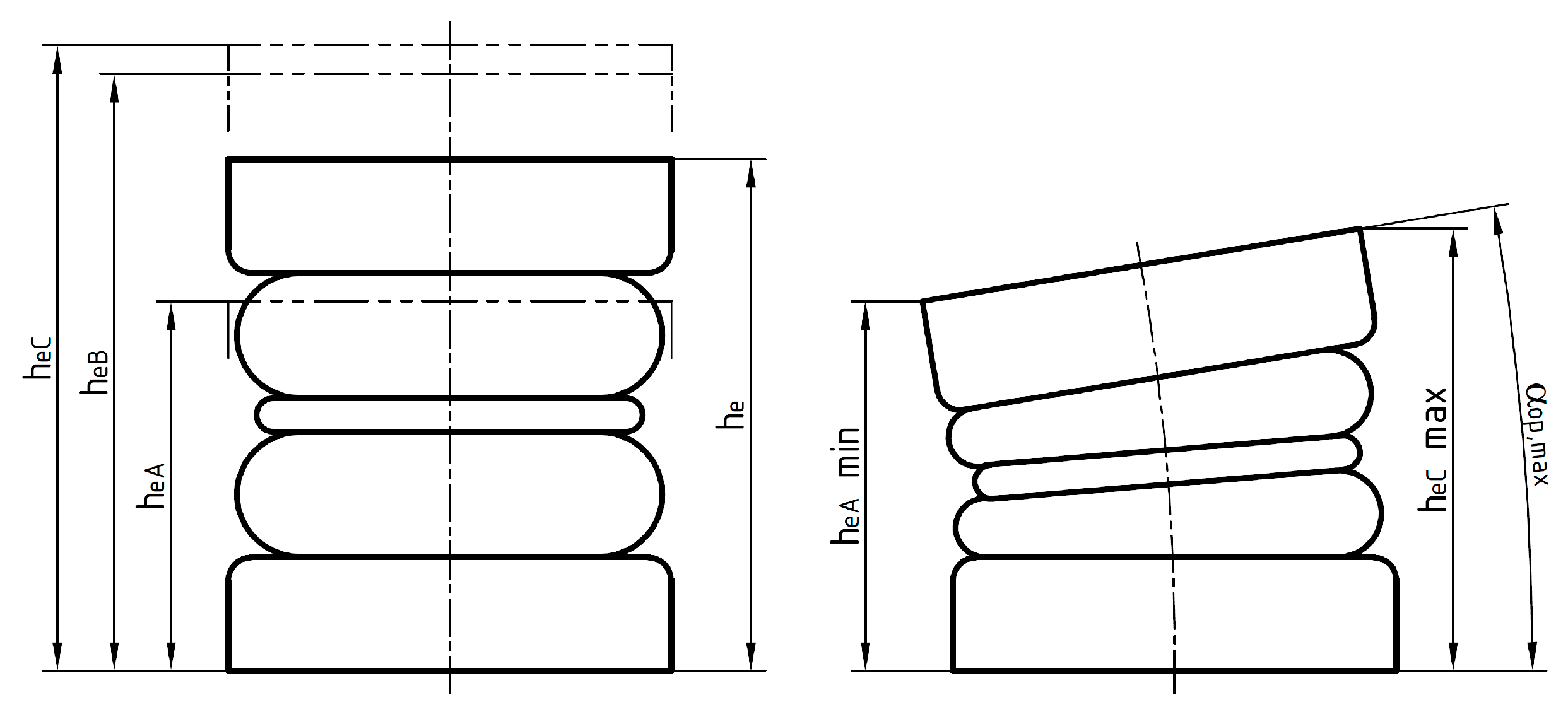
2.2.2. Geometry of Coupling—Kinematics and Determination of the Optimum Parameters

The geometry of tangential pneumatic flexible shaft coupling with i (i must be an even number) axially deformed flexible elements is shown in Figure 10. Figure 10a shows one pair of coupling’s segments in neutral position, together with v-supports and pneumatic elements. Figure 10b shows the pins of the same coupling by twist angle φ.
where:
  • hv
  • he
  • hen
  • h
  • hn
  • hc
  • hs
  • αv
  • αn
  • αc
  • αs
  • e
  • en
  • ec
  • es
  • a
  • R
  • Fc
  • Fs
  • is the height of a V-shaped support, further referred to as v-height;
  • height of the element in general;
  • height of the element in the coupling’s neutral position;
  • height of the segment in general;
  • height of the segment in the coupling’s neutral position;
  • height of the compressed segment;
  • height of the stretched segment;
  • angle of v-support, further referred to as v-angle;
  • neutral angle between pins is equal to the neutral angle of the segments;
  • angle of the compressed segment;
  • angle of stretched segment;
  • eccentricity of the pneumatic element in general;
  • eccentricity of the pneumatic element in neutral position;
  • eccentricity of a compressed pneumatic element;
  • eccentricity of a stretched pneumatic element;
  • distance between two adjacent pins located on the same flange;
  • pitch radius of pins;
  • force of a compressed pneumatic element;
  • force of a stretched pneumatic element.
One of the aims of this article is to compute the static load characteristics of coupling when the volume change is very slow and the compression process of gas enclosed inside the element can be considered isothermal.
The whole recommended procedure for computing and selecting the sizes of couplings is based on the geometry shown in Figure 10. First, we have to select the number of pneumatic elements i, which has to be an even number.
In neutral position, the segments of coupling are equally spaced; thus, the neutral angle of the pins is:
α n = 2 π i
The support surfaces of pneumatic elements have to be parallel, so the v-angle must be equal to the neutral angle of the pins:
α v = α n
Generally, the v-height can be selected arbitrarily. From a practical point of view, it is advantageous to use small support bodies to obtain a compact coupling with a small diameter, a high twist angle, and low torsional stiffness. The minimum v-height is limited by mounting options resulting from the v-angle, sizes of support bodies (pin hub diameter, support flange thickness), installation dimensions of pneumatic elements (flange diameter, thread diameters, arrangement of threaded holes), and the dimensions of selected mounting screws. On the other hand, a larger coupling diameter allows for higher torque, but at the cost of a lower twist angle and higher torsional stiffness.
The distance between the centers of two adjacent pins, referred to as the height of segment h, is computed as:
h = h e + 2 · h v
According to Figure 10b, the distance between two adjacent pins located on the same flange a can be determined at the maximum twist angle φmax from the corresponding extreme height of segments hc = hmin, hs = hmax, and the v-angle αv using the cosine theorem as follows:
a = h m i n 2 + h m a x 2 + 2 · h m i n · h m a x · cos ( α v ) ,
Then values of hmin and hmax, should respect the permissible values given by the manufacturer of pneumatic elements. If we want to fully utilize the stroke of pneumatic elements, at maximum twist angle φmax, the compressed element should have the minimum permissible height he = heA and the stretched element the maximum permissible height he = heC (or heB). Then the optimum value of a can be determined as:
a o p t = A 2 + B 2 + 2 · A · B · cos ( α v ) ,
where the minimum permissible segment height hmin = A = heA + 2·hv and the maximum permissible segment height hmax = B = heC + 2·hv (or B = heB + 2·hv).
Then, the optimum pitch radius is as follows:
R o p t = a o p t 2 · sin ( α n )
The real (selected) value of pitch radius R should be close to the optimum value Ropt. Of course, we can select a (little bit) different value due to reasons such as having the value of R an integer number or standard size, but for obtaining a coupling with a different size (diameter), it is much better to change the v-height, use a different pneumatic element, or use a different number of pneumatic elements.
Then we can determine the maximum angle of the segment corresponding to height B when hmax = B:
α m a x B = 2 · a r c s i n B 2 R   ,
The minimum angle of the segment corresponding to height A, when hmin = A:
α m i n A = 2 · a r c s i n A 2 R   .
Then, if R = Ropt, then the strokes of both the compressed and stretched elements are fully utilized. The maximum twist angle of the coupling is:
φ m a x = α m a x B α m i n A 2
If R < Ropt, then the radius of coupling is smaller than optimum, and the heights of elements will be shorter (imagine in Figure 10a lowering R with all the other independent parameters unchanged), so the maximum twist angle is computed from the minimum segment height, angle αminA, as follows:
φ m a x = α n α m i n A
If R > Ropt, then the radius of coupling is larger than optimum, and the heights of elements will be higher, so the maximum twist angle is computed from the maximum segment height, angle αmaxB, as follows:
φ m a x = α m a x B α n

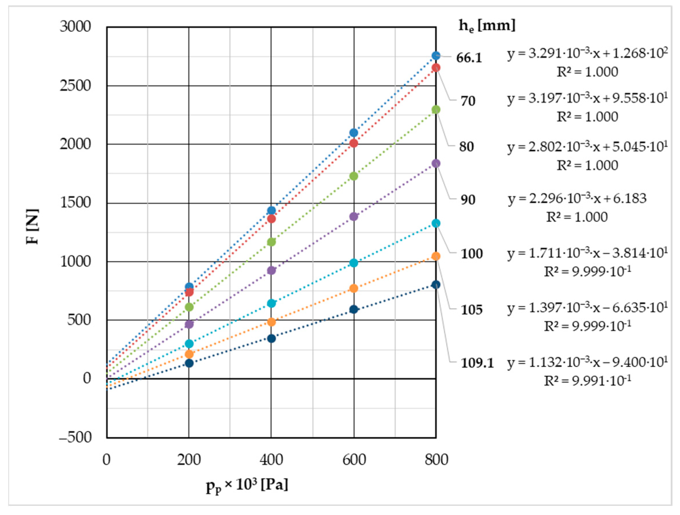
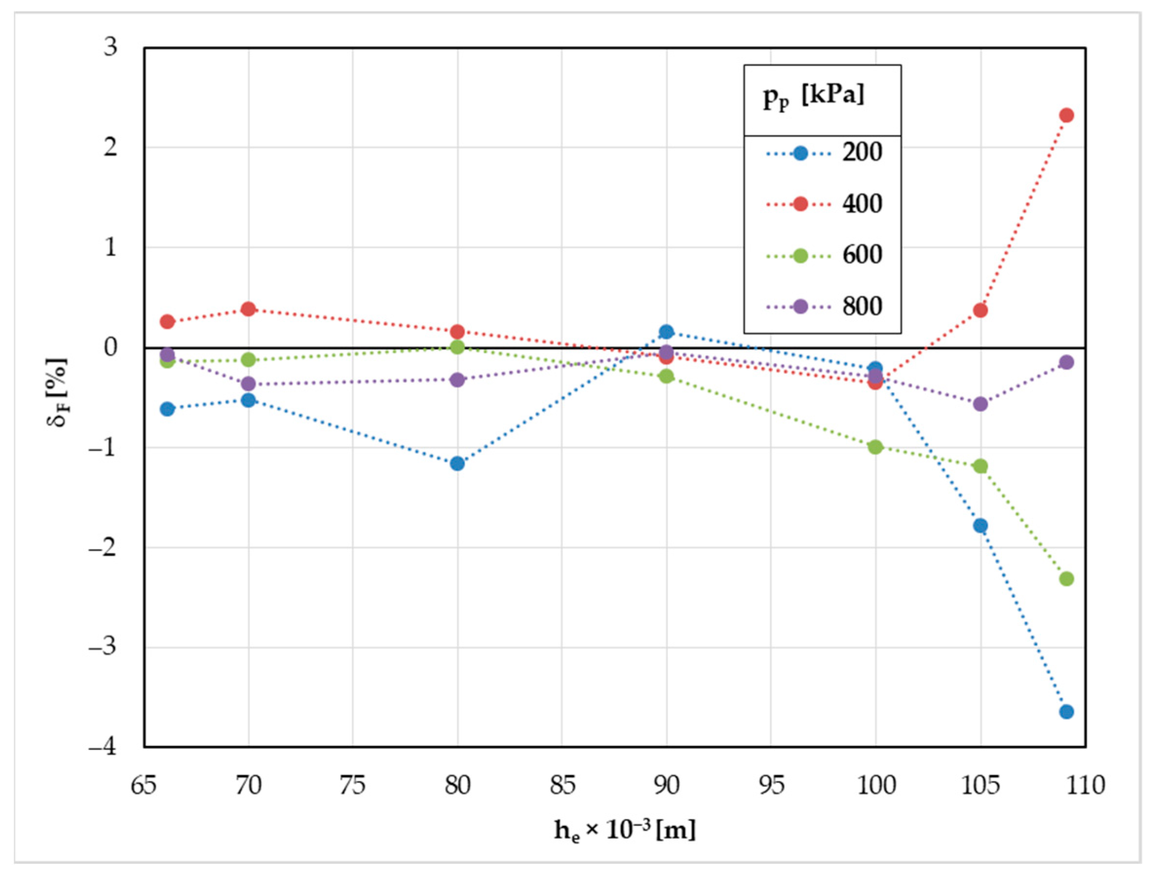
2.2.3. Computation of Static Load Characteristics

The computation of static load torque characteristics is based on the geometry of the coupling shown in Figure 10 and the mathematical model of pneumatic element force described in Section 2.2.1.
The torque transmitted by coupling T [N·m] is a sum of torques derived by forces of both compressed and stretched pneumatic elements, Fc and Fs [N], acting on arms equal to eccentricities ec and es [m]:
T = i 2 · F c · e c + F s · e s
To determine the eccentricities ec and es, we need to know the angles of compressed and stretched segments, αc and αs [rad], which are calculated from the neutral pin angle αn [rad] and twist angle φ [rad] as:
α c , s = α n φ
According to this equation, the minimum and maximum pin angles corresponding to the maximum twist angle φmax are:
α m i n , m a x = α n φ m a x
Then the eccentricities of compressed and stretched pneumatic elements, ec and es [m], are:
e c , s = R · c o s α c , s 2
To compute the forces of pneumatic elements, Fc and Fs, we need to know the heights, volumes, and effective areas of elements, as well as the overpressure in their compression volumes.
The heights of compressed and stretched segments, hc and hs [m], can be computed as follows:
h c , s = 2 · R · s i n α c , s 2
The minimum and maximum height of pneumatic elements corresponding to the maximum twist angle φmax according to Formula (26) are equal to:
h m i n , m a x = 2 · R · s i n α m i n , m a x 2
Then the heights of compressed and stretched elements hec and hes [m] are as follows:
h e   c , s = h c , s 2 · h v
Volumes of compressed and stretched elements are computed according to Equation (10) using the corresponding heights of elements, Vec = Ve(hec) and Ves = Ve (hes) [m3].
There are two basic options regarding the connection of pneumatic element compression volumes:
(a)
The compression volumes of all compressed and stretched pneumatic elements are connected, forming a common compression volume where the pressure in all compressed and stretched elements, considering the static (slow) torsional deformation of the coupling, is the same.
(b)
The compression volumes of compressed and stretched elements are separated, so the pressure in compressed and stretched elements is different. Generally, we assume that in the neutral position of coupling, the segments are equally spaced and the initial pressure on all elements is the same. It is possible to pressurize both groups of elements differently, but in this case the actual neutral position of coupling (by zero transmitted torque) would be different (segments not equally spaced), and the load characteristics in one direction of twist angle will not be the same as in the opposite direction.
Further in this article, we consider only the case of common compression volume.
The forces of compressed and stretched elements are computed using Formula (7) as follows:
F c , s = F G   c , s + p p · S e   c , s
where:
  • F G   c , s [N] is the gum force of compressed and stretched elements according to Formula (8).
  • pp [Pa] is the overpressure in the common compression volume of the coupling.
  • S e   c , s [m2] is the effective area of compressed and stretched elements according to Formula (9).
Considering the slow torsional deformation of the coupling, where the temperature of the compressed gas has enough time to equalize with the ambient temperature, the gas compression process can be considered isothermal. The actual pressure in the compression volume p [Pa] at twist angle φ is then:
p = p 0 · V 0 V
where p0 [Pa] and V0 [m3] are the initial values of pressure and compression volume in the neutral position of coupling by zero twist angle and zero transmitted torque, and V [m3] is the actual compression volume at twist angle φ.
The compression volume is then:
V = i 2 · V e c + V e s + V a d d
where Vadd [m3] is the additional volume connected to the compression volume of the pneumatic elements (volumes of gas supply hoses, interconnecting hoses, etc.).

3. Results and Discussion

3.1. Geometric Design and Comparison of Maximum Twist Angle and Torsional Stiffness

As mentioned before, to determine the potential advantages of the new coupling design over the classic one, we selected the 4–2/70–T–C type tangential couplings whose characteristics were already known from previous measurements [66,67,68]. The coupling uses four PM/31022 pneumatic elements, and their arrangement in neutral position at zero angle is shown in Figure 11a.
The maximum twist angle φmax = 9.43° of this coupling was determined by a graphical solution; see Figure 11b. The maximum twist angle, as we can see in Figure 11b, is limited by the minimum permissible height, heA = 65 mm, given in the manufacturer’s datasheet. The maximum height of element hemax = 108.8 mm is 1.2 mm less than the maximum permissible height heC = 110 mm, and the maximum operation angle of element equal to the maximum twist angle of coupling φmax = 9.43° is 0.57° smaller than the permissible operating angle αop,max = 10°. It would be optimal if all these values were equal to the permissible ones, but from the given values, we can conclude that the parameters of the real coupling are very close to optimum.
The proposed design of the new coupling uses the same arrangement of elements in neutral position as the given classic coupling. The arrangement of pneumatic elements at the maximum twist angle is shown in Figure 11c. For determining the maximum twist angle, we can use equations 15–21. The maximum twist angle is now φmax = 12.909°, which is 1.37 times higher than the maximum twist angle of the classic coupling. As for the classic coupling with the same element arrangement in neutral position, the limiting parameter for twist angle is the minimum height of the element, hemin = heA = 65 mm. The maximum height of the element hemax = 107.6 mm is 2.4 mm less than the maximum permissible height heC = 110 mm. As the rotatable mounting of v-supports allows to maintain the parallel position of element flanges, the maximum twist angle of coupling is not limited by the maximum operation angle of the pneumatic element αop,max = 10°.
Just for the sake of interest, we also mention that the ideal value of pitch radius, given v-height and permissible heights of elements, according to Equation (16), is Ropt = 134.9 mm, which is 0.9 mm more than the used value. And the resulting maximum twist angle is then φmax = 13.542°, which is 0.633° more than the actual value.

3.2. Comparison of Static Load Characteristics, Maximum Load Torque, and Torsional Stiffness

The measured static characteristics of classic coupling by different initial overpressures pp0 = (100, 200, …, 700) kPa are shown in Figure 12a. The measurements of the static characteristics were carried out up to the angle where there was no change in the nature of the curve [68]. The maximum angle reached was 11 degrees, exceeding the maximum deformation range of the elements given by the manufacturer. However, we must remember that such an angle was used only for the purpose of experimentally determining the static load characteristic.
The maximum angle resulting from the limitations given by the manufacturer of flexible elements is marked in the figure as φmax. Hence, if we refer to the maximum torque of the classic coupling later in the article, then torque at angle φmax = 9.43° is considered. Figure 12a also shows the rubber torque TG determined by using the mathematical model of the coupling described in more detail in works [66,67,68].
The static characteristics of new coupling by different overpressures pp0 = (0, 100, …, 700) kPa and gum torque TG were computed according to Formulas (22)–(31). In Formula (31), additional volume additional volume Vadd = 4.37·10−5 m3 was used. This value is the same as for the classic coupling as described in [66].
The resulting static load characteristics are shown in Figure 12b. It is obvious at first glance that the new coupling can transfer more torque at the maximum overpressure of pp0 = 700 kPa. To get a clearer idea of the transmission capacity of both couplings, the value of the maximum torque Tmax achieved at the maximum twist angle φmax and the ratio of these torques are shown in Figure 13a. The maximum torque of classic coupling at twist angle φmax = 9.43 ° was determined by the method of linear interpolation between two adjacent measured values (from Figure 12a). The ratio of maximum torques between the new and classic couplings varies in the range of 0.984 to 1.322. From the above, we can conclude that the new coupling is not only able to transmit about 32% larger torque (at overpressure pp0 = 700 kPa), but also has a larger control range. This is very advantageous, especially if we want to use the coupling as a semi-active torsional vibration tuner.
Another very important parameter in terms of torsional vibration tuning is the torsional stiffness of the coupling, which affects the natural torsional frequency of the mechanical system where the coupling is applied [16]. It is generally better to have a coupling with lower torsional stiffness. Lower torsional stiffness allows us to obtain lower natural torsional frequencies, and thus we have a greater chance that the system will work in the so-called supercritical area [21]. As we can see in Figure 12, the static load characteristics of both pneumatic couplings are slightly nonlinear and progressive [21].
For the purpose of this article (a mutual comparison of coupling mechanical properties), the average torsional stiffness ke was determined for each initial overpressure (Figure 13b). The value of ke is computed as equivalent constant stiffness with the same area under the curve (from zero to maximum twist angle) as the actual load characteristics. The torsional stiffness of new coupling in the examined range of initial overpressure is always smaller than the torsional stiffness of classic coupling. Specifically, the ratio of ke between classic and new couplings varies approximately in the range of 1.45 to 1.05, depending on the initial overpressure.
If we compute the average torsional stiffness of the element’s rubber shell keG (average gum stiffness) from the torques TG in Figure 12, we obtain the following values:
  • keG = 7.2 Nm·°−1 for classic coupling.
  • keG = 3.1 Nm·°−1 for new coupling.
The average gum stiffness keG of the classic coupling is about 2.3 times higher than that of the new coupling, even though the arrangement of pneumatic elements in neutral position is the same. This is most likely due to the additional bending of pneumatic elements when the coupling is twisted (see Figure 11).

3.3. Comparison of the Gum Torque Effect

Another very interesting parameter of pneumatic flexible shaft couplings is the effect of gum torque TG on the total torque T. In general, it can be said that the impact of the rubber shell itself on the coupling’s torque should be as small as possible. This results from the fact that rubber gradually changes its properties due to aging and temperature [24,25,26], but the effect of air depends only on its pressure. Of course, the air pressure also depends on its temperature, but the temperature of the pneumatic elements increases only slightly even with high twist angle amplitudes [24]. And if the design of the drive makes it possible to change the air pressure in the coupling during operation, we can set it to a suitable value at any time as needed.
For the classic coupling, the percentage of gum torque TG to total torque T depending on twist angle φ for different overpressures pp0 is shown in Figure 14a. The percentage of gum torque varies from about 65% at initial overpressure pp0 = 100 kPa to about 20% at initial pressure pp0 = 700 kPa.
For the new coupling, the percentage of gum torque TG to total torque T depending on twist angle φ for different overpressures pp0 is shown in Figure 14b. The percentage of gum torque varies from about 40% at initial overpressure pp0 = 100 kPa to about 10% at initial pressure pp0 = 700 kPa. For the sake of interest, in Figure 14b, we have also included the value of gum torque percentage at zero initial overpressure, which varies from 100% at zero twist angle to about 90% at maximum twist angle.
In both cases, we can see that the influence of the rubber, depending on the twist angle, is not constant. On the other hand, it does not change dramatically. Therefore, we decided to express the average value of the gum torque percentage from minimum to maximum twist angle for each overpressure and then compare them for both couplings. The comparison is shown in Figure 15, where we can see the average gum torque percentage values depending on initial overpressure and also the ratio between these average percentages (classic coupling vs. new coupling).
From Figure 15, we can conclude that the influence of gum torque on the classic coupling is, especially at higher pressures, several times greater than that of the new coupling. Specifically, this value varies in the range of roughly 1.7–2.4. Hence, in this last investigated parameter too, the new coupling shows better properties than the classic one.

4. Conclusions

From the above results, we can conclude that the new coupling has better properties than the classic coupling in all the investigated parameters. It has about 1.4 times higher maximum twist angle, 1.3 times higher maximum torque by initial overpressure (700 kPa), 1.45 to 1.05 times lower average torsional stiffness depending on initial overpressure, and 1.7–2.4 times lower gum torque percentage depending on initial overpressure. The great advantage of the new coupling type is that the load characteristic can be calculated from the data of the element’s manufacturer and not just measured on a manufactured prototype.
However, it must be said that the new type also has certain disadvantages compared to the classic one. For example, a more complex design and the presence of a rotary mounting of v-supports will cause friction during cyclic loading. Another problem could be the buckling stability of element assembly, especially when using elements with a large height (double and triple bellows elements). But this issue cannot be simply identified from a mathematical model due to the lack of necessary data (in the element’s datasheet).
In our further research, we plan to make a prototype of tangential pneumatic flexible shaft coupling with axially deformed flexible elements and verify the correctness of the presented mathematical model by comparing it with measured values. We would also like to determine, in addition to the static properties, the dynamic properties such as dynamic torsional stiffness and damping.

5. Patents

Kaššay, P.; Grega, R. Tangential pneumatic flexible shaft coupling with axially deformed flexible elements. Patent SK 288875 B6, Industrial Property Office of the Slovak Republic, Banská Bystrica 2021 (14 July 2021). Available online: https://wbr.indprop.gov.sk/WebRegistre/Patent/Detail/78-2017? (accessed on 27 October 2023) (In Slovak).

Author Contributions

Conceptualization, P.K. and R.G.; methodology, P.K., M.U. and J.K.; software, P.K.; validation, P.K. and M.U.; formal analysis, P.K.; investigation, M.U. and J.K.; resources, M.U.; data curation, P.K.; writing—original draft preparation, P.K.; writing—review and editing, L.Ž.; visualization, P.K., J.K., M.K. and L.Ž.; supervision, R.G.; project administration, R.G.; funding acquisition, R.G. All authors have read and agreed to the published version of the manuscript.

Funding

This paper was written within the framework of the VEGA 1/0528/20 grant project “Solution of new elements for mechanical system tuning”.

Data Availability Statement

Data are contained within the article.

Conflicts of Interest

The authors declare no conflicts of interest.

References

  1. Zoul, V. Dynamic of propulsion, present situation and trends. Trans. Univ. Košice 2014, 2, 101–106. [Google Scholar]
  2. Liang, X.; Shu, G.; Dong, L.; Wang, B.; Yang, K. Progress and Recent Trends in Torsional Vibration of Internal Combustion Engines. In Advances in Vibration Analysis Research; Ebrahimi, F., Ed.; InTech: Rijeka, Croatia, 2011; pp. 245–272. [Google Scholar] [CrossRef]
  3. Wojnar, G.; Czech, P.; Folęga, P. Problem with Diagnosing Local Faults of Gearboxes on the Basis of Vibration Signal. Trans. Univ. Košice 2014, 95–100. [Google Scholar]
  4. Białek, P.; Bielawski, P.J. Failure analysis of refinery hydrogen reciprocating compressors. Diagnostyka 2018, 19, 83–92. [Google Scholar] [CrossRef]
  5. Maláková, S.; Frankovský, P.; Harachová, D.; Neumann, V. Design of Constructional Optimisation Determined for Mixer Truck Gearbox. Ad Alta J. Interdiscip. Res. 2019, 9, 414–417. [Google Scholar]
  6. Marasova, D.; Andrejiova, M.; Grincova, A. Experimental Study of the Influence of the Interaction of a Conveyor Belt Support System on Belt Damage Using Video Analysis. Appl. Sci. 2023, 13, 7935. [Google Scholar] [CrossRef]
  7. Bortnowski, P.; Doroszuk, B.; Krol, R.; Marasova, D.; Moravic, M.; Ozdoba, M. Forecasting Blockades of Conveyor Transfer Points Based on Vibrodiagnostics. Meas. J. Int. Meas. Confed. 2023, 216, 112884. [Google Scholar] [CrossRef]
  8. Šulka, P.; Sapietová, A.; Bárnik, F. Vibrodiagnostics of rolling ball bearings connected with processing, result´s comparison and prediction of service life. Sci. J. Sil. Univ. Tech. 2020, 106, 183–196. [Google Scholar] [CrossRef]
  9. Wojnar, G.; Burdzik, R.; Wieczorek, A.N.; Konieczny, Ł. Multidimensional Data Interpretation of Vibration Signals Registered in Different Locations for System Condition Monitoring of a Three-Stage Gear Transmission Operating under Difficult Conditions. Sensors 2021, 21, 7808. [Google Scholar] [CrossRef]
  10. Moravec, M.; Badida, M.; Mikušová, N.; Sobotová, L.; Švajlenka, J.; Dzuro, T. Proposed options for noise reduction from a wastewater treatment plant: Case study. Sustainability 2021, 13, 2409. [Google Scholar] [CrossRef]
  11. Wandor, M.; Burdzik, R. Research on vibration of steering gear of automotive vehicle. Vibroeng. Procedia 2015, 6, 264–267. [Google Scholar]
  12. Galdo, M.I.L. Marine Engines Performance and Emissions. J. Mar. Sci. Eng. 2021, 9, 280. [Google Scholar] [CrossRef]
  13. Puškár, M.; Jahnátek, A.; Kádárová, J.; Šoltésová, M.; Kovanič, Ľ.; Krivosudská, J. Environmental study focused on the suitability of vehicle certifications using the new European driving cycle (NEDC) with regard to the affair “dieselgate” and the risks of NOx emissions in urban destinations. Air Qual. Atmos. Health 2019, 12, 251–257. [Google Scholar] [CrossRef]
  14. Czech, P. Diagnosing faults in the timing system of a passenger car spark ignition engine using the Bayes classifier and entropy of vibration signals. Sci. J. Sil. Univ. Tech. 2022, 116, 83–98. [Google Scholar] [CrossRef]
  15. Feese, T.; Hill, C. Prevention of Torsional Vibration Problems in Reciprocating Machinery. In Proceedings of the 38th Turbomachinery Symposium, Houston, TX, USA, 14–17 September 2009; Texas A&M University, Turbomachinery Laboratories: College Station, TX, USA, 2018; pp. 213–238. [Google Scholar] [CrossRef]
  16. Wachel, J.C.; Szenasi, F.R. Analysis of Torsional Vibrations in Rotating Machinery. In Proceedings of the Twenty-Second Turbomachinery Symposium, Dallas, TX, USA, 14–16 September 1993; Texas A&M University: College Station, TX, USA, 1993; pp. 127–151. [Google Scholar]
  17. Lu, J.; Zheng, H.; Husnain Haider, M.; Feng, Y.; Zhi, P.; Cheng, J.; Wang, Z. Fracture failure analysis of flywheel hub served in heavy-fuel aviation piston engine. Eng. Fail. Anal. 2023, 151, 107363. [Google Scholar] [CrossRef]
  18. Jackson, C.; Leader, M.E. Design, Testing and Commissioning of a Synchronous Motor-Gear-Axial Compressor. In Proceedings of the 12th Turbomachinery Symposium, College Station, TX, USA, November 1983; Jenkins, P.E., Ed.; Texas A&M University, Turbomachinery Laboratories: College Station, TX, USA, 1983; pp. 97–112. [Google Scholar] [CrossRef]
  19. Adachi, A.; Oba, S. Overcoming Failure of Synchronous Motor Driven Compressor Train by Application of Controlled Slip Clutch; Turbomachinery Laboratory, Texas A&M Engineering Experiment Station: College Station, TX, USA, 2020. [Google Scholar]
  20. Kaššay, P.; Homišin, J.; Urbanský, M.; Grega, R. Transient Torsional Analysis of a Belt Conveyor Drive with Pneumatic Flexible Shaft Coupling. Acta Mech. Autom. 2017, 11, 69–72. [Google Scholar] [CrossRef]
  21. Homišin, J. New Types of Flexible Shaft Couplings: Development, Research, Application; Vienala: Košice, Slovakia, 2002. [Google Scholar]
  22. Zeng, Q.; Bin, G.; Li, C.; Chen, L. Study on the influence of torsional stiffness of coupling on torsional vibration characteristics of slender series shafting of submersible oil electric pump. Chin. J. Eng. Des. 2021, 28, 89–94. [Google Scholar] [CrossRef]
  23. Gorbacovs, D.; Gavrilovs, P.; Eiduks, J.; Strautmanis, G. Failure analysis of rubber-cord couplings of ER2 series electric trains. In Proceedings of the 22nd International Scientific Conference Engineering for Rural Development, Jelgava, Latvia, 24–26 May 2023. [Google Scholar] [CrossRef]
  24. Gurský, P. Influence of working cycles identification on characteristics of flexible couplings and their comparison. Ph.D. Thesis, Technical University of Košice, Košice, Slovakia, 9 March 2011. [Google Scholar]
  25. Homišin, J.; Kaššay, P. Influence of temperature on characteristics properties of flexible coupling. Transp. Probl. 2012, 7, 123–129. [Google Scholar]
  26. Opasiak, T.; Margielewicz, J.; Gąska, D.; Haniszewski, T. Influence of changes in the working temperature of flexible couplings on their stiffness characteristics. Transp. Probl. 2022, 17, 177–186. [Google Scholar] [CrossRef]
  27. Wilson, W.K. Practical Solution of Torsional Vibration Problems, 3rd ed.; Chapman & Hall Ltd.: London, UK, 1969; Volumes 1–5. [Google Scholar]
  28. Bartel, T.; Herold, S.; Infante, F.; Käsgen, J.; Matthias, M.; Millitzer, J.; Perfetto, S. Active Vibration Reduction of Ship Propulsion Systems. In Proceedings of the 2018 Joint Conference—Acoustics, Ustka, Poland, 11–14 September 2018; Polish Acoustical Society: Ustka, Poland, 2018; pp. 15–20. [Google Scholar]
  29. Kim, Y.G.; Hwang, S.J.; Cho, K.H.; Kim, U.K. Characteristics of propulsion shafting system in ships with engine acceleration problems in the barred speed range. Ocean. Eng. 2017, 145, 479–491. [Google Scholar] [CrossRef]
  30. Smooth Compressor Applications—Eliminating Speed Restrictions with Geislinger Technology. Available online: https://www.geislinger.com/en/blog/smooth-compressor-applications-eliminating-speed-restrictions-with-geislinger-technology/ (accessed on 22 November 2023).
  31. Song, L.Q.; Zeng, L.P.; Zhang, S.P.; Zhou, J.D.; Niu, H.E. Design and analysis of a dual mass flywheel with continuously variable stiffness based on compensation principle. Mech. Mach. Theory 2014, 79, 124–140. [Google Scholar] [CrossRef]
  32. Kowal, A.; Filipowicz, K. The construction of metal flexible torsional coupling. Transp. Probl. 2007, 2, 69–76. [Google Scholar]
  33. Nemchinov, S.; Khristenko, A. Stress-strain state of pneumatic flexible shaft coupling for ball mill drives. Sci. J. Silesian Univ. Technol. Ser. Transp. 2018, 99, 125–134. [Google Scholar] [CrossRef]
  34. Behrooz, M.; Wang, X.; Gordaninejad, F. Modeling of a new semi-active/passive magnetorheological elastomer isolator. Smart Mater. Struct. 2014, 23, 045013. [Google Scholar] [CrossRef]
  35. Syam, T.M.I.; Hegazi, A.A.A.; Muthalif, A.G.A.; Badri, Y. Magnetorheological elastomer-based variable stiffness flexible coupling for vibration isolation. Trans. Can. Soc. Mech. Eng. 2021, 46, 1–10. [Google Scholar] [CrossRef]
  36. Lee, K.H.; Park, J.E.; Kim, Y.K. Design of a stiffness variable flexible coupling using magnetorheological elastomer for torsional vibration reduction. J. Intell. Mater. Syst. Struct. 2019, 30, 2212–2221. [Google Scholar] [CrossRef]
  37. Gasparoto, H.F.; Chocron, O.; Benbouzid, M.; Meirelles, P.S. Advances in reconfigurable vectorial thrusters for adaptive underwater robots. J. Mar. Sci. Eng. 2021, 9, 170. [Google Scholar] [CrossRef]
  38. Lubin, T.; Colle, A. Simulation analysis and experimental evaluation of the transient behaviour of a reluctance magnetic coupling. IET Electr. Power Appl. 2020, 14, 391–397. [Google Scholar] [CrossRef]
  39. Sudano, A.; Accoto, D.; Zollo, L.; Guglielmelli, E. Design, development and scaling analysis of a variable stiffness magnetic torsion spring. Int. J. Adv. Robot. Syst. 2013, 10, 372. [Google Scholar] [CrossRef]
  40. Gasparoto, H.F.; Chocron, O.; Benbouzid, M.; Meirelles, P.S. Design of an Optimally Stiff Axial Magnetic Coupling for Compliant Actuators. In Proceedings of the IECON Proceedings (Industrial Electronics Conference), Lisbon, Portugal, 14–17 October 2019; IEEE Computer Society: Washington, DC, USA, 2019; Volume 1, pp. 5198–5203. [Google Scholar]
  41. Kinnunen, K.; Laine, S.; Tiainen, T.; Viitala, R. Method for Adjusting Torsional Natural Frequencies of Powertrains with Novel Coupling Design. Machines 2022, 10, 162. [Google Scholar] [CrossRef]
  42. Kinnunen, K.; Laine, S.; Tiainen, T.; Viitala, R.; Seppänen, A.; Turrin, T.; Kiviluoma, P.; Viitala, R. Coupling with adjustable torsional stiffness. Proc. Est. Acad. Sci. 2021, 70, 470–476. [Google Scholar] [CrossRef]
  43. Kołodziej, P.; Boryga, M. Frequency analysis of coupling with adjustable torsional flexibility. Eksploat. I Niezawodn. 2014, 16, 325–329. [Google Scholar]
  44. Vanderborght, B.; Albu-Schaeffer, A.; Bicchi, A.; Burdet, E.; Caldwell, D.G.; Carloni, R.; Catalano, M.; Eiberger, O.; Friedl, W.; Ganesh, G.; et al. Variable impedance actuators: A review. Robot. Auton. Syst. 2013, 61, 1601–1614. [Google Scholar] [CrossRef]
  45. Choi, J.; Park, S.; Lee, W.; Kang, S.C. Design of a robot joint with variable stiffness. In Proceedings of the IEEE International Conference on Robotics and Automation, Pasadena, CA, USA, 19–23 May 2008; pp. 1760–1765. [Google Scholar]
  46. Jin, H.; Luo, M.; Lu, S.; He, Q.; Lin, Y. Design and Analysis of a Novel Variable Stiffness Joint for Robot. Actuators 2023, 12, 10. [Google Scholar] [CrossRef]
  47. Zhu, H.; Thomas, U. A new design of a variable stiffness joint. In Proceedings of the IEEE/ASME International Conference on Advanced Intelligent Mechatronics (AIM), Hong Kong, China, 8–12 July 2019; pp. 223–228. [Google Scholar]
  48. Li, Z.; Bai, S. A novel revolute joint of variable stiffness with reconfigurability. Mech. Mach. Theory 2019, 133, 720–736. [Google Scholar] [CrossRef]
  49. Zhu, Y.; Wu, Q.; Chen, B.; Xu, D.; Shao, Z. Design and Evaluation of a Novel Torque-Controllable Variable Stiffness Actuator with Reconfigurability. IEEE/ASME Trans. Mechatron. 2022, 27, 292–303. [Google Scholar] [CrossRef]
  50. Li, Z.; Chen, W.; Zhang, J.; Li, Q.; Wang, J.; Fang, Z.; Yang, G. A novel cable-driven antagonistic joint designed with variable stiffness mechanisms. Mech. Mach. Theory 2022, 171, 104716. [Google Scholar] [CrossRef]
  51. Choi, J.; Hong, S.; Lee, W.; Kang, S.; Kim, M. A robot joint with variable stiffness using leaf springs. IEEE Trans. Robot. 2011, 27, 229–238. [Google Scholar] [CrossRef]
  52. Fang, L.; Wang, Y. Stiffness analysis of a variable stiffness joint using a leaf spring. In Intelligent Robotics and Applications, Proceedings of the 10th International Conference, ICIRA 2017, Wuhan, China, 16–18 August 2017; Springer International Publishing: New York, NY, USA, 2017; Volume 10463, pp. 225–237. [Google Scholar]
  53. Kohl, O.; Pesik, L. Evaluation of a driver’s seat’s dynamic properties. Sci. J. Sci. J. Silesian Univ. Technol. Ser. Transp. 2016, 91, 59–69. [Google Scholar] [CrossRef]
  54. Duda, M.; Łazarz, B.; Czech, P.; Mańka, A.; Matyja, T.; Dzia, W.; Foteli, Ł.; Hodzie, W.S. Vibration-isolating action of seats in a passenger car. TTS Tech. Transp. Szyn. 2015, 22, 453–458. [Google Scholar]
  55. Jírová, R.; Pešík, L. Pneumatic vibroisolation system of the base desk with natural frequency regulation. Sci. J. Sil. Univ. Tech. 2021, 113, 91–100. [Google Scholar] [CrossRef]
  56. Karimi Eskandary, P.; Khajepour, A.; Wong, A.; Ansari, M. Analysis and optimization of air suspension system with independent height and stiffness tuning. Int. J. Automot. Technol. 2016, 17, 807–816. [Google Scholar] [CrossRef]
  57. Grega, R.; Krajňák, J.; Moravič, M. Experimental Verification of the Impact of a Technical Gas-Using Pneumatic Coupling on Torsional Oscillation. Sci. J. Silesian Univ. Technol. Ser. Transp. 2018, 99, 53–63. [Google Scholar] [CrossRef]
  58. Homišin, J. Pneumatic Coupling with Increased Compression Space. Industrial Property Office of Slovak Republic, Banská Bystrica 1996. Patent SK 278152 B6, 7 February 1996. Available online: https://wbr.indprop.gov.sk/WebRegistre/Patent/Detail/3764-91?csrt=10776270707729254306 (accessed on 22 November 2023). (In Slovak)
  59. Homišin, J. Shaft Coupling with Pneumatic-Flexible Elements. Industrial Property Office of Slovak Republic, Banská Bystrica 1997. Patent SK 278653 B6, 10 December 1997. Available online: https://wbr.indprop.gov.sk/WebRegistre/Patent/Detail/1700-92?csrt=10776270707729254306# (accessed on 22 November 2023). (In Slovak)
  60. Homišin, J. Pneumatic Shaft Coupling with Axial-Flexible Element. Industrial Property Office of Slovak Republic, Banská Bystrica 2016. Patent SK 288344 B6, 25 February 2016. Available online: https://wbr.indprop.gov.sk/WebRegistre/Patent/Detail/159-2010?csrt=10776270707729254306# (accessed on 22 November 2023). (In Slovak)
  61. Homišin, J.; Kaššay, P. Optimal tuning method of ships system by means of pneumatic tuner of torsional oscillations. Acta Mech. Slov. 2009, 13, 38–47. [Google Scholar] [CrossRef]
  62. Homišin, J. Static optimisation of mechanical systems based on the method of extremal regulation. Sci. J. Sil. Univ. Technol. Ser. Transp. 2019, 103, 15–29. [Google Scholar] [CrossRef]
  63. Homišin, J.; Urbanský, M. Partial results of extremal control of mobile mechanical system. Diagnostyka 2015, 16, 35–39. [Google Scholar]
  64. Kaššay, P.; Grega, R. Tangential Pneumatic Flexible Shaft Coupling with Axially Deformed Flexible Elements. Industrial Property Office of Slovak Republic, Banská Bystrica 2021. Patent SK 288875 B6, 14 July 2021. Available online: https://wbr.indprop.gov.sk/WebRegistre/Patent/Detail/78-2017? (accessed on 27 October 2023). (In Slovak)
  65. Urbanský, M.; Kaššay, P.; Vojtková, J. New design solutions of tangential pneumatic torsional vibration tuners. Scientific Journal of Silesian University of Technology. Series Transport. Sci. J. Sil. Univ. Tech. 2019, 103, 183–191. [Google Scholar] [CrossRef]
  66. Homišin, J.; Kaššay, P.; Urbanský, M.; Puškár, M.; Grega, R.; Krajňák, J. Electronic constant twist angle control system suitable for torsional vibration tuning of propulsion systems. J. Mar. Sci. Eng. 2020, 8, 721. [Google Scholar] [CrossRef]
  67. Urbanský, M. Investigation of the Mechanical System Reaction to the Gaseous Medium Pressure Change in the Pneumatic Coupling. Ph.D. Thesis, Technical University of Košice, Košice, Slovakia, 2012. (In Slovak). [Google Scholar]
  68. Čopan, P. Application of new Tuning Method of Torsional Oscillating Mechanical Systems. Ph.D. Thesis, Technical University of Košice, Košice, Slovakia, 2014. (In Slovak). [Google Scholar]
  69. IMI NORGREN—PM/31000—Serviceable Air Bellows, Single Acting. Available online: https://cdn.norgren.com/pdf/en_1_8_001_PM_31000.pdf (accessed on 24 July 2023).
  70. Kaššay, P.; Homišin, J.; Urbanský, M. Formulation of Mathematical and Physical Model of Pneumatic Flexible Shaft Couplings. Sci. J. Sil. Univ. Technol. Ser. Transp. 2012, 76, 25–30. [Google Scholar] [CrossRef]
Figure 1. 4–2/70–T–C type tangential pneumatic flexible shaft coupling: (a) orthographic projection; (b) photo of coupling during static measurement.
Machines 12 00028 g001
Figure 2. “Tangential pneumatic flexible shaft coupling with axially deformed flexible elements” [64]: (a) in neutral position; (b) at maximum twist angle.
Machines 12 00028 g002
Figure 3. NORGREN PM/31022 element’s axial and angular deformation range according to the manufacturer’s datasheet.
Machines 12 00028 g003
Figure 4. The NORGREN PM/31022 element’s force F [N] and volume Ve [l] depending on element height he [mm] by different overpressures in [bar] are read from the manufacturer’s datasheet.
Machines 12 00028 g004
Figure 5. The NORGREN PM/31022 element’s force F [N] depends on overpressure pp [Pa] at different constant element heights he [mm] read from the manufacturer’s datasheet.
Machines 12 00028 g005
Figure 6. The NORGREN PM/31022 element’s computed gum force FG [N] depending on the element’s height he [m].
Machines 12 00028 g006
Figure 7. The NORGREN PM/31022 element’s computed effective area Se [m2] depending on element’s height he [m].
Machines 12 00028 g007
Figure 8. Comparison of the NORGREN PM/31022 element’s volume Ve [m3] depending on the element’s height he [m] obtained from the datasheet and calculation.
Machines 12 00028 g008
Figure 9. Percentage difference between computed and datasheet values of NORGREN PM/31022 elements by different heights he [m] and overpressures pp [kPa].
Machines 12 00028 g009
Figure 10. Geometric diagram of one segment pair of “tangential pneumatic flexible shaft coupling with axially deformed flexible elements”: (a) in neutral position at zero twist angle with shown v-supports and pneumatic elements; (b) at twist angle φ with shown force effects on the pin.
Machines 12 00028 g010
Figure 11. Dimensional schematics of the coupling pneumatic element arrangement: (a) in neutral position, valid for both couplings; (b) classic coupling at its maximum twist angle; (c) new coupling at its maximum twist angle.
Machines 12 00028 g011
Figure 12. Static load characteristics: (a) measured static load characteristics of classic coupling and computed gum torque TG; (b) computed static load characteristics of new coupling.
Machines 12 00028 g012
Figure 13. Comparison of mechanical properties: (a) maximum torque Tmax at maximum twist angle φmax; (b) average torsional stiffness ke in range φ = 〈0; φmax〉.
Machines 12 00028 g013
Figure 14. Gum torque to total torque percentage: (a) classic coupling; (b) new coupling.
Machines 12 00028 g014
Figure 15. Comparison of average gum torque percentage.
Machines 12 00028 g015
Disclaimer/Publisher’s Note: The statements, opinions and data contained in all publications are solely those of the individual author(s) and contributor(s) and not of MDPI and/or the editor(s). MDPI and/or the editor(s) disclaim responsibility for any injury to people or property resulting from any ideas, methods, instructions or products referred to in the content.

