1. Introduction
The last few years have shown a sharp increase in demand for intelligent robots capable of performing complex tasks without human intervention in almost every industry. The biomedicine industry is no exception. Compliance of biological samples with high international standards for laboratory and clinical research can be achieved only by robotization, reducing the duration of preparation and storage of initial samples at room temperature, minimizing the number of manual labor operations, and improving the accuracy of the considered characteristics of samples [
1]. The need to reduce the number of production processes involving manual labor is also important to prevent contamination of equipment and work surfaces with infectious agents and, consequently, minimize the risk of infection of personnel.
The need for dosing devices, which are installed on automated manipulators and analyzers, is steadily growing. In modern research and clinical laboratories, sample preparation is becoming the most critical stage in experimental processes, especially when it comes to highly effective methods. The article [
2] discusses various pipetting robots used for sequencing the human genome. In ref. [
3], a robot has been developed with the ability to place from 1 to 10 pipettes, which allows users without programming skills to easily automate a wide range of experiments. In ref. [
4], an automated pipette printed on a 3D printer is presented, designed for conducting chemical experiments in deserted laboratories.
There is a wide range of automated dosing or pipetting systems on the market today. In the article [
5], the pipetting technology is considered, and the performance of working with liquids is monitored. In the research [
6], a new immunoassay analyzer based on pipetting using a removable pipette tip with a magnetic ring was developed. This is in demand in pharmaceutical and biological laboratories. There is an invention [
7], which represents a pipetting device that is highly flexible in use and has an integrated and compact design of independent pipettes, which allows aliquoting of several cells at once. In some areas, the key characteristic of a dosing device is not speed but accuracy [
8,
9,
10]. These articles present automatic devices for dosing nanoliter droplets with high accuracy. The liquid is aspirated using a micro-pump and an electromagnetic valve. In ref. [
11], a capillary chip was developed that automates aliquoting of the sample and eliminates the need for laboratory micropipettes due to the integration of CAC into the chip. The article [
12] discusses an innovative method of passive aliquoting of samples based on pressure equilibrium, which provides accurate self-correcting aliquoting without any valves. There are tasks of liquid dosing where it is not individual approach or accuracy that is important, but high speed and precision of the aliquoting operation. Thus, in ref. [
13], a new concept of automated sample processing for future proteomic and clinical studies is outlined. To save and archive samples of clinical patients, test tube systems were used with simultaneous dosing of tablets in the 96 and 384 cell formats, while the authors note that the mass character of this approach made it possible to complete the task of 11,000 aliquots of samples by 99.8%, while the quality of the samples remained at the same level. To improve the quality of samples and reduce errors, there are devices that perform automatic dosing or dispensing of the drug in accordance with the task [
14]. In their investigation, the authors managed to reduce the overall frequency of unintended dosing errors from 0.015% to 0.002% using automatic dosing. Automated dosing devices find their field of application in other fields other than medicine and healthcare. Thus, the authors in [
15] used an analyzer pipetting biological fluid samples to determine the molar ratio of magnesium and calcium (Mg/Ca) in foraminifera calcite, which is widely used to reconstruct past seawater temperatures.
At the moment, manual dosing devices are common, work that takes 60–70% of the time of an ordinary employee, for example, in laboratories of microbiology and virology. The design of a dosing device (DD) with an automatic tip removal mechanism is known [
16]. This device is intended for manual use; however, the tip change mechanism may also be of interest for automated systems. The tip is replaced by a movable cone, which translates so that the tip contacts the fixed sleeve and detaches from the cone. In the article [
17], a method for adapting a manual dosing device for installation on a manipulator using a specially made housing is proposed. The manual dosing device specified in the work takes only a specifically configured volume of liquid, does not have a flexible volume setting, and is often not universal. Due to the lack of manipulator equipment designed for aliquot dosing, there is a need to develop new technical solutions for modular dosing devices. Thus, the purpose of this work is to develop a new universal dosing device (DD). The systematic design of the proposed concept is carried out using the latest digital design tools, as well as multi-objective optimization methods based on genetic algorithms and particle swarm optimization. The main contributions are listed below:
- (1)
A new design of a dosing device for aliquoting biological material has been proposed. The device is self-sufficient and can be installed on any manipulator thanks to a simple control system and connection. The motor input is around 1.2 W with a 5 V and 240 mA power supply. The gearbox used allows you to perform dosing operations, such as fixing/resetting the tip, when using the same engine. These technical solutions make the device lightweight and versatile. Cleaning of the device is not required, as the liquid is drawn only into the tip and does not come into contact with the internal pneumatic system. This device has no available analogues among the manipulator equipment and is in demand for automated dosing.
- (2)
An approach to designing a dosing device using multi-objective optimization methods is presented. The dosing device was described in detail using well-known mathematical expressions, on the basis of which a set of Pareto was constructed. The set contains optimal configurations of geometric parameters, based on which the most preferred one is selected. This method allows you to both scale the resulting model and use it for different source data.
This document is organized as follows: in
Section 2, the requirements for the parameters and design of the dosing device are formulated, the DD design scheme is proposed and described, and the mechanisms that need to be calculated are highlighted; in
Section 3, a mathematical model of the dosing device is presented, the tip fixation mechanism is calculated, the pneumatic part is calculated, and the algorithm for determining the required engine torque is described; in
Section 4, the dependences of the geometric parameters of the device and the performance of DD are presented, as well as the optimization of these parameters using a genetic algorithm;
Section 5 describes the development of a 3D dynamic simulation DD model and also contains a comparison of the results of the analytical calculation and the results of the simulation;
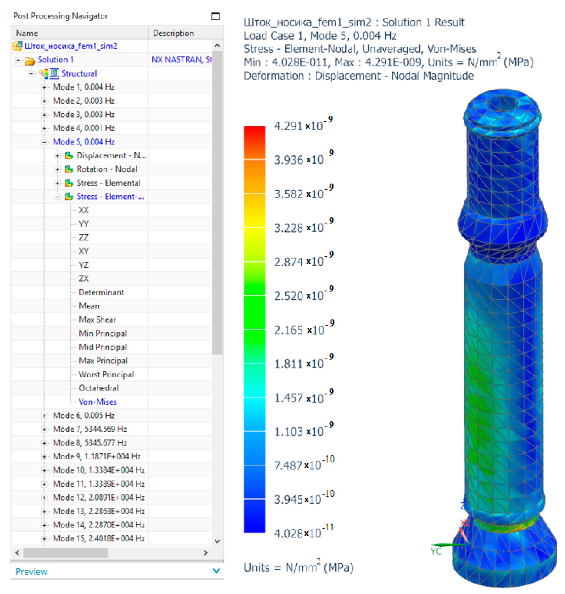
Section 6 is devoted to the finite element analysis of the DD rod under dynamic conditions, which was destroyed during the first tests of the layout, as a result of which a more thorough analysis was required;
Section 7 describes the design of the prototype DD and experimental research with the results provided; and
Section 8 formulates a conclusion on the work performed.
2. Requirements for the Parameters of the DD and the Proposed Design
Working in biological laboratories involves aliquoting the biological fluids of various patients. Aliquot dosing takes place using replaceable disposable tips, which must be changed after each dosage. At the moment, dosing with the help of manual dosing devices prevails, where the operator does all the work. Automated dosing devices, in the vast majority, are part of a robotic system, have a high price, and cannot be used in other robotic systems. To solve this problem, a modular dosing device that can be installed on any manipulator and is capable of performing all necessary operations is proposed. The design of a robotic system (RS) for aliquoting biological fluid with a modular dosing device is shown in
Figure 1.
The proposed robotic system (RS) includes housing 1, in which there is a sterile work area 2 with clean tips 3, a tripod with small volume tubes 4, and a test tube with biological fluid 5. The manipulator 6 is fixed on the base 7 and positions the dosing device 8. The biological fluid is divided into two fractions, blood serum 9 and clot 10. Due to the algorithms of the technical vision system 11, the boundary between fractions and the coordinates of the blood serum is determined, after which the manipulator, using a dosing device, performs sampling into the tip and dosing of serum into a tripod with small volume tubes.
The following requirements for the dosing device were compiled to implement automated dosing in the process of blood aliquotation:
The operations that the dosing device (DD) must perform are fixing the pipette, taking biological fluid, draining the liquid in equal parts, and dumping the tip.
The DD must be able to work with standard laboratory tips, the manufacture of which is regulated by the ISO 13485 CE 100UL certificate [
18].
The parameters of the tip are most often used for blood aliquoting: volume up to 1 mL, diameter of the larger hole , diameter of the smaller hole 0.7 mm, height 60 mm, material of manufacture plastic, without filter element.
The weight of the DD should be minimized, which will allow for low-load work. DD tests are planned to be carried out on robots available in the laboratory, with a load capacity of 0.5, 3 and 6 kg. Accordingly, the maximum mass of DD is selected to be no more than 0.5 kg.
The ability to dose liquid with a density of up to 1110 kg/m3, which corresponds to the maximum blood density.
The possibility of manufacturing a dosing device using 3D printing.
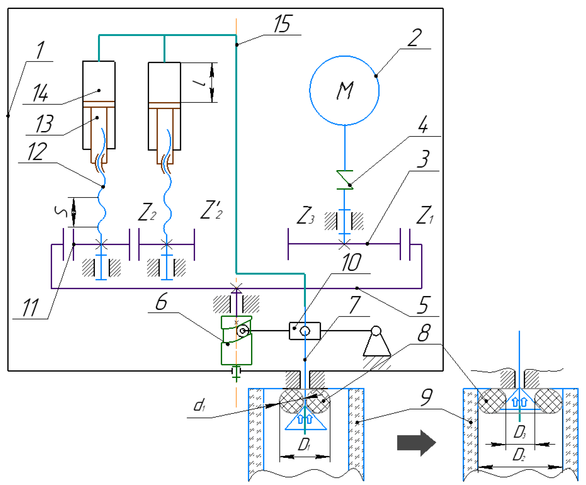
To meet these requirements, consider the following technical solution DD for performing operations: automatic fixing of the tip, liquid dosing, discharge of the tip; see
Figure 2. DD includes the housing assembly 1, in which the motor 2 is installed, connected to the drive gear 3, due to the motor coupling 4, which ensures the rotation of the external gear wheel 5 and cam 6. When the cam is rotated, the rod 7 is displaced, which deforms the elastic O-ring 8. In the initial state, the diameter of the sealing ring is equal to D1 and is smaller than the diameter of the tip 9, and in the deformable state, D2 is larger than the diameter of the tip 9, which allows for the capture and sealing of the tip 9. The rod is connected to the cylindrical cam by means of a lever 10. The gears 11 are rigidly fixed to the corresponding screw of the piston 12, each of which rotates around its axis and are is connected to the piston 13. The pistons are translationally moved in the chamber 14 of the pneumatic cylinders, which provides a discharge in the vacuum line 15 and allows for the intake of liquid into the sealed tip 9.
Since the rubber seal must be placed in the tip, it has the following limitations: the outer diameter in the initial and deformable state is
mm, and the inner diameter of the seal, D
3, must be larger than the diameter of the rod. Based on the standard ISO 3601 [
19] solutions available, the most suitable is a rubber seal with an outer diameter of 6.5 mm and a cross-section diameter from 0.1 to 3 mm. The parameters of the rubber seal D
1 = 6.5 mm and d
1 = 1 mm are selected, which will allow the sealing ring to be installed on a rod with a diameter of 1 mm.
In the described mechanism, the motor drives the pneumatic system as well as the rod, which deforms the O-ring. The DD should have a small mass and compact dimensions, which means that it is necessary to design considering the minimization of dimensions as well as to prevent the installation of an engine with excessive power and weight. Thus, it is necessary to determine the minimum torque to ensure the operation of all DD mechanisms. Let us determine the required torque for the engine.
3. Mathematical Model of the Dosing Device
The mechanism of fixing the tip is the most loaded, since deformation of the O-ring to achieve a rigid fixation of the tip can occur with considerable effort. To determine the torque required for the operation of the tip fixation mechanism, we will conduct a kinetostatic analysis.
When the rod moves, the rubber seal must change the diameter; see
Figure 3a. For uniform deformation, the rod shape is made in the form of a cone, which, when moving forward, causes an increase in the radius R (deformation) of the O-ring. Let us make up the task condition. Assume that the O-ring is made of a rubber cord with a length of
and a mass of m. The ring is put on a smooth cone with an angle of 3α at the top; see
Figure 3b,c. Let us determine the tension force T arising in the ring. To do this, select an infinitesimal element of the cord with length
and mass
, which are determined by the angle
β. Gravity
acts vertically downwards on it, the resulting elastic force
is directed from it to the center of the circle, and the reaction force of the support N is normal to the surface of the cone; see
Figure 3.
Under the condition of the equilibrium of the system, the projection of forces on the X and Y axes is determined by the following expression:
where
.
Let us assume that at small angles,
. The angle
β can be determined from the following expression:
, and
, where
is the relative change in length. Let us write down Hooke’s law in relative form:
Then, we express and define the tension force
T taking into account the assumption ∆
; then, we define
T as follows:
where
E is the Young’s modulus for the O-ring material [
20],
S is the cross-section of the cord. Let us express the friction force, provided that the rod moves inside the O-ring without rotation. Then the expression takes the following form:
where
μ is the coefficient of friction between the material of the sealing ring and the material from which the rod is made, rubber and steel are used in the calculation. The design scheme of the rod lifting mechanism is shown in
Figure 4a. The mechanism works as follows: the lever CA is fixed on a rotary joint A and has a slider B, which in turn is fixed on a rod that deforms the O-ring. The diagram of the stem with an O-ring is shown in
Figure 4b. The lever CA rotates at an angle γ due to sliding along the profile of the cylindrical cam at point C, which leads to a vertical displacement of the rod.
To determine the required torque on the cylindrical cam to lift the rod to a given height
, we determine the height of the profile
and the force
, taking into account the difference in the lengths of the shoulder
and the total length of the lever
using the following expression:
In order to determine the dependence of the force
and the torque
M1 required to achieve it, let us assume the surface of a cylindrical cam in the form of an expanded inclined surface on which the slider C slides; see
Figure 5.
To turn the cam, it is necessary to apply torque M1, according to the formula . Where is the torque of friction force on the support end, is the torque of force on the cam profile , and f is the reduced coefficient of friction.
According to the well-known theorem of mechanics, which considers friction forces, the slider is in equilibrium if the resultant
Fn of the system of external forces is deviated from the normal
n − n by the friction angle
ϕ. In our case, the external ones are the axial force
and the circumferential force
. From the force triangle in
Figure 5b, we can find the unknown force
and determine the desired torque:
where
is the angle of lift of the cam helical surface,
φ is the angle of friction of the cam helical surface. The moment of rotation of the gear wheel is expressed and defined as follows:
Let us determine the force to be applied to the piston to lift the liquid column in the pipette to the required height, considering atmospheric pressure; see
Figure 6.
The required torque of the screw for the movement of the pneumatic cylinder rod is determined similarly to the expression (6), then
where
is the angle of the thread on the piston rod
, is the pitch of the screw,
is the diameter of the threaded rod,
is the diameter of the piston, and
is the force acting on the piston from the threaded rod, as a result of atmospheric pressure
. Where
is normal atmospheric pressure,
is the force acting on the piston from the side of the vacuum line, which is determined by the following expression
. Where
is the density of a column of liquid that rises to a height
H,
is the friction force in the piston seals
, where
—the coefficient of friction accepted for rubber cuffs;
—width of the contact surface of the seal;
—pressure in the pneumatic cylinder.
The required engine torque is defined as the sum of the rotational torques of the corresponding gears, taking into account their gear ratio.
where
is the number of cogs of the corresponding gears. Considering the fact that
the torque
is equal to
Expression (9) allows you to determine the maximum torque of the engine, considering all of the design parameters. However, some of them may vary within certain limits. So, the diameter and height of the piston stroke can change, leaving the torque unchanged. To determine the most preferred configuration, we will optimize the geometric parameters of the DD.
4. Optimization of Geometric Parameters of the Mechanism
First, we obtain simple expressions that define the relationship between the geometric parameters of the device and its performance. We assume that, considering the gear modulus , the linear displacement of the piston per turn of the engine , where is the number of cogs of the gears and, is the pitch of the screw.
To take the required volume of liquid
with a piston diameter
, the stroke of the rod
is required, and this dependence allows you to obtain the required geometric parameters of the mechanism for taking a given volume of liquid equal to 1000 mm
3. Let us take into account only the working stroke of the mechanism
without taking into account the fixation
, and substitute the required number of cogs,
where
n is defined as
. The volume of the tip is known as
, while the metering device must be compact, respectively. For the smallest gear wheel, the minimum number of cogs
is selected, and the diameter of the piston
may vary. The number of required cogs
depends only on the thread pitch
of the rod.
The dividing diameter of the gear wheel
is determined by the following:
Thus, it is possible to determine the maximum dimensions of the gears and draw a conclusion about the dimensions of the metering device; however, a number of parameters may be different.
To determine the values of the design parameters, we use multi-objective optimization methods. To do this, we will find many solutions with different design parameters for the mechanism under given constraints. We will find out from the whole set those that will have the minimum values: the torque M2, the outer diameter of the case , and the height of the dosing device .
The formulation of the optimization problem involves the selection of criteria and constraints on the parameters. Let us consider the optimization criteria:
Let us consider the optimization parameters: the thread pitch on the piston rod , the diameter of the piston , and the angle of rotation of the external gear wheel to raise the rod to a predetermined height. Optimization limitations include the following: the thread pitch on the piston rod should not exceed 4 mm since the dosing accuracy will drop significantly as well as the required torque, which will increase many times; the minimum thread pitch should not be less than 1 mm since 3D printing will be difficult; and the movement of the rod per engine revolution is very small; therefore, 1 < < 4 mm. The diameter of the piston cannot be larger than the radius of the outer gear, as this will lead to an increase in the dimensions of the DD, and a very small piston size will require a large stroke of the piston rod, which will also increase the dimensions; then, we will limit the diameter of the piston within . The angle of rotation of the external gear wheel to raise the rod to a given height can vary from 0° to 360° degrees; however, at 0°, the angle of elevation of the plane along which the lever slides will be vertical, and at 360° degrees, the angle is smooth, but the tip is fixed until it is completely rotated, which is unacceptable. Therefore, we limit the fixation of the tip to a quarter turn of 0° < θ < 90°.
To reduce the number of criteria and thereby build a Pareto set more efficiently, we will perform the convolution of criteria 2 (maximum diameter
) and 3 (maximum height of the device
) into one criterion, which is the volume
occupied by the excavating device.
As optimization algorithms, we use evolutionary algorithms that are widely used to solve similar problems [
21,
22,
23]. One of the solutions is the “gamultiobj” module, which is included in the MATLAB 2019 software package and allows the use of a genetic algorithm to solve the problem of multi-objective optimization, including for shapes and surfaces, as shown in a number of studies [
24,
25,
26]. To ensure the reliability of the result, two modifications of the multi-objective optimization (MO) algorithm developed earlier by the authors [
27] were used, one of which is based on the parallel GWO algorithm (MO-GWO), and the second is based on the parallel PSO algorithm (MO-PSO).
Let us set the initial data for a computational experiment. The values of the constants used in the simulation are shown in
Table 1. The parameters
and H are taken in accordance with the parameters of standard tips; the friction coefficients μ,
, and
, as well as the Young’s modulus
are selected in accordance with the selected materials of manufacture of all elements; the angle at the tip of the cone α° is selected experimentally; and the number of cogs
is selected as the largest possible for the selected design.
Optimization parameters ranges: ∈ [0.0001; 0.0025], ∈ [; 0.5], ∈ [0.00001; π/4].
The algorithm parameters were selected considering an approximately equal number of total iterations for the correct comparison of algorithms. Parameters of the NSGA-II algorithm of the «gamultiobj» module: the number of individuals in the population
= 10,000, the number of generations
= 100. The total number of iterations of calculating the criterion function as a result is
The parameters of the MO-GWO algorithm are as follows: the number of stages, the number of grid nodes for each criterion for sorting the importance coefficients
= 16, the number of stages for each grid node
= 2, the number of individuals in the population at each stage
= 390, and the number of generations at each stage
= 5. So, the total number of iterations is the number of iterations.
where
is the number of iterations to calculate the average value of the coefficients, not exceeding 1600 iterations.
The optimization of the MONO and MOGWAI algorithms is performed using a software module in the C++ programming language. Parallel computing is implemented using the OpenMP library. The visualization of the results was performed using a Python script (Matplotlib and JSON libraries). A computer with a six-core processor and a frequency of 3.79 GHz was used for the simulation.
The calculation time and the proportion of approximation points in the resulting Pareto front obtained by each of the algorithms are used as metrics of the effectiveness of the algorithms. The optimization was performed 10 times.
Table 2 shows the number of Pareto points and the proportion obtained using each of the algorithms. The average calculation time for the NSGA-II algorithm was 43 s, for MO-GWO it was 9 s, and for MO-PSO it was 3 s.
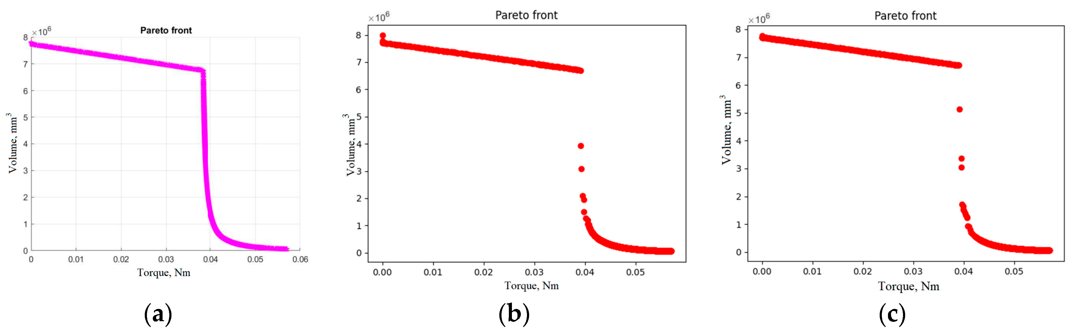
Figure 7 shows an example of the Pareto set obtained by each of the algorithms for experiment 4. The horizontal axis corresponds to the required torque, and the vertical axis corresponds to the volume of the DD.
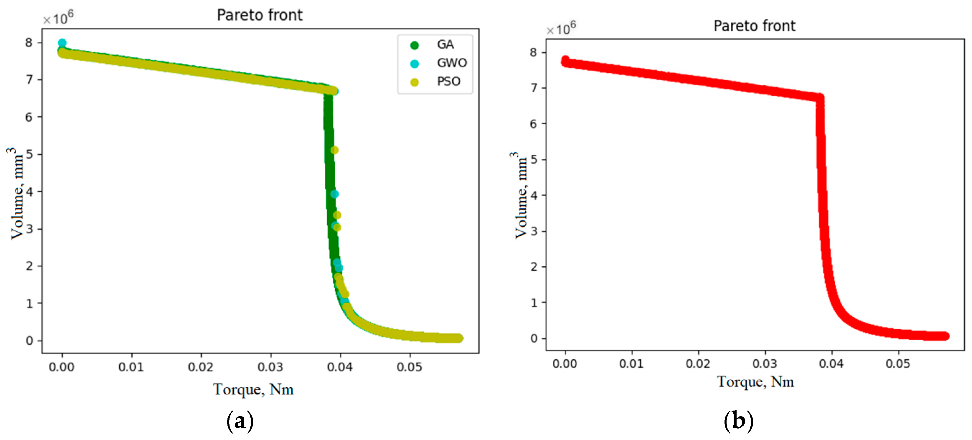
Figure 8 shows a comparison of each of the Pareto sets and the resulting Pareto set.
As can be seen from the graphs, the NSGA-II algorithm made it possible to obtain a more uniform distribution of the Pareto set, in particular in its central zone. Nevertheless, the resulting Pareto set had an average of 57.9% of the points obtained by the MO-GWO algorithm compared with 33.1% by the NSGA-II algorithm. Due to the significantly higher performance of the MO-GWO and MO-PSO algorithms in comparison with the NSGA-II algorithm, additional computational experiments were performed to compare the efficiency of the algorithms with an equal calculation time. The NSGA-II algorithm’s operating time, which is 43 s, was taken as the total calculation time. To bring the time to an approximately equal value, the parameters of the MO-GWO and MO-PSO algorithms were changed as follows: , and .
With equal computation time (
Table 3), the MO-PSO algorithm made it possible to obtain an average share of 54.8% of the points of the resulting Pareto set, MO-GWO achieved 35.8%, and NSGA-II achieved only 9.4%. However, the MO-PSO algorithm, even with equal computation time, did not allow us to obtain a uniform distribution of points in the central part of the Pareto set (
Figure 9).
The linear section of the Pareto front corresponds to the parameters of the DD, in which the radius of the outer gear is always larger than the diameter of the piston and is a key factor in determining the volume, while the torque is the lowest as a result of the highest gear ratio; however, there is a curved section on the graph where the diameter of the piston becomes the decisive value for the volume of the DD; in this case, the required torque can increase many times.
The torque of the selected stepper motor is 0.0441 Nm based on the obtained Pareto set, the closest value is 0.0406 Nm, for which the geometric parameters are accepted. The calculation results and the values of the calculated parameters that are not given in the description are presented in
Table 4.
7. Building a Prototype and Testing
A design of a dosing device using 3D printing has been developed, see
Figure 16, for the construction of which relevant scientific works in the field of additive technologies were used [
34,
35]. A 28BYJ-48.5 V stepper motor is used as a drive, which is connected to a frequency converter.
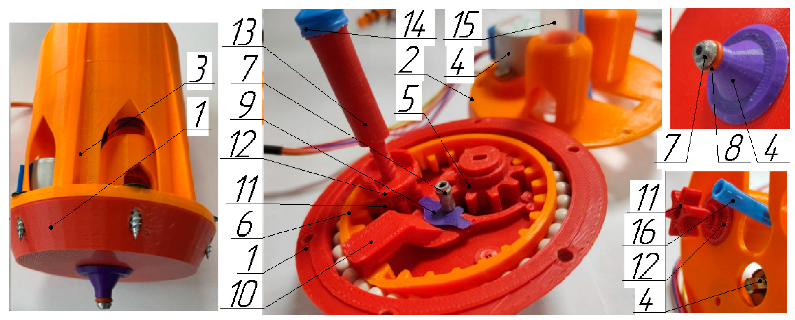
The DD layout consists of a composite housing, including base 1, cover 2, and top 3. An engine 4 is installed in the housing, connected to the drive gear 5. An engine 4 is installed in the housing, connected to the drive gear 5. The driving gear 5 provides rotation of the external gear 6, which has a pushing profile at the end. When the outer gear is rotated by ten degrees or more, the rod 7 is displaced, which deforms the elastic O-ring 8. In the initial state, the diameter of the sealing ring 8 is equal to D1 and is smaller than the diameter of the fixed tip, and in the deformable D2, it is larger than the diameter of the tip, which allows for gripping and sealing. The rod 7 is coupled to an external gear wheel by means of a washer 9 and a lever 10, the use of which increases the clamping force. The lever 10 has an upper position in the range from 11 to 350 degrees of rotation of the external gear 6. In this range, each gear-screw 11 rotates, which is a single part consisting of a gear to which the screw is perpendicular and coaxially fixed. The forward movement of the pinion screw along the axis of rotation is limited by the stopper 12. This allows, as a result of rotation, to move the piston 13, on which the seal 14 is installed. Each of the pistons 13 translationally moves in the chamber of the pneumatic cylinder 15. The movement of the pistons in the chamber of the pneumatic cylinder provides a discharge in the vacuum line 16, which allows for the intake of liquid into the tip.
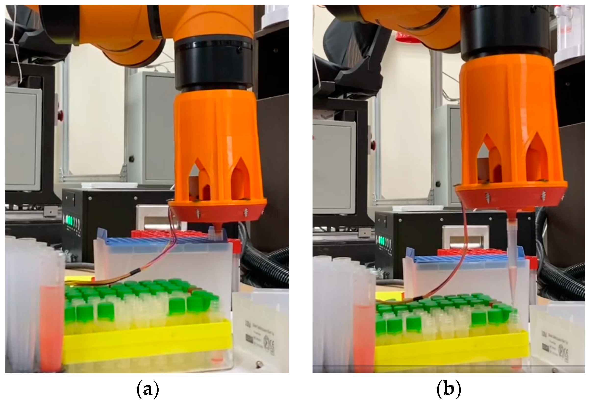
The motor rotation is controlled using an Arduino UNO, which is connected to the control panel of the AUBA i5 robot. The power supplied by the robot is controlled by two switches for various tests; see
Figure 17a,b.
The control program of the AUBA i5 robot was developed to conduct the experiment. As a result, the robot grabs the tip, positioning it over a test tube with a liquid emulating a biological one. Liquid is taken in the amount of three equal fractions of 2 mL each; the dosing device is positioned above a small volume tube; three fractions are alternately drained into a small volume tube; and the tip is discharged. The experiment has been repeated many times.
8. Results and Discussion
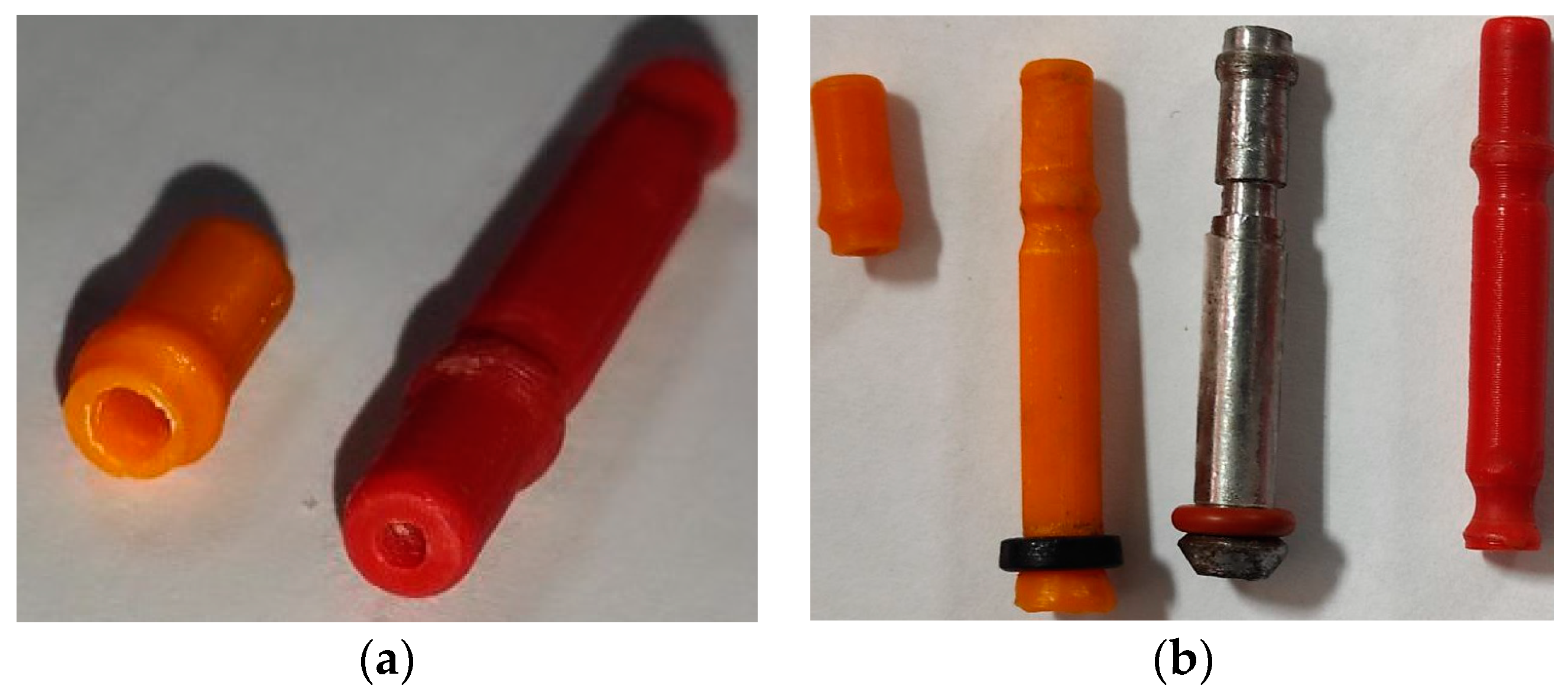
The torque of the selected stepper motor is 0.0441 Nm, which is about 8% higher than the required operating time of the metering device, as a result of which, after 15 min of operation, the engine was significantly heated. It was possible to reduce the load on the engine by installing an O-ring made of softer rubber, which is shown in
Figure 15b, mounted on a rod made of metal.
In 19 cases out of 20, the robot coped with fixing the tip and dosing the liquid; however, inaccurate dosing occurred, and contamination of the equipment was recorded (liquid got on the work surface). It was revealed that in the case of sequential immersion and liquid intake, partial liquid intake occurs due to the compression of gases in the vacuum line. Therefore, the intake of the correct volume of liquid is feasible in the following cases: When the tip is immersed to a level of no more than the volume being withdrawn (
Figure 18a), it is necessary to synchronize the speed of liquid intake and the movement of the manipulator. It is also possible to correct the error at the software level, considering the proportion of self-collecting liquid.
During the intake of liquid, a micro drop occurs (
Figure 18b), which can lead to contamination of the equipment. This can be avoided if, after taking the liquid, a small amount of air is taken, in which case a drop forms inside the tip and is unable to get to the work surface. The volume of air intake is calculated by the number of turns of the engine and is considered when dosing. There are studies on microdosing [
36], which describe the modernization of the tip surface to eliminate the formation of micro drops on the surface.
However, our current research work still has some limitations. On the one hand, the resulting prototype is more of an experimental sample and only proves the correctness of the research methods. The metering device must be tested in real conditions during long hours of operation and ensure the required reliability. The question of fixing the measurement error of the dosed liquid also remained open. It is necessary to research feedback methods for dosing small volumes of liquid in more detail. On the other hand, the theoretical analysis and design of the dosing device in this research are carried out within the framework of the formulated requirements for a specialized task. In particular, for dosing biological fluid with a single replaceable tip, which is significantly slower than known laboratory dosing units with multiple tips, this is only the first step in our research. In future work, the dosing device will be studied as part of the aliquoting system of biological material, and a more advanced control system will be presented.


