1. Introduction
The comprehension of surface wear processes traces back to Hailing’s pioneering work in the 1970s [
1], which defines surface wear as an inherent outcome of the interaction between two bodies experiencing relative motion, manifesting as an irreversible material loss from the surfaces involved. Notably, even macroscopically smooth surfaces reveal significant roughness when scrutinized at the atomic scale. Therefore, when two surfaces are in contact, wear occurs at a few isolated asperities. For this reason, applying a normal load results in extremely high local pressure on these asperities in the contact zone. In the presence of surfaces with a high degree of surface roughness, the yield stress is, therefore, easily exceeded, and the asperities plastically deform until the area can withstand the applied load. Conversely, in the case of a relatively smooth surface, the asperities deform elastically to support the load.
In the course of our investigation, we focused our attention on abrasive wear, an intricate phenomenon induced by the mutual sliding interaction of rigid and rough surfaces, or surfaces incorporating rigid and protruding particles. This particular form of wear, which is evident during the operation of reinforced polymer gear wheel transmission systems, is characterized by the removal of particles in the form of microchips. This phenomenon is in fact characterized by the formation of grooves and scratches on the softer surface or, in some instances, on both interacting surfaces.
The assessment of wear in a gear wheel system is a highly intricate task, yet it holds paramount significance in elucidating the system’s performance, reliability, and overall lifespan. Understanding the complex dynamics of wear in such systems is essential for optimizing their design, enhancing their operational efficiency, and mitigating potential issues associated with their long-term usage.
If for transmission systems with metal gear wheels, the experimental techniques for evaluating wear are quite consolidated, for reinforced polymer wheels there are still no consolidated scientific studies.
Speaking of polymer gears, the definitions and specific information on the wear of gears can be found in the AGMA and VDI standards [
2,
3]. According to AGMA, wear of the teeth of gears is a superficial phenomenon in which layers of material are removed uniformly from the tooth contact surface. Tooth wear in gear engagements generally begins with the phenomenon of polishing, which is the polishing of the tooth surface. If tooth engagement continues for an extended period, it progresses through an initial phase of mild wear and eventually reaches severe wear, characterized by a significant reduction in tooth thickness [
4]. An excellent dissertation on the wear of polymer composite gears can be found in Mao’s PhD thesis [
5]. Deep studies on metal-polymeric gear coupling began with Hackmann and Strickle [
6], who developed an empirical formula for calculating the wear of nylon gear teeth when they mesh with steel gear teeth. The maximum allowable wear was provided as a function of the gear’s module; however, experiments showed a difference of more than 50% between wear calculated using this formula and the measured wear. These results highlight how it is necessary to create test benches capable of simulating the operating conditions of the system as realistically as possible.
Yousef [
7] described research conducted in Germany, which demonstrated that when meshing steel gear wheels with plastic materials such as nylon 6 and nylon 66, the nylon 6 gear wheels exhibited significantly more wear than the nylon 66 gear wheels when subjected to the same number of cycles. Padmanabhan [
8] noted that when coupling nylon gear wheels with steel gear wheels without lubrication, wear was low. It was also demonstrated that lubricated nylon gear wheels exhibited approximately 2.6 times less wear than when analyzed in dry running, even when the cycles performed by the lubricated gear wheels were about twice as many as those of the non-lubricated ones. As the number of cycles increased, there was also an increase in the distance between two parallel planes tangential to the sides of the opposing teeth, likely due to excessive tooth deformation.
Yousef [
7] studied wear in the pairing of plastic gear wheels and observed that wear increased with an increase in transmitted torque, tooth width, and pitch line velocity. It was also observed that the increase in wear was not consistent but was greater in the initial phase of the gear’s life and lower after a certain number of cycles, a result attributed to a decrease in average roughness. Subsequent studies yielded results that contradicted this hypothesis, as it was noted that roughness increased in the final phase of the gear’s life. Yelle and Poupard [
9] defined wear as the average decrease in tooth width measured at three points. The three mentioned points correspond to the intersection between the tooth flank and the head, base, and pitch line circumferences. Studies revealed that the wear just described was much lower in lubricated gears compared to gears without lubrication.
Terashima [
10] studied wear in the pairing of nylon gear wheels and steel gear wheels, observing anomalous values of the latter at the root of the polymer gear wheel’s teeth. These values resulted from the scraping action of the metal gear tooth’s tip. Wear, starting at the root, extended to the head as the number of cycles increased, resulting in elevated temperatures and fractures at the primitive circumference. More recent works on this topic are reviewed by Singh [
11].
An interesting discussion, useful to highlight the differences among the different possibilities for wear testing, measurement, and characterization of fiber-reinforced polymeric wheels can be found in Wright and Kukureka [
12]. The sliding and rolling characteristic of gear contact are experimentally identified and well explained in this paper, and following this paper, it is easy to understand why the simple sliding pin-on-disc tests considered in VDI testing are not accurate enough to describe the complete wear mechanism between plastic-reinforced and steel gears coupling. For detailed information on conformal testing for pin-on-disc testing, see [
13].
More recently, the paper of M. Hribersek [
14] contributed to the understanding of the wear mechanism in a time sequence from the start-up to a failed gear, where a steel/POM gear paired material is of interest. Gear geometry, quality, testing arrangement, and procedure were disclosed in this context. Propagating flank wear was observed by a 3D optical scanning device.
In Mert Safak Tunalioglu’s study [
15], the wear resistance of plastic spur gears produced by the Fused Deposition Modeling (FDM) method was determined with the in-service life of gears. The wear tests were carried out in a Forschungsstelle fur Zahnrader und Getriebebau (FZG) type test device at the same load and rotational speeds.
In all cases examined, the experimental tests were carried out under ambient temperature conditions. While this does not have much influence on metal wheels, the influence of temperature when testing polymer wheels is of fundamental importance.
The examination of the existing state-of-the-art methodologies employed in test benches for assessing the coupling between toothed wheels made of polymers, reinforced polymers, and steel reveals, however, a challenging landscape in terms of regulatory application, particularly in non-conventional scenarios such as temperature tests.
For these reasons, in the specific context of this research, our focus was on devising a specialized test bench tailored to evaluate the tooth wear of gear made of various polymers, even those without reinforcement such as acrylonitrile butadiene styrene (ABS), polylactic acid (PLA), polyamide 12 (PA12, also known as nylon 12), polyetherketone (PEAK), and polyetherimide (PEI), manufactured through different production methods, which may also involve additive technologies [
16], tested under non-conventional temperature conditions, during contact.
In the specific case of our study, the wheels tested on the bench were manufactured through injection molding using PPS loaded with short glass fibers, a material provided by Sabic. The conceptualization of our test bench draws inspiration from Mao’s work [
17,
18], which elucidates the loading mechanism applied to gears.
For this reason, this manuscript dedicates its initial segment to a detailed exposition of Mao’s test bench, providing a foundation for subsequent discussions. The ensuing sections delve into the intricacies of our designed test bench, emphasizing distinctions from the existing counterpart and showing in detail the solutions adopted for its inclusion in the climatic chamber.
This detailed description of the test bench we created aims to contribute to the development of new systems to fill the need for evaluating the wear of reinforced polymer gears in non-standard temperature conditions.
2. Basic Test Bench Design
The test bench, developed in collaboration with an EU automotive component manufacturer, falls into the category of mechanically loaded closed-loop test benches and draws inspiration from the work of Professor Kun Mao and Professors D. Walton and CJ Hooke of the University of Birmingham [
19]. The aim was to design a test bench capable of measuring the wear on the surface of a plastic gear subjected to constant loading conditions. In the initial design phase, it followed the guidelines provided in [
20], proceeding to create a closed-loop test bench, the initial basic schematization of which can be observed in
Figure 1.
It is worth noting that in this case, the torque is applied statically through a clamping joint. Since this load needs to remain constant throughout the test, the test bench must be designed in a way that prevents wear on the teeth from causing a drop in clamping torque due to changes in gear contact. The gear wheels in the transmission gears should have the same dimensions as the gears being tested. Additionally, it is useful to insert a second torque sensor to record any losses between input and output. The other measurements are the same as those for the mechanically unexcited closed-loop test bench.
A schematic representation of the test bench is represented in
Figure 2. The motion transmission occurs through an electric motor (1) connected to the driving shaft (4) via a belt drive (2). Inside the test bench, there is a slave gearbox (3) containing a pair of metal gearwheels identical to the gearwheels that will be tested and that do not require replacement over time. The driving gearwheel and the driven gearwheel in the test gearbox are connected to the corresponding gearwheels under test, made of polymer material, through four universal couplings (5). A notable feature of this test bench is the procedure by which the constant torque is maintained for the gearwheels under test (9). The test gearbox is allowed to rotate by hinging it on an independent block, preventing gear wear from affecting the supplied torque. The torque applied to the gearwheels under test is generated by a system consisting of a loading bar (6) connected to a weight whose mass depends on the desired load intensity (7). A block inserted beneath the test gearbox (8) ensures that the rotation of the gearbox is locked in case of plastic gear failure.
2.1. Analysis of the Load Applied to the Test Wheels
By observing the balance of moments concerning the shaft pivot (10), the constant torque provided by the weight (7) applied to the test wheels is counterbalanced by the twisting moments acting on the shafts (9). It can be noted that the two torques and have opposite directions to the moment due to the weight.
Assuming there is no friction on the pivot bearings, we have the following relationship (see
Figure 3):
where:
W is the total force applied to the end of the rod where the weight is located [N].
L is the horizontal distance between the point of load application and the rotation pin [m].
T1 is the torque at the motor shaft 1 [N∙m].
T2 is the torque at the driven shaft 2 [N∙m].
If friction (DT) is considered, it is possible to derive:
With the knowledge of T, the torque at the gears, it is simple to derive the forces on the wheels with the usual formulas for gearing (considering tangential forces applied as
):
It is simple to prove that, considering a dynamic friction coefficient of the bearings equal to
, the friction torques are negligible with respect to T (see [
21] for details).
2.2. Rotation Due to Wear
Kun Mao correlated the work absorbed by the gear teeth during meshing, in the presence of wear, with the angle of rotation
of the gearbox around the pin caused by the weight. In particular, he stated:
where:
is the mean wear on a single tooth thickness due to friction [mm].
is the primitive diameter of the wheel
is the pressure angle of the wheel
is the rotation angle of the gearbox on the rotation pin due to the teeth thickness reduction (the reduction is considered equal for both teeth in this equation).
This rotation angle
will be employed for monitoring the gears under test and intervening in the event of sudden wear variations associated with tooth breakage phenomena. The rotation angle gamma is acquired in real-time by evaluating the displacement of a specific point
on the main gearbox (the position sensor, close to point 8 shown in
Figure 3), knowing the distance
of the measurement point from the hinge (10) in
Figure 2. Consequently, the rotation can be calculated as
.
Through Equation (4), it is possible to derive a critical average assessment of friction wear without interrupting the experimental phase. This allows us to avoid frequent interruptions during the test and focus attention only when approaching the critical operating condition (which is variable depending on the specific application, with an acceptable wear level defined based on the type of application). In the context of the automotive industry, our focal point, the emphasis lies not solely on wear but on sustaining component functionality. Therefore, even with a significant reduction in wheel thickness, this may not affect practical performance. The typical threshold for wear in the automotive field to halt a test is around 20% of the nominal value. Additionally, there is a significant advantage in using Equation (4) for real-time monitoring of average tooth wear. Studies such as Yousef [
7] and others demonstrated that wear curves as a function of applied load are linear up to a certain torque value (dependent on the material and wheel geometry) before transitioning to an exponential trend. Monitoring average wear thus provides insight into estimating the torque level at which the linear wear behavior transitions to friction-induced exponential wear.
The average linear wear Wm, as required by gears standards, is estimated through optical methods, stopping the tests when required (as an example, at a fixed cumulate rotation of the wheels, such as every 100,000 cycles).
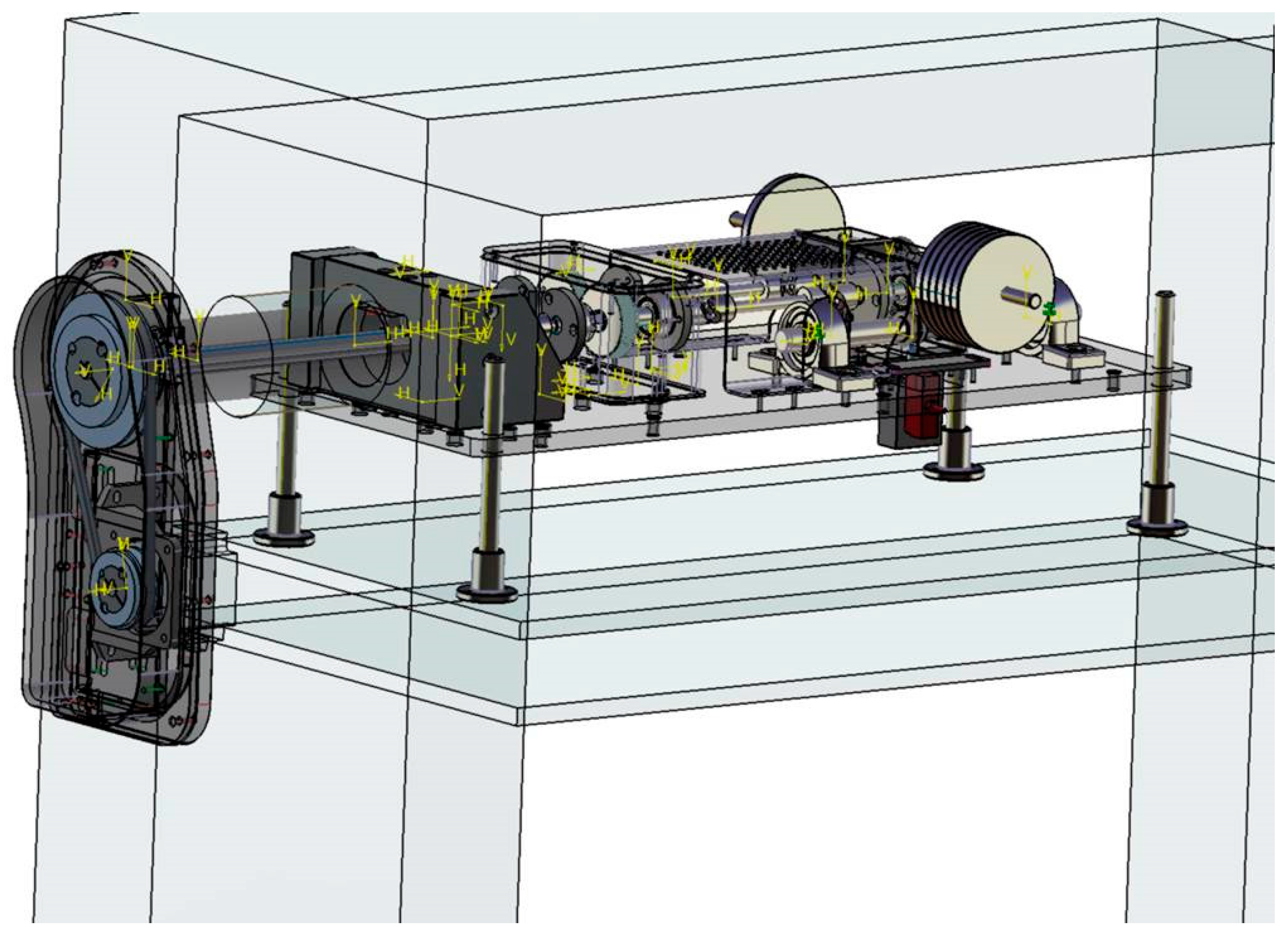
Before proceeding with the construction of the bench, a detailed multibody model of the test bench was developed to test the realistic behavior of the system. A complete schematic virtual model is shown in
Figure 4 below. The torque transmission system (1 and 2 in
Figure 2) was omitted and different nominal torques were considered as the input of the system. The results of the virtual multibody model confirmed loads on the parts to be considered in the system’s mechanical design.
2.3. Load Torque Measurement
Before proceeding with the description of the geometric changes that characterize the new test bench, it is important to discuss and describe how a fine torque measurement is carried out because the exact load measure is a crucial point for the goodness of the wear test.
In
Figure 5, the position of the load cell used for weight measure (torque) before the test is shown. Because the range of torque (from 0 to 2.25 Nm) needs to be tuned with extreme precision, a counterweight mass was added to the system (not present in the original test bench) with a short distance to the rotation pin to be very effective in fine-tuning the system. These first modifications are essential and indispensable for a correct measurement of the quantities involved.
As previously discussed, torque fluctuations are not a concern during the test due to the stable load condition ensured by the simple weight load mechanism.
So, even if the climatic chamber is used, the load measuring test can be performed before the test in the usual temperature condition (22 °C). To measure the applied torque, a compression load cell (details visible in
Figure 6) was used, positioned 20 mm from the pivot axis around which the main gearbox rotates. To facilitate the alignment and fixation of the load cell, a hole was drilled into the base of the test bench, and a straightforward screw was inserted. This screw, when tightened, applies pressure to the load cell support, securing it to the bench (refer to
Figure 6). It is evident that once the torque measurement is completed, the sensor must be removed to prevent interference with the gearbox oscillation.
3. Test Bench Design Adaptation for Climatic Chamber Utilization
The main challenge for the test bench is to provide wear measures up to 180 °C, which is the typical utilization for automotive plastic reinforced wheels for engine regulation tasks. This certainly represents the main evolution compared to Mao’s standard test bench, which has no chance of being effectively used in climatic chambers due to three main limitations:
The geometrical adaptation of all of the system parts is required before insertion of the system into different climatic chambers.
The utilization of the motor drive at 180 °C is not possible;
The ability to take continuous displacement measurements at high temperatures is limited.
Improvements to overcome these three limitations represent the substantial differences between our bench and the original; these improvements will be described in even more detail in the following subparagraphs.
3.1. Geometrical Reconfiguration
The typical test for polymeric gears is performed with temperatures up to 180 °C, so a climatic chamber must be used when these measurements are obtained. Ensuring effective heat circulation across all components of the system is imperative. In the typical test bench, it is very hard to stabilize the temperature in the lower part of the system.
A straightforward lifting mechanical system was designed for the entire test bench using four height-adjustable lead screws as depicted in
Figure 7. The main plate of the test bench where all of the components are fixed can be raised and/or lowered according to the desired height by simply rotating the nuts connecting the lead screws to the plates. The test bench temperature stabilization is faster when using this simple raising system.
3.2. Drive at High Temperature
Even if the necessary torque for the system is less than 10 Nm (we have only to ensure the right rotational speed), the problems of motor drive and speed control from 0 to 2500 rpm have to be solved.
Referring to
Figure 2, we have redesigned components one and two of the system by bringing them outside the climatic chamber to the drive. By providing a long shaft from the torque transmission system to the slave gearbox, a pendulum motor and transmission belt can be designed and installed.
In this way, the drive system is not affected by temperature changes and typical low-cost temperature components can be used. Also, the torque control of the motor is not affected by temperature, so the same control system with the same control parameters can be used in all conditions.
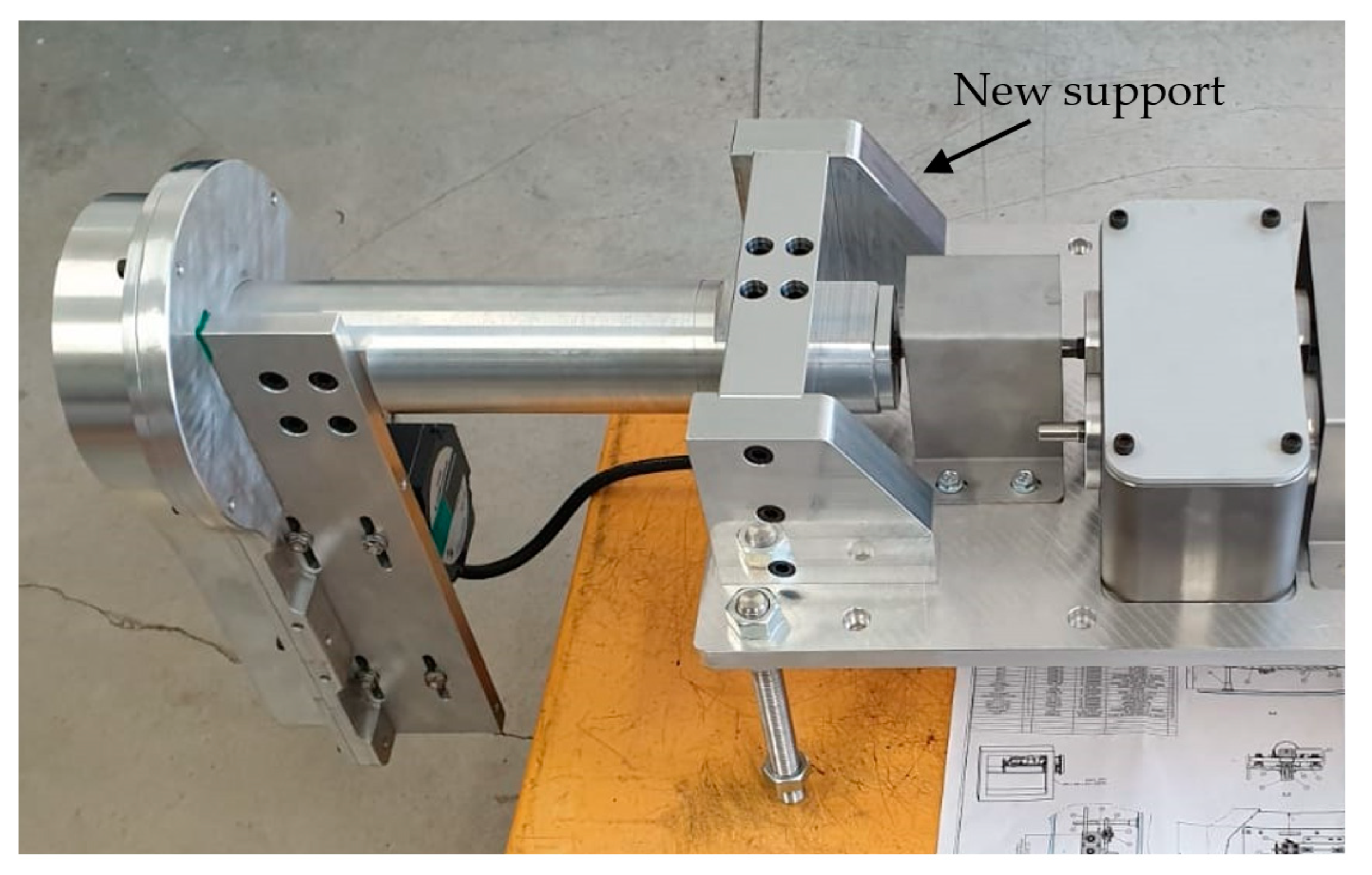
It is imperative to note that a novel support structure for the drive system must be engineered to achieve an efficient decoupling of the drive mechanism from the components housed within the climatic chamber. Without the incorporation of the new support shown in
Figure 8, the bearings on the slave gearbox will be out of duty after a few hours. All internal transmission systems within the chamber are lubricated with grease resistant to high temperatures. No lubrication issues have emerged during operation, even within the climatic chamber.
3.3. Continuous Displacement Measures at High Temperatures
The
angle is measured by a position sensor under the main plate (see
Figure 2) at a fixed distance from the pin rotational hinge.
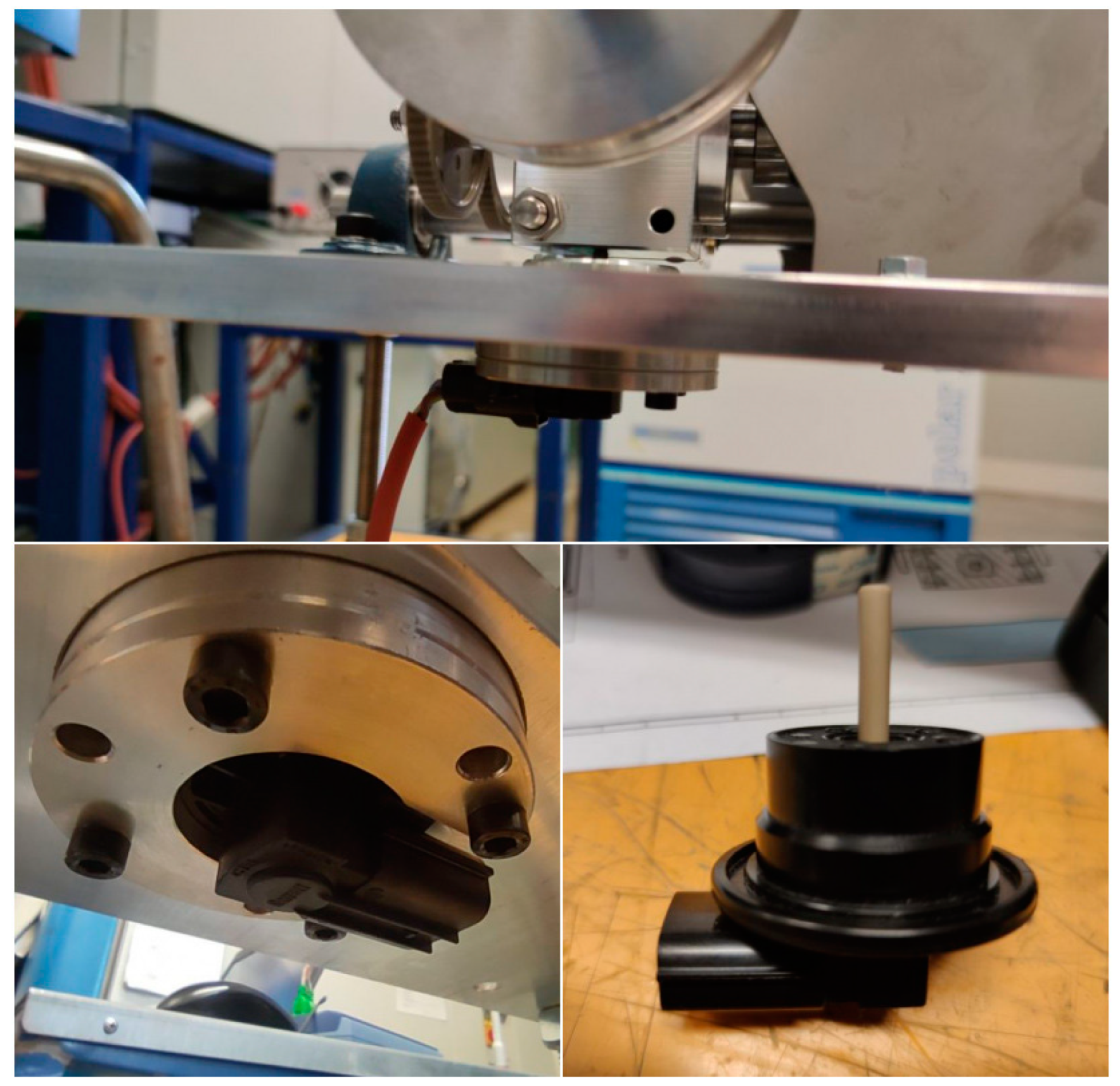
For the lowering of the gearbox due to the wear of the teeth of the gears under test, a resistive position sensor was employed (
Figure 9). The chosen transducer is directly manufactured by the EU company and is usually used in turbochargers, with very high reliability. The transducer is positioned approximately 130 mm from the pivot axis. By recording the vertical displacement, it is possible to calculate the rotation angle γ of the block and subsequently, it can be integrated into equations for monitoring the wear of the wheel as discussed in paragraph 2. Heat-resistant materials are used for all of the parts and cables necessary for the sensor system.
Some other adjustments have to be made for plastic gear testing; for example, to provide the proper fixing of wheels to the shafts without an excessive load during fixing, but these particulars are confidential for the EU manufacturer.
The voltage variation measured in volts recorded by the resistive sensor following the oscillation of the block can be visualized by connecting an oscilloscope to the test bench outside the climatic chamber.
In conclusion, following the improvements made, the test bench is now capable of testing plastic gear wheels with a nominal diameter of 60 mm, module ranging from 0.5 to 1.2, and a variable thickness between 4 and 8 mm, at temperatures ranging from −40 to +180 °C, while exerting torque up to 5 Nm.
4. Preliminary Tests and Possible Improvements
The test bench, as currently configured, is already being deployed for conducting tests under ambient temperature tests or in climatic chamber testing on gears, but the resulting wear curves cannot be shown for confidentiality reasons.
In the specific case of precise testing of friction wear, optical techniques or a mechanical coordinate measuring machine are employed in post-processing. As mentioned, this approach allows for a precise assessment of friction wear. Nonetheless, the necessity of interrupting the experimental phase imposes a substantial slowdown on the testing procedure, particularly for temperature-dependent tests.
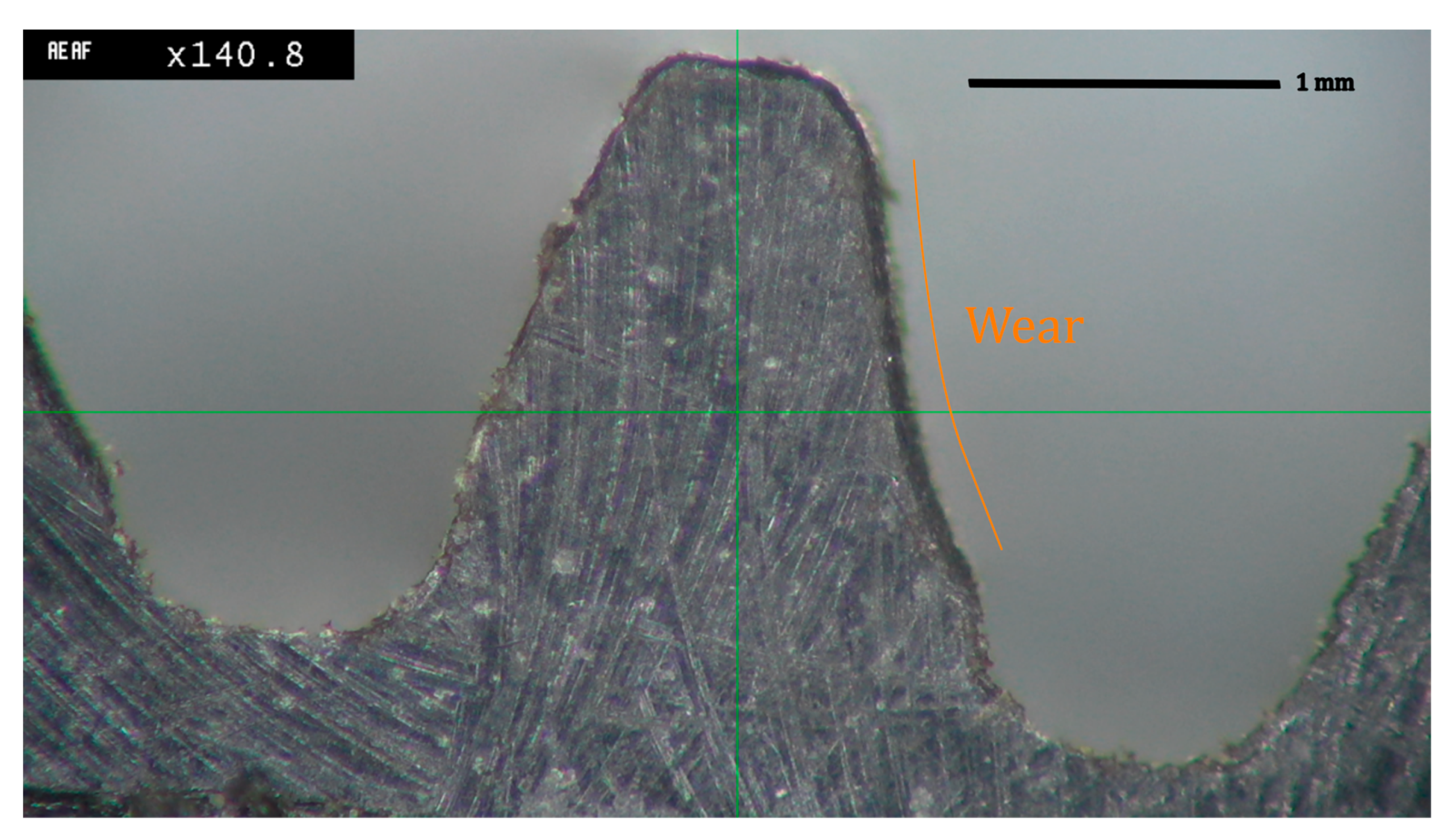
In
Figure 10, the ×140 magnified picture of a tested reinforced gear is shown, and due to magnification, the reinforcing glass fibers are visible in the picture. The image was captured using optical microscopy (OM—Eclipse LV150 NL, Nikon, Tokyo, Japan) by preparing the sample through polishing with abrasive papers. The test was performed with a test gear having a thickness 6 mm nominal diameter equal to 60 mm, modulus 1, and consequently, a number of teeth Z equal to 60. The gear rotates under load with a clockwise rotation of a 60 mm primitive diameter gear.
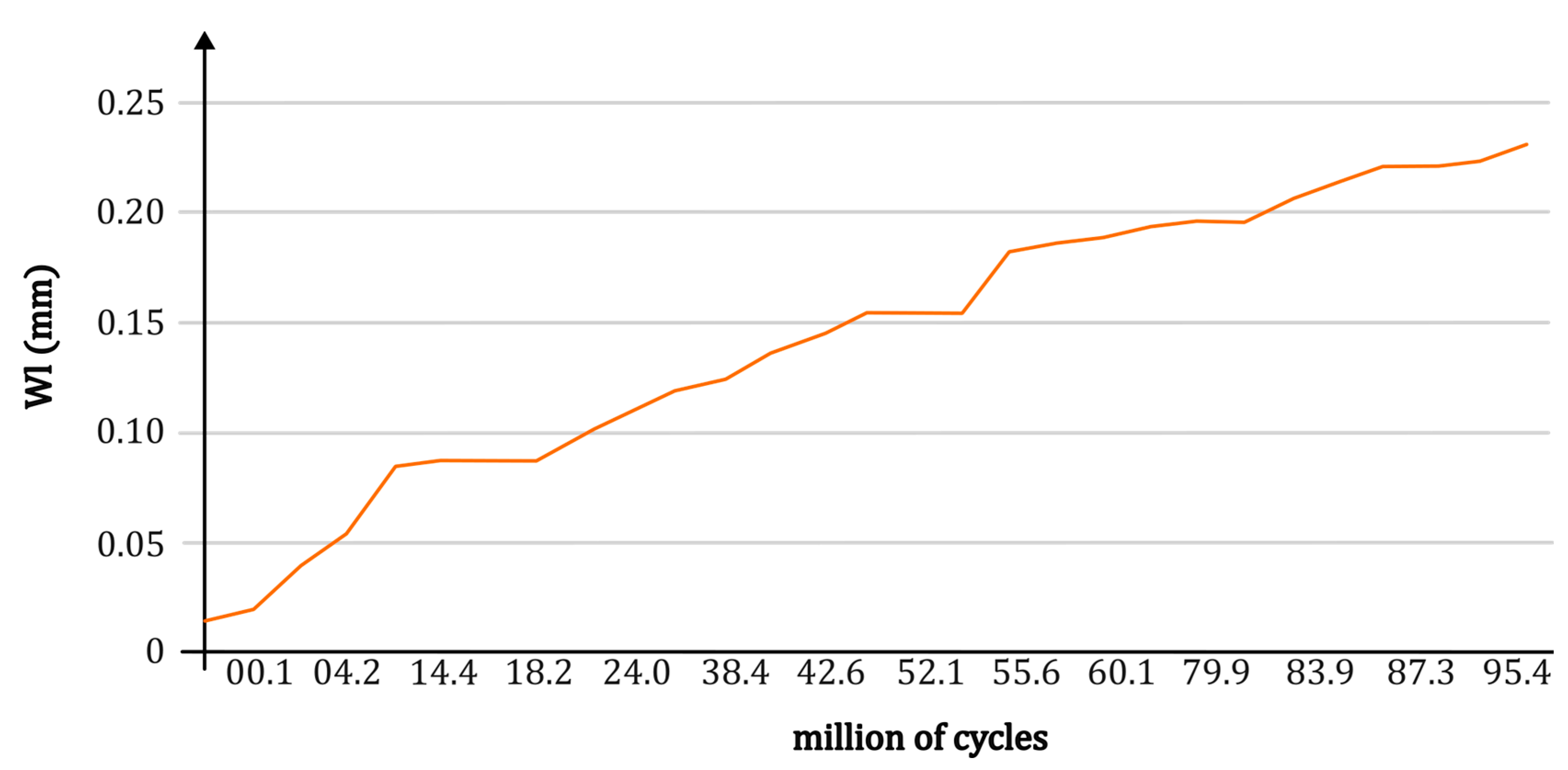
Wear on the right flank after a few million cycles is visible. The efficiency of the transmission was still good at the end of the test, showing the efficiency of the bench. In
Figure 11, the graph shows the wear data retrieved with post-processing from Equation (4) as a function of the cycles completed. For this, a correction factor of 7/6 was applied to the equation, considering that only
of the gears (nominal thickness
) was in contact during the test. Two identical plastic gears of module
, primitive diameter
(see 9 in
Figure 2), number of teeth
, with inclination
, at
and constant torque of
were tested.
The present challenge lies in achieving precise wear measurements that today require the cessation of the test for subsequent analysis. To address this, a system has been devised to automatically halt the test at predefined intervals using a tachometer, with the potential for a similar approach utilizing a position sensor. In the pursuit of enhanced visibility, modifications have been implemented to allow direct observation of the wheels during testing outside the climatic chamber. However, challenges persist within the chamber, posing ongoing considerations for further refinement.
The preliminary test conducted showed us good agreement between the wear calculated through Equation (4) and the wear retrieved by post-processing of images or by a coordinate-measuring machine equipped with a micro metrology probe.
5. Conclusions
In conclusion, our research aimed to tackle the complex challenges associated with the wear analysis of reinforced polymer gear wheels. The limited availability of comprehensive literature on the wear behavior of these materials underscores the necessity for focused investigations and advanced testing methodologies. Our focus on glass fiber-reinforced self-lubricating polymer gearwheels, particularly under non-conventional temperature conditions, led to the development of a specialized test bench.
Starting with a comprehensive exploration of wear phenomena and challenges associated with existing standards, we adapted and improved the basic test bench design.
Our study draws inspiration from Mao’s work, providing a detailed exposition of his test bench to set the stage for our advancements. The adaptations for climatic chamber utilization, including geometrical reconfiguration, drive system redesign, and continuous displacement measurements at high temperatures, showcase our commitment to real-world applicability.
While our preliminary test results remain confidential, they validate the efficacy of our testing setup in evaluating wear under diverse conditions. Challenges persist in achieving precise in situ wear measurements, leading to the development of a system to automatically halt tests for subsequent analysis.

 ,
, 


