1. Introduction
The automotive industry is a precursor to numerous technologies, since one of its main pillars is innovation. In fact, the market is constantly demanding more differentiated products at an increasingly competitive price [
1]. Thus, the automotive industry needs to overcome the challenges induced by its customers and maintain competitiveness, which normally requires high levels of automation [
2]. In addition, due to the growing trend towards product customization, the quantities to be produced in each batch decrease, posing new challenges in production management [
3,
4] and in the design of new equipment. Thus, the equipment must be increasingly flexible, contributing in this way to the minimization of setup times, which can have a significant impact on the dimensioning of the batches to be produced, affecting the competitiveness of the product [
5]. Science and engineering are particularly prominent in this context.
Automation can be, essentially, of three types: fixed automation, flexible automation, and programmable automation [
6]. Fixed automation is mainly used for mass production of the same product. Flexible automation is used for families of similar products, where a relatively short setup allows a switch from one product to another within the same family. Programmable automation is the most advanced and also the most flexible, but also the most expensive to implement, and the one that best integrates the principles of smart manufacturing [
7,
8,
9]. In the last few decades, research has been focused mainly on flexible and programmable automation, but there have also been studies in fixed automation [
2,
6,
7,
8,
9].
Particularly interesting are the automation solutions that solve the problems implying low costs. This is the main objective of
autonomation or Jidoka, a concept which is one of the Toyota Production System (TPS) pillars. This important concept, as well as JIT production, allowed
lean operations, i.e., operations doing more with less—less stock, less human effort [
10], less of everything [
11,
12]. These operations are behind the TPS success and have been extensively applied in companies around the world under the occidental name of lean thinking [
13]. This management philosophy reduces cost and increases productivity by eliminating waste [
14,
15,
16] and having a great impact on the financial performance of manufacturing companies [
17,
18]. Among the seven most-known wastes, are the ones related to irregularity and the overburdening of people and machines and these needing to be eliminated [
19]. One of the methodologies that focuses on improving productivity, by reducing wastes and optimizing processes is the lean-six sigma method [
20].
In this context, the presented work aims to automate the feeding of bent wires to a plastic injection machine to reduce human intervention in the process, as well as extracting the over-injected product. Operators need to perform the same working cycle several times a day, being subject to fatigue and, as a result, make mistakes in feeding the wires to the system, causing quality problems. The challenge of this work was to design an automated system to overcome this problem, and increase the productivity and competitiveness of this process, also respecting restrictions in terms of space and budget. This work proposes a set of novel devices for automating systems that can be connected to existing over-injection molding machines (or similar), improving the handling of the products, cutting the associated human labor, and using low resources, providing a low-cost solution able to be installed as an upgrade of already-existent machines.
This paper is divided into six main sections beyond the current one.
Section 2 provides a wide theoretical background,
Section 3 describes the methodology used,
Section 4 depicts the results,
Section 5 discusses the results achieved, and
Section 6 highlights the main outcomes and transferrable knowledge.
2. Background
Costa et al. [
2] developed a new equipment concept for the assembly of shafts for driving car windshield wipers that, through various mechanical devices and some flexible automation, allowed quality and reproducibility problems detected in previously designed equipment to be solved, guaranteeing parts that were completely acceptable. In addition, the equipment presents high flexibility, being able to distinguish between different parts of the same family in the parts’ supply process. The return on investment is just two years and guarantees a cycle time equal to or less than that achieved with the previous equipment. The labor associated with the equipment is now restricted to feeding the equipment and removing assemblies. Using an indexed table and several flexible automated systems, Nunes et al. [
7] also designed a system capable of eliminating the problems of incorrect assembly existing in the manual assembly of small systems used in automobile windshield wipers, due to the fatigue of workers in repetitive operations of low cycle time. The system also presented high flexibility, allowing the assembly of more than twenty sets of the same family of products. Moreira et al. [
8] developed a flexible system for the assembly of several types of Bowden cables of the same family, allowing the manufacturing cycle time to be shortened, but mainly eliminating the intermediate stocks existing between the different operations. Costa et al. [
9], based on a product identical to that used in the work of Nunes et al. [
7], developed competently automated and programmable equipment, which allowed the feeding of components, their assembly in jigs suitable for each product of the same family, and the assembly and control through a very innovative concept, practically without any human intervention. Santos et al. [
21] used state-of-the-art automated systems to upgrade equipment to produce vehicle tire components, greatly increasing the accuracy of the equipment, improving the final product quality, but essentially drastically reducing downtime due to breakdown of the equipment (−62%). Santos et al. [
22] developed an automatic system for the transport of conduits (sub-product) inside production equipment, significantly improving the process and eliminating the problems of lack of reliability in previously used solutions. The new automatic system developed has saved 97% of the time previously required for the setup, while contributing in a very positive way to the drastic reduction in equipment breakdowns. With a view to solving sheet metal plate deformation problems in the final part of the cutting process of thin metal sheets in guillotines, Araújo et al. [
23] developed a completely automated system, capable of being assembled on new guillotines or others already in operation (upgrade) which, through an innovative system of support of the plate during the cutting process, prevents the plate from tending to bend under its own weight at the end of the cut.
The number of plastic and composite parts present in cars has increased considerably in recent decades, and the production optimization of these components has been the main target of many researchers. Automation and automatic systems play an important role in polymeric part production, increasing the productivity and cost-effectiveness of the production process [
24]. Currently, addictive manufacturing of polymers is moving more and more towards manufacturing applications, allowing more competitive parts and a more flexible process [
25]. However, even traditional polymer parts for the automotive industry have been the target of some studies trying to improve their mechanical properties [
26] by redesigning the manufacturing process itself, as presented by Beran et al. [
27]. In the current work, the part remains the same, but the process is improved through automated systems.
The evolution of automatic production or assembly systems includes robotics, through what is called programmable automation, playing a very important role in the recent automotive manufacturing industry [
28,
29], as the implementation of robotics and automation allows for an increase in productivity and process efficiency, with many of the manual processes being replaced by alternatives that involve automation [
30]. Barbosa et al. [
31] developed a new completely automated concept of feeding parts and tool in the milling process, which allows the exchange of products and tools in a perfectly automated way, and according to instructions received from a central computerized system, thus allowing total flexibility of the manufacturing process. Regarding the use of robots in the production of automotive parts, Yin et al. [
32] proposed a flexible punching system based on industrial robots to produce automotive panels, combining a special punching plier and industrial robots. The proposed system is modular and more flexible and efficient, effectively reducing the production cost of automotive panels. Another recent study on the use of robotic systems in the manufacturing industry [
33], focused on the improvement of robotic systems for the production and assembly of automotive parts. In this study, the authors present an algorithm capable of determining the best layout and assembly order for robotic production systems being implemented and validated for large-scale industrial scenarios. There have also been some recent studies conducted on the use of human–robot collaborative assembly lines/cells for automotive parts. These collaboration workstations can bring many advantages, benefiting from the capabilities and skills of both the industrial robots and human workers. Thus, efforts are being made in the improvement of worker safety of these stations [
34] and the development of robotic systems, specifically developed for the facilitation of human interaction with these industrial robots [
35].
Car seats are made of a series of components. New trends point to the mating wires with injected plastic tapes, with a view to reducing the weight of this product, saving energy (a natural resource) and reducing pollution [
36,
37,
38,
39]. Thus, nowadays, the manufacturing sequence of some car seat components goes through the cutting and bending of the wires, then these go to the plastic injection machine, where the wires are aggregated through injected plastic tapes. Cushions and suspension mats are structures made of metallic wire and plastic connections, which are connected to the structures of the car seats and support the foams that provide the comfort of these seats. Magalhães et al. [
40] developed an automatic system that allows the collection, orientation identification, positioning, control, and sorting of bent wires used in cushions and suspension mats. This system has significantly improved the interconnection between the cutting and bending operations of these wires, as well as their feeding to plastic over-injection machines. Silva et al. [
41] developed an automatic system for the last stages of suspension mat production and control. Through automation and robotics, these components started to be automatically controlled after the last manufacturing phase, and to be packaged according to customer instructions, also automatically, thus allowing greater process reliability and shorter cycle time. In the car seat component manufacturing process described above, the part of the process that still needs to be automated and where a strong human component is still used is the feeding of bent wires to the plastic over-injection machine [
42], as well as the extraction of the over-injected suspension mat components (bent wires already coated with polymer). That is the main subject of this work—designing a novel automated system comprising a set of devices able to occupy an area as small as possible, requiring a reduced budget, and able to automatically provide the right number of wires to a gripper in the right position, and be able to extract the over-injected wires after the over-injection process, placing the wires into the corresponding conveyor.
3. Materials and Methods
The research carried out through this work was based on an industrial need, which was taken as a starting point for the development of a novel solution that could be transferable to other similar situations. At the same time, it was necessary to increase productivity, reduce labor, and find low-cost solutions that are flexible enough to be adopted for a given family of products usually manufactured with the same equipment. Regarding the space available around each side of the equipment, the use of robotics was discarded.
Thus, the strategy of this work was to create a set of devices which would consist of a storage system placed next to the injection machine that would provide six wires already bent in the correct position for the gripper to catch, and a rotating device where this gripper would be connected, thus completing the tasks of positioning and collecting these wires and placing them into the mold and, after the injection process has been occurred, collecting the wires already over-injected and placing them into the conveyor belt. The automatic system to be connected to the over-injection machine needed to occupy a small area and use essentially conventional automation based on pneumatics. The novelty of this work was to provide a flexible set of devices to operate in plastic injection over-molding machines, that were different from the conventional robotics associated with injection machines, that were low-cost, and that would be able to be installed as an update for already-existing machines, increasing the productivity and competitiveness of products with very low added-value and occupying just part of the restrict space between injection machines. This solution is completely different to a robotic solution, as it uses a novel wire-feeding system for the bent wires and a rotary pneumatic arm for extracting the over-molded wires, using the same gripper. The set of devices developed can also be adjusted to other needs, following the same principles.
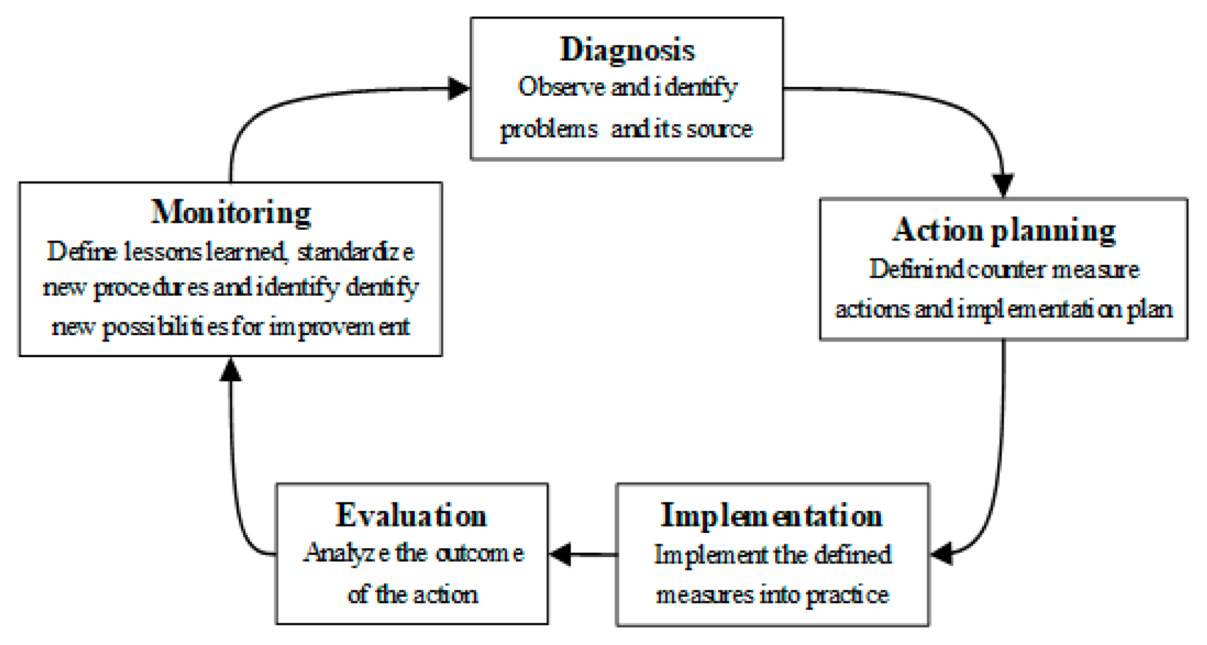
With a view to developing a solution that would achieve the intended purposes, that is, finding a solution capable of fixing the wires and, after injection, removing the complete product from the mold, for a wide family of similar, but different products, the action–research methodology was used [
43]. This methodology allows changes to be made (actions), and from the solutions, one finds lessons learned that can be transferable to other situations in which these solutions may also be applied, that is, transferable knowledge (research). This methodology has several approaches. For this work, a cycle with only five steps presented initially by Susman & Evered [
43] was selected, as illustrated in
Figure 1. Thus, the cycle begins with an observation phase of the problem to be solved and of the existing conditions, followed by an action-planning phase, which, in this case, translates into a solution to be implemented. The third phase is essentially the implementation of the solution, while the fourth phase is essentially based on the evaluation of the solution. The fifth and final phase concerns the monitoring of the implemented concept, as well as the taking of lessons learned, which can be transferable in the form of knowledge to solve similar problems.
In the specific context of this work, the different phases previously described and depicted in
Figure 1 can be translated into concrete actions, as described in
Table 1.
The diagnostic phase has already been lightly mentioned previously in this work, but it will also be dissected in this section. The phases of action planning, implementation, and evaluation will be described in detail in the Results section, while the last phase will be described in the Discussion and Conclusions.
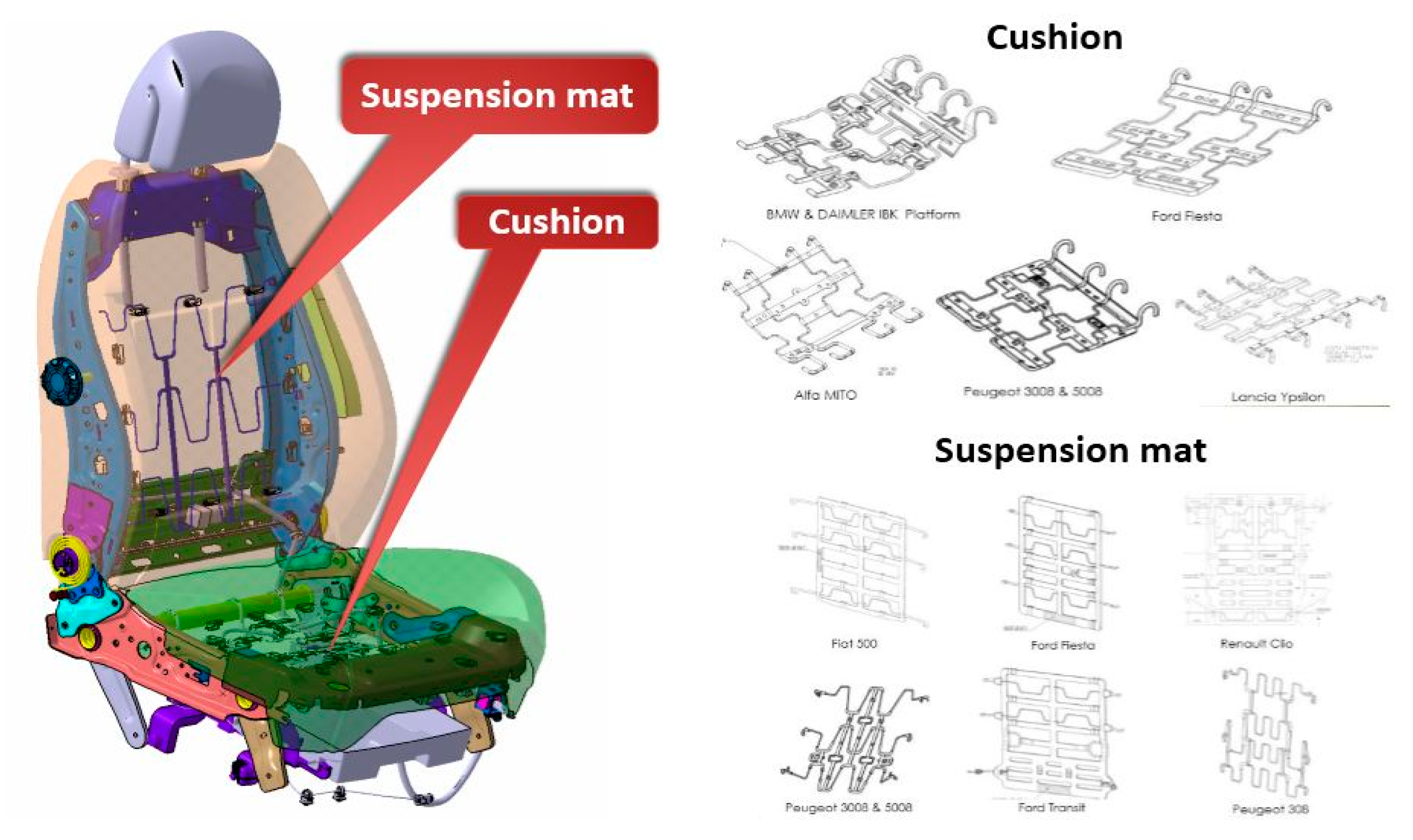
Starting by the diagnosis, the problem posed as the basis of this work had a strong industrial engineering component, which required a strong collaboration with mechanical engineering. The main problems were the need to increase the productivity of plastic over-injection machines and the competitiveness of the products to be incorporated in car seats, giving rise to a product usually called as cushion or suspension mat, depending on whether it is placed on the seat base or on the seat back, respectively (
Figure 2).
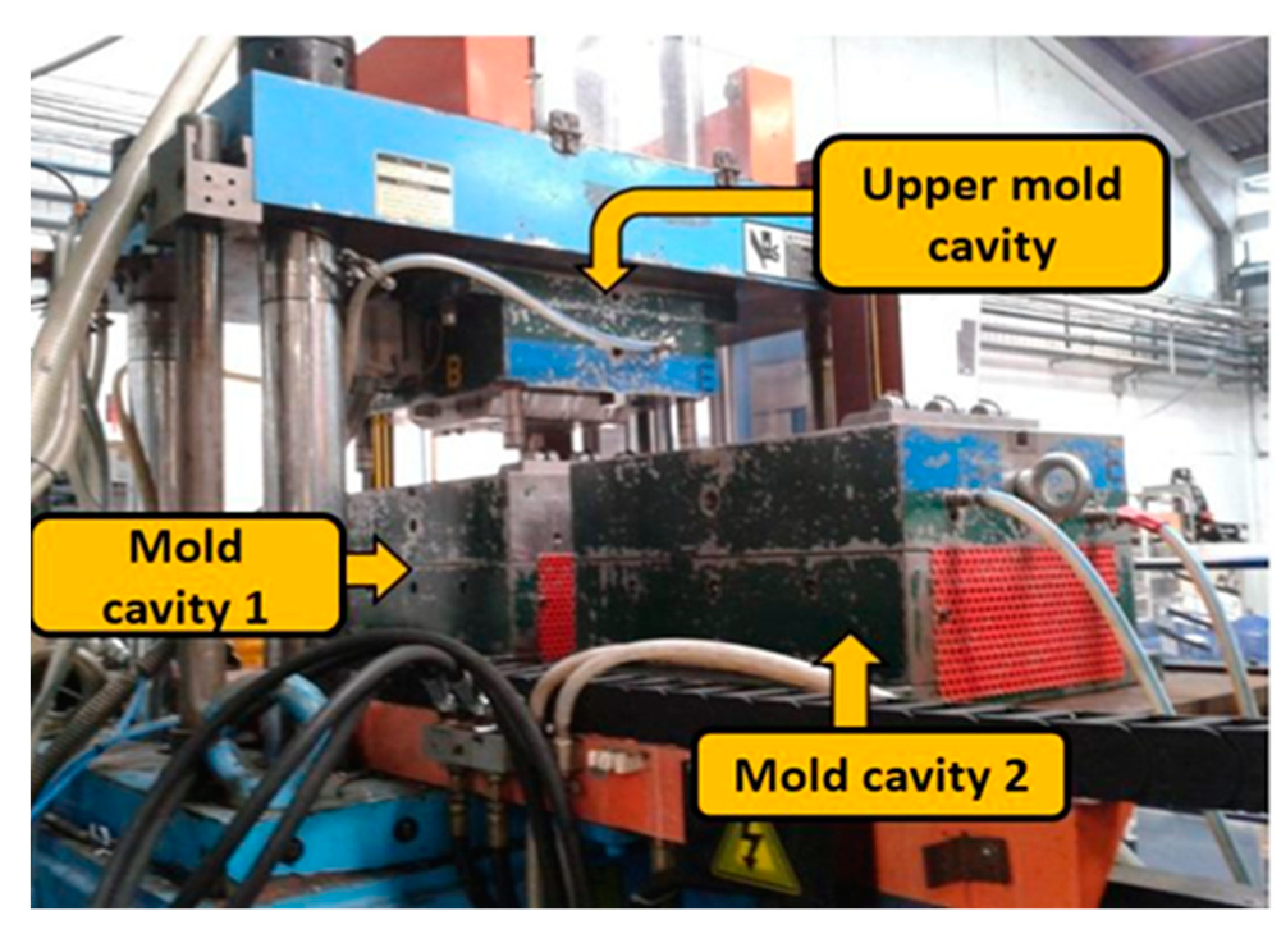
Plastic over-injection machines work with one mold and a half-mold, i.e., the parting plane is horizontal, the mold opens under a vertical axis, the upper part is single (male), while the lower part (female) is twinned. These twinned lower parts of the mold are assembled in a sliding worktable. Thus, while the machine is over-injecting in one of the lower half-molds, the other lower half-mold is being fed with wires or is being unloaded. This can be seen in
Figure 3.
This project was intended to make the wire loading and unloading processes automated, however this would require action on both sides of the machine. Due to space restrictions, it is not possible to load and unload the wires from both sides of each machine with a robotic system because the amplitude of movements is too large and the space available is not enough. Moreover, to load the mold with wires it is necessary to have a proper device, which is charged with a batch of bent wires and a drawer which provides the right number of wires in the right position. Furthermore, a rotary manipulator is used to promote the movements in the X, Y, and Z axes. However, again due to lack of space, just one rotary manipulator is not enough to cover all the working area. Thus, the devices need to be replicated on both sides of the machine, where the lower molds stop after the over-injection process.
Given the requirements of this project, which aimed to provide almost 100% automation of the operations around plastic over-injection machines, the operator only needs to feed the already-bent wires into the wire-feeding device, and control whether the entire sequence of operations is duly performed by two injection machines and the new devices placed around them, for process automation. Because the operator tasks now consist of feeding the wires to the device and controlling the functioning machines, one operator is enough to control two machines. For the extraction of the already over-injected parts, it was necessary to design an automatic system that allowed the parts to be extracted and which was connected to the rotary manipulator—a special gripper. Extraction is the simplest task, since all the wires are properly positioned in the lower half-mold and the gripper will have the reference of the place where it should be found, so it is only necessary to pick-up the wires already over-injected and drop them in the proper place, the conveyor belt, which is common to both sides of the injection machine. It is also required that this extraction be directed to a conveyor belt that moves the parts dropped by the gripper to a container. Thus, in a first approach, it was necessary to create a system with movement in the X, Y, and Z axes, capable of lowering in Z and grabbing the wires inside the mold, lifting to the horizontal movement position, and moving in Y to dump the part on the conveyor belt that will move the over-injected wires to the container. This was the concept that needed to be designed and tested. The next task of the rotary manipulator is moving to the drawer, where the fresh wires are ready to be picked up and moved to the cavities of the mold for the next production cycle.
Figure 2, shows different configurations of cushions and suspension mats, as well as their position in the car seat. The diversity of models presented in
Figure 2 (right) is only indicative, since each car model has at least one model of cushion and suspension mat, but the increasing customization of vehicles has meant that each car model may need different configurations. This need has direct implications on the requirements established for the concept to be developed, because the gripper for different wires can be different, depending on the similarities (or not) between the wires’ models.
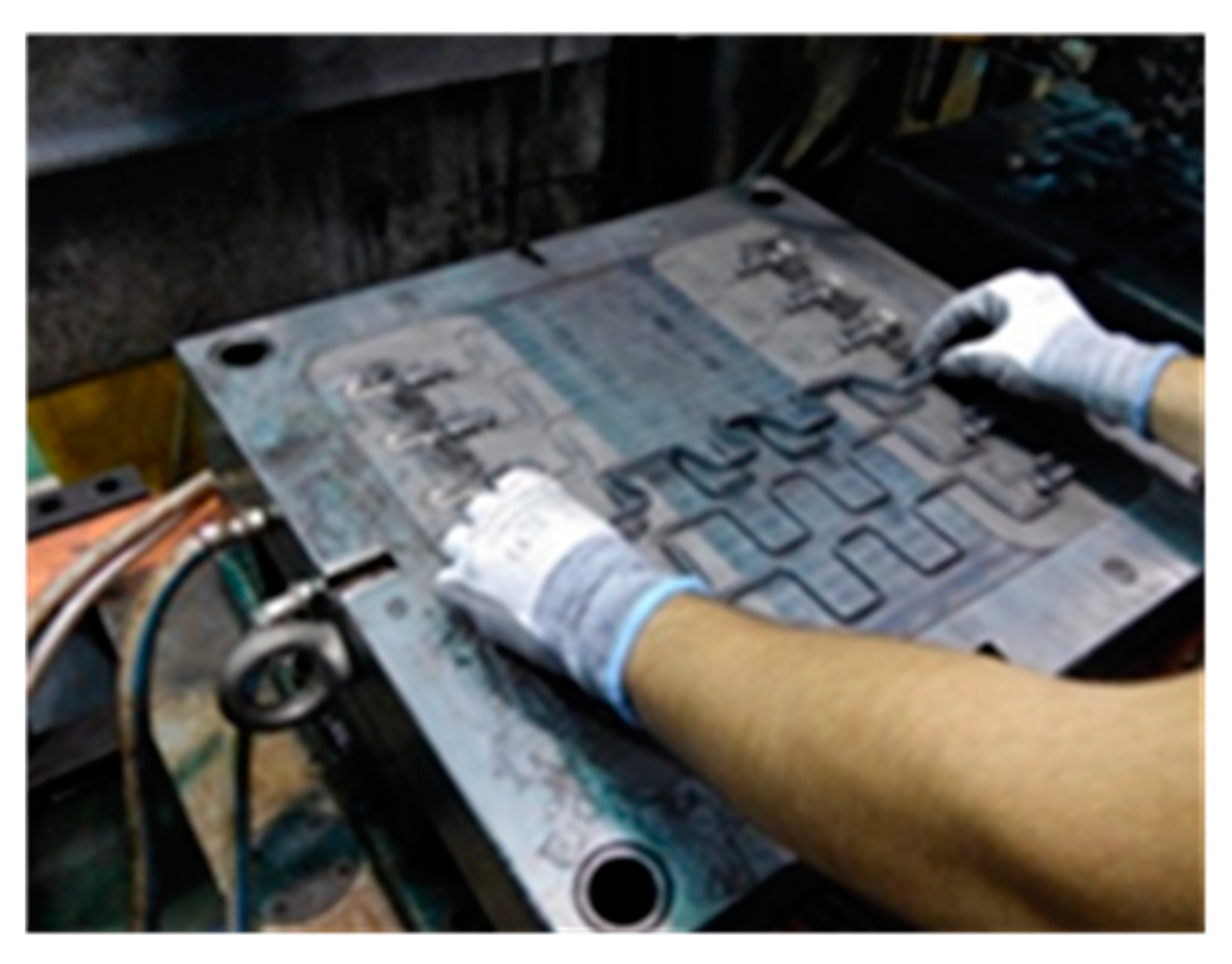
Still in the diagnostic phase, observations were made about the wire-feeding operation into the mold. Given the diversity of existing models and the complexity of the shape of some models (3D-shaped wires), 2D bent wires were selected. This was also the best option because the way the 3D bent wires arrive at the over-injection machine is not properly prepared, so it requires extra effort to condition the position of the wires so that the robot can pick them up and place them in the proper area of the mold. Moreover, extra space needs to be created around the machines to allow for robotic solutions, which is out of the scope of this work. Thus, the feeding operation of 2D bent wires needs to be automated without the use of robotics. The previous manual operation of feeding the wire molds can be seen in
Figure 4, showing a simple wire model (2D wire). This is one of the tasks that needs to be replaced by automatic systems.
Thus, this work comprised the automation of two tasks: the feeding operation of 2D bent wires and corresponding extraction operation, and the extraction of the over-molded wires after the over-injection process.
4. Results
After the diagnosis stage was finished, it became necessary to act, through the idealization of solutions that could solve the feeding and extraction problems. The positioning of the wires was very close into the mold. This is a common situation when the assembly is manual. To save space a machine with a smaller table is required or over-injecting more parts per cycle is allowed. Bearing in mind that this situation cannot be solved by making a new mold, and because the same situation is common to other molds, a solution was conceived in which the feeding was carried out in two stages. Since the capacity of the mold was six-wire, to be over-injected at a time, the feed could be carried out twice, three wires at a time. The number of wires to be over-injected is not directly related to the wires used in each car seat, but to the space available on the surface mold. The wires were treated in this work as single parts. The idea is expressed in
Figure 5.
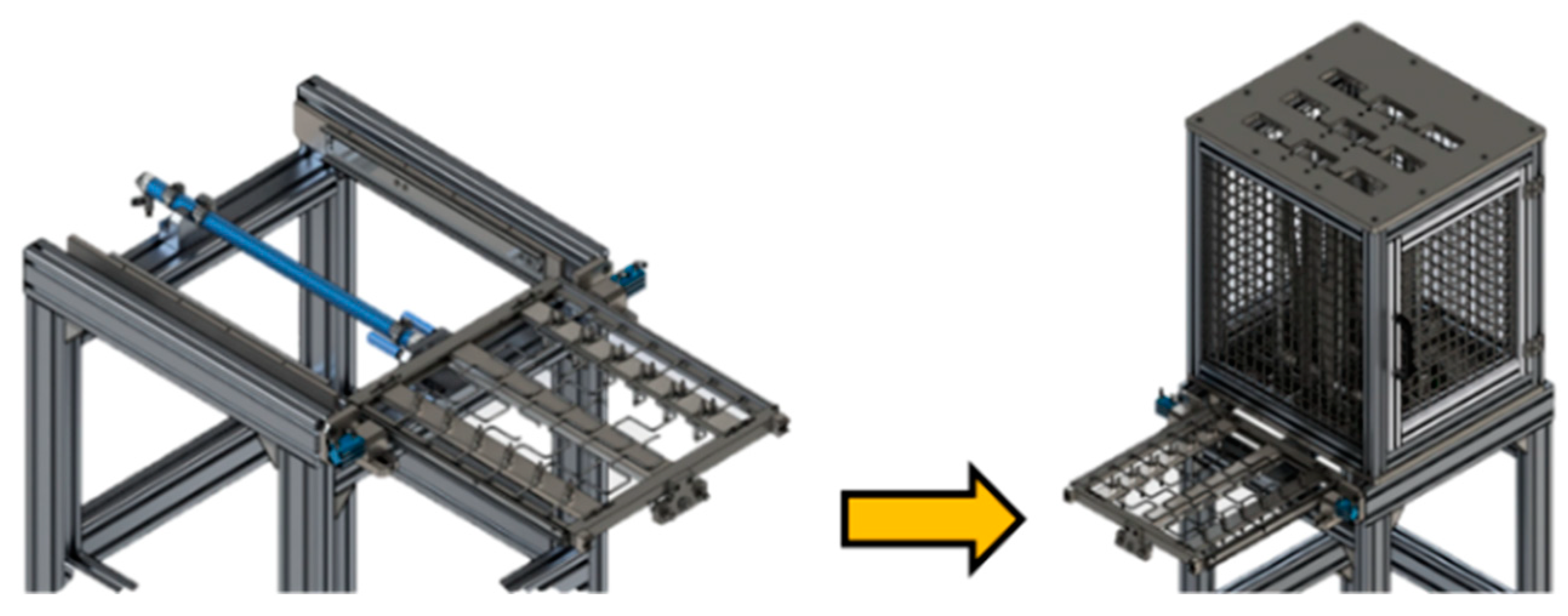
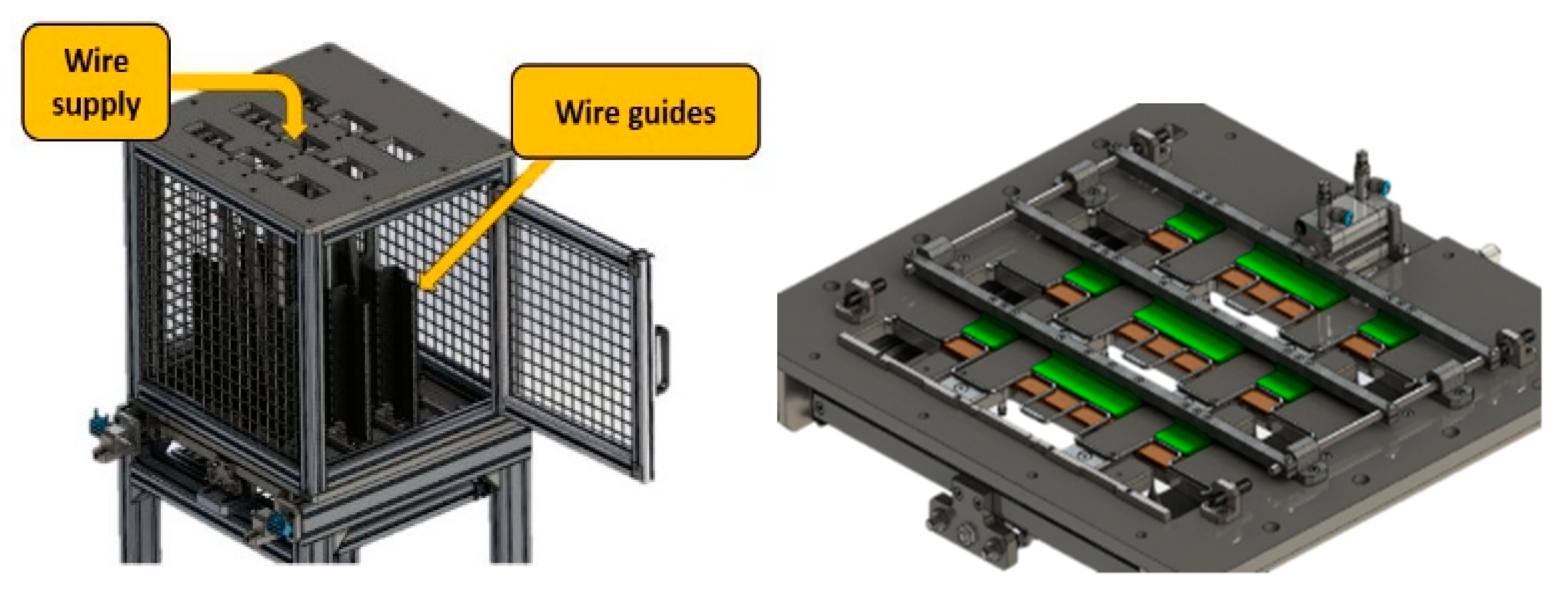
Considering that the wires are supplied by a system external to the injection machine, it was necessary to create a system that could store the wires already properly ordered, so that they could be supplied to the mold by a gripper. For this, a supply tower was created, which was to be fed manually, through previously formed wires that were transported from the wire bending equipment to the storage tower. This storage tower should have three stacks, that is, the same number of stacks as the number of wires that are fed to the system each time. As previously mentioned, three wires are provided at a time, in two stages, making up the total of six wires required for each supply. The stacks are far enough apart that, in the second phase, wires are deposited at the intervals left vacant in the first phase, as shown in
Figure 5. Underneath the wire storage tower, a drawer with horizontal movement is required, which can make three stops: (a) in the first stop, it receives the first group of three wires, (b) in the second stop, it receives the second group three wires, and (c) at the last stop, it is in the place necessary for a gripper to come and pick up the six wires (
Figure 6).
Between the wire storage tower and the drawer, there is an electromechanical system that only allows one wire from each stack to pass in each complete cycle of movement of the drawer, and only when it is in its rearmost position, that is, completely below of the storage tower. Details of this electromechanical system can be seen in
Figure 7.
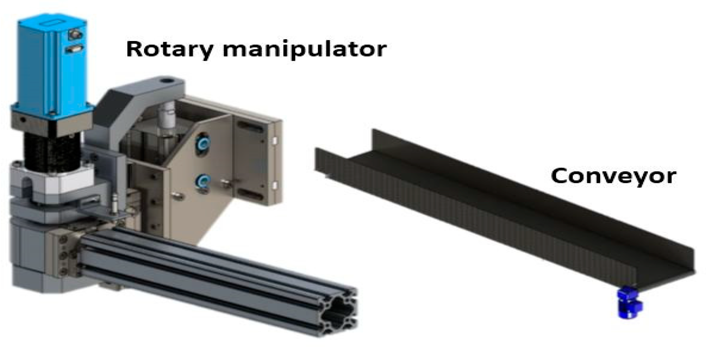
As the storage and feeding system described above will function as an external system to the injection machine, it will be positioned laterally, implying that the gripper that will descend to the drawer and collect the six wires must also be equipped with a rotation movement. Thus, a rotary manipulator needs to be added to the set of devices considered in this project, allowing for the performance of the needed movements in the restricted space available. Due do this space restriction, the rotary manipulator seems to be the best option, because it can be connected to the machine and acts as needed along the lower half-mold, the wires feeding system, and the conveyor belt. In addition, it is intended that each gripper can feed the mold with wires, making its tamping inside the mold, for correct fixing of them inside the mold (they work as inserts), but also being able to extract them after over-injection of plastic at its ends. Therefore, a rotary manipulator was designed, which, through rotation, can switch between three different positions: (a) collect the wires in the drawer, (b) feed the wires and wedge them inside the lower half-mold, and (c) extract the over-injected wires and deposit them on a conveyor belt placed on the same or opposite side of the machine, as can be seen in
Figure 8.
Moreover, the strategy to be provided for the wire pick-up in the drawer must be fully consistent with the strategy of extracting the wires already over-injected from inside the mold. The relative position of the wires among them needs to remain the same as before, i.e., the gripper responsible for picking up the wires from the drawer is the same as the one responsible for the extraction of the wires already over-injected with plastic. Thus, two parallel gripper systems were created, each one acting in different sides of the machine, because each lower half-mold needs to be loaded and unloaded in opposite sides of the machine. Thus, each rotary manipulator can be connected to each side where the lower half-molds are made accessible to carry out the wire loading and unloading operations.
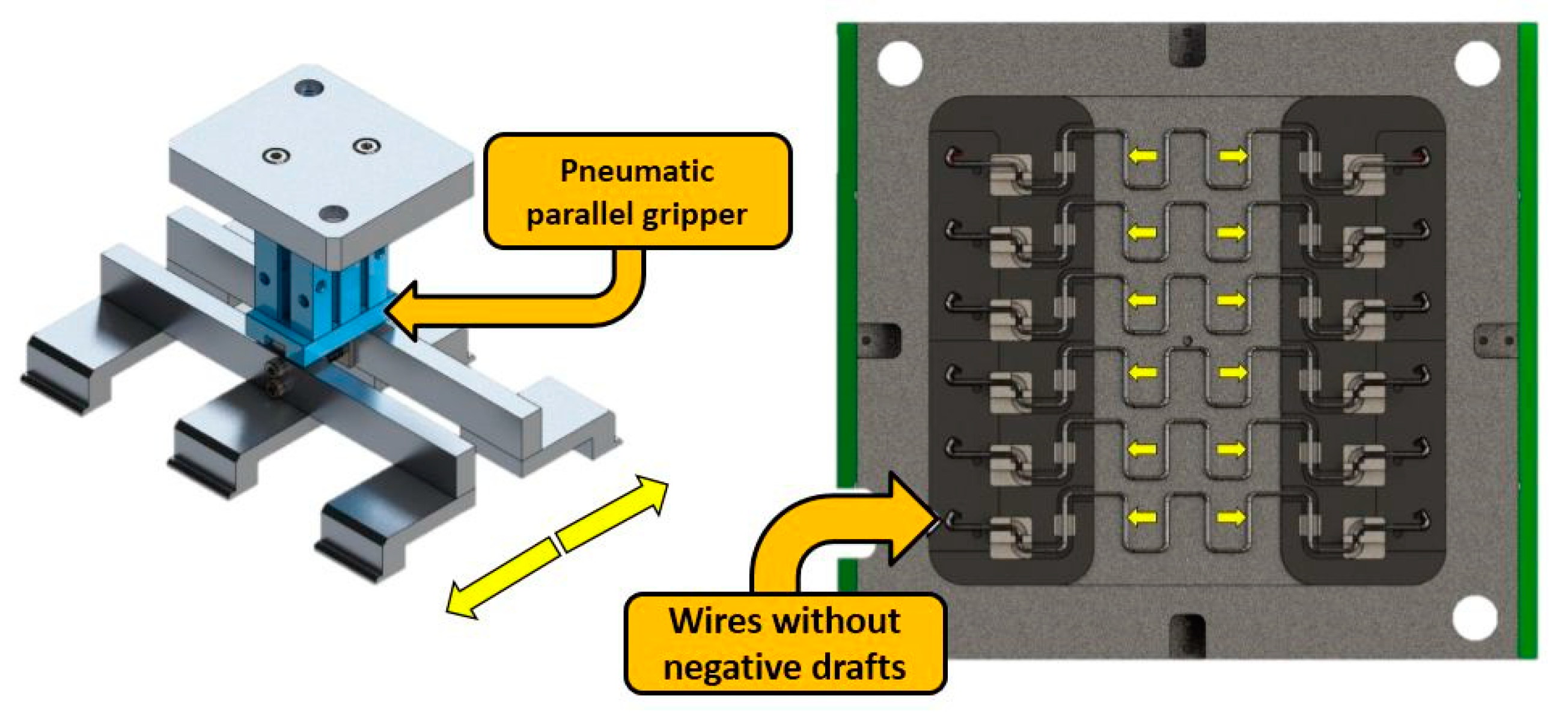
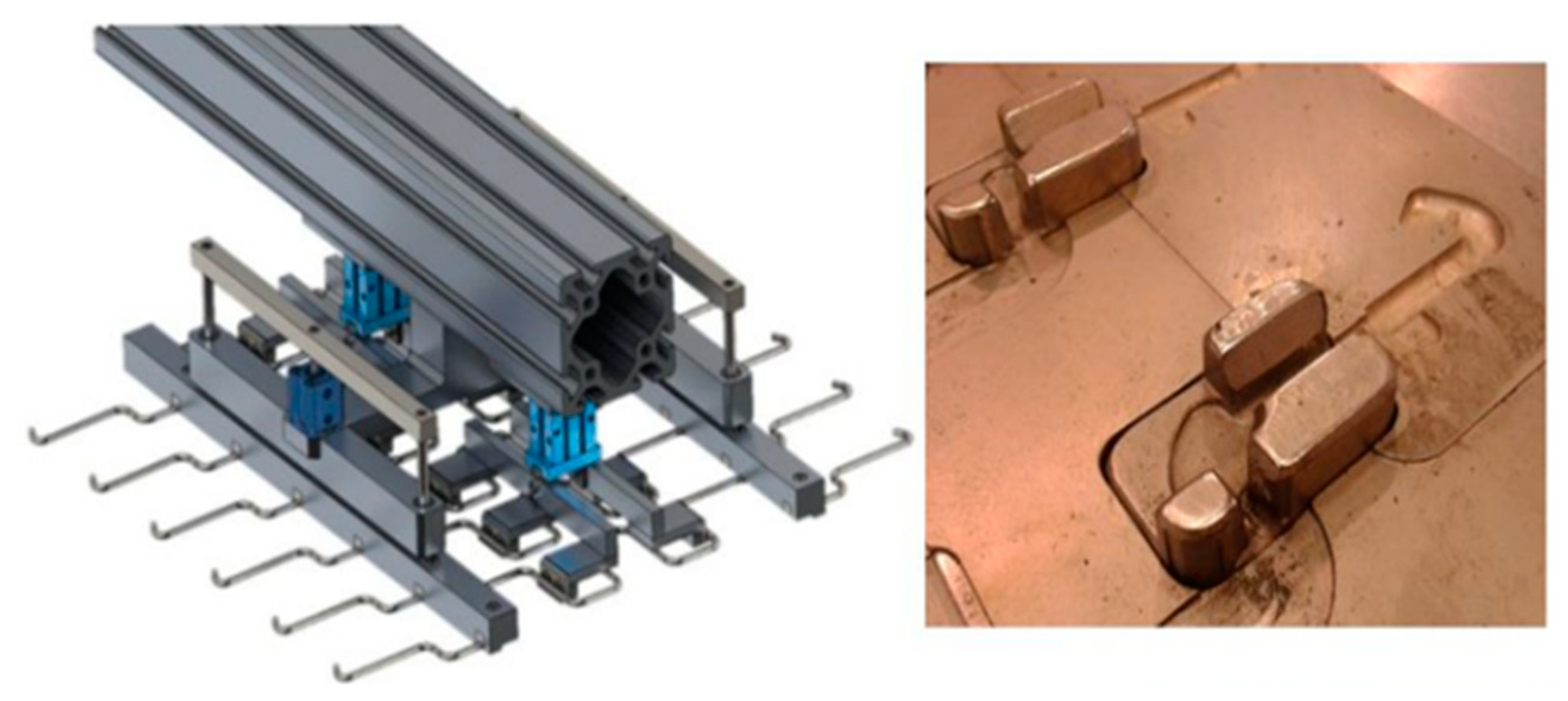
Figure 9 shows only a part of the system (responsible for handling three wires), as well as the places in the mold where two of these grippers will act (yellow marks), to collect all the wires at once.
Figure 10 shows, on the right, the gripper already complete, as it should be mounted on the rotary manipulator shown in
Figure 8. It should be noted that all these grippers take their own shape depending on the geometry of the wires, their relative distance, and the place where it becomes more advantageous to manipulate them. Thus, each wire geometry will involve its own gripper, which is subject to a setup process whenever the machine changes the product to be manufactured, thus, the connecting system should be standardized to make this task easier and less time-consuming.
In
Figure 10, on the right, the locations of the mold where the wires must fit, so that they are properly positioned inside the mold can be seen, ensuring a virtually constant thickness of plastic all around the tips of these wires. When placing the wires into the mold, the grippers must be programed to open, and leave drop the wires in the right position. After that, they must close, and a light downward vertical pressure must be applied to the wires in the right place, ensuring that the wires fit perfectly into the proper locations, not posing a threat to the closing of the mold or quality problems in the over-injection operation. When the previous injection cycle is finished, the injection machine opens the mold and the double lower part of the mold moves, exposing the part already over-injected to one of the grippers on one side of the machine. Meanwhile, the half part of the mold where the wires are already fed slides under the upper part of the mold, allowing it to close and to start a new injection cycle.
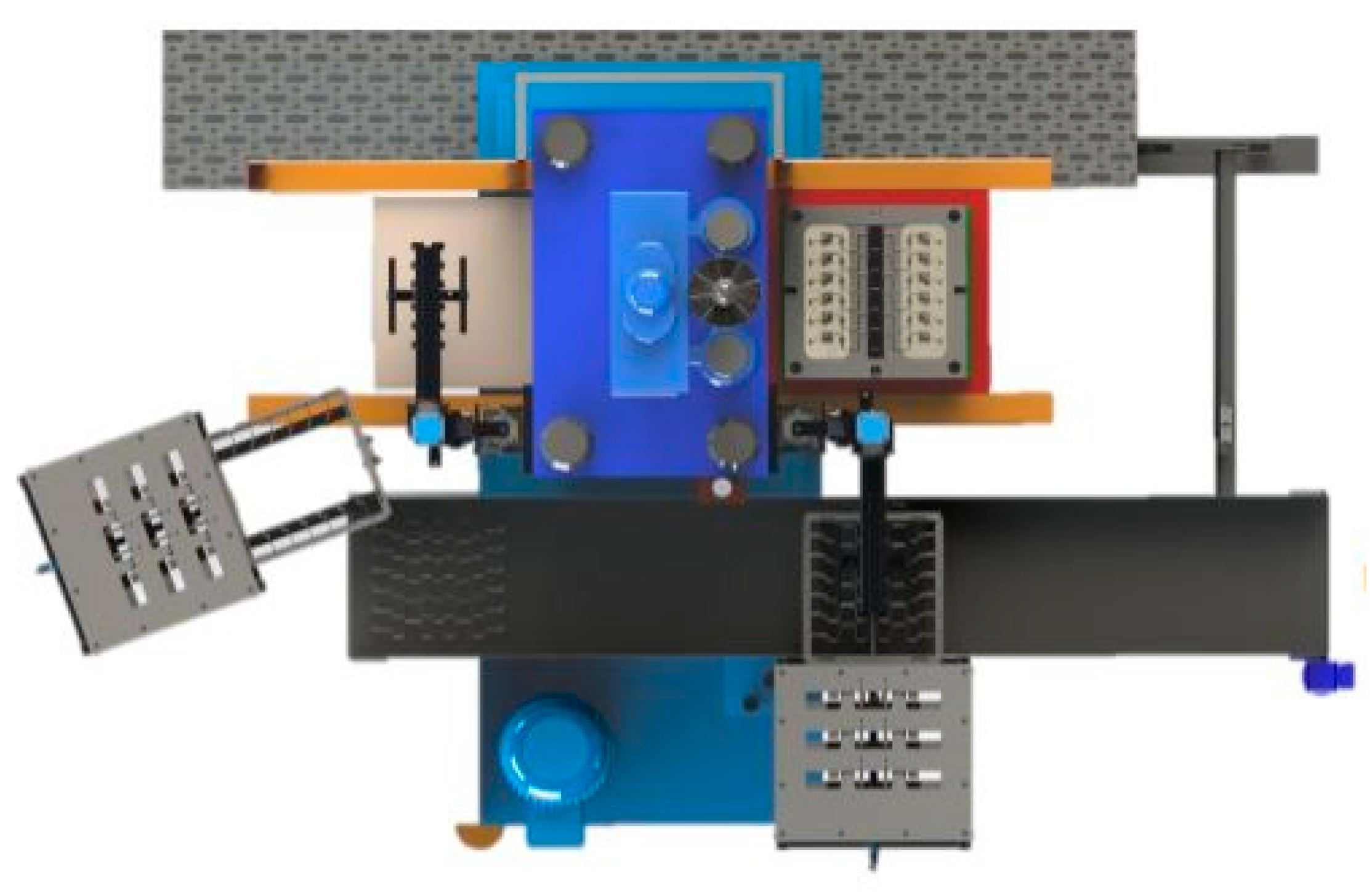
It should be clear that each injection machine needs two grippers, as shown in
Figure 11 (represented in black color). This need arises from the lack of space for a wider structure, as well as the need for joint actions over time, because when a gripper finishes extracting the newly over-injected part, the gripper will have to immediately look for the drawer to supply wires for the next cycle, while the other gripper must be empty, ready to grab the next over-injected part. The position of the two grippers around each machine can be seen in
Figure 11, where the left-hand gripper is waiting for the end of the injection cycle and for the lower part of the mold to slide to its resting position, to collect the over-injected part, while the right-hand gripper is depositing the previously over-injected part on the conveyor belt. Then the wire supply drawer opens and the gripper collects the six wires already in position to supply the half-mold, which is empty, that is, from where the over-injected part came out. In the meantime, a new injection cycle is underway, and the other gripper will be able to pick up the part finished to be over-injected.
Thus, the cycle performed by each gripper can be described as follows:
- (a)
The gripper waits for the end of the over-injection cycle and movement of the lower part of the mold. When the over-injection cycle ends, the half-mold slides and exposes the over-injected part to the gripper.
- (b)
The gripper moves downwards and grabs the part from inside the half-mold, extracting it. It goes up and rotates onto the conveyor belt, where it descends vertically and drops the part.
- (c)
In the meantime, the wire-feeding system performs the first two actions, allowing the correct positioning of the six wires in the drawer. After that, the drawer moves to its final position, completely open, to facilitate the collection of the wires by the gripper.
- (d)
The gripper takes the six wires already properly positioned, moves vertically and rotates until it is over the half-mold that is empty and in the necessary position to be supplied with wires.
- (e)
The gripper descends vertically until almost touching the mold, and drops the wires in their respective positions.
- (f)
The jaws that hold the wires close, and the gripper makes a slight downward movement, so that the ends of the jaws press the wires into the chamfers created for the purpose.
- (g)
The gripper rises vertically and will wait for the half-mold to move into the injection machine. The over-injection process takes place and slides again to the position where the part is collected by the gripper and the subsequent feeding of new wires is made, starting a new cycle.
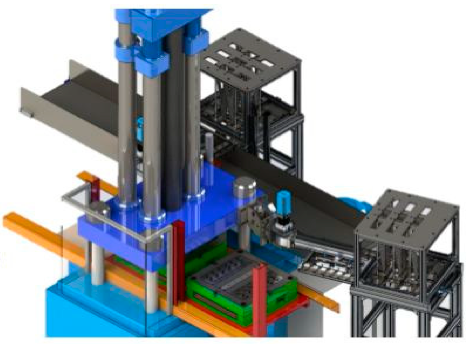
Figure 12 shows a 3D perspective of the system previously shown in 2D in
Figure 11. As can be seen, the occupied space by these new systems (power towers and grippers) is quite reduced, being compatible with companies where the cost of occupied space is high and where the machines need to be very close to each other.
It should also be noted that all the main devices necessary for this system, namely the treadmill and the main arms of the gripper, were recovered from systems previously put out of service in the company, thus contributing to the system reuse policy, with clear benefits for the environment and the sustainability of the process [
39,
44].
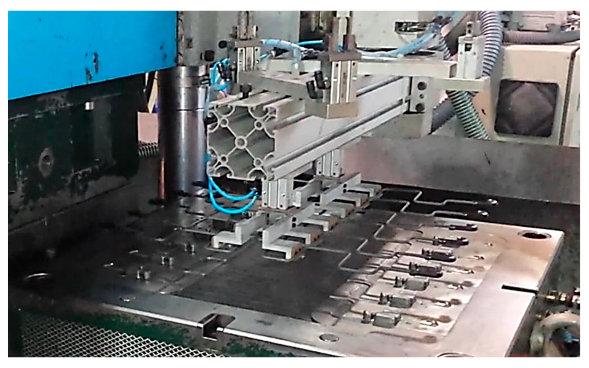
The implementation of the system was performed as planned, as can be seen in
Figure 13. The complete product is not shown due to confidentiality reasons.
The implementation of the system allowed the measurement of cycle time. It was possible to observe that each cycle could be reduced by 20 s, improving the global cycle time. This cycle time contrasts with the 25 s spent by the same operation performed manually, thus saving 5 s (−20%). In order to ensure that the data were viable, these values were calculated based on 500 observations, exhibiting a standard deviation of less than 1 s. Additionally, no problems were detected regarding the material transportation from machine to machine, thus ensuring the reproducibility of the obtained data. The time saved is compatible with the over-injection cycle, regarding the solidification of the polymer material.
After analyzing the functioning of the system, carried out previously, it is necessary to analyze the economic aspect. By the analysis of
Table 2, it is possible to compare the manual process with the optimized process.
Improving the process provided a reduction of 5 s in the cycle time of the injection process. With this improvement, the company increased the productivity by almost 20%, and reduced the use of three co-workers (one co-worker per shift). The implementation of this set of devices was only possible with the reuse of some available components in the company that had no utility until the start of this project, plus some new components—a total investment of EUR 16.200. The reused components were valued at half their original value, considering new components with similar characteristics. Considering the savings in terms of cycle time and work labor (almost EUR 14.400 per year for each co-worker), the payback time is less than 5 months.
5. Discussion
This work intended to prove that complex problems can be solved with the help of automation, with low costs and without the need for robotics, presenting a short period of return on investment while not implying drastic changes in the company’s layout. Indeed, similar developments have been made by other authors, namely, Costa et al. [
2], who designed a novel machine based on conventional automation, eliminating persistent quality problems, or Nunes et al. [
7] who designed a novel assembly system based on conventional automation and able to eliminate human labor assembly operations, increasing productivity as well. Moreover, Costa et al. [
9] developed novel equipment to assemble complex automotive parts based only on conventional automation and artificial vision for quality control and achieving significant improvements in production rate and repeatability, or even the upgrade carried out by Santos et al. [
21] who improved equipment for the production of components for tire manufacturing based solely on conventional automation, significantly reducing the downtime of this type of equipment and increasing the OEE (overall equipment efficiency). These works, as well as others presented in the Introduction and Background of this article [
6,
22,
23,
43], refer to the outline of production systems that ensure increased production efficiency, as well as drastically superior reliability, requiring relatively low investment. In fact, the investment required for this project is quite low, thanks to the reuse of some discarded material from previous projects, which results in a very low period of investment return, making it extremely appealing. Silva et al. [
41] point to a payback period of 21.5 months for upgrading equipment also dedicated to the automotive industry. However, when it comes to redesigning equipment with more proof-of-concept changes, the payback periods become much longer, even considering deep reductions in cycle times and elimination of jobs, as mentioned by Costa et al. [
2], in which the amortization period indicated is 24 months. In turn, Magalhães et al. [
40] point to a short period (8.2 months) for the return on investment related to wire separation equipment, directly linked to the present work.
As the main outcomes and transferable knowledge, the following achievements should be considered:
- (a)
A new system of storage and organized dispensing of wires has been created that works as an insert in a final product consisting of shaped metallic wires over-injected with polymeric material. The system of storage, separation, and organization of the wires to supply the gripper is completely new and innovative. It can be used for the manufacturing of many other products, especially applications where bent wires are used.
- (b)
The use of the same gripper for feeding wires, adjusting/tamping them in the mold, and subsequently extracting the over-injected part, is equally innovative and can be replicated in many other situations found in the production of several components.
- (c)
Adoption of extremely compact and low-cost solutions can also be an encouraging factor for the application of similar systems in other projects in the automotive industry, or even in household products.
- (d)
There are, however, some limitations to the developed system, particularly the wire-feeding operations that are placed onto the machine. These operations are still performed manually, thus, the material flow is not yet fully automated, leading to the need to automate the previous workstation.
- (e)
Visual control is still performed by workers, as such, artificial visual inspection could be implemented, in order to automate the control of the finished product.


 ,
, 


