Experimental Investigation of a Large Tilting-Pad Journal Bearing—Comparison of a Flooded and Non-Flooded Design


Product Development, Ruhr-University Bochum, 44801 Bochum, Germany
*
Author to whom correspondence should be addressed.
Lubricants 2022, 10(5), 83; https://0-doi-org.brum.beds.ac.uk/10.3390/lubricants10050083
Submission received: 28 February 2022
/
Revised: 26 April 2022
/
Accepted: 28 April 2022
/
Published: 3 May 2022
(This article belongs to the Special Issue Advances in Lubricated Bearings)
Abstract
:In tilting-pad journal bearings (TPJB), power loss corresponds to the internal friction in the shearing of the oil. Besides the lubrication gap, intermediate spaces between the pads account for a notable amount of frictional losses. Against the background of increasing demands for efficiency and sustainable use of resources, the reduction of power loss takes a key position in the further development of bearings. In our research, we compare two bearing lubrication concepts of a five-pad TPJB. Our objective is to work out the influence of different lubrication methods and bearing housing designs on the bearing operation characteristics. We conduct experimental testing of a 500 mm TPJB in two different bearing configurations with respect to the lubrication concept: an oil-flooded and non-flooded bearing design. In the flooded bearing design, oil is supplied via spray-bars and axial seals ensure the inter-pad spaces to be completely filled with oil. The non-flooded design comes without axial seals but oil drain channels to avoid oil accumulation in the bearing. In the latter design, oil is fed in via leading edge grooves (LEG). For the non-flooded bearing design, the experimental data show that the unloaded pads are not completely filled with oil and therefore, no pressure build-up occurs. The absence of additional load on the lower pads compared to the flooded design results in an increase of minimum film thickness. With the non-flooded design, power loss at high speeds is reduced to almost half. As a result, the efficiency of the entire turbomachinery application can be considerably improved.
1. Introduction
Hydrodynamic bearings are used in a wide range of applications in rotating machinery. The wear-free operation under full lubrication and the easy mounting are the main advantages. In turbomachinery, tilting pad journal bearings (TPJB) play an important role as they show good stiffness and damping characteristics and do not tend to cause self-excited vibrations. With an increasing demand for better efficiency of high-speed machinery, the aim is to keep the power loss of the bearings as low as possible.
In hydrodynamic bearings, the power loss is equivalent to the heat resulting from friction. The heat is dissipated as an unavoidable consequence of the shearing of the oil, which is vital for the pressure build-up in the lubrication gap between shaft and bearing. Besides the lubrication gap, notable friction power occurs in other areas of the bearing that do not contribute to pressure build-up. In TPJB, the friction in the intermediates space between two pads account for a significant proportion of the power loss. Depending on the mixture of oil and air, the amount of friction power in these pad intermediate spaces can be up to 50% of the total bearing power loss [1]. For a fixed-pad bearing, Hagemann and Schwarze [2] find that up to 35% of the power loss relates to dissipation in the interpad spaces.
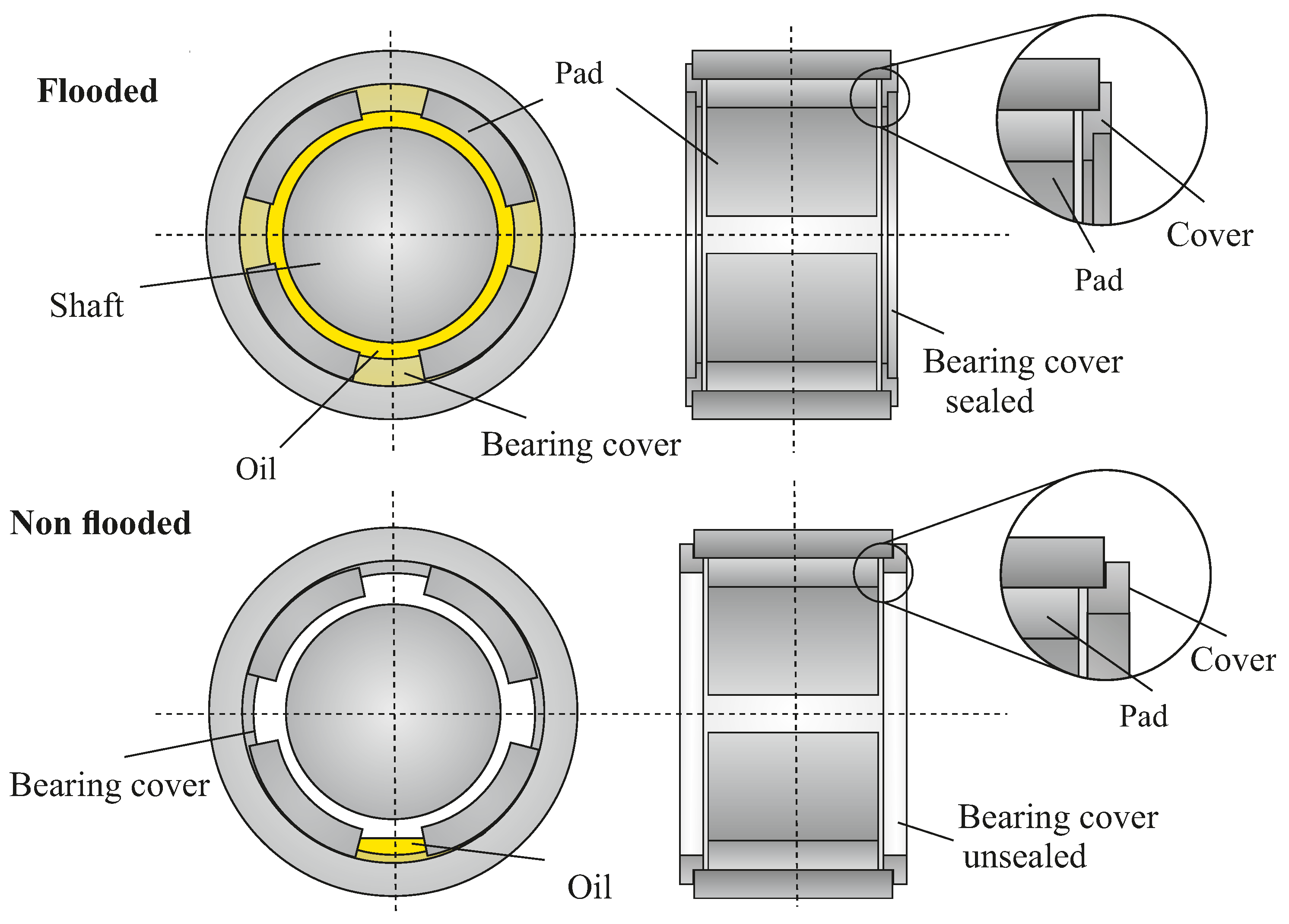
Regarding the lubrication concept of TPJB, an oil-flooded and non-flooded design can be assumed as two limiting cases. While in a flooded bearing design the intermediate spaces between the pads are fully filled with oil, in a non-flooded design these spaces are theoretically oil-free. In both cases the intermediate spaces do not contribute to the hydrodynamic load carrying capacity of the bearing, but have an effect on the converted frictional power.
Regardless of the bearing design, a relatively simple approach to reduce friction power loss is to adjust oil supply. Simmons and Dixon [3] investigate experimentally a considerable reduction of lubricant supply for a 200 five-pad TPJB in conventional design without compromising the reliability of the bearing. By reducing the lubricant flow rate to half, they lower power loss by 20% at a circumferential speed of 105 /. Studies of San Andres et al. [4,5] show similar results for two 102 TPJB with flooded seal ends. For a five-pad TPJB [4], a 15% decrease in power loss at shaft speed 74 / is realized by a flow reduction of 50%. With the same flow reduction for a four-pad TPJB [5], power loss is reduced by 19% at 64 /.
However, the oil supply cannot be reduced at arbitrary rates, since starvation in the lubrication gap and rising temperatures are limiting factors [6]. Therefore, alternative lubrication methods have been developed to supply oil directed towards the leading edge region of the pad or directly into the lubrication gap [7,8]. Harangozo et al. [9] compare the effects of a directed lubrication, where oil is fed in via spray-bars with several inlet holes, a direct lubrication via leading-edge-grooves (LEG) and a conventional flooded lubrication on the performance of a 127 four-pad TPJB. With the directed and direct lubrication, the bearing is designed without axial seals, so that bearing is not flooded with oil. In the experimental results, the flooded bearing shows the greatest power loss, while for the directed lubricated bearing the lowest power loss is observed. The authors attribute the differences in the spray-bar and LEG lubricated bearing to the generally lower temperatures and thus, the higher viscosity with the LEG lubricated bearing as well as to the higher shear stress losses within the LEG. Experimental analyses of a 120 four-pad TPJB in a spray-bar and direct LEG lubricated configuration at a broad range of rotational speed show similar results [10]. A comparison of both lubrication methods shows a considerably lower frictional power for spray-bar lubrication than for the LEG lubrication at higher speeds. Hagemann and Schwarze relate these findings to the fact, that with the LEG nearly the entire oil is supplied to the lubrication gap, while with the spray-bars a bypass flow emerges.
A proven method for an evacuation of the intermediate spaces between the pads to reduce maximum bearing temperatures is a TPJB design with open end seals and large drain channels [7,11]. Nicholas [12] investigates a 102 five-pad TPJB in a flooded pressurized housing design in comparison with an evacuated housing design featuring directed lubrication on the temperatures without considering power loss. Dmochowski and Blair [13] examine a 99 five-pad TPJB in an evacuated housing design, realized by enlarging the clearance of the end seals. Compared to a flooded bearing, oil evacuation leads to a reduction in power loss of 25% at highest shaft speeds /. With an additional reduction in oil flow by approximately 30%, a decrease in power loss of 12% is observed. Bang et al. [14] evaluate a 301 six-pad TPJB with conventional and LEG lubrication method, each with and without end seals. Detecting a reduction of power loss in the bearings without end seals, they find the lowest power loss for the conventional lubricated bearing without seals (39.2% lower than for the conventional bearing with seals). As in other works, a decrease in power loss is achieved by reducing oil flow rate. Sano et al. [15] obtain comparable results for a large-scale TPJB with nominal diameter 890 . By leaving out the upper two pads of a four-pad TPJB in a non-flooded design with spray-bar lubrication, power loss is decreased to less than half.
In this paper, we experimentally investigate a five-pad TPJB with nominal diameter 500 in a flooded and non-flooded design. In the flooded design, the bearing is axially sealed and assumed to be fully filled with oil. By leaving out the axial seals in the non-flooded design, intermediate spaces between pads are only partially filled with oil. The aim of our research is to analyse how the bearing design and lubrication method influence the load carrying capacity and efficiency of the bearing. The experimental testing takes place at the Bochum test rig for large journal bearings. We measure the main operating parameters oil film thickness, oil film pressure and pad temperatures as well as the friction power. We compare the measurement data of both bearing designs and identify the impact of the lubrication method on the bearing characteristics. The approach presented in this paper allows for a direct comparison of different lubrication concepts for a large-scale TPJB. In industrial applications, bearings are frequently operated at reduced oil supply rates without modifying the bearing design. Therefore, oil accumulation may occur despite the non-full flooding. The test bearing in the non-flooded design in our research is designed in such a way that no oil accumulates in the pad intermediate spaces and non-flooding can be explicitly investigated.
2. Experimental Set-Up
2.1. Test Rig
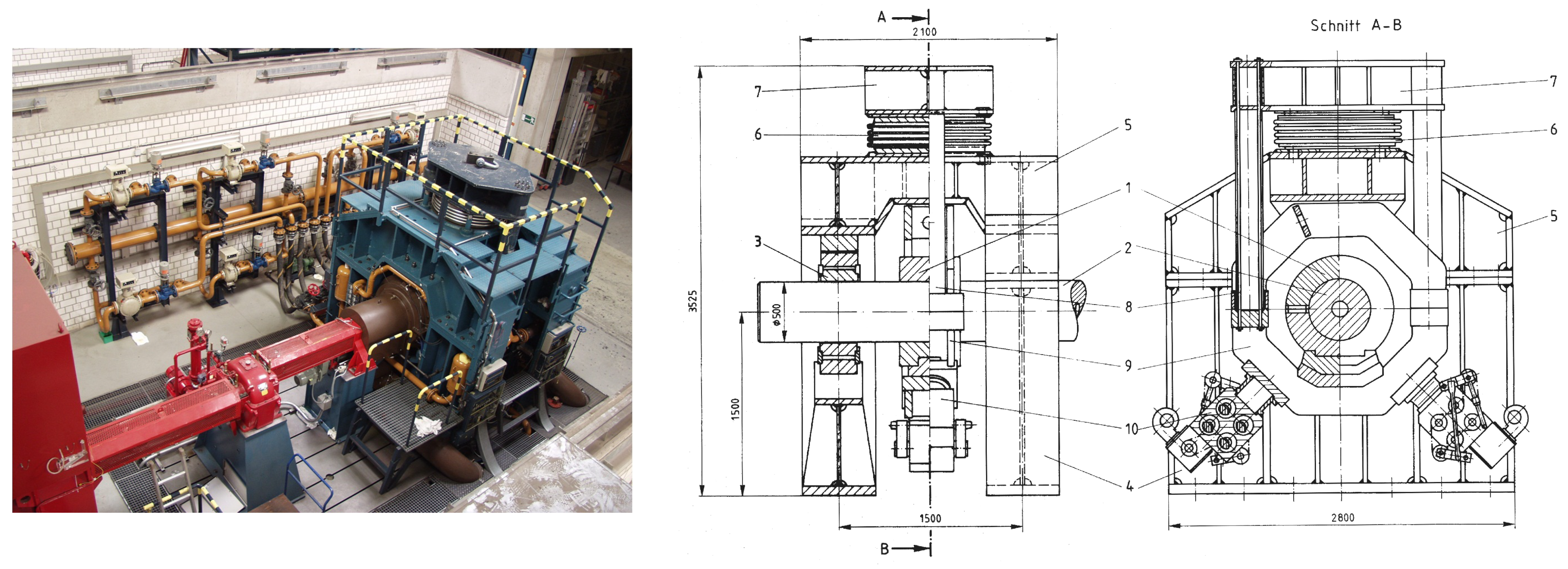
We carry out the experimental testing on the Bochum test rig for large journal bearings. The test rig was built in the 1980s to examine original-sized turbine bearings with a nominal diameter of 500 . The maximum length of the test bearing is 500 . The shaft is powered by a DC drive (Brown, Boveri & Cie (BBC, Baden, Switzerland)) and can be accelerated up to a rotational speed of 4000 rpm depending on the friction loss what corresponds to a maximum circumferential velocity of /. The lubricant used is a turbine oil ISO VG 32 (Esso Teresso 32). Figure 1 shows a top view (left) and a technical drawing (right) of the test rig.
In the test rig, the shaft (2) is supported by two symmetrically aligned support bearings (3), which are designed as three-pad TPJB. The test bearing (1) is arranged centrally between the support bearings in a rigid frame (9). The rigid frame is connected to the upper part of the test rig frame (5) via two draw bars (8), a traverse (8) and a pneumatic bellow (6). The upper part and the two support bearings are supported by the lower part of the test rig (4). By pressurizing the bellow, the test bearing is pulled against the shaft from below with a maximum bearing force of 1 .
The shaft is designed as a hollow shaft and equipped with a film thickness and pressure measuring system. Two capacitive distance sensors and two pressure probes are mounted in the mid-plane of the shaft at 90° to each other with same sensor types being 180° apart. A shifting device at the drive end of the shaft allows to shift the rotating shaft in axial direction and thus the sensor plane across the whole test bearing width during measurement. With this equipment, both fluid film thickness and pressure distribution can be captured in a high-resolution two-dimensional (2D) data field. In circumferential direction 240 data points are measured, while in axial direction up to 4000 data points can be recorded, depending on the rotational speed. Due to the capacitive measurement principle, the fluid film thickness can only be determined reliably in areas where the space between shaft and bearing is completely filled with oil. By contrast, areas of cavitation and oil-air-mixture can be detected by this characteristic.
Beyond the stationary force, the test bearing can be loaded by sinusoidal dynamic forces. Two vibration generators (10) are mounted to the rigid frame (9) at 90° to each other and at 45° to the vertical load direction. The additional dynamic forces created by the vibration generators are detected with the pressure probes. Relative shaft movement is measured by four eddy current distance probes to determine the dynamic spring and damping coefficients of the test bearing. A detailed description of the vibration generators, the measurement system and post-processing is presented in Kukla et al. [16].
2.2. Test Bearing Designs
The test bearing in our investigations is a five-pad TPJB with nominal diameter 500 . The bearing is loaded in a load-between-pad configuration with double-tilt supported pads. The tilting in both axial and circumferential direction for a better compensation of misalignment between shaft and bearing is enabled by an elliptical pivot geometry. This pivot geometry results from a manufactured radius in axial direction of both, the pads back and bearing ring. The two lower, highly loaded pads are each equipped with a hydrostatic jacking groove above the pivot area. Both pads are manufactured with an axial concave profile on the running surface, following Kukla et al. [17] to compensate for thermal crowning at high specific loads. The bearing key parameters are summarized in Table 1.
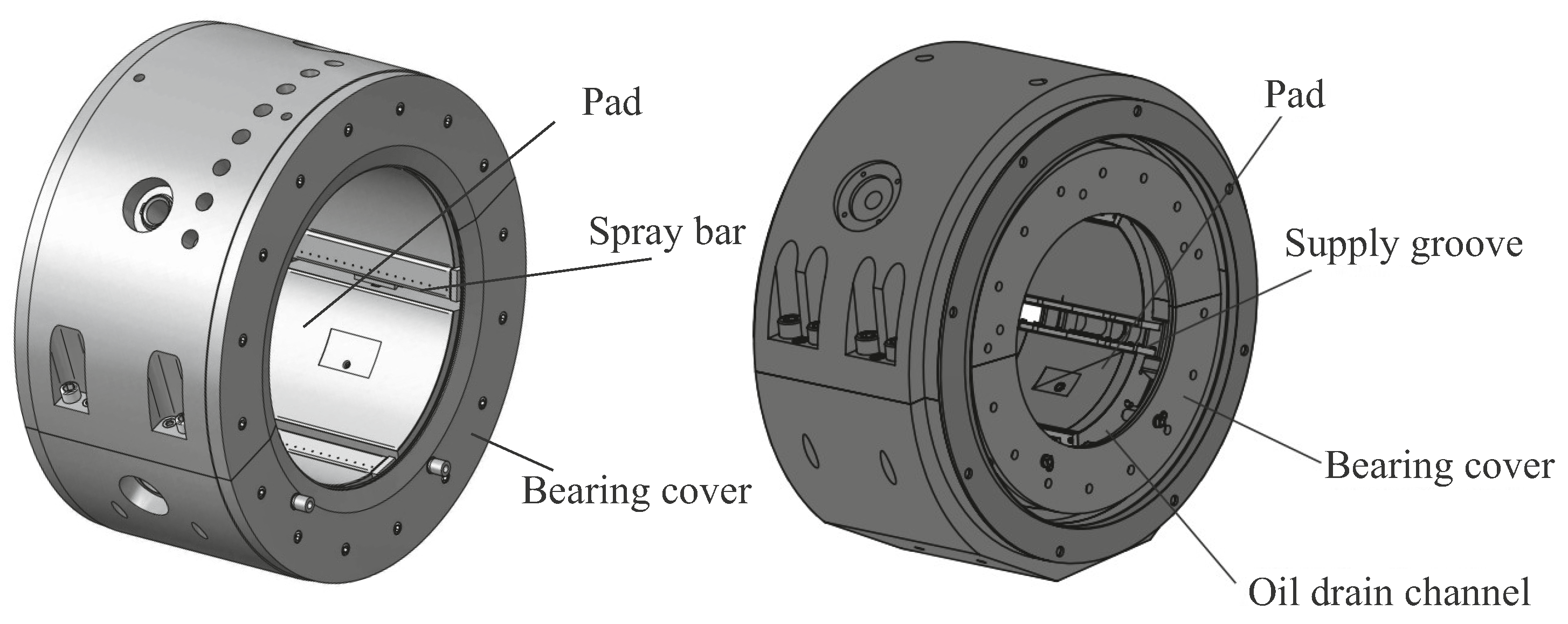
We investigate the test bearing in a flooded and non-flooded design. In the flooded design, oil is supplied via spray-bars with each 19 holes in the intermediate space between two pads (Figure 2). In circumferential direction, the pads are kept in place by the spray-bars. Axial sealings on both sides ensure that the bearing is permanently filled with oil and therefore in a flooded condition (Figure 3).
In contrast, no axial sealings are inserted in the non-flooded design and the intermediate space between the pads is enlarged in radial direction. Additionally, oil drain channels and large spacing between pads and axial bearing covers are added to avoid oil accumulation in the bearing except for the lubrication gap (Figure 3). For a sufficient feeding of the lubrication gap with oil, the spray-bars are replaced with a ‘leading edge groove’ (LEG) in the non-flooded design directly attached at the pads leading edge (Figure 2). This directed lubrication allows to supply oil only in the dedicated areas. The two lower pad are each equipped with additional ‘trailing edge grooves’ (TEG) for active cooling of the pads trailing edge, since the heat transfer in this region is much lower compared to the flooded bearing design ([18]). A safety mechanism mounted in the pivot area to keep the pads in place hinders the oil feed through the pivot. Hence, oil is fed in via the pads axial edges. In both bearing designs, flooded and non-flooded, the spray-bars respectively the LEG and TEG are supplied separately via several internal galleries and a ring channel between bearing ring and housing. For the investigations in this paper, no oil is supplied in the TEG.
2.3. Calorimetric Determination of Frictional Power
In hydrodynamic bearings, the frictional power is the power converted into heat in the gap between oil-wetted surfaces. The friction power is defined as:
For the test bearing, we assume that the frictional power is mainly dissipated via the lubricating oil. During testing, the oil volume flow rate , the oil inlet temperature and outlet temperature are measured. The out-flowing oil is first led into a mixing tank before it is returned to the oil tank. At the outlet of the mixing tank, the temperature is captured at ten measuring points, which are recorded by a data logger. By sorting out the minima and maxima and subsequent averaging, reliable results can be obtained with regard to the oil outlet temperature. Based on these measurement data, the converted frictional power at constant density and constant specific heat capacity can be determined calorimetrically using the following expression:
Considering the mass flow , which remains constant due to mass conservation, instead of the volume flow and the temperature dependence of specific heat capacity , leads to the following expression:
According to [19], the temperature-dependent density for lubricating oil can be calculated using the density at 15 °C as follows:
with and . For the relevant temperature range, there is a linear relationship between the specific heat capacity and the temperature T, resulting in the following expression for the above integral:
using the mean oil temperature . Taking the correlations shown into account, the equation for the calorimetric determination of the frictional power is:
3. Experimental Results
In the following section, the operating characteristics of the non-flooded bearing design are compared with those of the flooded one [20]. For both bearing designs, flooded and non-flooded, the nominal oil flow rate is /.
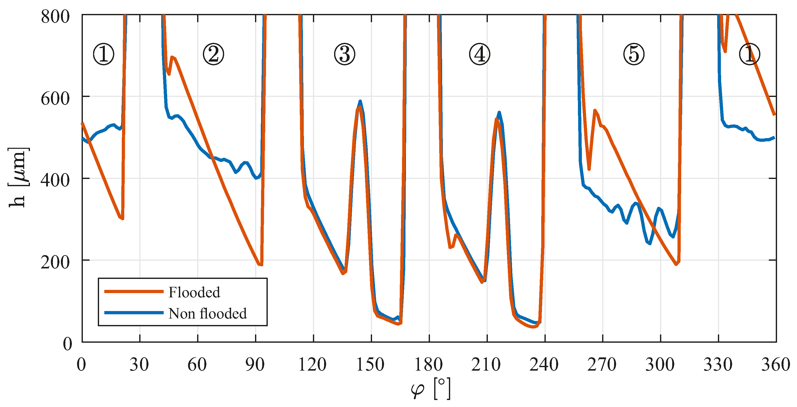
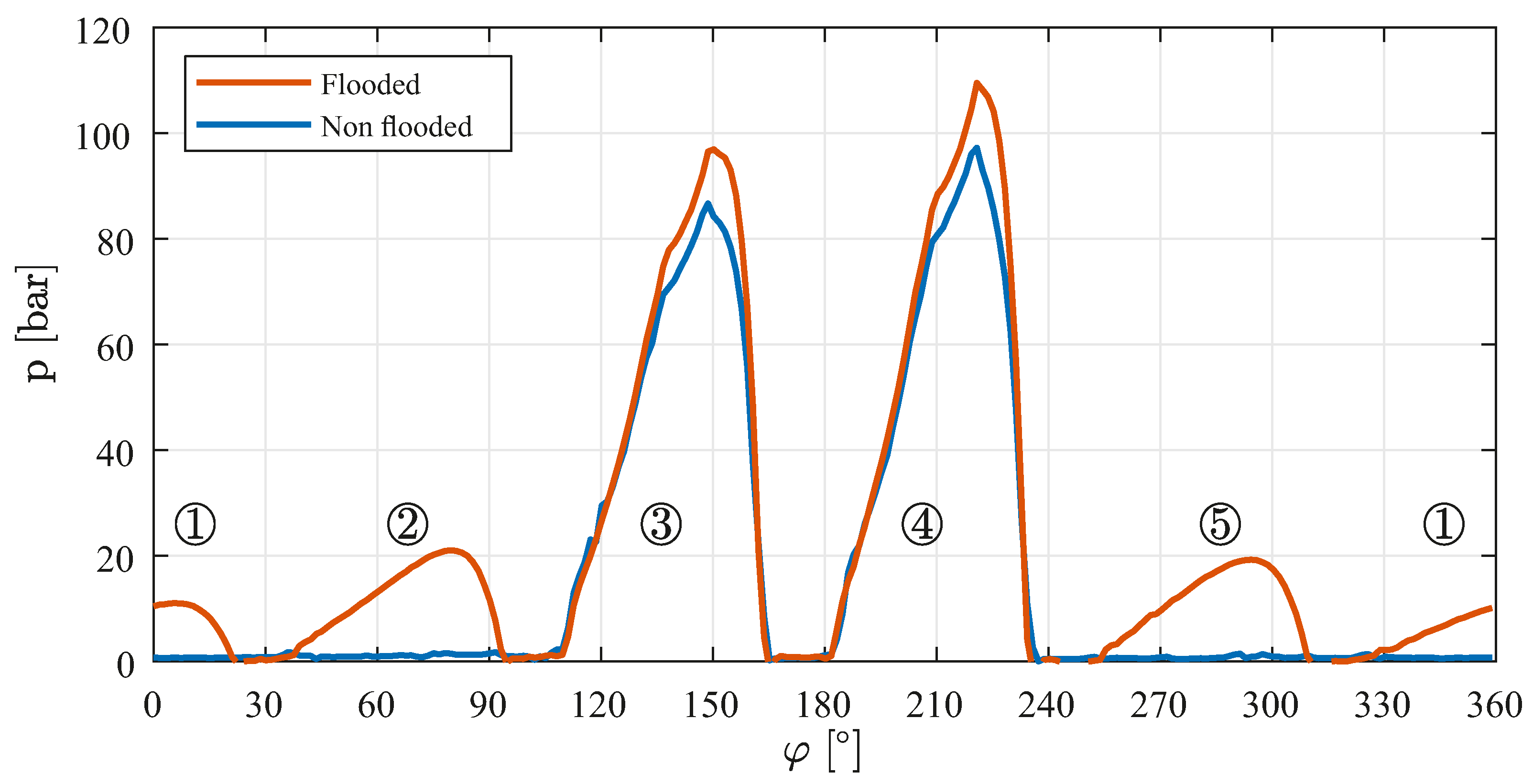
As an example, Figure 4 shows the lubricant film thickness and Figure 5 the lubricant film pressure of both bearing designs plotted against the bearing circumference in the bearing center. The peaks in lubricant film thickness for pads 3 and 4 (≈135°–150° and 207°–222°) and the corresponding disruption in pressure are due to the hydrostatic jacking grooves. In the flooded version, all five pads show complete gap filling, while in the non-flooded version only the lower loaded pads 3 and 4 are fully filled. Here, a significant difference between the two designs becomes apparent. Due to the sealed bearing configuration on the sides, in the flooded design the complete bearing is almost completely filled with oil. Each pad is provided with a sufficient amount of lubricant and a hydrodynamic pressure build-up is generated. By redesigning the spaces between the pads (elimination of the spray-bars) and increasing the axial distance between the pads and the bearing cover in the non-flooded design, pressure build-up of the lubricant is not possible. Only the oil provided at the leading edge is supplied to each pad. To completely fill the gaps of the non-loaded pads, the total volume flow supplied would have to be significantly increased.
The differences described can also be found in the measured pressure distribution. While in the non-flooded bearing design only the loaded pads generate a hydrodynamic pressure build-up, in the flooded design a pressure build-up is observed for all five pads, as shown in Figure 5. As a result, the lower pads 3 and 4 are subject to additional loads from upper pads 1, 2 and 5 in addition to the external load, resulting in higher maximum pressure and smaller film thickness.
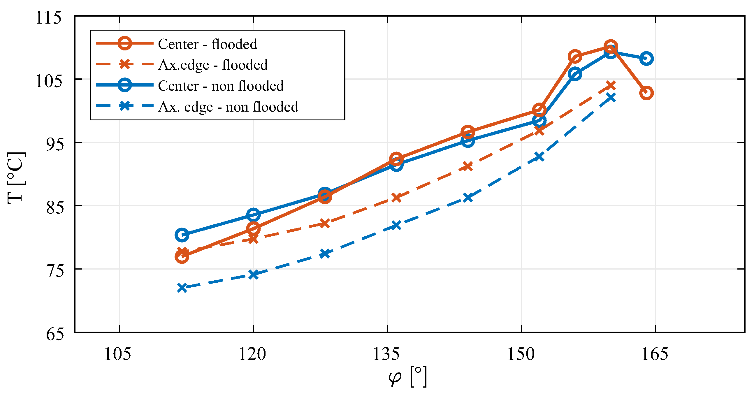
The temperature curves of a pad of the respective bearing designs are in qualitative agreement, see Figure 6. A comparison of the measured temperatures at the leading edge of the pad shows differences in the gap entry temperatures between the flooded and non-flooded versions of the bearing. For the flooded design, no particular difference across the bearing width can be detected at the pad beginning. A clear difference in the initial temperatures can be seen across the pad width for the non-flooded bearing configuration (ax. edge–center). The temperatures measured laterally are approx. 10 K below the temperature in the center of the pad. The reason for the temperature differences at the beginning of the pad is the different lubricant supply systems of the two bearing designs. In the flooded version, the fresh oil is supplied via spray-bars in the inter-pad spaces, resulting in a more homogeneous mixing temperature across the bearing width. In the non-flooded design, the lubricant is supplied via a groove at the leading edge of the pad. Due to the groove design, the temperature of the fresh oil supplied dominates in the peripheral areas. In the center of the bearing, the lubricant is mixed with the hot oil carried over from the previous pad, so that the temperatures in this area are higher than those in the peripheral areas and the axial temperature gradient is ultimately established at leading edge.
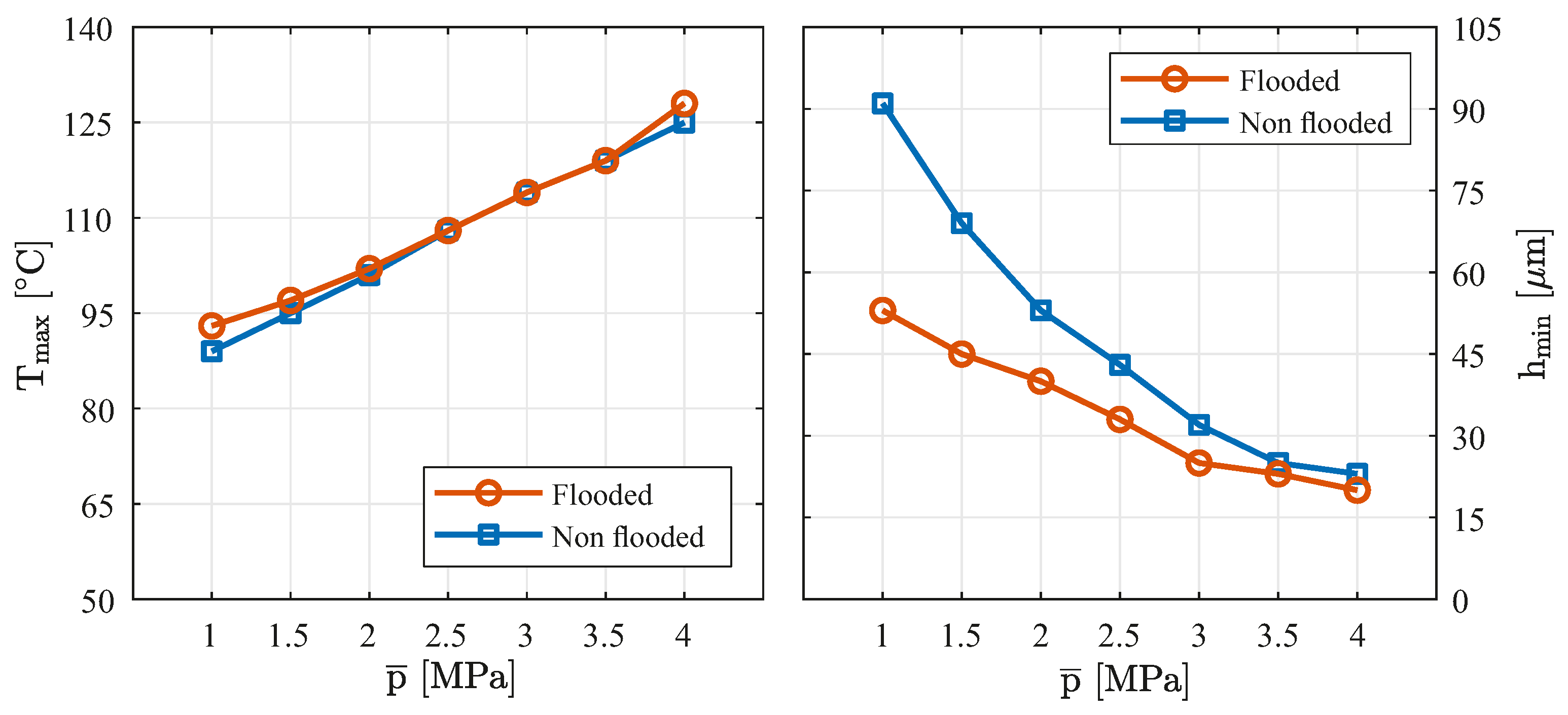
Figure 7 shows the experimentally determined maximum bearing temperatures (left) and the minimum lubricant film thicknesses (right) of the different bearing designs above the specific bearing load at speed of 3000 rpm. It can be seen that the curves of the maximum bearing temperatures of the flooded and non-flooded variants are consistent between MPa and MPa. Only in the lower bearing load range and at MPa, the non-flooded bearing operates at a lower maximum temperature. The direct comparison of the measured minimum film thickness shows that the bearing in the flooded design has a significantly lower film thickness over the complete load range than in the non-flooded design.
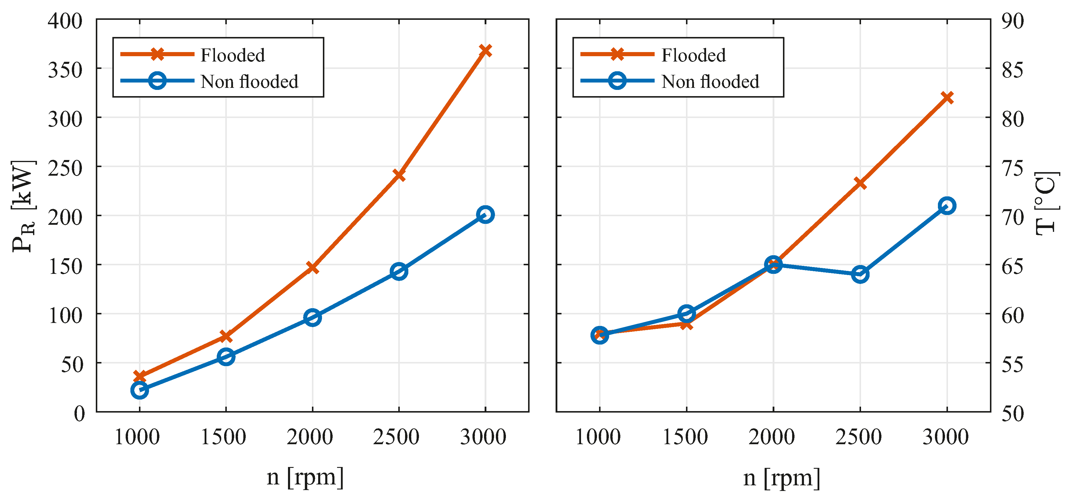
A comparison of the experimentally determined power losses of the flooded and non-flooded bearing configurations shows that the non-flooded design allows for a significant reduction of the power loss. For this purpose, the left part of the Figure 8 plots the measured power losses of both variants at a specific bearing load of MPa as a function of speed. The corresponding measured shaft temperatures are plotted in the right part of the Figure.
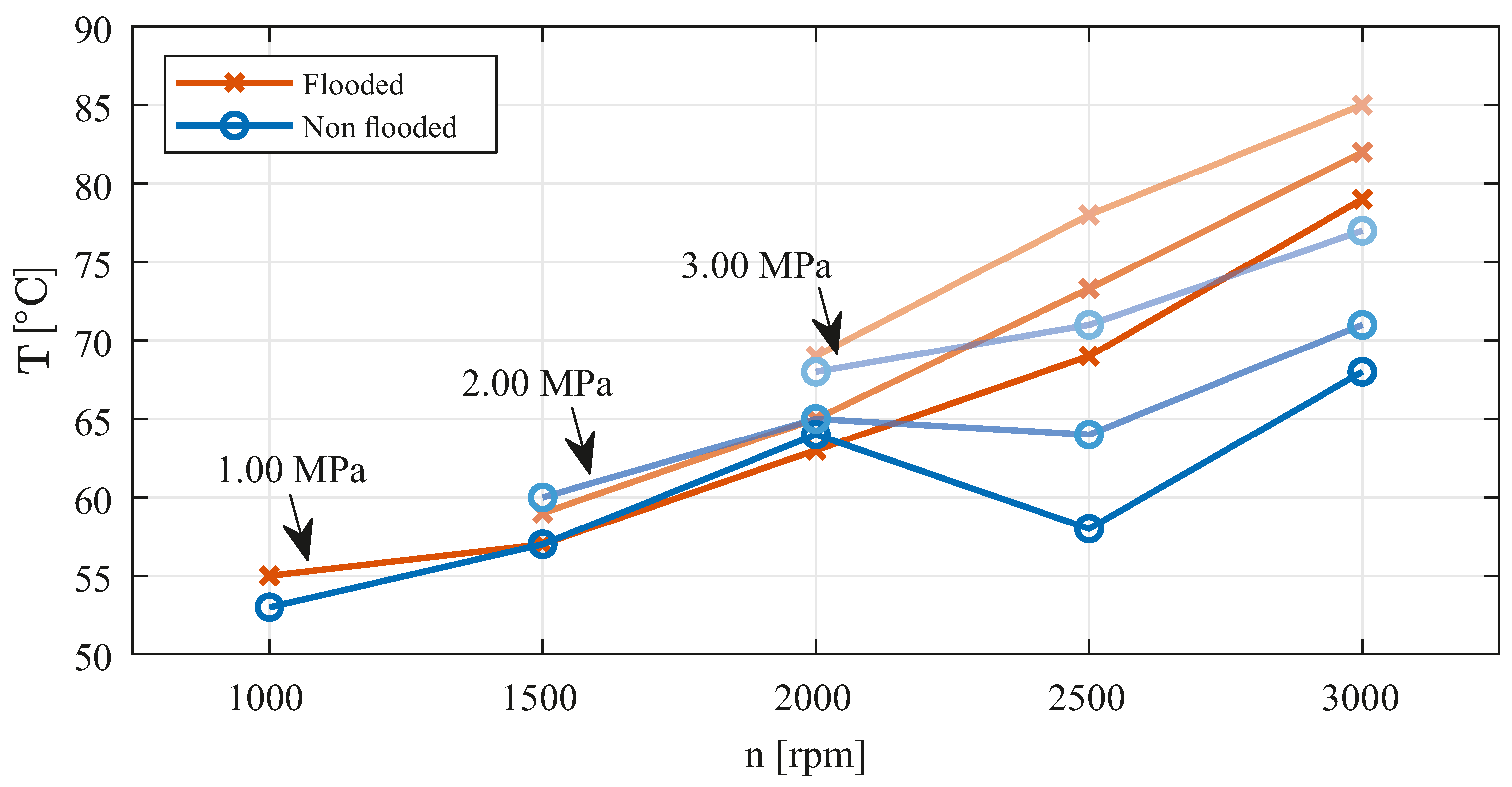
On the one hand, the reduction in frictional power is due to the non-flooded gaps and, on the other hand, to the incipient deficient lubrication of the unloaded pads. The oil-free gaps and the oil-air mixture in the incompletely filled gaps result in a lower shear stress between the surfaces compared with a fully filled bearing. When looking at the associated measured shaft temperatures (Figure 8 on the right), the occurring deficient lubrication of the unloaded pads in the non-flooded bearing design becomes apparent. While in the flooded lubrication the shaft temperature rises steadily above speed, indicating complete gap filling of all pads above speed, the course of the non-flooded design shows a slight drop in shaft temperature between speeds 2000 rpm and 2500 rpm. This temperature drop is due to the onset of insufficient lubrication of the unloaded pads. In these areas, the shaft is cooled or, in direct comparison with flooded lubrication, the heat input is reduced by the energy dissipated in the lubrication gap. This effect can be observed particularly at comparatively low loads, while at high loads partial filling of the unloaded pads can be observed over the entire speed spectrum (no drop in the measured shaft temperature over the speed). For this purpose, Figure 9 shows the measured shaft temperatures of both bearing variants versus speed for different bearing loads.
4. Discussion and Conclusions
In our investigations, we have experimentally examined a bearing design in two different configurations. The two bearings differ only in the oil feed and the axial sealing. All other parameters are identical.
By comparing the experimentally determined operating characteristics of the flooded and non-flooded design, it can be shown that the non-flooded design has a positive influence on the load carrying capacity (higher minimum lubricant film thickness at the same load level). Mainly this can be related to the non-existing hydrodynamic pressure build-up of the unloaded pads. Due to the pressure build-up in the upper pads in the flooded version, there is an additional load on the lower loaded pads. The measured pad temperatures are at an identical level, but differ at the pad edges due to the different oil regimes in the intermediate spaces.
However, the major difference between the two configurations is evident in the measured frictional powers. The power loss at a speed of 3000 rpm can be reduced by almost half by designing the bearing in a non-flooded configuration. This reduction in power loss is attributed to the unloaded pads and the spaces between them not being filled with oil. In these areas, there is less shear stress on the shaft surface and the frictional power converted in the bearing is reduced.
In conclusion, we demonstrate that the concept of lubrication can positively influence the frictional performance of a TPJB without reducing or increasing the operational safety parameters such as minimum lubricant film thickness or maximum bearing temperature.
Author Contributions
Conceptualization, M.S. and N.B.; methodology, M.S. and N.B.; experimental investigation, M.S. and N.B.; writing—original draft preparation, M.S. and N.B.; writing—review and editing, M.S., N.B. and B.B.; supervision, B.B.; project administration, N.B.; funding acquisition, N.B. All authors have read and agreed to the published version of the manuscript.
Funding
This Project is supported by the Federal Ministry for Economic Affairs and Climate Action (BMWK) on the basis of a decision by the German Bundestag. The financial support was assigned by the Industrial Research Association (AiF e. V.) in the project “Verbesserte Effizienz großer, schnelllaufender Radialkippsegmentgleitlager für verlustleistungskritische Anwendungen”.
Data Availability Statement
The data presented in this study are available on request from the corresponding author.
Acknowledgments
We acknowledge support by the Open Access Publication Funds of the Ruhr-Universität Bochum. The authors would like to thank D. Schüler for his valuable advice and GTW Alpen, especially C. Weißbacher, for the support of the experimental investigation and project administration.
Conflicts of Interest
The authors declare no conflict of interest.
Abbreviations
| B | Bearing length |
| Specific heat capacity | |
| Radial clearance | |
| D | Nominal diameter |
| h | Film thickness |
| Pad preload | |
| Mass flow | |
| M | Torque |
| n | Rotor speed |
| p | Film pressure |
| Specific bearing load | |
| Frictional power | |
| Power loss | |
| r | Radius |
| t | Thickness |
| T | Temperature |
| Temperature difference | |
| Volume flow | |
| Density | |
| Angular coordinate | |
| Relative bearing clearance | |
| Rotational speed | |
| LEG | Leading edge groove |
| TEG | Trailing edge groove |
| TPJB | Tilting-pad journal bearing |
References
- Buchhorn, N. Einfluss einer Niederdrucktasche auf die Wärmeabfuhr an der Segmenthinterkante eines großen Radialkippsegmentlagers. Ph.D. Thesis, Ruhr-Universität Bochum, Bochum, Germany, 2020. [Google Scholar]
- Hagemann, T.; Schwarze, H. A Model for Oil Flow and Fluid Temperature Inlet Mixing in Hydrodynamic Journal Bearings. J. Tribol. 2019, 141, 021701. [Google Scholar] [CrossRef]
- Simmons, J.E.L.; Dixon, S.J. Effect of Load Direction, Preload, Clearance Ratio, and Oil Flow on the Perfonmance of a 200 mm Journal Pad Bearing. Tribol. Trans. 1994, 37, 227–236. [Google Scholar] [CrossRef]
- San Andrés, L.; Jani, H.; Kaizar, H.; Thorat, M. On the Effect of Supplied Flow Rate to the Performance of a Tilting-Pad Journal Bearing—Static Load and Dynamic Force Measurements. J. Eng. Gas Turbines Power 2020, 142, 121006. [Google Scholar] [CrossRef]
- San Andrés, L.; Toner, J.; Alcantar, A. Measurements to Quantify the Effect of a Reduced Flow Rate on the Performance of a Tilting Pad Journal Bearing with Flooded Ends. J. Eng. Gas Turbines Power 2021, 143, 111012. [Google Scholar] [CrossRef]
- Nicholas, J.C.; Elliott, G.; Shoup, T.P.; Martin, E. Tilting Pad Journal Bearing Starvation Effects. In Proceedings of the 37th Turbomachinery Symposium, Houston, TX, USA, 8–11 September 2008; pp. 1–10. [Google Scholar] [CrossRef]
- Nicholas, J.C. Tilting Pad Bearing Design. In Proceedings of the 23rd Turbomachinery Symposium, Dallas, TX, USA, 13–15 September 1994; pp. 179–194. [Google Scholar] [CrossRef]
- Dmochowski, W.; Brockwell, K.; DeCamillo, S.; Mikula, A. A Study of the Thermal Characteristics of the Leading Edge Groove and Conventional Tilting Pad Journal Bearings. J. Tribol. 1993, 115, 219–226. [Google Scholar] [CrossRef]
- Harangozo, A.V.; Stolarski, T.A.; Gozdawa, R.J. The Effect of Different Lubrication Methods on the Performance of a Tilting-Pad Journal Bearing. Tribol. Trans. 1991, 34, 529–536. [Google Scholar] [CrossRef]
- Hagemann, T.; Schwarze, H. Theoretical and Experimental Analyses of Directly Lubricated Tilting-Pad Journal Bearings with Leading Edge Groove. J. Eng. Gas Turbines Power 2019, 141, 051010. [Google Scholar] [CrossRef]
- Tanaka, M. Thermohydrodynamic Performance of a Tilting Pad Journal Bearing With Spot Lubrication. J. Tribol. 1991, 113, 615–619. [Google Scholar] [CrossRef]
- Nicholas, J. Tilting Pad Journal Bearings with Spray-Bar Blockers And By-Pass Cooling For High Speed, High Load Applications. In Proceedings of the 32nd Turbomachinery Symposium, Houston, TX, USA, 8–11 September 2003; pp. 27–38. [Google Scholar] [CrossRef]
- Dmochowski, W.M.; Blair, B. Effect of Oil Evacuation on the Static and Dynamic Properties of Tilting Pad Journal Bearings. Tribol. Trans. 2006, 49, 536–544. [Google Scholar] [CrossRef]
- Bang, K.B.; Kim, J.H.; Cho, Y.J. Comparison of power loss and pad temperature for leading edge groove tilting pad journal bearings and conventional tilting pad journal bearings. Tribol. Int. 2010, 43, 1287–1293. [Google Scholar] [CrossRef]
- Sano, T.; Magoshi, R.; Shinohara, T.; Yoshimine, C.; Nishioka, T.; Tochitani, N.; Sumi, Y. Confirmation of performance and reliability of direct lubricated tilting two pads bearing. Proc. Inst. Mech. Eng. Part J. Eng. Tribol. 2015, 229, 1011–1021. [Google Scholar] [CrossRef]
- Kukla, S.; Hagemann, T.; Schwarze, H. Measurement and Prediction of the Dynamic Characteristics of a Large Turbine Tilting-Pad Bearing Under High Circumferential Speeds. In Proceedings of the ASME Turbo Expo: Turbine Technical Conference and Exposition, San Antonio, TX, USA, 3–7 June 2013. [Google Scholar] [CrossRef]
- Kukla, S.; Buchhorn, N.; Bender, B. Design of an axially concave pad profile for a large turbine tilting-pad bearing. Proc. Inst. Mech. Eng. Part J. Eng. Tribol. 2017, 231, 479–488. [Google Scholar] [CrossRef]
- Buchhorn, N.; Stottrop, M.; Bender, B. Influence of Active Cooling at the Trailing Edge on the Thermal Behavior of a Tilting-Pad Journal Bearing. Lubricants 2021, 9, 26. [Google Scholar] [CrossRef]
- DIN 51757:2011-01; Prüfung von Mineralölen und Verwandten Stoffen—Bestimmung der Dichte. Deutsches Institut für Normung e. V, Beuth Verlag GmbH: Berlin, Germany, 2011. [CrossRef]
- Kukla, S. Erhöhung der Tragfähigkeit großer Radialkippsegmentlager durch axiale Profilierung der Segmentlauffläche. Ph.D. Thesis, Ruhr-Universität Bochum, Bochum, Germany, 2017. [Google Scholar]
Figure 1.
Top view (left) and technical drawing (right) of the test rig for large journal bearings; Test rig parts: Test bearing (1), shaft (2), support bearings (3), lower part of the test rig frame (4), upper part of the test rig frame (5), pneumatic bellow (6), traverse (7), draw bars (8), rigid frame (9), vibration generators (10).

Figure 2.
3D-model of the test bearing in flooded (left) and non-flooded design (right).

Figure 3.
Schematic drawing of the flooded and non-flooded bearing design.

Figure 4.
Experimentally determined lubricant film thickness over the bearing circumference in the bearing center (pads 1–5) of the flooded and non-flooded bearing design. Operating point: n = 3000 rpm and = 3.00 MPa.
Figure 4.
Experimentally determined lubricant film thickness over the bearing circumference in the bearing center (pads 1–5) of the flooded and non-flooded bearing design. Operating point: n = 3000 rpm and = 3.00 MPa.

Figure 5.
Experimentally determined lubricant film pressure over the bearing circumference in the bearing center (pads 1–5) of the flooded and non-flooded bearing design. Operating point: n = 3000 rpm and = 3.00 MPa.
Figure 5.
Experimentally determined lubricant film pressure over the bearing circumference in the bearing center (pads 1–5) of the flooded and non-flooded bearing design. Operating point: n = 3000 rpm and = 3.00 MPa.

Figure 6.
Temperatures of pad 3 in the axial center of the bearing (z = 0 mm) and near the edge (z = mm) for the different bearing designs. Operating point: n = 3000 rpm and = 3.00 MPa.
Figure 6.
Temperatures of pad 3 in the axial center of the bearing (z = 0 mm) and near the edge (z = mm) for the different bearing designs. Operating point: n = 3000 rpm and = 3.00 MPa.

Figure 7.
Experimentally determined maximum bearing temperature and frictional power of the different bearing designs as a function of the specific bearing load. Speed: n = 3000 rpm.
Figure 7.
Experimentally determined maximum bearing temperature and frictional power of the different bearing designs as a function of the specific bearing load. Speed: n = 3000 rpm.

Figure 8.
Experimentally determined frictional power and shaft temperature of the flooded and non-flooded bearing design as a function of speed at a specific bearing load of MPa.
Figure 8.
Experimentally determined frictional power and shaft temperature of the flooded and non-flooded bearing design as a function of speed at a specific bearing load of MPa.

Figure 9.
Experimentally determined shaft temperature of the flooded and non-flooded bearing design as a function of speed for different bearing loads.
Figure 9.
Experimentally determined shaft temperature of the flooded and non-flooded bearing design as a function of speed for different bearing loads.


Table 1.
Bearing key parameters.
| Parameter | Symbol | Unit | Value |
|---|---|---|---|
| Nominal diameter | D | 500 | |
| Bearing length | B | 350 | |
| Number of tilting-pads | - | - | 5 |
| Angular pad length | ° | 56 | |
| Pivot offset | - | - | 0.6 |
| Relative bearing clearance | ‰ | 1.2 | |
| Radial clearance | 300 | ||
| Pad preload | - | 0.538 | |
| Pad back radius | 287 | ||
| Pad back radius (axial) | 60,000 | ||
| Bearing ring radius | 322.5 | ||
| Bearing ring radius (axial) | 1 × 10²⁰ | ||
| Pad thickness | 72.5 | ||
| White-metal layer thickness | 2.265 |
Publisher’s Note: MDPI stays neutral with regard to jurisdictional claims in published maps and institutional affiliations. |
© 2022 by the authors. Licensee MDPI, Basel, Switzerland. This article is an open access article distributed under the terms and conditions of the Creative Commons Attribution (CC BY) license (https://creativecommons.org/licenses/by/4.0/).
Share and Cite
MDPI and ACS Style
Stottrop, M.; Buchhorn, N.; Bender, B. Experimental Investigation of a Large Tilting-Pad Journal Bearing—Comparison of a Flooded and Non-Flooded Design. Lubricants 2022, 10, 83. https://0-doi-org.brum.beds.ac.uk/10.3390/lubricants10050083
AMA Style
Stottrop M, Buchhorn N, Bender B. Experimental Investigation of a Large Tilting-Pad Journal Bearing—Comparison of a Flooded and Non-Flooded Design. Lubricants. 2022; 10(5):83. https://0-doi-org.brum.beds.ac.uk/10.3390/lubricants10050083
Chicago/Turabian StyleStottrop, Michael, Nico Buchhorn, and Beate Bender. 2022. "Experimental Investigation of a Large Tilting-Pad Journal Bearing—Comparison of a Flooded and Non-Flooded Design" Lubricants 10, no. 5: 83. https://0-doi-org.brum.beds.ac.uk/10.3390/lubricants10050083
Note that from the first issue of 2016, this journal uses article numbers instead of page numbers. See further details here.