1. Introduction
Friction and wear have a significant impact on energy consumption and, consequently, on economic expenditure and CO
2 emissions on a global scale. It is estimated that ~23% of the world’s total energy consumption originates from tribological contacts. These energy losses due to friction and wear could potentially be reduced by 40% in the long term (15 years) by taking advantage of new surfaces, materials, and lubrication technologies [
1].
Many recent studies are focused on new lubricating materials to improve performance and reduce the frequent replacement of mechanical components due to wear failures resulting from inadequate lubrication. The development of self-lubricating materials that dispense the use of liquid lubrication (oils) and that provide superior lubrication for severe conditions is a highlighted area among materials and tribologists researchers. The dispersion of solid lubricants in various matrices, such as metallic matrix, polymer matrix, ceramic matrix and intermetallic matrix, is a method commonly used to develop potential self-lubricating materials [
2,
3,
4,
5,
6,
7,
8].
In this context, self-lubricating metal–matrix composites (SLMMCs) have been used as an alternative to reduce friction and wear in tribological systems where oil and grease cannot be used or are not desired [
2,
7,
8,
9,
10]. This class of materials features solid lubricant particles such as graphite, MoS
2 and WS
2 dispersed in the metallic matrix. During a tribological contact, these particles emerge from the matrix and form a protective tribofilm, which reduces the losses by friction and wear of the system [
3,
10,
11,
12,
13,
14].
Powder metallurgy (PM) is the most frequently used technique for fabricating SLMMCs. Among the main steps of PM, sintering is the most important in producing the composite. The variables in sintering are atmosphere, heating rate, temperature, dwelling time, and cooling rate. The selection of the constituent materials, i.e., the matrix and the second phase materials or those that will generate the second phase, strongly determines the properties of the composite. Suitable second phases can be added to impart lubricating properties and improved mechanical properties to the final SLMMCs [
8,
10,
12,
13,
15]. However, some remarks must be considered when producing SLMMCs by PM. For example, the solid lubricant must be insoluble and not react with the matrix. Generally, solid lubricants such as graphite and Mo
2S, which have a lamellar structure, are easily spread during powder mixing and powder pressing. This is due to the easy shearing of lamellar solids that cover the matrix powder particles with a lubricating layer, harming the neck formation and sintering, and resulting in discontinuity of the metallic matrix and, consequently, low mechanical strength. Another critical issue is that most of the composites developed need to have a high percentage of second-phase solid-lubricant particles (15–40%) to obtain a low friction coefficient, which also influences the continuity of the metal matrix. In these cases, the
in-situ generation of solid-lubricant particles during sintering by the intentional dissociation of a precursor is an alternative to obtaining a microstructure presenting a low friction coefficient, high hardness, and high mechanical and wear resistances [
11,
12,
14].
Recently, a new class of self-lubricant composites was developed. Using the metal-injection moulding (MIM) powder metallurgy technique, parts containing 1–5 wt.% of silicon carbide (SiC) particles mixed with an Fe-based matrix were developed. During the sintering process, graphite reservoirs (also called graphite nodules) are formed
in-situ by the dissociation of the SiC particles, resulting in a microstructure formed by graphite reservoirs and a solid solution of Fe and Si. This is a solid-state decomposition process of SiC particles. During the sintering process of the Fe-SiC system, the dissociation of SiC particles generates free C and Si in the matrix, which solubilises in the γ-Fe phase. In this way, as the amount of Si increases in the ferrous matrix, areas around the dissociating SiC particles turn into α-Fe, in which carbon has very low solubility. As the matrix transforms into α-Fe, Si continues to diffuse, but C is retained, generating the graphite reservoirs [
11,
16,
17,
18]. These graphite reservoirs provide a low friction coefficient in the tribological systems (<0.10). In addition, this class of material features mechanical properties suitable for application in several mechanical components, such as connecting rods, pistons, bearings, cylinders, etc., and a tensile stress > 700 MPa, which allows the development of multifunctional mechanical components [
16].
The low friction coefficients provided by these composites are attributed to the turbostratic 2D graphite in these graphite reservoirs. The thermal process of sintering affects the crystallographic structure of graphite, generating a more disordered structure. As a result, there is no stacking order between adjacent graphene planes in the turbostratic graphite, and the interplanar space is larger than that for crystalline graphite (0.335 nm—crystalline graphite, >0.342 nm turbostratic graphite). The absence of stacking order between graphene planes and the larger interplanar spaces results in a weaker interaction between adjacent planes, decreasing the friction coefficient [
19,
20].
Carbon produced by extracting metals from metal carbides is called carbide-derived carbon (CDC). Since the dissociation of SiC in the Fe-C-SiC system during sintering forms the graphite reservoirs, this carbon material can be considered a carbide-derived carbon (CDC). Carbide-derived carbon demonstrates a variety of carbon phases depending on experimental conditions. It is known that many carbides can be transformed into CDCs using chlorine-etching processes as chlorine react selectively with metals, and the resultant carbon structures can be highly affected by the precursor carbide type and structure, in addition to the process parameters, such as the reaction temperature and time [
21,
22,
23,
24,
25].
The most frequently used carbide structures to prepare CDCs are α-SiC and β-SiC, since SiC single crystals are available in large sizes and low defect concentrations. Both α-SiC and β-SiC possess a different crystal system: α-SiC or 6H-SiC has a hexagonal lattice structure and β-SiC or 3C-SiC has a cubic diamond-like structure [
26,
27]. To control the structure of the carbon formed, many research groups have been studying the formation mechanisms of carbon on SiC [
28,
29].
In summary, one can say that it is essential to consider the SiC polytype when discussing the initial stages of carbon formation. The nucleation and growth of carbon nanostructures depend heavily on SiC surface morphology and anisotropy, synthesis method and applied conditions, such as temperature and pressure [
28,
29]. SiC particles are also frequently used as possible precursors to generate graphite reservoirs in the ferrous matrix via PM [
3,
11,
16,
30]. The most indicated carbides that can induce graphite precipitation on a ferrous matrix during sintering are those that induce the α-Fe phase stabilisation. In the case of this work, SiC performs this function.
In this context, this work aims to study the influence of the SiC polytype and the sintering temperature on the microstructure, the graphite reservoir morphology and structure and, consequently, the tribological behaviour of an iron-based self-lubricating composite. Two different SiC polytypes were used: the α-SiC, which has a hexagonal crystalline structure, and the β-SiC, which has a cubic crystalline structure.
2. Materials and Methods
The powders used in this work were a carbonyl iron with 0.6% carbon (CL-MO, particle diameter D50 = 7.8 µm, BASF, Germany), α-SiC (Cobral 800, particle diameter D50 = 15 µm, Cobral, Brazil) and β-SiC (Beta-SiC, particle diameter D50 = 13 µm, US Research Nanomaterials, Houston, TX, USA).
The iron-based composites consisted of carbonyl iron and 3 wt.% silicon carbide. Each group used a different SiC polytype (α-SiC and β-SiC). MIM produced samples suitable for performing tribological tests according to the following sequence: (i) feedstock preparation by mixing the powders with 8% of an organic binder system (stearic acid (surfactant), ethylene-vinyl acetate copolymer (EVA), paraffin-wax, polypropylene, and amide wax) in a Haake Sigma mixer at 180 °C, 70 rpm for 90 min; (ii) injection moulding at 180 °C and 100 MPa of injection pressure; (iii) chemical debinding by exposing the injected part to an organic solvent (hexane) at 55 °C for 5 h; (iv) thermal debinding and sintering. These are the same processes and parameters developed in previous works [
16,
31]. Thermal debinding and sintering (iv) were carried out in a single step, using a hybrid plasma-assisted furnace (PADS) [
11,
32]. The heating up to 500 °C was carried out in an H
2 atmosphere; after that, the atmosphere was switched to 5%H
2 95%Ar up to the end of the sintering process. The isothermal sintering temperatures varied from 950 to 1200 °C for 60 min. The composition and sintering temperatures of the samples suitable for performing tribological tests are presented in
Table 1.
The sintered samples were metallographically ground and polished to analyse the microstructure, and a solution of Nital 2% was used to reveal the microstructures of the composites. Micrographs were taken with an optical microscope (Leica DM4000, Leica Microsystems, Wetzlar, Germany) and an FEG-SEM (JSM-6701F, JEOL, Tokyo, Japan).
To analyse the inner structure and morphology of the graphite reservoirs, the samples were fractured cryogenically in liquid nitrogen to preserve the original structure of the graphite. As a result, the reservoirs were observed in the FEG-SEM. In addition, they were also investigated with the micro-Raman spectroscopy, using a 514.5 nm wavelength Ar laser (Renishaw 2000, Renishaw Instruments, Wotton-under-Edge, UK).
A high-resolution transmission electronic microscope (TEM) (JEM-2100, JEOL, Tokyo, Japan) operating at 200 kV was used to obtain the structural information of the graphite sheets of each composite. Bright-field (BF) and selected area electron diffraction (SAED) patterns were taken employing a Gatan charge-coupled device camera. TEM samples had to be carefully prepared. Firstly, the graphite sheets were detached from the cryogenically fractured surface by placing them in an ultrasonic bath with ethanol for 30 min. Then, the suspension containing some graphite sheets was dripped on a carbon-coated grid for TEM and dried in ambient air before the analysis.
Tribological performance was evaluated in a universal tribometer (UMT-2, CETR, Campbell, CA, USA) with a reciprocating cylinder-on-plane configuration (cylindrical surface slid without rolling on the plane). The pair was composed of a 5 mm diameter AISI 52100 hard steel cylinder and the specimen surface (plane). The wear track was 10 mm long, and the frequency was 2 Hz for all the tests. Tests were carried out under a constant normal load of 20 N for 120 min (sliding distance of 288 m) to evaluate the average friction coefficient and the wear rate. The tribological tests were carried out in ambient air at 22 °C under controlled relativity humidity (~50%). The wear was measured using a white light interferometer (New View 7300, Zygo, Middlefield, CT, USA) to quantify the wear volume on the cylinder and specimen. Additionally, the interferometer was used to acquire the topography data of specimens, and then the roughness parameters (Sq and Spk) were calculated by processing the data with the software MountainsMap 7.1® according to the following sequence: (i) filling non-measured points; (ii) levelling; (iii) removing formal (plane); (iv) applying a gaussian filter of 80 μm; and (v) calculating the parameter. In addition, the original surfaces (as-sintered) and wear tracks were analysed by SEM-EDS.
Finally, the tribolayers were analysed with an FEG-SEM equipped with a nanofabrication focused ion beam system (FIB-FEG) (Quanta FEG 3D, FEI, Hillsboro, OR, USA). The worn surfaces were electroplated with a thin layer of Pt to protect the tribolayers from damage and then further analysed using the high-resolution TEM.
3. Results
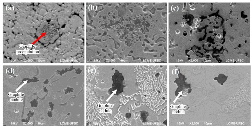
Figure 1 shows the effect of the sintering temperature on the formation of the graphite reservoirs for the Fe + 0.6%C + 3%α-SiC composite sintered for 60 min. The images show that the increase in the temperature causes an expansion of the reservoirs. At the lowest temperatures, 950 and 1000 °C (
Figure 1a,b), it is possible to see the initial reaction between SiC and the metallic phase. Especially for the sample sintered at 950 °C, the SiC particle can still be identified, and the beginning of the formation of graphite is observed in the centre of the particle (indicated by the red arrow in
Figure 1a). For the sample sintered at 1050 °C (
Figure 1c), the reservoir formation is in an intermediate stage, and the SiC particle is no longer visible. However, the reservoirs formed are still tiny at this temperature. Finally, for the temperatures above 1100 °C, the reservoirs are larger and in an advanced formation stage (white arrows in
Figure 1d–f).
The increase in the reservoir size is not necessarily caused by the merging of the graphite phase (carbon transfer between reservoirs). Instead, the pores’ curvature radius is much smaller than the internal radius of curvature of the graphite reservoirs. Therefore, it favours the transfer of vacancies from the residual pores to the neighbouring graphite reservoirs. As a driving force, this phenomenon reduces the free energy resulting from the transfer of the vacancies of the pores with a small radius of curvature (those eliminated) to the graphite reservoirs with a greater curvature radius.
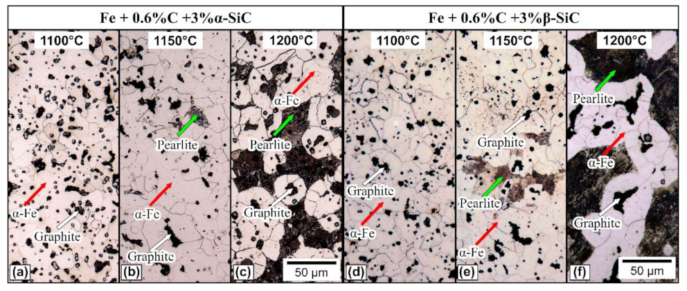
Since the complete formation of the graphite reservoirs is only observed for the sintering temperatures above 1100 °C, the focus of this work was on the highest temperatures (1100, 1150 and 1200 °C). The typical microstructures of these composites are shown in
Figure 2. The composites sintered at 1100 °C (
Figure 2a,d) presented graphite reservoirs homogeneously dispersed through the matrix (indicated by white arrows), a completely ferritic matrix (α-Fe), indicated by the red arrows, and the primary porosity, resulting from the sintering process. During sintering, because of the SiC dissolution in the matrix, α–Fe is stabilised by Si enrichment of the matrix. The low solubility of carbon in α–Fe prevents further dissolution of carbon, which remains “trapped”, forming the graphite reservoirs.
The composites sintered at 1150 °C (
Figure 2b,e) presented very similar microstructures to those treated at 1100 °C. However, a small portion of pearlitic regions can be identified (indicated by the green arrows). Since γ-Fe presents a much higher solubility of carbon than α-Fe, the formation of perlite indicates that the matrix dissolved more carbon before the stabilisation of α-Fe around the reservoir. Furthermore, a higher formation of pearlitic regions can be observed in the composites sintered at 1200 °C (
Figure 2c,f) than in the ones sintered at 1150 °C. The results suggest that even higher dissolution of carbon in the matrix occurred, caused by the higher diffusion coefficient of the elements in iron at this temperature.
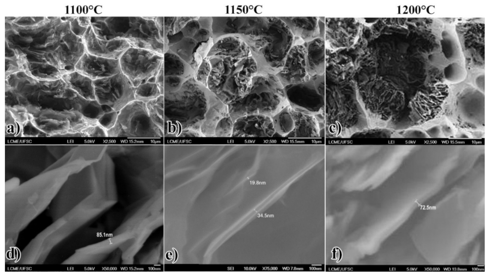
Figure 3 shows low and high magnification FEG-SEM fractographies of the Fe + 0.6%C + 3%α-SiC composites. It shows that the reservoirs are formed by many graphite sheets relatively separate from each other. For samples sintered at 1100 °C and 1150 °C (
Figure 3a,b), the carbon sheets resulting from the dissociation are arranged randomly and with greater spacing between sheets. For the specimen sintered at 1200 °C (
Figure 3c), the graphite sheets are closer and more organised, positioned radially within the reservoir. The sintering temperature does not seem to affect the thickness of the graphite sheets, which have thicknesses of tens of nanometers, varying between themselves at the same temperature (
Figure 3d–f).
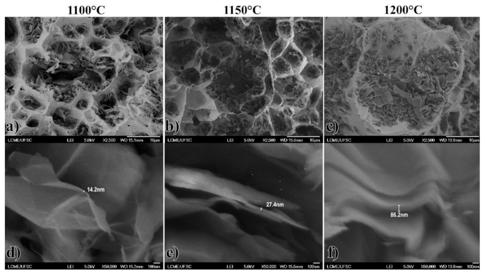
Figure 4 shows the fractographies of the Fe + 0.6%C + 3%β-SiC composites. It was not possible to observe the influence of the sintering temperature on the organisation, distribution, and thickness of the graphite sheets in the specimens. As shown in
Figure 4b,d,f, the thickness of graphite sheets can vary from a few nanometers to dozens of nanometers for these samples, and different thicknesses were found between the sheets of the same reservoir.
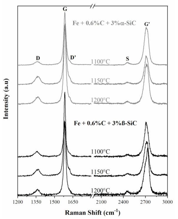
Figure 5 presents the typical Raman spectra of the graphite reservoirs generated from the SiC dissociation at different sintering temperatures. All the spectra show the same bands. The first-order Raman spectra of the reservoirs present the G band at approximately 1580 cm
−1, which is the only first-order band observed in a single graphite crystal [
33]. The presence of the D band at ~1360 cm
−1 and the D’ band at ~1620 cm
−1 indicates the formation of disordered graphite in the reservoirs. These bands are related to structural disorders and defects of the graphitic material, such as punctual defects, pores, and edges [
33,
34,
35]. In addition, the spectra also present the second-order G’ band, which appears in the 2500–2800 cm
−1 range. This band is also typical of graphitic materials. After fitting the adequate Lorentzian peaks for the first order D and G bands, the results are present in
Table 2.
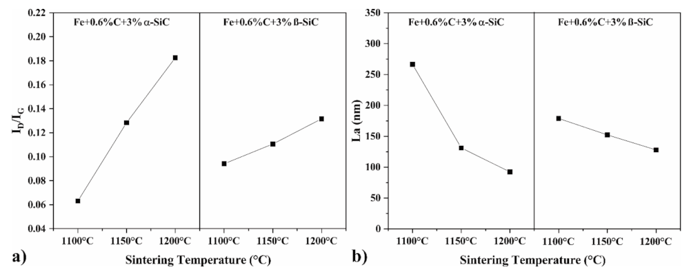
A typical parameter used to evaluate the crystalline order of carbon materials is the intensity ratio of the D and G bands, I
D/I
G. Since the intensity of the D band increases with the presence of crystalline defects, a higher I
D/I
G ratio indicates a higher crystalline disorder in the graphite structure [
33,
36]. After fitting the adequate Lorentzian function for each band,
Figure 6a shows that the I
D/I
G ratio of the Raman spectrum increases with the sintering temperature for both SiC polytypes. The composites with α-SiC presented a higher I
D/I
G ratio range, from ~0.06 to ~0.18, while those with β-SiC presented a range from ~0.09 to ~0.13.
It is possible to correlate the I
D/I
G ratio with the crystallite size (L
a) of the graphite. L
a can be calculated with the equation L
a (nm) = (2.4 × 10
−10) λ
4 (I
D/I
G)
−1, where λ is the wavelength of the laser (514.5 nm) [
37]. This correlation has been used for edge defects in nano graphite, and the results consist of an average measure of several edge structures present in bulk nano graphite [
33,
34,
38]. The calculated crystallite sizes for the samples are present in
Figure 6b. It shows that the graphite reservoirs contain nanocrystalline material, and crystallite size decreases with higher sintering temperatures. The graphite reservoirs generated from α-SiC presented a wider range of the crystallite size value, from ~266 nm for the material sintered at 1100 °C to ~92 nm for the material sintered at 1200 °C. These calculations assume that the D-band arises mainly from crystallite boundaries, so the calculated values may be smaller than the actual value of L
a due to other defects. Nevertheless, the results indicate that it is possible to control the graphite structure presented in the graphite reservoirs by controlling the reaction temperature.
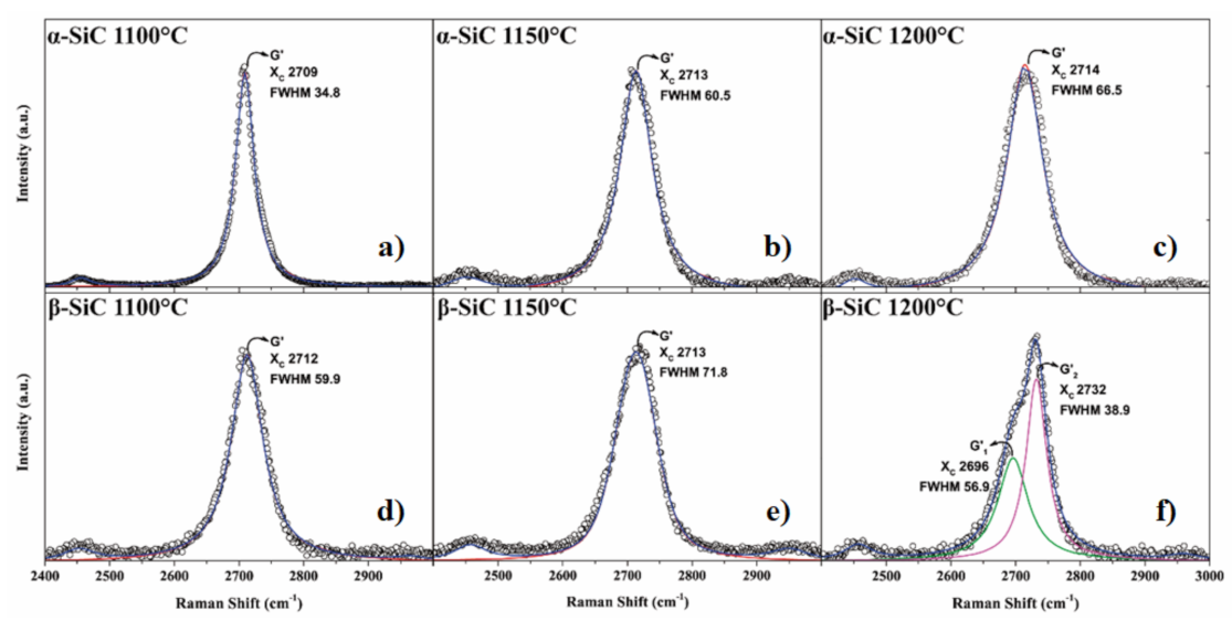
Figure 7 shows the Raman spectra of the graphite reservoirs in the range between 2400 and 3000 cm
−1, evidencing the G’ band. It is possible to observe significant changes in the shape of the G’ band with the sintering temperature. The shape and position of the G’ band present information regarding the stacking order of the graphene layers in the graphite structure, which is susceptible to structural changes along the c axes [
39].
The Raman spectra had a single G’ band for the graphite reservoirs generated from Fe + 0.6%C + 3%α-SiC (
Figure 7a–c). The FWHM value increases with the sintering temperature in these samples, ranging from 34.8 to 66.5 cm
−1. In the Raman spectrum, a single G’ band (also called G’
2D) is typical for two-dimensional graphite. For example, the FHWM value for single-layer graphene is close to 30 cm
−1. Higher FHWM values suggest the formation of 2D turbostratic graphite in these composites [
34,
40]
For the graphite reservoirs generated from the Fe + 0.6%C + 3%β-SiC, the Raman spectra also indicate a 2D turbostratic graphite formation for the sintering temperatures of 1100 and 1150 °C (
Figure 7d,e) because they also presented a single G’ band with a broad FHWM value. However, the G’ band of the graphite reservoir formed at 1200 °C consists of two components, G’
1 and G’
2, centred at 2696 and 2732 cm
−1, respectively. The existence of two G’ peaks, G’
1 and G’
2 (also called G’
3DA and G’
3DB), are typical for three-dimensional graphite samples [
33,
40], which suggests the formation of a 3D graphite for this sintering temperature.
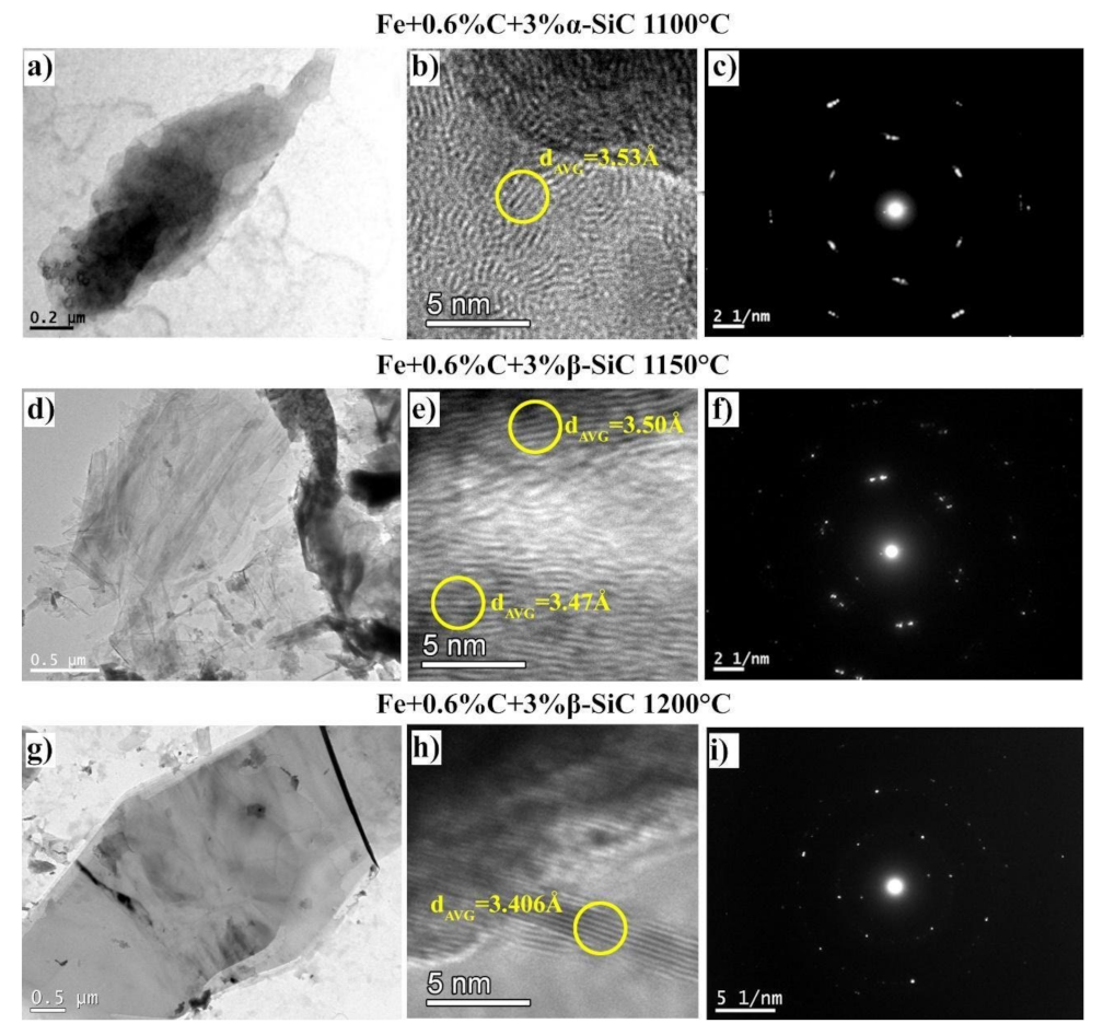
The analysis of the graphite by TEM allows for studying the isolated sheets of the graphite reservoirs. The characterisation made by Raman was performed in the volume of the reservoirs, covering several sheets. Therefore, based on the Raman spectra, three different conditions were selected for TEM: (1) Fe + 0.6%C + 3%α-SiC composite sintered at 1100 °C because its Raman spectrum indicated the lowest degree of defects, (2) Fe + 0.6%C + 3%β-SiC composite sintered at 1150 °C, and (3) Fe + 0.6%C + 3%β-SiC composite sintered at 1200 °C because its Raman spectrum suggests the presence of 3D graphite.
Figure 8a,d,g show the morphology of the sheets, which are very similar among them. The corresponding SAED patterns (
Figure 8c,f,h) were indexed as the (002), (100) and (110) planes of the hexagonal polycrystalline graphite (P6
3/mmc symmetry). The HRTEM images (
Figure 8b,e) demonstrate the atomic organisation of the carbon atoms. The wave-like appearance of the (002) planes in the HRTEM images suggests the formation of turbostratic 2D graphite in these samples. The interplanar distance along the c-axis (d
002) measured from the HRTEM images indicates d
002 from 3.47 to 3.53 Å for the carbon of the Fe + 0.6%C + 3%α-SiC composite sintered at 1100 °C and from 3.43 to 3.50 Å for the carbon of the Fe + 0.6%C + 3%β-SiC composite sintered at 1150 °C. For the β-SiC composite sintered at 1200 °C, the d
002 measured from the HRTEM image and SAED pattern was ~3.40 Å for this graphite sheet (
Figure 8h,i, respectively). This value is smaller than the d
002 obtained from the other conditions. However, it is still slightly larger than the d
002 of a typical highly crystalline graphite structure (~3.34 Å), which indicates that this graphite sheet still presents a certain degree of crystalline disorder.
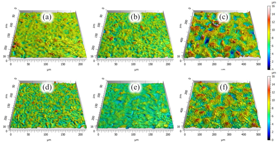
Qualitative analysis of the composite topographies through axonometric projections of the surfaces is shown in
Figure 9. All the composites presented typical morphological characteristics of surfaces generated by the powder technology processes, e.g., large plateaus and valleys homogeneously distributed (pores), except for the composite Fe + 0.6%C + 3%β-SiC composite sintered at 1200 °C (
Figure 9e). In this condition, the surface is significantly rougher, with prominent peaks homogeneously dispersed throughout the surface. The surfaces of the composites Fe + 0.6%C + 3%α-SiC sample sintered at 1150 °C and Fe + 0.6%C + 3%β-SiC composite sintered at 1100 °C (
Figure 9b,c, respectively) also appear to have some more pronounced peaks but they are much more spaced apart.
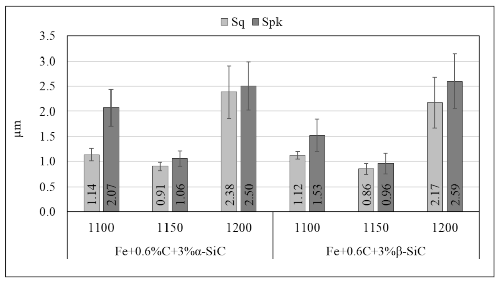
In a quantitative analysis of the topography, the graph in
Figure 10 presents the topographic parameters Sq and Spk. The composite surfaces sintered at 1150 °C are smoother, presenting values of Spk (reduced peak height) equivalent to the values of the root mean square roughness (Sq).These features are interesting for tribological contacts because they are related to increasing the real contact area. On the other hand, the composites sintered at 1100 °C presented an Sq slightly higher with peaks significantly higher than the roughness. For the composites sintered at 1200 °C, the roughness is more than twice of the composites sintered at 1150 °C, which is related to higher tribological contact pressures. However, the valleys between these peaks can also work as solid lubricant reservoirs.
Like the composite microstructures and graphite characteristics, the surface roughness also strongly affects the tribological behaviour of materials. Therefore, discussion about the tribological results will be based on all these aspects. Additionally, the tribological behaviour of the composite Fe + 0.6%C + 3%α-SiC sintered at 1150 °C was used as a reference because it was discussed in previous work along with the results associated with only the metallic matrix Fe + 0.6%C (COF 0.33, wear rate 3.5 × 10
−5 mm
3/Nm) [
31].
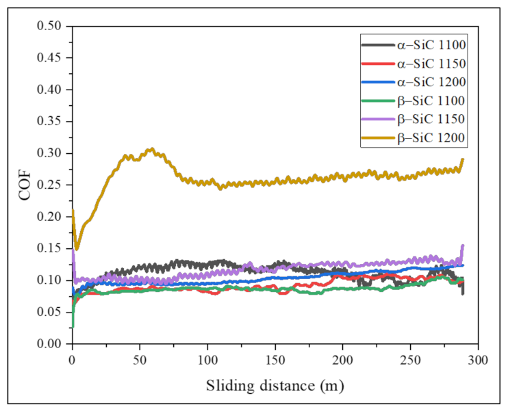
Figure 11 presents the typical friction coefficient evolution versus sliding distance of the tribological tests. All the specimens induced friction coefficients of around 0.1 or less (self-lubrication), including the composite Fe + 0.6%C + 3%β-SiC sintered at 1200 °C because, although the friction coefficient in the graph is higher, for some tests, it was the lower. This scatter behaviour can be observed by the large standard deviation in
Figure 12. When the average friction coefficients are compared, it is observed that the composites with similar topographies presented similar results, except for Fe + 0.6%C + 3%β-SiC sintered at 1200 °C, in which the composite-containing 3D graphite reservoirs induce a higher friction coefficient than those containing 2D turbostratic graphite. The greater d
002 distances and plane misorientation of the 2D turbostratic graphite and, consequently, the lower interaction between the crystalline planes results in low shear stress, promoting the lower friction coefficients observed.
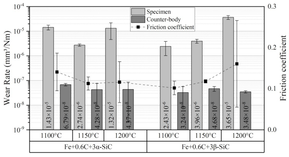
Figure 12 also shows the wear rate of the specimens and respective counter bodies. Although the composite Fe + 0.6%C + 3%β-SiC sintered at 1100 °C presented a higher wear resistance, it was statistically similar to those sintered at 1150 °C (~10
−6 mm
3/Nm), while composites sintered at 1200 °C and Fe + 0.6%C + 3%α-SiC sintered at 1100 °C presented a wear rate of 10
−5 mm
3/Nm in order of magnitude. The wear rates of counter bodies are statistically similar among the different conditions, and they are two or three orders of magnitude lower (~10
−8 mm
3/Nm). This result was expected because the hardness of cylinders was around 750 HV (AISI 52100 steel), and they were in contact against the specimens with ~210 HV. Therefore, the sintering temperature of 1150 °C promoted the best tribological performance. This temperature was suitable for forming a ferrite perlite matrix and well-distributed 2D turbostratic graphite reservoirs. Additionally, these composites present smoother surfaces, resulting in the best performances and repeatability.
In a previous work [
31], we compared the performance of one of these self-lubricant composites with that of nodular cast iron. As the cast iron presents a similar microstructure, except for the 3D graphite reservoirs, the worse tribological performance was attributed to it. However, a completely different process produces the nodular cast iron, which introduces other variables to the system. With the use of the β-SiC, it was possible to generate different graphite structures using the same carbide precursor and the same processes, which makes the comparison in performance much more adequate. The results obtained in this work confirm that the presence of the 2D turbostratic graphite is a key benefit to the tribological performance of these iron-based self-lubricant composites, providing lower friction coefficient and wear rates.
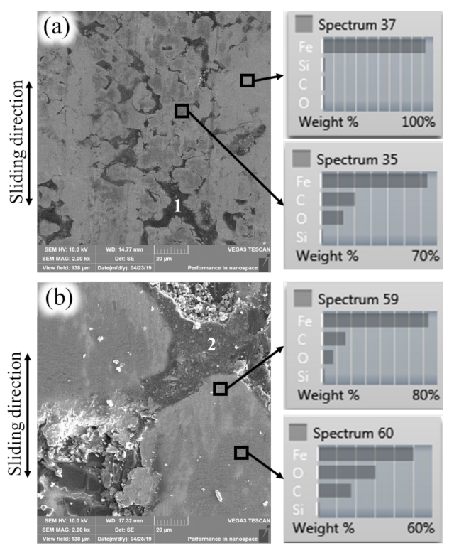
By analysing the wear marks of the specimens in the SEM-EDS, it was observed that sliding wear was the prevalent wear mechanism. The composites sintered at 1100 and 1150 °C (
Figure 13a) present similar features among them, while those sintered at 1200 °C (
Figure 13b) present different ones. According to that observed in the microstructures (
Figure 2) and the topographies (
Figure 9), specimens sintered at 1100 and 1150 °C contain small graphite reservoirs homogenously distributed in the metallic matrix, denoted by “1”
Figure 13a. These reservoirs on the surface provide a solid lubricant to the tribological contact to form tribolayers (Spectrum 35 in
Figure 13a) composed of wear particles and solid lubricants that were comminuted, mixed, and sheared along with oxidative processes (reactions with the atmosphere). On the contrary, on the composites sintered at 1200 °C, it was not possible to observe solid lubricant reservoirs “opened” on the wear marks surface, probably because the contact stress generated on the rougher surface is enough to plastically deform the metallic matrix and “close” the solid lubricant reservoirs (denoted as “2” in
Figure 13b). However, solid lubricants and wear particles’ remnants stay trapped in the valleys working as a materials reservoir for the tribolayers formation, as observed in Spectrum 60 of
Figure 13b.
A continuous formation and degradation process of the tribolayers govern the tribological performance of the composites.
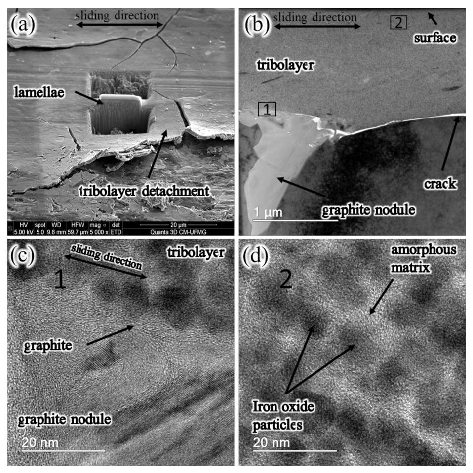
Figure 14 shows a detailed analysis (FIB-FEG) of the tribolayers in the degradation stage. In
Figure 14a, it is possible to observe cracks and the detachment of the tribolayer. In addition, it is possible to see where it was removed in the lamellae for FEG analysis. The cross-section indicated a tribolayer around 1 μm thick; it is also possible to see a graphite reservoir below the tribolayer (
Figure 14b).
The interface between the graphite reservoir and the tribolayer (denoted by 1 in
Figure 14b) is shown in
Figure 14c, where the graphite carbon planes aligned with the sliding direction. At the same time,
Figure 14d presents a typical tribolayer structure (denoted by 2 in
Figure 14b) formed by iron oxide nanoparticles embedded in an amorphous matrix. Therefore, when the tribolayer reaches around 1 μm thick, along with the amorphisation process, the results indicate that the detachment of these tribolayers occurs, exposing an aligned graphite-rich tribolayer that provides low friction coefficients and wear rates.

 ,
, 


