Characterization of In Vivo Damage on Retrieved Total Shoulder Glenoid Liners


1
Department of Biomedical, Industrial, and Human Factors Engineering, Wright State University, 3640 Col Glenn Hwy, Dayton, OH 45435, USA
2
Materials and Manufacturing Directorate, Air Force Research Laboratories, Wright-Patterson Air Force Base, Dayton, OH 45433, USA
3
Department of Orthopaedic Surgery, Georgia Reagents University, Augusta, GA 30912, USA
*
Author to whom correspondence should be addressed.
Lubricants 2022, 10(8), 166; https://0-doi-org.brum.beds.ac.uk/10.3390/lubricants10080166
Submission received: 25 May 2022
/
Revised: 7 July 2022
/
Accepted: 20 July 2022
/
Published: 22 July 2022
(This article belongs to the Special Issue Synovial Lubricated Joints—Devices and Mechanical Behavior)
Abstract
:An attempt was made to retrieve glenoid liners from revision surgery to undertake a retrospective study to measure the resulting in vivo damage. Since the glenoid liners are circumferential, the curvature changes at every point in the component, an “assisting arm” was designed to hold the liner firmly, thus allowing accurate microscopic measurements. We characterized the damage in terms of pitting, embedded debris, complete fracture, abrasion, deformation, delamination, burnishing, grooving, and scratching that took place mutually exclusively. This study of 26 liners showed embedded debris was the most underrated damage mode found on the liners, followed by pitting and abrasion, representing 65.2% and 52.2% of the liners, respectively. The prevalence of pitting in over half the samples examined is indicative of free-radical oxidation, resulting in a decrease in physical strength from morphological changes in the microstructure. These may initiate from different pathways, however, they may interact with other processes in which other damage initiates and grows, resulting in higher damage causing premature failure due to wear. A probabilistic approach was developed to generate survival time for these liners and may provide a statistical removal time of the glenoid liners in the future.
1. Introduction
In a previous effort, published in Lubricant 2016, the authors presented an approach to quantitatively determine in vivo damage in glenoid liners. However, in that effort, the results obtained were a function of the observer performing the quantitative analysis utilizing the damage characterization tools, such as an optical microscope. A liner surface was segmented in terms of four quadrants and associated wear damage was represented in terms of available methods. A new composite damage parameter was proposed therein, that evolved from observations made on nine liners. A retrospective study of 26 Ultra-High-Molecular-Weight-Polyethylene (UHMWPE) glenoid liners that were retrieved during revision surgery has been performed in this paper. Twelve of these liners were used in the conventional total shoulder arthroplasty (TSA) and 11 in reverse TSA procedure, while three were assembled with head and liner combination and could not be removed. Additional hardware from the original implant was included in nine of the cases presented. All liners presented were made with UHMWPE except one liner, B2B10 (naming convention below), which was a UHMWPE-metal hybrid. Information concerning patient demographics, duration in vivo, and factors leading to revision are limited. In addition, no in situ imaging was available to indicate the amount of damage prior to removal during the revision procedure. The degree of wear for each liner was highly variable, with specific liners showing significant damage and others showing only light damage. Since there are no standards to retrieve and characterize in vivo damage in implants, the objective of the study was to first collect as many liners as possible, given only fewer TSR surgery occur, secondly use the laboratory equipment to characterize and quantify damage, as previously reported by the authors [1,2]. The knowledge gained from this research would enable reverse engineer liners to prevent specific damage mechanisms.
The naming convention used in this investigation separates the two lots of samples B1 and B2 followed by liner number B from i to n (i from 1 to n represents number of sample). Table 1 shows the initial overview and summary of the liners examined.
2. Background
Although various joint replacement procedures occurred and are discussed in this paper [1,2,3,4,5,6,7,8,9,10,11,12,13,14,15,16,17,18,19,20,21,22,23,24,25,26], the liners were characterized for the following, ankle [12], knee [2,5,11,16], hip [3,6,7,8,10,13,15] and shoulder [1,4]. Many of these studies are relative via visual observation or through an optical microscope. Only a few studies exist that characterize liners thoroughly as done in [1,2,12]. TSA is a total joint replacement [1,4] primarily used to restore shoulder mobility in patients with a degenerative disease, arthritis, and traumatic injury [1]. The number of TSA procedures performed in the United States has increased continually from 1999 and beyond [1]. There are two procedures in which TSA is performed. One method, referred to as traditional shoulder arthroplasty, is used to correct pain and decreased shoulder mobility secondary to osteoarthritis. The second approach to performing TSA is known as the reverse method. This method is indicated for osteoarthritis and pain caused by rotator cuff injury, which causes supraspinatus muscle impingement between the humerus and acromion process through the natural upward tension exerted via the deltoid muscle. The UHMWPE liner is commonly considered the limiting factor in the long-term success of total joint replacement surgery [2,3], therefore, it has been investigated earlier and in the present study. In a study performed by Denard et al. in 2013, it was found that the survivorship of TSA after 10 years in patients aged 55 and younger was only 62.5% [4]. Even though shoulder joints are different in that the way they are loaded differs from the compressive loads as they occur in the ankle, hip, knee, and other joints, the compression obtained in the shoulder joint fades away as the hand pulls the humeral head naturally. Therefore, with such low long-term success, the wear of the UHMWPE liner must be characterized to improve its resistance to these damage modes.
3. Experimentation and Results
3.1. Visual Examination
The as-received liners were retrieved following the procedures outlined in [1] and packaged in two separate clear containers with no apparent damage to the outside. Lot B1 contained 12 liners, while B2, 14 liners (Table 1). Each UHMWPE liner was in a plastic sealable bag and paired with metallic implant components in a larger bag when applicable. Visual inspection of each of the components was performed, categorizing the liners based on nine different wear modes common to UHMWPE liners. These wear modes were delamination, pitting, abrasion, scratching, burnishing, deformation, embedded debris, complete fracture, and grooving [2,5].
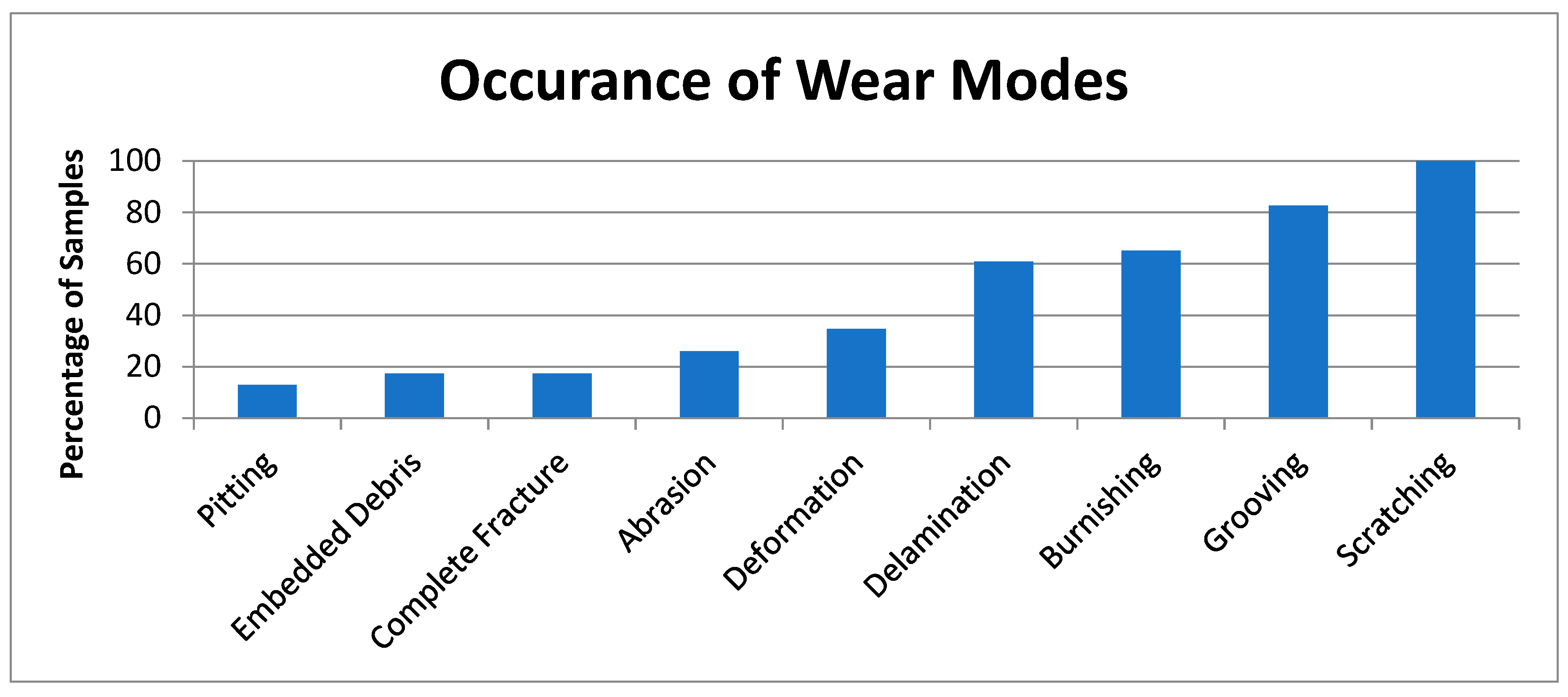
Delamination is the separating of layers of the UHMWPE due to cyclic fatigue loads. Repeated loading and unloading events cause intermolecular bonds within the liner to break, leading to the material separating into layers. Of the liners examined, 14 liners or 60.9% had delamination characteristics visible without magnification (Figure 1a). Even though we do not know the time when the devices were revised, it is quite possible that the devices replaced sooner than 5 years may have a limited amount of delamination.
Pitting refers to the craters that form in the UHMWPE caused by oxidation and crystallization of material, accelerated by environmental factors. Pitting corrosion was found in 13% of the liners during a visual examination. Figure 1b shows an example of surface pitting on an articulating surface.
Abrasions are defined as multiple surface scratches in the same orientation made by one surface rubbing on another. Due to excessive scratching in some instances, it is difficult to differentiate single scratch events from abrasions. Abrasions were found in 6 liners or 26.1% of the samples examined. Figure 1c shows an example of abrasion wear.
Scratching is a damage mode where the surface is permanently marked or scored by a foreign object. It is the most common mode of wear in UHMWPE liners due to unavoidable microscopic surface irregularities present in all materials. Scratching of the articulating surface was found in 100% of the samples examined. Figure 1d is an example of surface scratching on the liner articulating surface.
Burnishing is an apparent shininess of a surface due to plastic deformation caused by excessive loading and unloading in conjunction with fatigue and repeated loads/stresses. On the implants examined, burnishing was seen in localized areas with apparent high-stress points. Burnishing was present in 15 liners or 65.2% of the liners examined. Figure 1e shows an example of surface burnishing.
Deformation is defined as exaggerated wear changing the shape of the overall material. Although deformation can occur from a high-stress event, constant wear can cause material deformity and lead to absolute failure of a liner. Deformation was present in 8 liners or 34.7% of cases examined. Figure 1f shows deformation from excessive wear.
Embedded debris is described by any foreign material that becomes attached to the surface or lodged into the structure of the glenoid liner. These foreign materials have various origins, including metal fragments from respective replacement components, components of bone, or materials used during prosthesis implantation. Limited embedded material was visible without magnification. Some embedded debris was immediately apparent in regions with grooving and delamination due to the increased surface roughness, however, micro-debris on the articulating surface was rarely noted in the absence of optical magnification. Of the liners examined, 17.4% had embedded material seen within the UHMWPE. Figure 1g shows an example of embedded debris in the implant.
Complete fracture of the liner is caused by extensive propagation of wear transitioning to fatigue cracking propagating to critical size and unable to sustain the applied load. This may also occur due to overload due to high-stress events (from falls or terrain issues) in addition to malalignment secondary to aseptic loosing [6]. As damage infiltrates the inner layers of the UHMWPE, it eventually spans across the inner surface and spreads orthogonally in either direction. Continued loading and fatigue accelerate the fracture process and lead to the failure of the liner. One liner examined displayed complete fracture, causing separation into two pieces. This liner is detailed in Figure 1h. In total, complete fracture through the liner was noted in 17.4% of the liners.
Grooving is a more aggressive form of scratching that occurs when a floating or fixed foreign particle is dragged across or caught in the articulating surface. The motion of the shoulder joint can accelerate the wear leading to deep grooves throughout the articular surface. With the addition of fatigue/sliding loading over time, these grooves have the potential to propagate into a fatigue crack over time. There were 20 liners that exhibited grooving, representing 86.9% of the samples examined.
Mutually exclusive percent wear mode occurrences in the liners are presented in Figure 2.
3.2. Stereomicroscopy
Studies documenting the wear of UHMWPE liners using general light microscopy have traditionally had restricted abilities due to limitations of the microscope and the inability to clearly image curved surfaces at high magnifications. The wear of liners is generally documented from either the edge articular surface or back surface of the liner [7,8]. During this study, a novel universal arm was designed to hold liners in place during microscopic examination. The arm allowed the liner articular surface being inspected to be oriented perpendicular to the objective lens of the microscope in any configuration necessary for clear-focused inspection. An inverted microscope manufactured by ‘Motic’ model ‘AE2000MET’ (Motic North America, San Antonio, TX, USA) was used during this study. This microscope has a base magnification of 10×. Digital images were captured using a ‘Lumera Inifinty 1’ integrated microscope camera. Figure 3 shows the setup of the universal arm used to hold the liners in place.
The initial goal of stereomicroscopy was to characterize and examine non-worn surfaces to distinguish the fundamental topography of the articular surfaces (Figure 4). The initial inspection of the liners showed microdamage in the form of scratches on all liners examined. On reverse TSA liners and select traditional TSA, machining ridges were present, spiraling out from the center of the articulating surface toward the edges (Figure 5a). At locations where scratching was present, the damage in many cases had propagated into the formation of a groove. Figure 5b shows a typical example of a machined surface with scratch and groove formation. Figure 4 and Figure 5b also show grooves forming an abrasion of the edge of a liner articular surface.
Similar examples of damage were seen throughout other liners examined. In some instances, it was accompanied by third-body particles not immediately apparent in the visual examination. The origin of these grooves was not apparent, however, since many humeral heads accompanying the liners did not have obvious damage. For an example of some of the humeral heads associated with the liners, refer to Figure 5c.
Another type of wear examined in scrutiny during stereomicroscopy was pitting corrosion. Pitting (Figure 5d) in polymer components is often associated with free-radical oxidation [9,12]. In the visual examination process, pitting was observed on 26.1% of the liners. Stereomicroscopy revealed insolated regions of pitting on liners that had not been previously found. These results are indicative of free-radical oxidation of the liner, leading to corrosion from oxygen acting as an anode within the UHMWPE. See Figure 4 for an example of pitting found in the liners.
Nearly all wear modes were underrated during visual examination, and it was clear that microdamage was present throughout the articular surface that was not otherwise apparent in visual exam. Pitting was the most underrated form of damage physically occurring in 52.2% of the liners, followed by embedded debris occurring in 65.2% of the liners. The prevalence of pitting in over half the samples examined is indicative of free-radical oxidation, resulting in a decrease in physical strength from morphological changes in the microstructure. Similar results were obtained [7], where 75 liners were examined and it was found that a majority of the liners had pitting present with an average damage score of 7.4, using evaluation methods defined by Hood et al. [1,2,5,10]. The corrected increase in embedded debris gives an origin to the amount of grooving and scratching present. Particles enter between the articulating surfaces of the joint and are dragged between the ball and liner in randomized motion as the joint is subjected to tension and compression. These particles can range from bone cement, liberated PMMA fragments, or metal fragments from the ball [11].
In this research, we were able to compare the visually observed damage features with those of stereomicroscopy. Figure 6 shows the corrected change in the tabulated wear data from the visual examination to stereomicroscopy. The percentage increase between examination methods is shown, as well as the physical percentage of liners where the damage was previously overlooked in Figure 6.
3.3. Hardness
The hardness of a material is representative of its overall integrity and a measure of how well the material has retained its physical properties since its original manufacturing. The hardness of UHMWPE can be affected by numerous factors, including time in vivo, oxidation, crystallinity, subjected stresses, and degree of wear [12]. Extensive tribological research has focused on increasing the hardness, elastic modulus, and crystalline regions of UHMWPE while maintaining low brittleness [12]. Currently practiced methods of increasing hardness during manufacturing include γ-induced crosslinking, post-process annealing, and surface coatings [13,14]. Increasing UHMWPE hardness has been fundamental in improving joint mobility and function by allowing a decreased liner thickness with an increased ball size [15].
The ideal region to measure the hardness on the UHMWPE glenoid samples is on the articulating surface because it develops the most wear over time and is most responsible for the longevity of the liner. The durometer used to measure hardness, ‘Fowler Shore D durometer’ (Fred V. Fowler Company Inc., Canton, MA, USA) requires a relatively flat surface to create a microindentation. Due to the unique curvature of the glenoid liners, the only area suitable for testing was the back and side of the liners, which is contained within a base plate while in vivo. The hardness of each liner was tested at three separate points and the average value from each was calculated. The Shore D scale was used as the unit for the measured hardness of hard polymers, it is unitless and covered in ASTM/ISO (D2240/868), respectively, ranging between 0 and 100. See Table 2 for the results from the hardness testing and Table 3 for the compiled average hardness and standard deviation.
3.4. Confocal Microscopy
As with general light microscopy, confocal microscopy has many of the same complications of imaging the curved articular surfaces of the glenoid liner. These issues are further compounded since the universal arm used to hold the liners during stereomicroscopy would not fit on the stage of the confocal microscope, and the diameter of the objective lenses was larger than that of a stereomicroscope. The confocal microscope used during this study was an ‘Olympus Fluoroview FV1000’ (Olympus Corporation, Tokyo, Japan) using a combination of DAPI and Cy5 lasers as well as DAPI and FITC lasers. The stage of this microscope is specialized for viewing biological microscope slides. Both the traditional and reverse liners were viewed by placing them within the slot on the stage that houses a backlight. The main characteristics of interest in examining the liners by the confocal microscope were the depth of delamination and pitting as well as any third-body particles present in the damaged regions. The depth was calculated by arranging the stage of the confocal microscope at the vertical position just before where the damage was visible. The liner was then imaged in layers as the stage moved upward until the damage was no longer visible. The distance that the stage traveled vertically is equal to the total depth of the damage present. Figure 7 shows examples of delaminated regions imaged through the microscope. Figure 8 shows an example of surface pitting present.
From the confocal microscopy performed on the liners, it was determined that the average depth of delamination was 567 μm. Furthermore, the average depth of the pit was found to be 116 μm. Additional analysis can be performed using these data in conjunction with oxidation index testing in order to better estimate depth propagation as it relates to the time of in vivo exposure.
3.5. Oxidation Analysis
As UHMWPE components age, it is common to develop changes in chemical composition and subsequent material strength properties. Propagation of liner damage in the form of delamination, cracks, and sub-surface hardness is directly related to the excessive oxidation of UHMWPE [16]. During manufacturing, many liners are subjected to γ-irradiation to create cross-linkages between amorphous phases and create Highly-Crosslinked-Ultra-High-Molecular-Weight-Polyethylene (HCUHMWPE) to improve wear resistance [17]. Unfortunately, this γ-irradiation results in the creation of free-radical oxygen production, accelerating the wear and decreasing the physical properties of the liner. Post-process annealing performed on the liners is aimed at suppressing free-radical production but decreases carbon-to-carbon bonds, resulting in chain scissions along the molecular backbone [18]. In addition, vitamin E, an antioxidant, has been infused in PE liners as a method of reducing radical oxygen in recent efforts to control free radicalization [16].
In the 23 of 26 samples presented during this study, the goal was to take these liners and place them in a Fourier-Transform-Infrared-Spectrometer (FTIR) for quantitative analysis of oxidation. The apparatus used during this procedure was ‘ThermoScientific Nicolet 6700 FT-IR’ (Waltham, MA, USA). Analysis of the liners was not completed, however, due to the size of the liners not fitting between the sample-securing screw and the germanium FTIR analysis window. See Figure 9 for limitations of the FTIR analysis since we were not to destruct the liners as the machining UHMWPE is quite complex.
3.6. Probabilistic Simulations
The modeling and prediction of characteristic UHMWPE wear present a challenge for several reasons. Patient activity level, weight, health conditions, mal-alignment, and manufacturing conditions also play a role in the overall success of the shoulder joint and polyethylene liner. Quantifying patient-specific metrics requires extensive statistical analysis and surveying, which is not possible for this study. In addition, another challenge faced during the wear simulation was not having time to failure and time in-vivo for each of the liners examined. Age estimations may be supplemented into analysis using data from oxidative analysis later, however. Since all the liners were from revision surgery conducted over the course of time, not known for this study, it is likely that the oxidation damage may continue to accrue during storage and may require a vacuum capability that is beyond the scope of this investigation.
Monte Carlo simulations are designed to predict the probability of various failures by considering interactions of individual components across various events and weighing the probability of overall failure. Meaningful risk information is gained by randomly repeating sampling events and compiling the results [19]. Monte Carlo analysis has been performed throughout the medical field in joint and dental implant specialties, as well as prediction of failure for in-hospital medical equipment [20,21].
For this study, Goldsim Software Inc. (Seattle, WA, USA) provided an academic version of their program for free. This software has been used to model and predict device failure across many industrial and medical specialties. Goldsim Software uses ‘realizations’ in the form of a specified number of separate simulations that are conducted for a predetermined number of years. In this study, each realization represents a separate liner being simulated to failure. The results from each liner are tabulated and combined. The instances of failure due to each damage mode can then be reexamined individually. The liner simulation duration was defined through 22 years since manufacture so that all the liners could be seen out to failure. Scratching and grooving were defined as the Poisson process resulting in a wear rate of 1 × 10⁻⁵ per day and 5 × 10⁻⁵ per day, respectively. Delamination, pitting, abrasion, deformation, complete fracture, and embedded debris were defined with Weibull Mean-Life and Slope Factor. Where a Poisson process is considered to occur at a constant rate, Weibull Mean causes an event to occur around a specified time and then progresses to failure at a defined slope rate. Multiple simulations were run, adjusting the rate at which damage occurs for the results to resemble known failure statistics. The average duration to failure of the liners was 8035.5 days from 100 realizations. Table 4 shows the average operational availability of the liners at 5% and 95% confidence bounds. Figure 10 represents the projected failure curve of the liners with respect to time. Figure 11 and Figure 12 are the results as a probability distribution and complementary cumulative distribution [25,26].
From these results, it was inferred that the mean time to failure increased linearly as scratching and grooving occurred within the liner. After the scratching and grooving were complimented with third-body particles, the rate of failure increased exponentially as additional wear modes manifested. This tended to mirror the trends of the 23 liners damaged in this study despite there being no in-situ duration information available. Since we did not know the time at which the revision occurred, Kaplan–Maier survivability for the glenoid liner was not possible. However, such data may be recorded to plot the behavior.
4. Conclusions
The UHMWPE liner is prone to damage accumulation through exposure to in vivo conditions. Resistance to various damage modes is a key factor in the long-term survival of TSA. Damage is usually characterized visually to conclude gross wear damage clinically. However, in order to characterize and quantify damage, stereomicroscopy, confocal, and other tools are used. Results from this investigation of 26 retrieved liners revealed that the failure of the liner was a multifactor process. Nine wear modes, namely delamination, pitting, abrasion, scratching, burnishing, deformation, embedded debris, complete fracture, and grooving, were examined during this investigation. Each of the modes was found to be mutually exclusive. As the length dimension of the damage increased, those features were visually noticeable, for example, scratching, representing 100% of the liners examined. Scratching follows a pathway of progressively more invasive wear modes, followed by pitting and abrasion. This study of 26 liners showed embedded debris was the most underrated damage mode found on the liners followed by pitting and abrasion, representing 65.2% and 52.2% of the liners, respectively. Hardness, controlled by crystallinity and oxidation lower wear resistance. The average hardness of the liners was within ASTM/ISO standards. These observations will be helpful in engineering a wear-resistant liner for TSA.
A probabilistic analysis was found to predict the time to replace liners using Monte Carlo simulations. The Monte Carlo simulations predicted the mean time to implant failure was roughly 12 years based on damage mode factors alone and could provide a useful tool to schedule the revision surgery.
Author Contributions
Conceptualization T.G. and L.C.; methodology T.G. and E.C.; software E.C.; validation T.G. and L.C.; formal analysis E.C.; Investigation T.G. and L.C.; resources T.G. and G.S.; data curation, T.G.; writing, E.C. and T.G.; writing review and editing, T.G.; visualization E.C. and G.S.; supervision, T.G. and L.C.; project administration, T.G.; funding acquisition T.G. All authors have read and agreed to the published version of the manuscript.
Funding
This research received no external funding.
Institutional Review Board Statement
Not applicable.
Informed Consent Statement
Not applicable.
Data Availability Statement
Not applicable.
Conflicts of Interest
The authors declare no conflict of interest.
References
- Childs, K.; Crosby, L.; Goswami, T. Quantitative Analysis of Retrieved Glenoid Liners. Lubricants 2016, 4, 3. [Google Scholar] [CrossRef]
- Suhr, S.; Hamandi, F.; Muhammad, A.; Gundapaneni, D.; Simon, G.; Lawless, M.; Goswami, T. Surface damage scoring and computational contact modeling of retrieved knee liners. Comput. Methods Biomech. Biomed. Eng. Imaging Vis. 2021, 9, 4–27. [Google Scholar] [CrossRef]
- Pace, T.B.; Keith, K.C.; Alvarez, E.; Snider, R.G.; Tanner, S.L.; DesJardins, J.D. Comparison of Conventional Polyethylene Wear and Signs of Cup Failure in Two Similar Total Hip Designs. Adv. Orthop. 2013, 2013, 710621. [Google Scholar] [CrossRef] [PubMed] [Green Version]
- Denard, P.; Raiss, P.; Sowa, B.; Walch, G. Mid- to Long-term Follow-up of Total Shoulder Arthroplasty. J. Shoulder Elb. Surg. 2013, 22, 894–900. [Google Scholar] [CrossRef] [PubMed]
- Hood, R.W.; Wright, T.M.; Burstein, A.H. Retrieval analysis of total knee prostheses: A method and its application to 48 total condylar prostheses. J. Biomed. Mater. Res. 1983, 5, 829–842. [Google Scholar] [CrossRef] [PubMed]
- Burger, N.; De Vaal, P.; Meyer, J. Failure Analysis on Retrieved Ultra High Molecular Weight Polyethylene (UHMWPE) acetabular cups. Eng. Fail. Anal. 2007, 14, 1329–1345. [Google Scholar] [CrossRef] [Green Version]
- Schroder, D.T.; Kelly, N.H.; Wright, T.M.; Parks, M.L. Retrieved Highly Crosslinked UHMWPE Acetabular Liners Have Similar Wear Damage as Conventional UHMWPE. Clin. Orthop. Relat. Res. 2011, 469, 387–394. [Google Scholar] [CrossRef] [Green Version]
- Nakahara, I.; Nakamura, N.; Nishii, T.; Miki, H.; Sakai, T.; Sugano, N. Minimum five-year follow-up wear measurement of longevity highly cross-linked polyethylene cup against cobalt-chromium or zirconia heads. J. Arthroplast. 2010, 25, 1182–1187. [Google Scholar] [CrossRef]
- Magda, R.; Mansur, A.; Mansur, H. Characterization and Accelerated Ageing of UHMWPE Used in Orthopedic Prosthesis by Peroxide. Materials 2009, 2, 562–576. [Google Scholar]
- García-Rey, E.; García-Cimbrelo, E. Polyethylene in total hip arthroplasty: Half a century in the limelight. J. Orthop. Traumatol. 2010, 11, 67–72. [Google Scholar] [CrossRef] [Green Version]
- Alexander, P.; Frankie, M.; Kraxenburger, M.; Schroder, C.; Jannsen, V.; Utzschneider, S. PMMA Third-Body Wear after Unicondylar Knee Arthroplasty Decuples the UHMWPE Wear Particle Generation In Vitro. BioMed Res. Int. 2015, 2015, 575849. [Google Scholar]
- Dinesh, G.; Laughlin, R.T.; Goswami, T. Characterization of Retrieved Total Ankle Replacement Liners. Eng. Fail. Anal. 2016, 70, 237–254. [Google Scholar]
- Lachiewicz, P.F.; Kleeman, L.T.; Seyler, T. Bearing Surfaces for Total Hip Arthroplasty. J. Am. Acad. Orthop. Surg. 2018, 26, 45–57. [Google Scholar] [CrossRef] [PubMed]
- Juan, B.; Wu, J.; Peng, Z. Wear Performance of UHMWPE and Reinforced UHMWPE Composites in Arthroplasty Applications: A Review. Lubricants 2015, 3, 413–436. [Google Scholar]
- Reyna, A.L.P.; Jager, M.; Thilo, J.; Floerkemeier, T.; Frecher, S.; Delank, K.S.; Schilling, C.; Grupp, T.M. Backside Wear Analysis of Retrieved Acetabular Liners with a Press-Fit Locking Mechanism in Comparison to Wear Simulation In Vitro, Special Issue on Retrieval research in hip and knee arthroplasty. BioMed Res. Int. 2016, 2016, 8687131. [Google Scholar] [CrossRef] [Green Version]
- Bell, C.J.; Walker, P.S.; Abeysundera, M.R.; Simmons, J.M.H.; King, P.M.; Blunn, G.W. Effect of Oxidation on Delamination of Ultrahigh-molecular-weight Polyethylene Tibial Components. J. Arthroplast. 1998, 13, 280–290. [Google Scholar] [CrossRef]
- Oral, E.; Malhi, A.S.; Wannomae, K.K.; Muratoglu, O.K. Highly crosslinked uhmwpe with improved fatigue resistance for total joint arthroplasty. J. Arthroplast. 2008, 23, 1037–1044. [Google Scholar] [CrossRef] [Green Version]
- Gladius, L. Properties of Crosslinked Ultra-high-molecular-weight Polyethylene. Biomaterials 2001, 22, 371–401. [Google Scholar]
- Harrison, R.L. Introduction To Monte Carlo Simulation. AIP Conf. Proc. 2010, 1204, 17–21. [Google Scholar]
- Maria, P.; Frutos, J.; Machon, A.; Rojo, R.; Felice, P.; Bea, J. Dental Implants Fatigue as a Possible Failure of Implantologic Treatment: The Importance of Randomness in Fatigue Behaviour. BioMed Res. Int. 2015, 2015, 825402. [Google Scholar]
- Sahar, I.; Nehme, H.; Hussein, B.; Hajj-Hassan, M. Integration of Monte Carlo Simulation Tool for Forecasting Medical Equipment Risks in HIQMA System. In Proceedings of the 2016 3rd Middle East Conference on Biomedical Engineering (MECBME), Beirut, Lebanon, 6–7 October 2016. [Google Scholar]
- Leonardo, P.; Kumakura, T.; Yamamoto, K.; Pezzotti, G. Structural Profile of Ultra-High Molecular Weight Polyethylene Characterized by Confocal Raman Spectroscopy. J. Orthop. Res. 2011, 29, 893–899. [Google Scholar]
- Eichinger, J.K.; Galvin, J.W. Management of Complications after Total Shoulder Arthroplasty. Curr. Rev. Musculoskelet. Med. 2015, 8, 83–91. [Google Scholar] [CrossRef] [PubMed] [Green Version]
- Jonas, R.; Kärrholm, J.; Pulkkinen, P.; Mäkelä, K.; Espehaug, B.; Pedersen, A.B.; Mehnert, F. Statistical Analysis of Arthroplasty Data: I. Introduction and Background. Acta Orthop. 2011, 82, 253–257. [Google Scholar]
- Biau, D.J.; Hamadouche, M. Estimating Implant Survival in the Presence of Competing Risks. Int. Orthop. 2011, 35, 151–155. [Google Scholar] [CrossRef] [PubMed] [Green Version]
- Fenemma, P.; Lubsen, J. Survival Analysis in Total Joint Replacement. J. Bone Jt. Surg. 2000, 6, 376–382. [Google Scholar] [CrossRef] [PubMed]
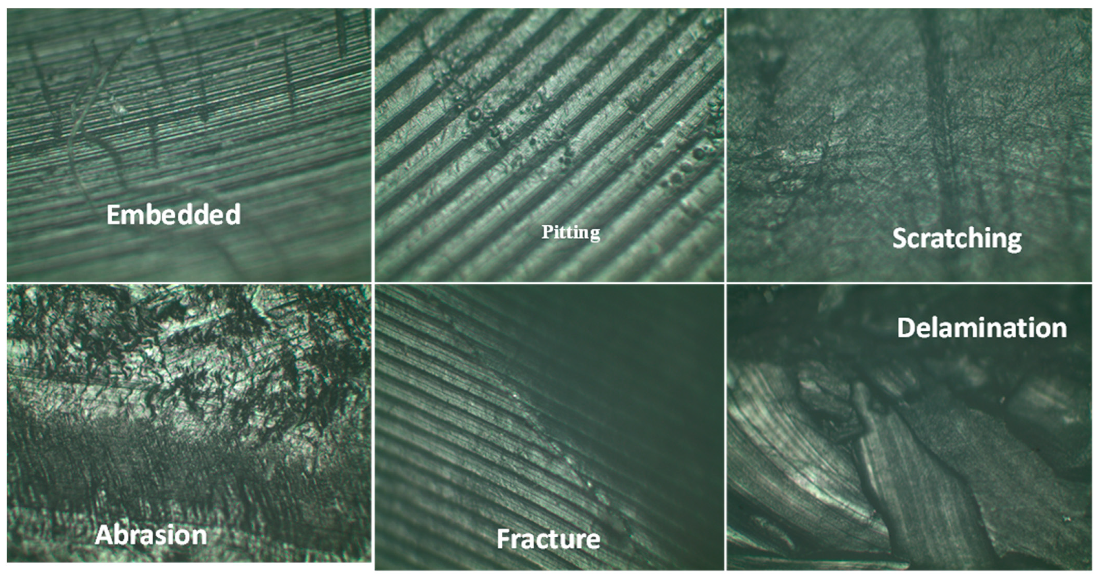
Figure 1.
Examination of liners for various types of wear damage. (a) Delamination of Liner B1B9. (b) Surface Pitting of Liner B2B8. (c) Mixture of Delamination with Surface Abrasion on Liner B1B1. (d) Surface Scratches Seen within the Cup of Liner B1B8. (e) Burnishing of Articulating Surface of Liner B2B1. (f) Deformation Caused by Delamination, Apparent Subluxation, and Cracking. (g) Embedded Debris in Liner B1B6. (h) Complete Fracture of liner B1B9.


Figure 2.
Percentage Occurrence of Particular Wear Modes for Each of the Liners Examined.

Figure 3.
Stereomicroscopy Using a Universal Arm to Hold the Liners.

Figure 4.
Stereomicroscopy Using a Universal Arm to Hold the Liners shows different damage features on different glenoid liners documented in Figure 1.
Figure 4.
Stereomicroscopy Using a Universal Arm to Hold the Liners shows different damage features on different glenoid liners documented in Figure 1.

Figure 5.
Stereomicrograph of damage features observed in the glenoid liners. (a) Machining Marks Surrounding the Formation of Groove with Scratching on the Perimeter. (b) Grooves Forming an Abrasion on Liner B2B3. (c) Example of damaged and B2B11 (left) and undamaged Humeral Head B2B8 (right). (d) Liner B1B9 showing pitting and baseline sur-face deformity.

Figure 6.
Results from Microscopic Inspection.

Figure 7.
Pitting and delamination of liner B1B5, embedded debris, and UHMWPE particles in B1B8.

Figure 8.
Pitting and Embedded Debris on Liner B2B8.

Figure 9.
FTIR Apparatus Used in Attempted to Characterize Oxidation.

Figure 10.
Graph Representing Fraction of Failed Liners Versus Time as a Cumulative Distribution and Mean Liner Life.
Figure 10.
Graph Representing Fraction of Failed Liners Versus Time as a Cumulative Distribution and Mean Liner Life.

Figure 11.
The Rate of Failure Shown as a Probability Density Function.

Figure 12.
The survival function of Liners as a Complimentary Cumulative Probability Distribution Constrained by a 95% Confidence Interval showing mean, upper and lower bound trends.
Figure 12.
The survival function of Liners as a Complimentary Cumulative Probability Distribution Constrained by a 95% Confidence Interval showing mean, upper and lower bound trends.


Table 1.
Parts List of Total Contents Examined.
| Part Number | Replacement Type | Components Included |
|---|---|---|
| B1B1 | Reverse | UHMWPE Liner |
| B1B2 | Traditional | UHMWPE Liner |
| B1B3 | Traditional | Intramedullary Rod, Humeral Ball, UHMWPE liner, Fixation Screw |
| B1B4 | Reverse | Intramedullary Rod, Humeral Head, Liner Cup, UHMWPE Liner, Glenoid Base Plate, 4 Fixation Screws |
| B1B5 | Reverse | UHMWPE Liner |
| B1B6 | Reverse | Intramedullary Rod, UHMWPE Liner, 4 Fixation Screws, Glenoid Base Plate, Ball |
| B1B7 | Reverse | Intramedullary Rod, UHMWPE Liner, Liner Cup, 3 Fixation Screws, Glenoid Baseplate |
| B1B8 | Reverse | UHMWPE Liner |
| B1B9 | Traditional | UHMWPE Liner |
| B1B10 | Reverse | UHMWPE Liner |
| B1B11 | Reverse | UHMWPE Liner |
| B1B12 | Traditional | UHMWPE Liner |
| B2B1 | Traditional | UHMWPE Liner |
| B2B2 | Traditional | UHMWPE Liner |
| B2B3 | Traditional | UHMWPE Liner |
| B2B4 | Reverse | UHMWPE Liner |
| B2B5 | Reverse | UHMWPE Liner |
| B2B6 | Traditional | UHMWPE Liner |
| B2B8 | Traditional | UHMWPE Liner, Ball |
| B2B10 | Traditional | UHMWPE Liner, Glenoid Baseplate, Humeral Shaft, Ball |
| B2B11 | Reverse | Humeral Shaft, UHMWPE Liner, Liner Cup, Ball, Glenoid Baseplate, 4 Screws |
| B2B12 | Traditional | Humeral Shaft, Humeral Head Attached, UHMWPE liner |
| B2B14 | Traditional | Humeral Shaft, Humeral Head, UHMWPE Liner |
Table 2.
Hardness Results Measured in Shore D for Both Sets of Liners Examined.
| Box 1 | Hardness | Box 2 | Hardness |
|---|---|---|---|
| B1B1 | 70.9 | B2B1 | 65.2 |
| B1B2 | 69.0 | B2B2 | 71.0 |
| B1B3 | 66.2 | B2B3 | 57.3 |
| B1B4 | 78.4 | B2B4 | 74.0 |
| B1B5 | 68.1 | B2B5 | 66.6 |
| B1B6 | 71.3 | B2B6 | 66.0 |
| B1B7 | 73.7 | B2B7 | 65.7 |
| B1B8 | 83.8 | B2B8 | 74.3 |
| B1B9 | 69.2 | B2B9 | 74.3 |
| B1B10 | 68.9 | B2B10 | 59.6 |
| B1B11 | 74.7 | B2B11 | 75.9 |
| B1B12 | 69.6 |
Table 3.
Total Average Hardness with Sample Population Standard Deviation.
| Total Average Hardness Shore D | Standard Deviation | |
|---|---|---|
| Traditional | 67.4 | 6.0 |
| Reverse | 73.1 | 6.1 |
Table 4.
Availability of the Liners as a Ratio of Expected Operable Use Versus Actual Useable Time.
| Measure | Confidence Bounds | ||
|---|---|---|---|
| 5% | Mean | 95% | |
| Operational Availability | 0.504 | 0.533 | 0.563 |
| Inherent Availability | 0.504 | 0.533 | 0.563 |
Publisher’s Note: MDPI stays neutral with regard to jurisdictional claims in published maps and institutional affiliations. |
© 2022 by the authors. Licensee MDPI, Basel, Switzerland. This article is an open access article distributed under the terms and conditions of the Creative Commons Attribution (CC BY) license (https://creativecommons.org/licenses/by/4.0/).
Share and Cite
MDPI and ACS Style
Cheatwood, E.; Simon, G.; Crosby, L.; Goswami, T. Characterization of In Vivo Damage on Retrieved Total Shoulder Glenoid Liners. Lubricants 2022, 10, 166. https://0-doi-org.brum.beds.ac.uk/10.3390/lubricants10080166
AMA Style
Cheatwood E, Simon G, Crosby L, Goswami T. Characterization of In Vivo Damage on Retrieved Total Shoulder Glenoid Liners. Lubricants. 2022; 10(8):166. https://0-doi-org.brum.beds.ac.uk/10.3390/lubricants10080166
Chicago/Turabian StyleCheatwood, Eric, Gerard Simon, Lynn Crosby, and Tarun Goswami. 2022. "Characterization of In Vivo Damage on Retrieved Total Shoulder Glenoid Liners" Lubricants 10, no. 8: 166. https://0-doi-org.brum.beds.ac.uk/10.3390/lubricants10080166
Note that from the first issue of 2016, this journal uses article numbers instead of page numbers. See further details here.