Influence of Active Cooling at the Trailing Edge on the Thermal Behavior of a Tilting-Pad Journal Bearing


Product Development, Ruhr-University Bochum, 44801 Bochum, Germany
*
Author to whom correspondence should be addressed.
Lubricants 2021, 9(3), 26; https://0-doi-org.brum.beds.ac.uk/10.3390/lubricants9030026
Submission received: 31 January 2021
/
Revised: 19 February 2021
/
Accepted: 22 February 2021
/
Published: 2 March 2021
(This article belongs to the Special Issue Advances in Lubricated Bearings)
Abstract
:In tilting-pad journal bearings (TPJB) with a non-flooded lubrication concept, higher maximum pad temperatures occur than with a flooded bearing design due to the lower convective heat transfer at the pad edges. In this paper, we present an approach to influence the thermal behavior of a five-pad TPJB by active cooling. The aim of this research is to investigate the influence of additional oil supply grooves at the trailing edge of the two loaded pads on the maximum pad temperature of a large TPJB in non-flooded design. We carry out experimental and numerical investigations for a redesigned test bearing. Within the experimental analysis, the reduction in pad temperature is quantified. A simulation model of the bearing is synthesized with respect to the additional oil supply grooves. The simulation results are compared with the experimental data to derive heat transfer coefficients for the pad surfaces. The experimental results indicate a considerable reduction of the maximum pad temperatures. An overall lower temperature level is observed for the rear pad in circumferential direction (pad 4). The authors attribute this effect by a cooling oil carry-over from the previous pad (3). Within the model limits, a good agreement of the simulation and experimental results can be found.
1. Introduction
In turbomachinery, hydrodynamic bearings are mainly applied to support rotor shafts. Due to the continuous development of fast running turbomachinery, the requirements for the bearings with regard to load carrying capacity, operational safety and efficiency also increase. To ensure safe operation, wear due to mixed friction is prevented, the permissible maximum temperature is not exceeded and mechanical overstressing of the materials is avoided. In addition, an economic aim is to achieve the lowest possible power loss of the bearings.
The power loss of a bearing corresponds to the power converted into heat due to friction. This friction is caused by shearing of the oil in the lubrication gap and is inevitably linked to the hydrodynamic principle. However, friction does not only occur in the lubricating gap between the shaft and the running surface, where the bearing’s load capacity is generated. Also in the areas that do not contribute to the bearing’s load carrying capacity, a notable proportion of frictional power arises. In tilting-pad journal bearings (TPJB), the power loss occurs mainly in the intermediate spaces between two consecutive pads. The frictional power in these areas can, depending on the oil-air mixture, amount up to 50% of the total power loss of the bearing.
Basically, there are two lubrication concepts for TPJB: flooded and non-flooded design. With a flooded lubrication concept, the intermediate spaces between the pads are fully filled with oil. In a non-flooded bearing design, there is theoretically no oil in the intermediate space and therefore less friction compared to the flooded design. While power loss can be reduced considerably with a non-flooded lubrication concept, maximum temperatures at the pads trailing edge increase. In a flooded bearing design, high flow velocities and the mixing of fresh and draining oil effect a high convective heat transfer at the leading and trailing edge of the pads. The convective heat transfer at the trailing edge is assumed to have a major influence on the maximum pad temperature, as the intermediate spaces in a non-flooded bearing are almost oil-free. Therefore, the temperature rise with a non-flooded lubrication concept is due to the lower convective heat transfer at the pads edges.
Improving the heat transfer at the trailing edge seems to be a reasonable approach to reduce maximum pad temperatures in non-flooded bearing design. In practice, suitable design changes have to be applied to the corresponding bearings. In this context, we investigate the following research question: How does active cooling at the trailing edge influence the thermal behavior of a large TPJB?
1.1. State of the Art
1.1.1. Bearing Calculation Models
Theoretical models are developed for a better understanding of the physical processes in hydrodynamic bearings. Validating these models with experimental data increases model complexity and enables phenomena such as heat transfer to be considered. For the development of hydrodynamic bearings, such models are vital in order to make accurate predictions of the bearing performance. Currently, there are several theoretical approaches to the calculation of hydrodynamic bearings.
The investigations of Mittwollen [1], Gerdes et al. [2] and Fuchs [3] form the basis for the calculation tool Allgeimes LagerProgramm mit 3-dimensionalem Temperatureinfluss, English: General Bearing Program with 3-dimensional Temperature Influence (ALP3T). Waltermann [4] determines bearing characteristics considering two-dimensional deformation of the running surface. The journal bearing calculation tool COMputation of Bearings for ROtor Systems (COMBROS-R) represents the current state of the art and offers a wide range of calculation and functions with regard to static and dynamic bearing characteristics, bearing geometry and model depth [5,6,7]. Simulation results of both tools, ALP3T and COMBROS-R, show good agreement with experimental data [7,8].
According to the current state of the art, the oil flow in the bearing is not modeled except for the lubrication gap. Thus, in TPJB oil flow in oil supply grooves and the intermediate space between the pads is not taken into account. A consideration of coupled heat flows at the interfaces of the individual regions (bearing ring-lubricating film-shaft) is therefore not possible. To describe the heat dissipation at the interfaces of the bearing, heat transfer coefficients (HTC) are required at the free pad surfaces (leading edge, trailing edge, axial edges, pads back) or the outer system boundaries.
1.1.2. Heat Transfer in Thrust Bearings
Various approaches to determine convective HTC theoretically or experimentally can be found in literature. Most of these publications focus on thrust bearings. Ettles et al. [9] develop a method to model heat transfer at the free pad surfaces considering rotational speed, oil viscosity and pad length. The calculation for this method is derived from temperature measurement data of seven different thrust bearings. Based on the empiric approach of Ettles et al. [9] Ettles [10] investigates a large tilting-pad thrust bearing. Heinrichson et al. [11] also use the calculation method proposed by Ettles et al. [9] to determine the HTC at the free pad surfaces and pads back of a thrust bearing. Heinrichson et al. [12] contrast the calculation results with experimental data and obtain a good agreement between simulation and measurement.
A detailed overview of the published HTCs of different authors with regard to thrust bearings is given by Wodtke et al. [13]. A total of 15 different bearings of different diameters (including the bearings investigated by Ettles et al. [9]) are considered. The outer diameters of the bearings vary between 149 mm and 3100 mm. The HTC of all pad surfaces used are between 100 W/(m2 K) and 3000 W/(m2 K). Some authors additionally describe the convective coefficients as a function of the rotational speed in order to model an influence of the flow change in the pads intermediate spaces. Wodtke et al. [13] compare two different approaches to describe the heat transfer in their study. On the one hand, a constant heat transfer at all surfaces of 750 W/(m2 K) is assumed and, on the other hand, a HTC determined with the help of computational fluid dynamics (CFD) analysis is considered. The validation based on experimental data shows a considerable improvement of the theoretical results with the variable, but lower HTC.
Papadopoulos et al. [14] define HTC between 20 W/(m2 K) and 1000 W/(m2 K) when studying a thrust bearing. The ambient temperature is assumed to be equal to the feed temperature of 40 C. A comparison to experimental data is not given.
1.1.3. Heat Transfer in Journal Bearings
Taniguchi et al. [15] present an approach to calculate the bearing properties of a TPJB, also taking into account the heat conduction through the pads. For the HTC they assume 115 W/(m2 K) up to 350 W/(m2 K) and set a calculated mixing temperature as the ambient temperature. The calculation results show good agreement with the experimental data of a ⌀-479 mm bearing. Within the FVA project no. 577 Improved Journal Bearing Calculation Hagemann [5] examines a ⌀-500 mm five-pad TPJB for validation of COMBROS-R. A HTC of 250 W/(m2 K) is assumed at all free pad surfaces with an ambient temperature of 50 C. The calculation procedure and the results are also discussed in the publications of Hagemann et al. [16] and Kukla et al. [17] and show good agreement between calculation results and experimental data. Kukla et al. [18] apply an optimization procedure to the same ⌀-500 mm five-pad TPJB already used by Hagemann [5]. They determine the HTC at the free pad surfaces by minimizing the deviations between measured and calculated measuring point temperatures. Depending on the pad surface, the HTC are in a range of 490 W/(m2 K) up to 2664 W/(m2 K). The experimentally measured oil drain temperature is used as the ambient temperature.
Sano et al. [19] investigate a ⌀-890 mm two-pad TPJB. Based on CFD analyses, which are not described in detail, a range of HTC of 100 W/(m2 K) up to 1000 W/(m2 K) is given depending on the operating conditions of the bearing. The ambient temperature is set approximately equal to the oil drain temperature.
Hagemann et al. [20] examine both theoretically and experimentally different methods of oil feed of a ⌀-120 mm test bearing. With the help of CFD investigations, HTC at the leading and trailing edge are derived and classified on the basis of experimentally recorded data. Depending on the feed, the values range between 250 W/(m2 K) and 1000 W/(m2 K) for the leading edge and 1000 W/(m2 K) and 1900 W/(m2 K) for the trailing edge with an assumed ambient temperature of 50 C. Arihara et al. [21] observe a ⌀-101.6 mm four-pad TPJB at an ambient temperature of 40 C. Due to turbulent flow and oil mixing in the pads intermediate spaces, a notably higher HTC of 1750 W/(m2 K) is assumed at the leading and trailing edge than of 500 W/(m2 K) for the axial edges. Similar values are given by Hagemann et al. [22] for a high-speed four-pad TPJB with a diameter of 120 mm. The HTC determined by CFD analyses are in a range of 1500 W/(m2 K) up to 1900 W/(m2 K) at the trailing edge and at the leading edge between 300 W/(m2 K) and 400 W/(m2 K).
1.1.4. Design Changes for Improvement of Bearing Characteristics
The variety of different HTC indicates insufficient knowledge of the phenomena and the associated heat transfer in the intermediate spaces between the pads. All publications mentioned are concerned with a better prediction or description of the heat transfer without aiming to influence the heat transfer by design modification on a theoretical level. However, several researchers carry out design changes to improve the bearing characteristics of various journal bearings.
Chen et al. [23] and Chen et al. [24] develop an isothermal circular-cylindrical journal bearing, which is equipped with methanol-filled heat transfer chambers below the running surface in the bearing ring. In the thermally loaded areas of the bearing, the methanol evaporates, transports the heat away and heats the unloaded areas of the bearing. Compared to a conventional bearing, the isothermal bearing has notably lower operating temperatures, as the test data prove. Experimental investigations by Nicholas [25] show that so-called spraybar blockers in combination with bypass cooling have a positive effect on the thermal behavior of the bearing. The spraybar blockers are a kind of scraper edge that reduces the excess hot oil. By means of bypass cooling, fresh oil is fed directly to the pads back, which is designed with cooling grooves. Martsinkovsky et al. [26] arrange oil wipers between the pads in a three-pad TPJB to minimize the effect of hot oil carry-over. In addition, several cooling channels in axial direction are manufactured at the trailing edge below the surface. The authors report a temperature reduction compared to the bearing design without the channels.
Mermertas et al. [27] and Mermertas et al. [28] publish an improved design of a ⌀-900 mm TPJB that previously exhibited high bearing temperatures and a noticeable feed temperature dependence during operation. Based on extensive thermomechanical analyses, the support position, pad dimensions and oil feed are modified. With these modifications, the bearing shows a more robust and reproducible characteristic. Hermes [29] presents a strong chamfering of the pads trailing edge to improve the operating characteristics. Compared to the initial situation, the bearing can be operated at considerably reduced temperatures with the same load capacity.
Kukla [30] improves the steady-state operating characteristics of a ⌀-500 mm five-pad TPJB by means of an axially concave profiling of the running surface. The profiling ensures that the running surface deformations occurring under high thermal loads can be almost completely compensated. Compared to the characteristic values of the critical operating point of the non-profiled initial form, the profiled bearing can be operated at the same operating point with a notably reduced temperature and increased oil film thickness. Kukla et al. [31] and Buchhorn et al. [32] present two theoretical approaches to influence and improve the steady-state operating characteristics of a ⌀-500 mm TPJB without experimental validation. Both approaches focus on a single pad in their simulation model, which considers additional volume flows through the pad into or out of the lubrication gap. Kukla et al. [31] use the oil film pressure at the trailing edge to transfer the heated oil to the pads back. Due to the heating and the more homogeneous temperature distribution, the thermomechanical deformations can be reduced. Buchhorn et al. [32] inject a small volume flow of cold oil into the lubrication gap. The additional cold oil volume flow effects a kind of flushing away of the warm oil from the running surface and therefore reduces the maximum oil film temperatures and the pad deformation.
Most design changes aim at improving the bearing characteristics by geometrical variations of the bearing parameter. Only Nicholas [25] investigates enhanced heat transfer for free pad surfaces. A design modification to improve heat transfer at the trailing edge of a pad is currently not known.
1.2. Scope and Aims
In this paper, we present an approach to influence the thermal behavior of a five-pad TPJB by active cooling. The cooling is realized by adding oil supply grooves at the trailing edge of the two highly loaded pads. The aim of this research is to investigate the influence of these additional oil supply grooves on the maximum pad temperature of a large TPJB in non-flooded design. We carry out experimental and numerical investigations for the redesigned test bearing from Kukla’s studies [30]. Within the experimental analysis, the reduction of pad temperature is quantified. A simulation model of the bearing is synthesized with respect to the additional oil supply grooves. We compare the simulation results with the experimental data to derive HTC for the pad surfaces. With these coefficients, the simulation model allows us to make better predictions for the operating characteristics of large TPJB.
2. Experimental Set-Up
2.1. Test Rig
The experiments for this paper are carried out on a test rig for large journal bearings. The test rig was designed in the 1980s to examine original sized turbine bearings under practical operating conditions. The nominal bearing diameter is 500 mm with a maximum length of 500 mm. By means of a 1.2 MW DC drive (Brown, Boveri & Cie. (BBC)), the shaft can be run up to a rotational speed of 4000 rpm depending on friction loss. Thus, circumferential velocities up to 104.7 m/s can be achieved. The lubricant used is turbine oil ISO VG 32 (Esso Teresso 32, Hamburg, Germany). Figure 1 shows the top view of the test rig and a technical drawing.
In the test rig, the shaft (2) is supported by two symmetrically aligned support bearings, which are designed as tilting-pad bearings with three pads (3). The test bearing (1) is attached to a rigid frame (9) centrally between the support bearings. The rigid frame is connected to a pneumatic bellow (6) via two drawbars (8) and a traverse (7). The pneumatic bellow is mounted on the upper part of the test rig frame (5). This upper part and the two support bearings are supported by the lower part of the test rig frame (4). By pressurizing the bellow, the bearing is pulled against the shaft from below. A maximum bearing force of 1 MN can be applied.
The shaft, designed as a hollow shaft, is equipped with to capacitive distance sensors and two piezoelectric pressure sensors. The sensors are arranged in the mid plane of the shaft with a circumferential distance of 90° to each other. Sensors of the same type are 180° apart. The sensor plane can be moved across the whole test bearing width by axially shifting the rotating shaft during measurement. Thus, both the fluid film thickness and pressure distribution can be measured in a high-resolution two-dimensional (2D) data field. In circumferential direction 240 data values are captured. Depending on the rotational speed, up to 4000 data values can be recorded in axial direction. Due to the use of capacitive distance sensors, the film thickness can only be measured reliably in areas where the gap is completely filled with oil. However, areas of cavitation and deficient lubrication can be detected by this characteristic.
In addition to stationary force, the test bearing can be loaded by sinusoidal dynamic forces. Two vibration generators (10) are attached to the rigid frame at 90° to each other and each at 45° to the stationary force in vertical direction. To determine the dynamic coefficients of the test bearing, relative movement between shaft and test bearing is measured by four eddy current distance sensors. Kukla et al. [17] give a detailed description of the vibration generators, the measurement system and post-processing.
2.2. Test Bearing
The test bearing is a five-pad TPJB in a load between pad configuration. The nominal bearing diameter is 500 mm. Both, the pads back and bearing ring are manufactured with a radius in axial direction leading to an elliptical pivot geometry. This pivot geometry enables a double-tilt support of the pads, hence a tilting in both axial and circumferential direction to better compensate for misalignment between shaft and bearing. The two lower, highly loaded pads each feature hydrostatic jacking grooves on the running surface above the pivot area. In both pads, the running surface is manufactured with an axial concave profile following Kukla [30] to compensate for thermal crowning at high specific loads. Table 1 shows the bearing key parameter.
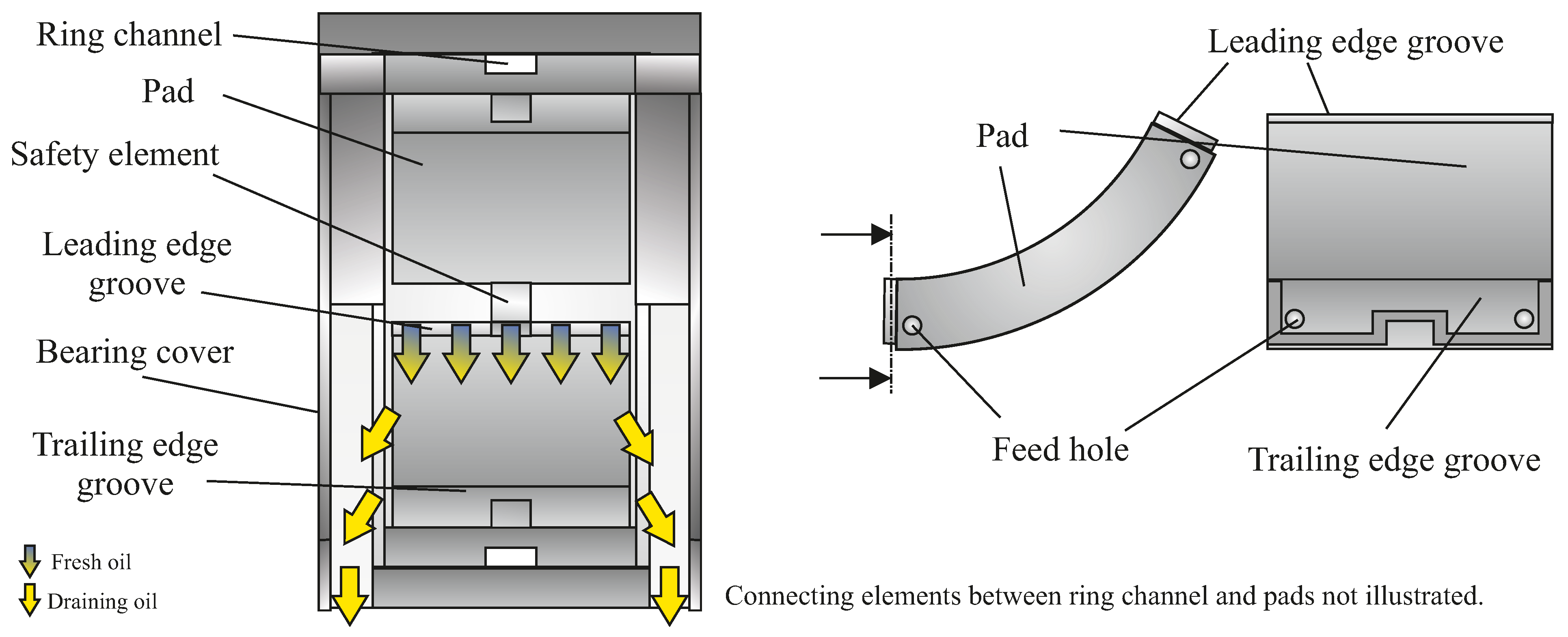
Oil is supplied via a ’leading edge groove’ (LEG) mounted directly on the pads leading edge (Figure 2). This directed lubrication allows a non-flooded lubrication concept for the bearing to reduce friction loss. Therefore, no axial seals are inserted and the intermediate space between the pads is enlarged in radial direction. Additionally, the bearing is designed with oil drain channels and large spacing between pads and axial bearing covers to avoid oil accumulation in the bearing except for the lubrication gap. The two lower pads are each equipped with additional ‘trailing edge grooves’ (TEG) for active cooling of the trailing edge. A safety mechanism mounted in the pivot area to keep the pads in place hinders the oil feed through the pivot. Hence, oil is fed in via the pads axial edges (Figure 2 and Figure 3). Both supply grooves, LEG and TEG are supplied separately via several internal galleries between bearing ring and housing (Figure 3).
3. Experimental Results and Discussion
The experimental results in hydrodynamic operation are presented below. Tests were carried out under purely stationary operating conditions. The main oil supply for the bearing was L/s at a feed temperature of 50 °C at all operating points. The results are compared in each case without and with feeding of the additional groove at the end of the two loaded pads. The following total cooling volume flows are examined:
- L/s ( L/s per TEG)
- L/s ( L/s per TEG)
- L/s ( L/s per TEG)
- L/s ( L/s per TEG)
The temperature of the cooling oil supplied is also 50 C. It is assumed that the volume flow is divided equally between both grooves at the pad ends.
The comparison to a bearing without cooling is aimed to investigate the direct effect of an additional groove at the end of thermally highly loaded pads. This is given if the additional grooves are not supplied.
The axial concave profiling has been determined by Kukla [30] for a specific bearing load of MPa. However, the experimental investigations show that a residual profiling remains under the thermal conditions that arise at this bearing load. This axially concave residual profiling decreases with increasing load. Therefore, for the following consideration of the experimental data of the test bearing, an operating point at a speed of 3000 rpm and a specific bearing load of 3.00 MPa is selected.
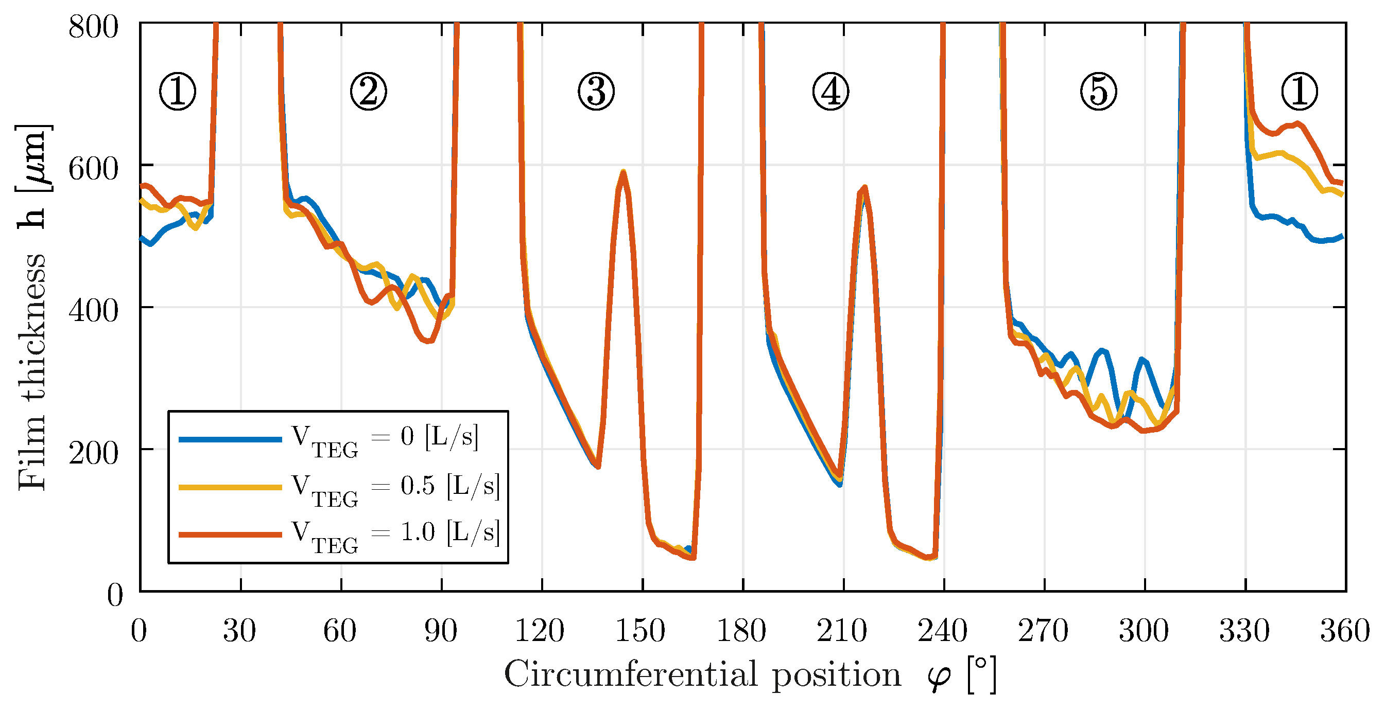
The graphs of the oil film thickness measured in the center of the bearing at a specific bearing load of 3.00 MPa and a speed of 3000 rpm are shown in Figure 4 without and with additional cooling.
A comparison of the three curves shows that the experimentally recorded oil film thicknesses differ only slightly. The gaps of the two loaded pads 3 and 4 are completely filled, while those of the unloaded pads 1, 2 and 5 do not show complete filling—recognisable from the non-steady course of the measured values. An influence of the additional cooling on the radial pad deformation in the area of the pad ends (pad 3: approx. 172°; pad 4: approx. 238°) cannot be determined from the measurement data. No influence on the axial deformations could be detected during the tests either.
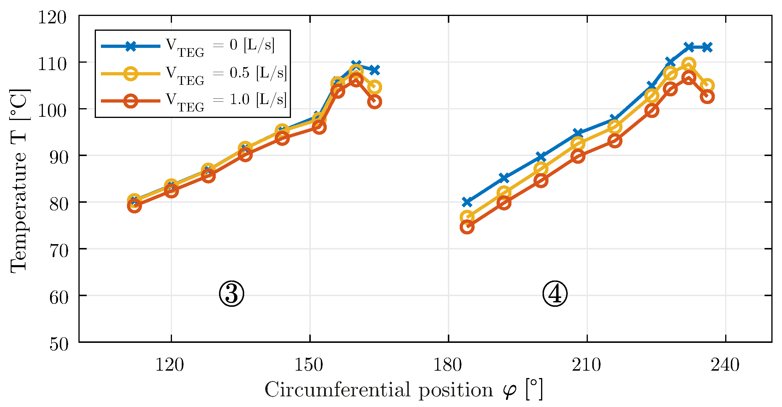
The effect of the additional trailing edge cooling becomes obvious (Figure 5), if the curves of the temperatures in the center of the bearing for the loaded pads 3 and 4 are considered: While only the temperature level at the end of the pad is influenced for pad 3, the entire temperature level is reduced for pad 4.
The influence on the thermal behavior of pad 4 is due to a cooling oil carry-over. The effect is caused by the additional feeding at the trailing edge of pad 3. In addition to the hot oil leaving the end of pad 3, a portion of the supplied cooling oil is carried over to the beginning of pad 4. This provides a larger amount of fresh oil to the pad. The increased volume flow and the reduced gap inlet temperature result in a lower overall temperature level. Nevertheless, the qualitative temperature curves of pad 3 and 4 are similar for the two cases considered with additional cooling. The effect of trailing edge cooling can only be seen in isolation for pad 3 due to the mixing of the effects described for pad 4. The improved heat dissipation at the end of the pad can reduce the maximum temperature and the temperatures at the trailing edge.
In general, the additional supply to the low-pressure TEG provides the bearing with a larger quantity of lubricant, even if this is concentrated on the respective rear edges of the loaded pads (see Figure 6). A larger volume flow inevitably leads to an improvement in certain properties, with first and foremost the maximum temperature that is achieved. In order to be able to estimate the influence of a higher total volume flow rate on the thermal properties, the experimentally determined maximum bearing temperatures (left) and the corresponding power loss (right) are plotted versus the total oil flow rate in Figure 7. For this purpose, the same total volume flow is supplied to the bearing via the leading edge grooves as in the tests at a nominal oil flow ( L/s) with additional cooling via the TEG at pads 3 and 4.
As expected, a higher oil flow rate has a positive effect on the maximum temperature of the bearing. The measured maximum pad temperatures are on average 5 K above those with additional cooling of the trailing edges of the pads. It can be shown that the improvement of the thermal condition is due to the selective feeding at the trailing edges of the highly loaded pads and not to the increased oil flow rate. When the nominal flow rate is increased, all pads benefit from the increased flow rate. The thermal properties of individual pads improve specifically, mainly those of the two lower thermally highly loaded pads, if the additional cooling grooves are fed. The measured power losses of the two variants show qualitatively corresponding curves, whereby that of the bearing with trailing edge cooling is slightly higher. However, this is plausible due to the additional shear stresses occurring in the two TEG at the pads 3 and 4.
4. Numerical Procedure
With the model, we introduce an approach to simulate the influence of the additional TEG on the thermal pad characteristics. In the further course, the model is used for the theoretical investigations and the simulation results are compared with the test data. The modeling can be subdivided as follows:
- CFD calculation of a single pad with additional supply groove at the end of the pad (OpenFOAM)
- Thermohydrodynamic journal bearing calculation considering thermomechanical pad deformations (COMBROS-CalculiX)
CFD analyses are used to determine the dissipated heat flows at the end of a pad. The open source software package OpenFOAM is used. The coupling of structure (pad) and flow space is done with the CHT (conjugated heat transfer) method, in which equal temperatures and heat flows are assumed at phase boundaries. Thermomechanical pad deformations are not calculated within the CFD, but are taken into account by specifying the flow space based on the measured data.
For the determination of the steady-state operating characteristics, a coupling of the journal bearing calculation tool COMBROS with the open source finite element (FE) tool CalculiX based on the work of Kukla [30] is modified and used.
4.1. CFD Calculation with OpenFOAM
The chtMultiRegionSimpleFoam solver of the simulation software package OpenFOAM-4.x (Open Source Field Operation and Manipulation) is used as CFD solver running within the Windows porting blueCFD-Core 2016-2. The solver calculates a stationary, turbulent, incompressible flow with the finite volume method. Flow, pressure and temperature fields, the heat exchange between fluid and solid and the temperature distribution in the solid are determined. Only single-phase flow is considered. Cavitation areas are not considered. Turbulence influences are modeled with the k--SST model.
A consideration of the dissipative term is indispensable for the correct determination of the heat entry into the pad or the heat generation in the gap flow. Therefore the energy equation of the solver (Equation (1)) is extended by the dissipative term taking into account the shear forces according to Equation (2) to determine the temperature.
Included in the equation are the specific heat capacity c, density , velocity components , thermal conductivity , viscosity and temperature gradients . For the temperature-dependent dynamic viscosity, the relation given by Falz [33,34] is implemented as a function of a reference temperature T0, a reference viscosity and the Falz exponent I, which is a specific property of the respective ISO-VG (International Organization for Standardization Viscosity Grade) class (Equation (3)).
Figure 8 shows two exemplary models that are built with a reduced number of nodes for the sake of clarity. The left part of the figure shows a model without an additional groove. The right part of the figure shows an example of a pad model with an additional groove at the end of the pad, the flow space is not shown. The models are designed assuming symmetry to the center of the bearing.
Due to computing times and data capacities, the simulation only considers a single pad without the surrounding spaces. Furthermore, the axial symmetry of the bearing is utilized when creating the model. However, this means that boundary conditions such as the shaft temperature must be specified. The boundary conditions are chosen based on the results of the experimental investigations. In summary, the following boundary conditions are used for the CFD:
- A single pad is considered, without the surrounding space.
- Symmetry to the middle plane of the pad in axial direction.
- Preset of the shaft temperature based on the experimentally collected data.
- Specification of the heat transfer coefficients (literature-based) at pad surfaces that do not belong to the running surface or supply groove.
- Specification of the ambient temperature at pad surfaces that do not count as part of the running surface or supply groove, based on the experimentally recorded data.
- Presetting of the circumferential speed of the shaft based on the shaft speed.
- No-slip condition on the bearing surface.
- No-slip condition on the shaft surface.
- Presetting of the pressure boundary conditions.
- Presetting of the volume flow of the TEG.
- Specification of the supply temperature.
4.2. Thermohydrodynamic Journal Bearing Calculation with COMBROS
For the determination of the steady-state bearing operating characteristics, the state-of-the-art journal bearing calculation program COMBROS version 1.3.0 (Developed at Institute of Tribology and Energy Conversion Machinery, Clausthal University of Technology, Germany) is used. The calculation is based on the simultaneous, iterative solution of the Reynolds and energy equations for the pressure and temperature distribution within the bearing. A comprehensive description of the calculation and function scope can be found in [5,7]. The main features of the program can be characterized as follows:
- Solution of the extended and generalized Reynolds differential equation.
- Simultaneous solution of the 3D energy equation for lubricating film, shaft and pad or bearing.
- Consideration of the occurrence of Taylor vortices and turbulence.
- Consideration of cavitation regions (Elrod algorithm, two-phase model).
- Realistic oil feed model.
- Approximate consideration of thermomechanical tread deformations.
- Interface for coupling of structural mechanics software.
- Consideration of 2D profiling of the running surface.
- Consideration of multi-lobe and tilting-pad bearings.
- Possibility to specify different heat transfer coefficients for different pad surfaces.
Different oil supply systems can be modeled, including direct lubrication via a LEG. The bearing is modeled without additional supply grooves at the end of the pads, as these cannot currently be represented in COMBROS. The TEG are modeled via the heat transfer on the corresponding surfaces of the pads.
The experimental results indicate that the three unloaded pads 1, 2 and 5 show a lack of lubrication at the relevant operating points. No hydrodynamic pressure build-up is generated. According to Hagemann [7], a lack of lubrication leads to instabilities in the numerical calculation of the equilibrium and thus to a negative influence on the convergence behavior. Due to this fact, the tilting mobility of the three pads is blocked in the calculation of the operating properties. There is also no calculation of the thermomechanical deformations of these pads.
4.3. Thermomechanical Deformation Calculation with CalculiX
For the consideration of thermomechanical pad deformations, the structural mechanics tool CalculiXversion 2.17 (Dhondt and Wittig, Germany) is used. The tool is coupled with the journal bearing calculation tool COMBROS. Functionality and scope can be found in the program documentation of Dhondt [35]. The basic coupling of the two programs is based on the procedure described by Kukla [30] with the aid of the development environment Matlab version 2016a (The MathWorks, Inc., Natick, MA, USA).
Based on COMBROS input data, a geometric model of a tilting-pad is built up. The consideration of hydrostatic jacking grooves and a running surface profiling is done by a corresponding offset field, which is imposed on the nodes of the running surface. Required fields such as temperature or deformation data are transferred to the corresponding discretization within Matlab. The following boundary conditions are used for the FE model:
- Blocking of the displacements of the nodes in the contact zone of pad and bearing ring.
- Specification of heat transfer coefficients and side flow temperatures at the pad surfaces.
- Pressure and temperature distribution on the running surface are taken from COMBROS.
4.4. Modeling the Influence of Active Cooling via TEG
The heat flow supplied to or dissipated from a surface A is defined according to Equation (4). In addition to the heat transfer coefficient , this depends notably on the difference between the wall temperature and the temperature of the surrounding fluid .
The heat transfer at pad surfaces is described by the heat transfer coefficients at the respective surfaces and the ambient temperature. As the ambient temperature the mean side flow temperature is assumed for all surfaces except the running surface [36].
In order to model the influence of the active trailing edge cooling within the bearing calculation, the heat transfer coefficient is iteratively adjusted in the FE-coupled calculation until the dissipated heat flows match those of the CFD simulations. Figure 9 shows the flow chart for the adjustment of the heat transfer coefficient. Starting from an initial value of the heat transfer coefficient at the trailing edge, a journal bearing calculation is performed. After running through the calculation loop, the temperature field at the trailing edge of pad 3 as well as the average side flow temperature are read out. The temperature field is additionally averaged. Subsequently, the heat flow dissipated over the surface is determined according to Equation (4). If the dissipated heat flow corresponds to that of the CFD simulation within a tolerance range, the iteration loop is exited. Otherwise, the heat transfer coefficient is modified and another calculation run is performed.
5. Simulation Results and Discussion
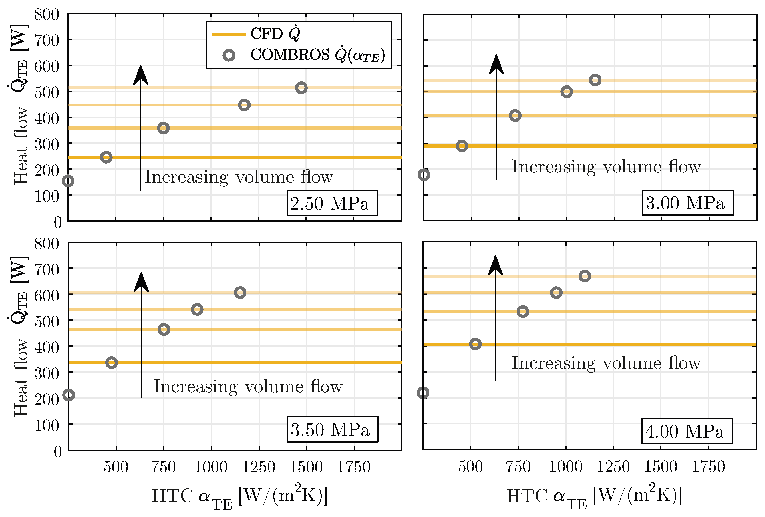
Figure 10 shows the results of the iterative modification of the heat transfer for the specific bearing loads of 2.50 MPa up to 4.00 MPa. The dissipated heat fluxes at the trailing edge of pad 3 resulting from the bearing calculation with COMBROS are plotted against the heat transfer coefficient used. In the diagrams, the heat flows of the CFD simulation are displayed for the various supplied volume flows as reference degrees. In addition, the amount of heat dissipated for a weak heat transfer at a heat transfer coefficient of 250 W/(m2 K) is drawn in each case.
For the considered load cases, all heat flows of the CFD calculations can be mapped with corresponding heat transfer coefficients within the FE-coupled thermohydrodynamic bearing calculation. The heat transfer coefficients are in a range of 450 W/(m2 K) up to 1800 W/(m2 K).
The evaluation of the modeling is done by comparing the simulation results with the experimentally recorded data. The iteratively determined heat transfer coefficients for the different volume flows are used to map the TEG at the pad ends. As an exemplary case, the curves of the oil film thicknesses and measuring point temperatures are considered for a supplied volume flow of L/s. The calculated and measured film thicknesses in the center of the bearing are shown in Figure 11. In the rear area of the loaded pads 3 and 4 behind the hydrostatic jacking grooves, there is a good agreement between the calculated and measured film thicknesses. At the beginning of the gap of the two pads, the curves of the measurement and the calculation differ. Since the tilting mobility of the unloaded pads 1, 2 and 5 is blocked and the pads are not taken into account in the deformation calculation, it is not possible to assess the simulated film thickness on the basis of the measured values.
Figure 12 shows the calculated measuring point temperatures in comparison with the experimental values. Qualitatively, the curves agree well. The calculated temperatures of pad 3 match the experimentally measured values. The calculated temperature at the trailing edge of pad 3 is almost identical to the actual measured temperature. This can also be observed for the maximum measuring point temperature. On the other hand, the temperature curves determined for pad 4 differ more clearly from the measured values. This discrepancy is due to the already described cooling oil carry-over from the TEG of pad 3 to pad 4. This reduces the gap entry temperatures at the beginning of the pad. This effect cannot currently be modeled in COMBROS, which is the reason for the differences in the curves.
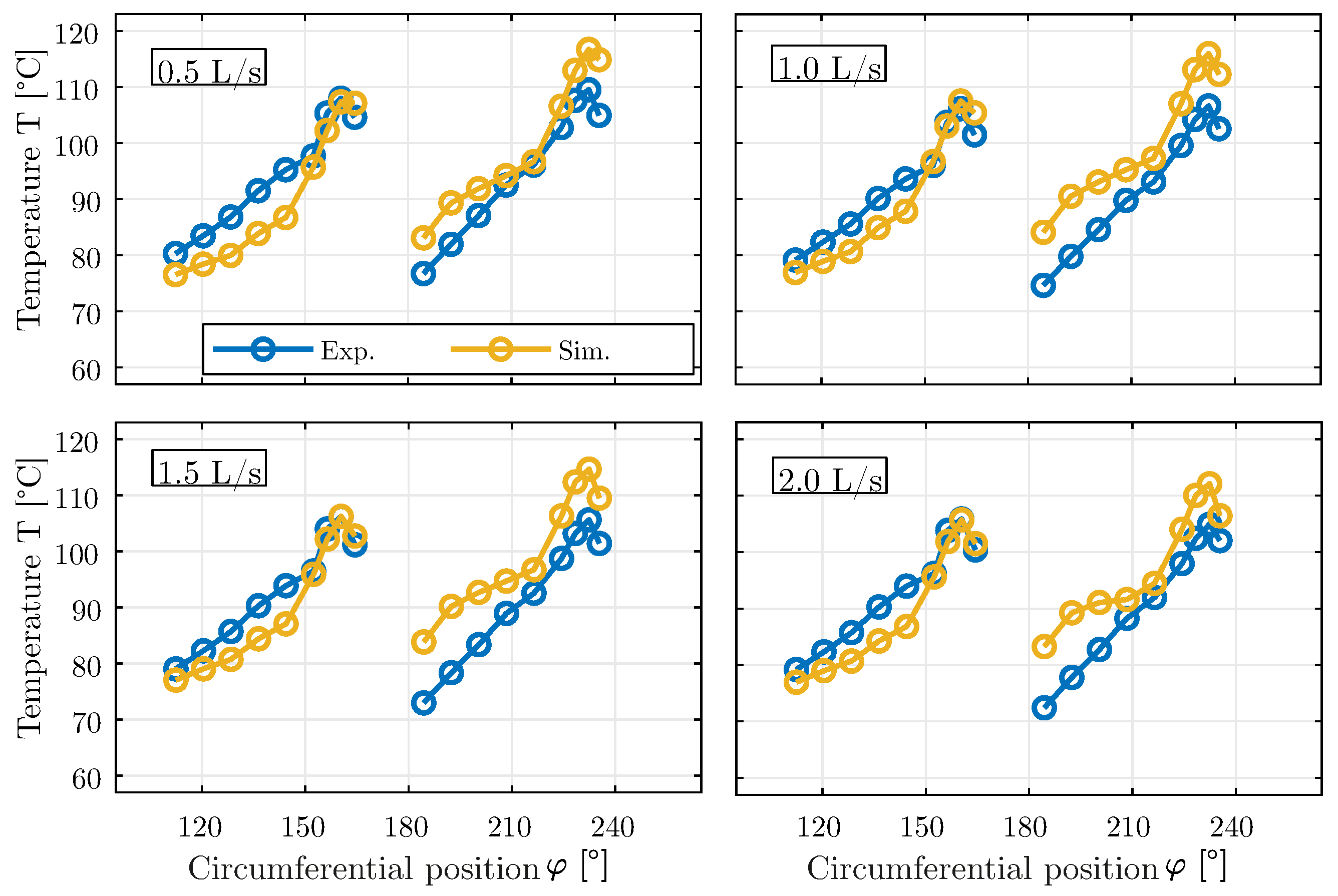
Figure 13 shows the calculated and measured temperature curves of the two loaded pads for different cooling oil volume flows at the trailing edge using the determined heat transfer coefficients in COMBROS.
The pad temperatures at the trailing edge deviate noticeably from the measured values at L/s and L/s. With increasing volume flow, the results agree very well with the measured temperatures. However, the end temperatures are consistently predicted slightly too high. Although the cooling oil carry-over cannot be modeled, the comparison between calculation and measurement results shows that the temperature course at the trailing edge can be qualitatively reproduced. The temperature curve in this area indicates that a similarly large amount of heat is dissipated via the trailing edge of pad 4.
6. Conclusions
The test results show that at high thermal loads, the maximum measuring point temperature of the two loaded pads can be considerably reduced with the help of the additional TEG. A small amount of oil is sufficient (see Figure 5) to influence the temperature of the first loaded pad 3. As the fresh oil flow of the cooling increases, the effect on pad 4 increases. This is mainly due to the extra cooling oil being carried over from the groove at the trailing edge of pad 3 to pad 4. The entire temperature level of pad 4 is thereby lowered. Nevertheless, the improved heat transfer at the trailing edge of pad 4 can be seen by the temperature drop towards the end of the pad.
The measured data indicate a kind of saturation of the heat dissipation with increasing cooling oil volume flow (cf. Figure 6). The benefit of trailing edge cooling must therefore always be considered in relation to the power loss of the bearing. In general, it is possible to influence or specifically improve the thermal behavior of a pad. For example, the maximum temperature can be reduced by up to 3 K at the same load. However, the reduction of the pad temperature at the trailing edge is more notable. This temperature can be reduced by up to 8 K by feeding the TEG. An influence of the additional grooves on the deformation of the pads was not observed.
The use of the procedure to consider the cooling influence provides heat transfer coefficients with which the heat flows determined with the CFD can be adequately transferred to the COMBROS model. The procedure can be used to map the influence of the TEG on the thermal behavior of a pad. However, the procedure is only valid for pad 3. The measurement data show an influence of the additional grooves on the respective downstream pads, which increases with increasing volume flow. As things stand, it is not possible to model the described cooling oil carry-over, so that the temperature curves of pad 4 do not match the experimental data.
In summary, due to the agreement of the simulation and measurement results, the bearing modeling and the representation of the influence of the TEG can be considered valid within the model limits.
Author Contributions
Conceptualization, N.B. and M.S.; methodology, N.B. and B.B.; theoretical investigation, N.B.; experimental investigation, N.B. and M.S.; writing—original draft preparation, N.B. and M.S.; writing—review and editing, N.B., M.S. and B.B.; supervision, B.B.; project administration, N.B.; funding acquisition, N.B. All authors have read and agreed to the published version of the manuscript.
Funding
This research was funded by the German Federal Ministry of Economic Affairs and Energy. The financial support was assigned by the Industrial Research Association (AiF e. V.) in the project “Verbesserte Effizienz großer, schnelllaufender Radialkippsegmentgleitlager für verlustleistungskritische Anwendungen”.
Acknowledgments
We acknowledge support by the Open Access Publication Funds of the Ruhr-Universität Bochum. The authors would like to thank D. Schüler for his valuable advice and GTW Alpen, especially C. Weißbacher, for the support of the experimental investigation and project administration.
Conflicts of Interest
The authors declare no conflict of interest.
Abbreviations
| A | Area |
| B | Bearing length |
| c | Specific heat capacity |
| Radial clearance | |
| D | Nominal diameter |
| h | Film thickness |
| I | FLAZ-exponent |
| Pad preload | |
| n | Rotor speed |
| Specific bearing load | |
| Power loss | |
| Heat flow | |
| r | Radius |
| t | Thickness |
| T | Temperature |
| Flow velocities | |
| V | Volume flow |
| Cartesian coordinates | |
| Heat transfer coefficient | |
| Dynamic viscosity | |
| Thermal conductivity | |
| Density | |
| Angular coordinate | |
| Dissipation | |
| Relative bearing clearance | |
| Rotation speed | |
| Angular pad length | |
| CFD | Computational fluid dynamics |
| FE | Finite elements |
| HTC | Heat transfer coefficient |
| LEG | Leading edge groove |
| TEG | Trailing edge groove |
| TPJB | Tilting-pad journal bearing |
References
- Mittwollen, N. Betriebsverhalten von Radialgleitlagern Bei Hohen Umfangsgeschwindigkeiten und Hohen Thermischen Belastungen—Theoretische Untersuchungen; VDI-Verlag: Dusseldorf, Germany, 1990; Volume 187. [Google Scholar]
- Gerdes, R.; Fuchs, A. Kippsegmentlager-Nachgiebigkeit: Nachgiebigkeit in der Segmentabstützung von Radial-Kippsegmentlagern und Deren Einfluss Auf die Lagerkennwerte und das Schwingungsverhalten Schnelllaufender Rotor-Lager-Systeme; FVA-Heft: Frankfurt, Germany, 1997; Volume 511. [Google Scholar]
- Fuchs, A. Schnelllaufende Radialgleitlagerungen Im Instationären Betrieb. Ph.D. Thesis, TU Braunschweig, Braunschweig, Germany, 2002. [Google Scholar]
- Waltermann, H. Optimierte Thermo-Elasto-Hydrodynamische Berechnungsverfahren für Gleitlager; Reihe Maschinenbau, Shaker: Aachen, Germany, 1992. [Google Scholar]
- Hagemann, T. Verbesserte Radialgleitlagerberechnung: Stationär und Instationär hoch Belastete Radialgleitlager für Schnelllaufende Rotoren Bei Berücksichtigung der Lagerdeformationen; FVA-Heft: Frankfurt, Germany, 2011; Volume 996. [Google Scholar]
- Hagemann, T. Ölzuführungseinfluss bei schnell laufenden, hoch belasteten Radialgleitlagern unter Berücksichtigung des Lagerdeformationsverhaltens. In Fortschrittsberichte des Instituts für Tribologie und Energiewandlungsmaschinen; Shaker: Aachen, Germany, 2012; Volume 17. [Google Scholar]
- Hagemann, T. Dokumentation Radialgleitlagerberechnungsprogramm COMBROS R: Version 1.3.0; ITR, TU Clausthal: Clausthal, Germany, 2017. [Google Scholar]
- Fuchs, A.; Glienicke, J.; Schlums, H. Programmdokumentation zu ALP3T, Version 4.3; FVV Forschungsvorhaben Nr. 662 Robuste Lagerungen: Frankfurt am Main, Germany, 2005. [Google Scholar]
- Ettles, C.M.; Anderson, H.G. Three-Dimensional Thermoelastic Solutions of Thrust Bearings Using Code Marmac1. J. Tribol. 1991, 113, 405. [Google Scholar] [CrossRef]
- Ettles, C.M. The Analysis of Pivoted Pad Journal Bearing Assemblies Considering Thermoelastic Deformation and Heat Transfer Effects. Tribol. Trans. 1992, 35, 156–162. [Google Scholar] [CrossRef]
- Heinrichson, N.; Santos, I.F.; Fuerst, A. The Influence of Injection Pockets on the Performance of Tilting-Pad Thrust Bearings—Part I: Theory. J. Tribol. 2007, 129, 895. [Google Scholar] [CrossRef]
- Heinrichson, N.; Santos, I.F.; Fuerst, A. The Influence of Injection Pockets on the Performance of Tilting-Pad Thrust Bearings—Part II: Comparison Between Theory and Experiment. J. Tribol. 2007, 129, 904. [Google Scholar] [CrossRef]
- Wodtke, M.; Fillon, M.; Schubert, A.; Wasilczuk, M. Study of the Influence of Heat Convection Coefficient on Predicted Performance of a Large Tilting-Pad Thrust Bearing. J. Tribol. 2013, 135, 021702. [Google Scholar] [CrossRef]
- Papadopoulos, C.I.; Kaiktsis, L.; Fillon, M. Computational Fluid Dynamics Thermohydrodynamic Analysis of Three-Dimensional Sector-Pad Thrust Bearings With Rectangular Dimples. J. Tribol. 2014, 136, 011702. [Google Scholar] [CrossRef]
- Taniguchi, S.; Makino, T.; Takeshita, K.; Ichimura, T. A Thermohydrodynamic Analysis of Large Tilting-Pad Journal Bearing in Laminar and Turbulent Flow Regimes With Mixing. J. Tribol. 1990, 112, 542. [Google Scholar] [CrossRef]
- Hagemann, T.; Kukla, S.; Schwarze, H. Measurement and Prediction of the Static Operating Conditions of a Large Turbine Tilting-Pad Bearing Under High Circumferential Speeds and Heavy Loads. In Proceedings of the ASME Turbo Expo 2013: Turbine Technical Conference and Exposition, San Antonio, TX, USA, 3–7 June 2013. [Google Scholar] [CrossRef]
- Kukla, S.; Hagemann, T.; Schwarze, H. Measurement and Prediction of the Dynamic Characteristics of a Large Turbine Tilting-Pad Bearing Under High Circumferential Speeds. In Proceedings of the ASME Turbo Expo 2013: Turbine Technical Conference and Exposition, San Antonio, TX, USA, 3–7 June 2013; p. V07BT30A020. [Google Scholar] [CrossRef]
- Kukla, S.; Buchhorn, N.; Bender, B. Design of an axially concave pad profile for a large turbine tilting-pad bearing. Proc. Inst. Mech. Eng. Part J J. Eng. Tribol. 2017, 231, 479–488. [Google Scholar] [CrossRef]
- Sano, T.; Magoshi, R.; Shinohara, T.; Yoshimine, C.; Nishioka, T.; Tochitani, N.; Sumi, Y. Confirmation of performance and reliability of direct lubricated tilting two pads bearing. Proc. Inst. Mech. Eng. Part J J. Eng. Tribol. 2015, 229, 1011–1021. [Google Scholar] [CrossRef]
- Hagemann, T.; Zeh, C.; Schwarze, H. Heat convection coefficients of a tilting-pad journal bearing with directed lubrication. Tribol. Int. 2019, 136, 114–126. [Google Scholar] [CrossRef]
- Arihara, H.; Kameyama, Y.; Baba, Y.; San Andrés, L. A Thermoelastohydrodynamic Analysis for the Static Performance of High-Speed—Heavy Load Tilting-Pad Journal Bearing Operating in the Turbulent Flow Regime and Comparisons to Test Data. J. Eng. Gas Turbines Power 2019, 141, 021023. [Google Scholar] [CrossRef]
- Hagemann, T.; Schwarze, H. Theoretical and Experimental Analyses of Directly Lubricated Tilting-Pad Journal Bearings with Leading Edge Groove. J. Eng. Gas Turbines Power 2019, 141, 051010. [Google Scholar] [CrossRef]
- Chen, G.; Wang, Q.; Cao, Y.; Tso, C. Development of an Isothermal Journal Bearing Employing Heat-Pipe Cooling Technology. Tribol. Trans. 1999, 42, 401–406. [Google Scholar] [CrossRef]
- Chen, G.; Wang, Q.; Cao, Y. A tribological experimental investigation of a heat-pipe cooled isothermal journal bearing. Tribol. Trans. 2001, 44, 35–40. [Google Scholar] [CrossRef]
- Nicholas, J.C. Tilting Pad Journal Bearings with Spray-Bar Blockers and By-Pass Cooling for High Speed, High Load Applications. In Proceedings of the 32nd Turbomachinery Symposium, College Station, TX, USA, 8–11 September 2003; pp. 9–11. [Google Scholar]
- Martsinkovsky, V.; Yurko, V.; Tarelnik, V.; Filonenko, Y. Designing Radial Sliding Bearing Equipped with Hydrostatically Suspended Pads. Procedia Eng. 2012, 39, 157–167. [Google Scholar] [CrossRef] [Green Version]
- Mermertas, Ü.; Brumbi, F.; Winkler, A.; Böckel, F.; Hagemann, T. Application of an enhanced 900 mm Tilting Pad Bearing in Large Steam Turbines. In Proceedings of the 14th EDF/Pprime Workshop: “Influence of Design and Materials on Journal and Thrust Bearing Performance”, Futuroscope, France, 8–9 September 2015; Volume 2015. [Google Scholar]
- Mermertas, Ü.; Hagemann, T.; Brichart, C. Optimization of a 900 mm Tilting-Pad Journal Bearing in Large Steam Turbines by Advanced Modeling and Validation. J. Eng. Gas Turbines Power 2018, 141, 021033. [Google Scholar] [CrossRef]
- Hermes, G.J. Verbesserung der Betriebssicherheit hydrodynamischer Kippsegment-Radialgleitlager. Tribol. Schmier. 2016, 63, 51–59. [Google Scholar]
- Kukla, S. Erhöhung Der Tragfähigkeit Großer Radialkippsegmentlager Durch Axiale Profilierung Der Segmentlauffläche. Ph.D. Thesis, Ruhr-Universität Bochum, Bochum, Geramny, 2018. [Google Scholar]
- Kukla, S.; Buchhorn, N.; Bender, B. Increase of Operational Safety of Tilting-Pad Journal Bearings by Extraction of Hot Oil at the Trailing Edge. In Proceedings of the ASME 2015 Power Conference Collocated with the ASME 2015 9th International Conference on Energy Sustainability, the ASME 2015 13th International Conference on Fuel Cell Science, Engineering and Technology, and the ASME 2015 Nuclear Forum, San Diego, CA, USA, 28 June–2 July 2015; p. V001T13A007. [Google Scholar] [CrossRef]
- Buchhorn, N.; Kukla, S.; Bender, B. Increased Load Carrying Capacity of Large Tilting-Pad Journal Bearings by Injection of Cold Oil. In Proceedings of the ASME Turbo Expo: Turbine Technical Conference and Exposition, Seoul, Korea, 13–17 June 2016; The American Society of Mechanical Engineers: New York City, NY, USA, 2016; p. V07BT31A026. [Google Scholar] [CrossRef]
- Falz, E. Grundzüge der Schmiertechnik; Springer: Berlin/Heidelberg, Germany, 1931. [Google Scholar]
- Han, D.C. Statische und Dynamische Eigenschaften von Gleitlagern Bei Hohen Umfangsgeschwindigkeiten und Bei Verkantung. Ph.D. Thesis, Universität Karlsruhe, Karlsruhe, Germany, 1979. [Google Scholar]
- Dhondt, G. CalculiX CrunchiX USER’S MANUAL: Version 2.10. 2016. Available online: http://www.dhondt.de/ccx_2.10.pdf (accessed on 1 March 2021).
- Hagemann, T.; Pfeiffer, P.; Si, X.; Zeh, C.; Schwarze, H. Einfluss der Ölzuführung Auf Die Hydraulischen, Energetischen und Mechanischen Vorgänge in Schnell Laufenden und Hoch Belasteten Radialkippsegmentlagern; FVA-Heft: Frankfurt, Germany, 2016; Volume 1184. [Google Scholar]
Figure 1.
Top view and technical drawing of the test rig; Test rig parts: test bearing (1), shaft (2), support bearings (3), lower part of the test rig frame (4), upper part of the test rig frame (5), pneumatic bellow (6), traverse (7), drawbars (8), rigid frame (9), vibration generators (10).
Figure 1.
Top view and technical drawing of the test rig; Test rig parts: test bearing (1), shaft (2), support bearings (3), lower part of the test rig frame (4), upper part of the test rig frame (5), pneumatic bellow (6), traverse (7), drawbars (8), rigid frame (9), vibration generators (10).

Figure 2.
3D-Model of the test bearing and a single pad.

Figure 3.
Principle drawing of the test bearing and a pad with supply grooves.

Figure 4.
Experimentally determined oil film thickness (µm) over the circumference in the bearing center (pads 1–5) with and without feeding of the TEG. Operating point: n = 3000 rpm and = 3.00 MPa.
Figure 4.
Experimentally determined oil film thickness (µm) over the circumference in the bearing center (pads 1–5) with and without feeding of the TEG. Operating point: n = 3000 rpm and = 3.00 MPa.

Figure 5.
Measuring point temperatures (°C) of pads 3 and 4 in the axial center of the bearing (z = 0 mm) with and without feeding of the TEG. Operating point: n = 3000 rpm and = 3.00 MPa.
Figure 5.
Measuring point temperatures (°C) of pads 3 and 4 in the axial center of the bearing (z = 0 mm) with and without feeding of the TEG. Operating point: n = 3000 rpm and = 3.00 MPa.

Figure 6.
Experimentally determined maximum and final temperatures (°C) of pad 3 as well as the power loss depending on the supplied volume flow of the two cooling grooves. Operating point: n = 3000 rpm and = 3.00 MPa.
Figure 6.
Experimentally determined maximum and final temperatures (°C) of pad 3 as well as the power loss depending on the supplied volume flow of the two cooling grooves. Operating point: n = 3000 rpm and = 3.00 MPa.

Figure 7.
Experimentally determined maximum measuring point temperature and friction power as a function of the total volume flow supplied. Operating point: n = 3000 rpm and = 3 MPa.
Figure 7.
Experimentally determined maximum measuring point temperature and friction power as a function of the total volume flow supplied. Operating point: n = 3000 rpm and = 3 MPa.

Figure 8.
Illustration of the CFD model with reduced number of nodes. Left: Tilting-pad (grey) and fluid mesh (yellow) without additional supply groove. Right: Tilting-pad (grey) with TEG (fluid mesh not shown).
Figure 8.
Illustration of the CFD model with reduced number of nodes. Left: Tilting-pad (grey) and fluid mesh (yellow) without additional supply groove. Right: Tilting-pad (grey) with TEG (fluid mesh not shown).

Figure 9.
Flow chart for modifying the heat transfer coefficient at the trailing edge of pad 3.

Figure 10.
Calculated heat flow (W) at the trailing edge of pad 3 as a function of the heat transfer coefficient (W/(m2 K) at different specific bearing loads for the volume flows L/s, L/s, L/s, and L/s. Speed: n = 3000 rpm.
Figure 10.
Calculated heat flow (W) at the trailing edge of pad 3 as a function of the heat transfer coefficient (W/(m2 K) at different specific bearing loads for the volume flows L/s, L/s, L/s, and L/s. Speed: n = 3000 rpm.

Figure 11.
Measured and calculated film thickness (µm) over the circumference in the center of the bearing (pads 1–5) with an additional cooling oil volume flow of L/s. Operating point: n = 3000 rpm and = MPa.
Figure 11.
Measured and calculated film thickness (µm) over the circumference in the center of the bearing (pads 1–5) with an additional cooling oil volume flow of L/s. Operating point: n = 3000 rpm and = MPa.

Figure 12.
Measured and calculated measuring point temperatures (°C) over the circumference in the center of the bearing (pads 1–5) with an additional cooling oil volume flow of L/s. Operating point: n = 3000 rpm and = MPa.
Figure 12.
Measured and calculated measuring point temperatures (°C) over the circumference in the center of the bearing (pads 1–5) with an additional cooling oil volume flow of L/s. Operating point: n = 3000 rpm and = MPa.

Figure 13.
Measured and calculated measuring point temperatures (°C) of pad 3 and 4 over the circumference in the center of the bearing for the different cooling oil volume flow rates. Operating point: n = 3000 rpm and = MPa.
Figure 13.
Measured and calculated measuring point temperatures (°C) of pad 3 and 4 over the circumference in the center of the bearing for the different cooling oil volume flow rates. Operating point: n = 3000 rpm and = MPa.


Table 1.
Bearing key parameters.
| Parameter | Symbol | Unit | Value |
|---|---|---|---|
| Nominal diameter | D | 500 | |
| Bearing length | B | 350 | |
| Number of tilting-pads | - | - | 5 |
| Angular pad length | 56 | ||
| Pivot offset | - | - | 0.6 |
| Relative bearing clearance | 1.2 | ||
| Radial clearance | μm | 0.3 | |
| Pad preload | - | 0.538 | |
| Pad back radius | 287 | ||
| Pad back radius (axial) | 60,000 | ||
| Bearing ring radius | 322.5 | ||
| Bearing ring radius (axial) | 1 × 10²⁰ | ||
| Pad thickness | 72.5 | ||
| White-metal layer thickness | 2.265 |
Publisher’s Note: MDPI stays neutral with regard to jurisdictional claims in published maps and institutional affiliations. |
© 2021 by the authors. Licensee MDPI, Basel, Switzerland. This article is an open access article distributed under the terms and conditions of the Creative Commons Attribution (CC BY) license (http://creativecommons.org/licenses/by/4.0/).
Share and Cite
MDPI and ACS Style
Buchhorn, N.; Stottrop, M.; Bender, B. Influence of Active Cooling at the Trailing Edge on the Thermal Behavior of a Tilting-Pad Journal Bearing. Lubricants 2021, 9, 26. https://0-doi-org.brum.beds.ac.uk/10.3390/lubricants9030026
AMA Style
Buchhorn N, Stottrop M, Bender B. Influence of Active Cooling at the Trailing Edge on the Thermal Behavior of a Tilting-Pad Journal Bearing. Lubricants. 2021; 9(3):26. https://0-doi-org.brum.beds.ac.uk/10.3390/lubricants9030026
Chicago/Turabian StyleBuchhorn, Nico, Michael Stottrop, and Beate Bender. 2021. "Influence of Active Cooling at the Trailing Edge on the Thermal Behavior of a Tilting-Pad Journal Bearing" Lubricants 9, no. 3: 26. https://0-doi-org.brum.beds.ac.uk/10.3390/lubricants9030026
Note that from the first issue of 2016, this journal uses article numbers instead of page numbers. See further details here.