Tribocorrosion Influenced Pitting of a Duplex Stainless Steel


1
J. Mike Walker ’66 Department of Mechanical Engineering, Texas A&M University, College Station, TX 77843, USA
2
Department of Materials Science and Engineering, Texas A&M University, College Station, TX 77843, USA
*
Author to whom correspondence should be addressed.
Lubricants 2021, 9(5), 52; https://0-doi-org.brum.beds.ac.uk/10.3390/lubricants9050052
Submission received: 28 December 2020
/
Revised: 13 April 2021
/
Accepted: 30 April 2021
/
Published: 7 May 2021
(This article belongs to the Special Issue Advanced Industrial Lubricants and Future Development Trends of Tribo-Systems for Tribological Performance Evaluation)
Abstract
:Due to its accelerated, uncontrollable, and unpredictable nature, pitting is one of the most common failure modes in pipelines used for oil and gas exploration. A comprehensive understanding of the mechanisms of pitting under conditions involving both abrasion and corrosion is currently lacking. This research investigated the effects of mechanical rubbing on the development of pitting of a widely used Type 2205 duplex stainless steel. Tribocorrosion experiments were conducted under mildly abrasive conditions where there is pitting but no significant material loss. Results showed that passivation was accelerated by rubbing, even though pitting was simultaneously formed. The length-to-width aspect ratio of the pits increased exponentially when the normal load during corrosive wear tests was increased. This phenomenon could lead to catastrophic failure in industrial applications such as underground and deep ocean pipes in the oil and gas industry.
1. Introduction
A report conducted in 1987 showed the oil and gas industry accounted for at least half of the total costs of corrosion in the United States [1]. This is due to the highly corrosive environments in some scenarios in the industry. For instance, in 2006 a 6 mm-diameter hole which formed due to corrosion in one of BPXA’s transit pipelines leaked over 200,000 barrels of oil in Prudhoe Bay, Alaska. BP and some partner companies paid over USD 250 million in damages as a result [2]. Thus, even minor improvements in corrosion can prevent massive losses in terms of money while promoting the protection of life and the environment. In the oil and gas industry, pitting, corrosion, wear, and their combination can have devastating effects [3,4,5]. Corrosive wear occurs in mechanical parts on oil drilling rigs in corrosive environments such as saltwater [6,7,8]. Understanding the behavior of pitting can help prevent corrosion damage and yield great benefits to many industries.
Some important studies of corrosive wear have been reported. Stainless steels such as UNS S32760, S31603, and S30403 were chosen for a fundamental study of the interaction effects between abrasion and corrosion by Bello [9]. Co–Cr–Mo alloys with high and low carbon contents were used to study the behavior of corrosive wear for biomedical implants by Yan [10]. Plasma-nitrided Ti-6Al-4V alloy was investigated in neutral NaCl solution for a surface treatment study [11]. Combined corrosion-wear degradation of Ni–SiC nanostructured composite was studied for coating material selection by Benea [12]. Our previous research has indicated that mechanical impacts trigger chemical reaction while simultaneously stimulating the formation of a protective passive layer. There is competition between chemical reaction, mechanical wear, and this passive tribo-film formation [13,14,15,16,17,18,19,20,21,22,23]. All these studies reveal the nature of corrosive wear’s complexity. The mechanisms of pitting corrosion of duplex and superduplex stainless steel has been analyzed in depth [24,25,26,27,28], as has the wear behavior [29,30,31]. However, prior studies involving the combination of corrosion and wear have focused on aggressive wear conditions where plastic deformation took place under a high contact pressure. This research aims to obtain a fundamental understanding of the formation of surface failure in corrosive environments while mechanical rubbing is present. The unique corrosive wear behavior found in this paper differs from that of corrosion or wear on their own.
2. Materials and Methods
2.1. Experimental Procedure
To study the initiation of tribochemical wear, a flat-on-flat configuration was used to rub the contact surface. This eliminated visible abrasion so that the focus could be on surface oxidation rather than subsurface damage. The designed and configured experimental setup included a pair of flat rubbing parts, a tribometer, and an electrochemical workstation. Square test samples of duplex stainless steel with a surface area of 1 cm2 were used for this study. The sample was mounted to a vertical tube made of PVC to create the flat-on-flat contact. There was a copper wire inside the tube which went from the test sample to the electrochemical workstation (Gamry Reference 600, Gamry Instruments, Inc., Warminster, PA, USA) to complete the circuit required for the corrosion cell and for data acquisition. Wear was applied to the sample by a CSM tribometer attached to the PVC tube. This tribometer provided and controlled a horizontal linear reciprocating motion on the sample. The linear reciprocating motion had a maximum speed of 0.5 cm/s and a wear track length of 3 cm. The applied load was increased in intervals of 1N and ranged from 1N to 3N. Ranging the loads from 0N (corrosion only) to 3N was determined to be sufficient to study how varying load affects tribocorrosion behavior. For the rubbing counterpart, a deformable material with a larger surface area was selected. This counterpart was mounted to the bottom of a large container. 500 mL of 3.5% NaCl electrolyte solution was kept in the container during the corrosive wear process, sufficient to minimize any effect of pH change. In this setup, the working electrode (WE) was the duplex stainless steel sample, the counter electrode (CE) was a platinum wire which acted as a cathode, completing the corrosion cell. An Ag/AgCl reference electrode (RE) was used, as these are suitable for the NaCl electrolyte. The pair of rubbing parts, the tribometer, the reference electrode, the platinum wire, and the electrochemical workstation were electrically connected to conduct corrosive wear tests. All pieces of equipment were assembled as shown in Figure 1.
This new approach has multiple advantages. To begin with, little to no plastic deformation occurs on the test sample. The contact area between the test sample and the counterpart is considerably larger than that in the previous studies. Under lesser loads, the contact pressure is much lower than the yield strength of the duplex stainless steel. For the maximum load of 3N applied to the surface area of 1 cm2, full contact indicates a contact pressure of 30 kPa. The yield strength of duplex stainless steel is 448 MPa, and while the full contact assumption is not entirely correct, the contact area would have to decrease to a 15,000th the size (0.0067 mm2) to exceed yield and create much plastic deformation. Therefore, little plastic deformation occurred on the surface of the duplex stainless steel sample. In the frequently used ball-on-disk approach, the aggressive wear continuously removes the passive layer in the wear track as it forms. This creates a galvanic couple with the rest of the sample surface with the wear track as the anode and the surrounding surface as the cathode. However, in the mild wear conditions used in this research the low contact pressures were not sufficient to remove the passive layer, thus eliminating any significant galvanic effects. The formation of a passive layer was seen in all samples and is discussed in the results section. The surface area of the counterpart was larger than that of the test sample, ensuring mechanical wear would be applied uniformly to the test sample during the corrosive wear process. No galvanic cell could be built in this condition.
Surface analysis of the samples was performed using a Mirau-type NewView 600 interferometer (Zygo, Berwyn, PA, USA) along with MetroPro 8.2.0 software after the different tests. This interferometer used a Zygo 20×/0.40 infinity corrected objective lens with a resolution of 0.55 µm. The data processing method for the interferometry data used ordinary least squares in ‘statsmodels’ and ‘numpy’ modules in Python 3 [32,33], and the analysis of this data is shown in the results section. Several images were taken of each analysis by interferometer and multiple scans were performed for each load.
2.2. Materials
Duplex stainless steel 2205 was chosen as the test material for this corrosive wear study. Its superior properties such as high resistances to pitting corrosion, cracking, and stress corrosion, along with its high strength and low coefficient of thermal expansion are desirable for engineering applications that endure harsh environments [34]. Its applications include heat exchangers [6], tubes and pipes for production of oil and gas exploration [7], mechanical and structural components in chloride environments, and utility and industrial systems exposed to high corrosion fatigue. Pitting of duplex and superduplex stainless steels and the effects of their two-phase microstructure on pitting has been well documented [26,35,36,37,38]. The counterpart was a soft polishing pad known as Politex polish pad, which is a composite of urethane and polyester, to keep the focus on the analysis of pitting morphology. The low loads used in this study ensured this polish pad would not induce any severe scratches to the test sample.
Square test samples of the duplex stainless steel 2205 were selected for this study. First, the samples were cut into square pieces with a 1.1 cm × 1.1 cm surface area and ground using 120-grit sandpaper to reach the desired 1 cm × 1 cm dimensions. Second, the non-test surfaces were covered with nail polish so only the worn surface experienced corrosion. Third, after the nail polish was left for 24 h, these surfaces were also covered with a waterproof adhesive tape. Fourth, the test surface was polished sequentially with 240-grit, 400-grit, and 800-grit sandpapers and diamond polishing paste. Fifth, samples were connected to the tribometer using a PVC tube of diameter 0.8 cm. Finally, the conductivity between the copper wire and the test sample was checked with a multimeter to ensure proper connection.
3. Results and Discussion
This section discusses the results for the corrosion and tribocorrosion experiments. Potentiodynamic polarization experiments were conducted under different loads to study the effects of mechanical rubbing on corrosion and the roles of the applied load in the corrosive wear process. In these experiments, pitting was observed for all samples. For each experiment, interferometry images were taken of the surfaces and cross-section profiles were then extracted from these images. The influence of different parameters on pitting is discussed in the following sections.
3.1. Passivation
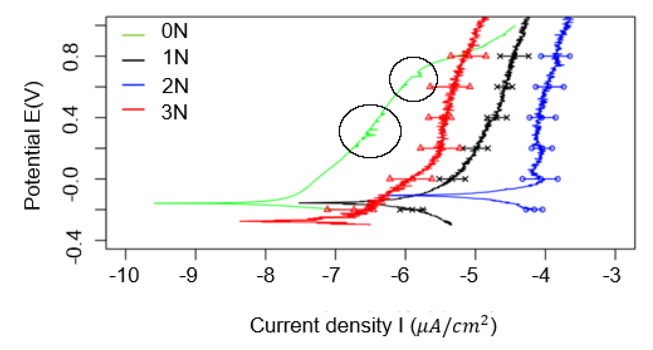
To study the effects of loads applied to the tests, the potentiodynamic polarization experiments were conducted with mechanical rubbing under different loads. The applied load ranged from 1N to 3N. Results can be seen in Figure 2.
The 1N, 2N, and 3N experiments were each repeated three times and the error bars indicate the variations of the current density in these experiments. Acetone was used to remove the passivation layer before the start of each experiment. For the experiment labelled 0N only corrosion occurred, no load was applied, and no sliding occurred. In Figure 2 the section in each curve with the large positive slope indicates formation of a stable passive layer in all the curves, even under the highest load. In contrast, the formation of the passive layer was constantly removed in previous studies due to high contact pressure, and as such did not have this stable passive region. The passive region in the green curve has small horizontal spikes which are circled, showing that pitting occurred in this region. This is the same region for all the three corrosive wear experiments where pitting took place, although the noise due to mechanical wear during the other experiments makes it hard to see this in the curves which experienced corrosive wear. From Figure 2, the test conducted at 3N load had a lower current density than the 1N and 2N load since the corresponding curve for 3N was farther to the left than the 1N and 2N curves. This was partially because of the effects of increased surface area with increased loads due to deformation in the counterpart. Higher contact area results in lower contact pressure, approaching the 30 kPa pressure at perfect contact with the 3N load. If the counterpart was not deformable, contact area would be lower with higher contact pressure, likely generating plastic deformation. Thus, the contact pressure does not necessarily increase linearly with load. Also, the increased contact area would be expected to increase friction, thereby producing more heat. Increased heat kinetically increases the initial corrosion rate, promoting the formation of the passivation layer. The combination of these two is likely the cause of the lower corrosion rate of the 3N load. Future investigation is needed in this phenomenon.
3.2. Formation of Pits
Once the potentiodynamic polarization experiments were completed, surface characterization was conducted using interferometry to analyze pitting of the different samples. Results displayed that the applied load of the mechanical rubbing affected the aspect ratio, i.e., length to width, and size of surface pitting. Images of a reference surface, a corroded surface, and corrosive wear surfaces for the three loads were captured and compared.
Using the interferometry surface profiles, the geometry of pitting was measurable. The size and geometry of the pits generated from the corrosion experiment and the corrosive wear experiments were compared.
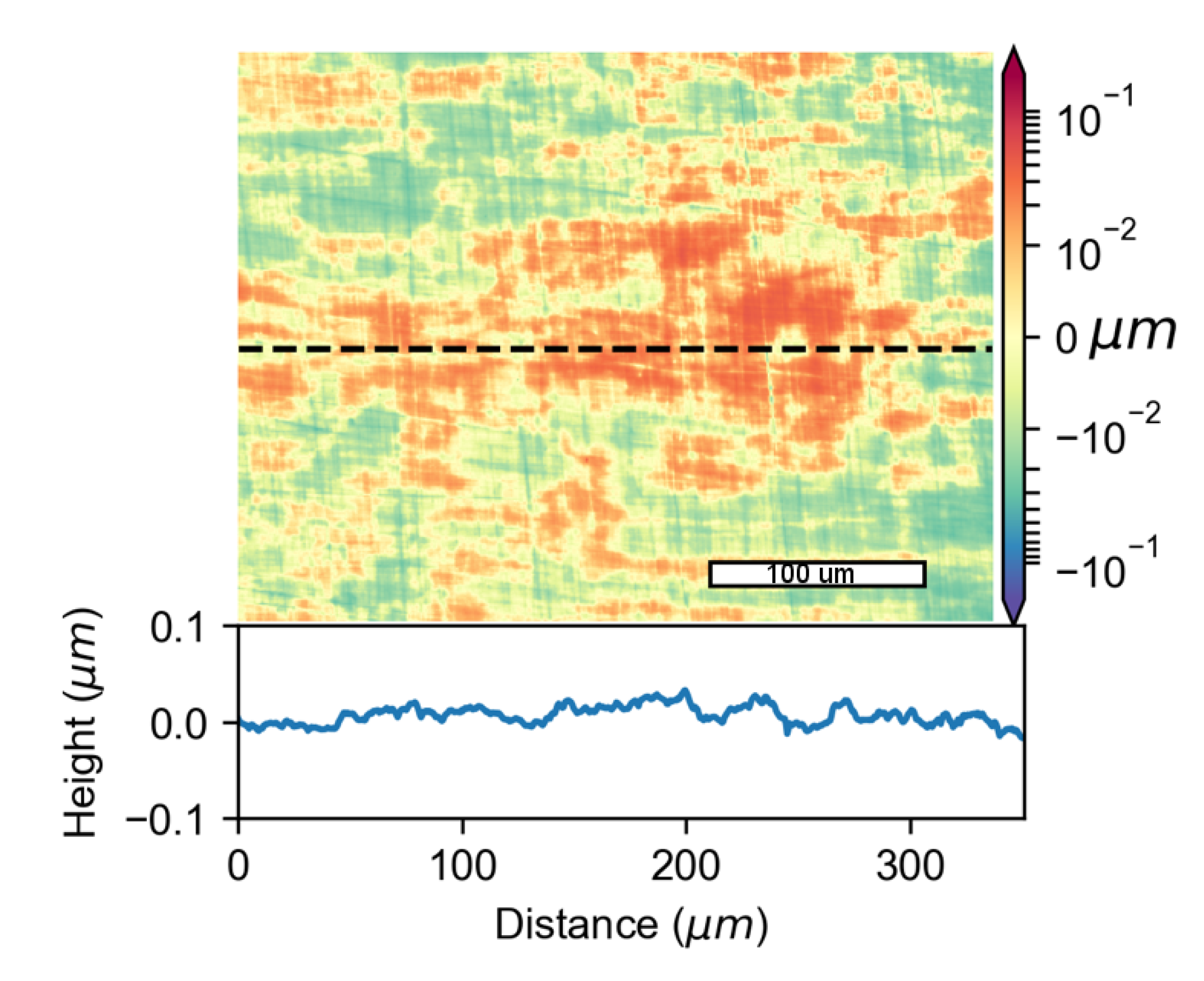
The surfaces of all the test samples were observed in the interferometer prior to corrosion or wear as reference. Results of one such surface are shown in Figure 3. Surface topography is shown in the top part of Figure 3, and the color bar on the right indicates the height range of this plot. Red and blue indicates the areas of the surface at high and low altitudes, respectively. A cross-section profile is shown in the bottom part of Figure 3. Here, the X-axis represents the area indicated by the horizontal dashed line in the top part of Figure 3 and the Y-axis represents the height of each point on the X-axis.
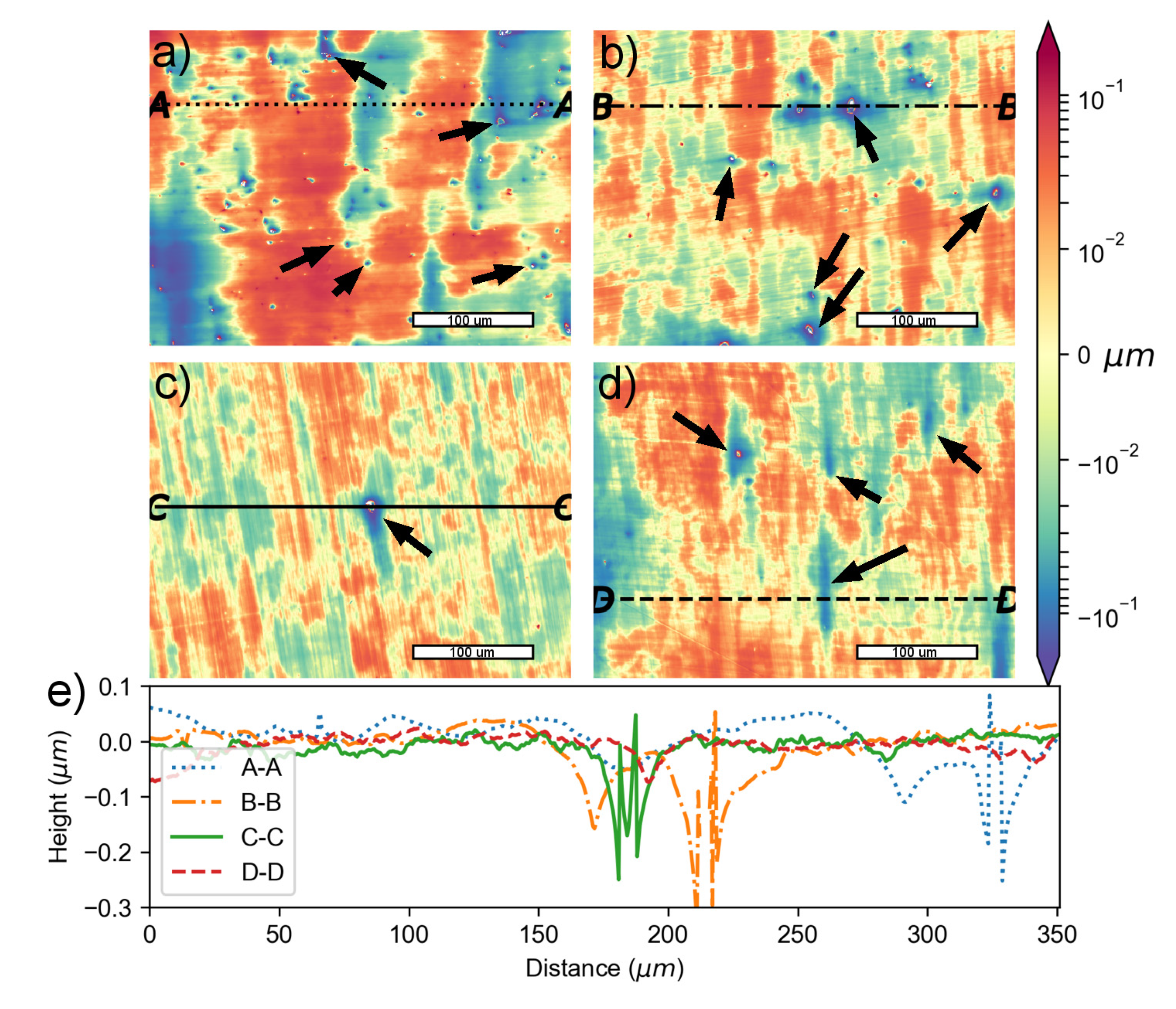
Figure 4 shows topographic images of the surface of each sample after the corrosion and corrosive wear experiments were conducted along with corresponding cross-section profiles. Some of the pits are indicated by the arrows for reference. The top left portion, Figure 4a, displays the topography of the corroded surface with no mechanical wear. Figure 4b (top-right), Figure 4c (bottom-left), and Figure 4d (bottom-right) represent the sample surfaces after the potentiodynamic polarization experiments with mechanical for the 1N, 2N, and 3N load respectively. Figure 4e shows the cross-section profiles for the different experiments at the lines shown. Each line intersects the deepest point on the image of the corresponding sample. Using the interferometry data, 78 pits were measured for the four different experiments: 27 pits from the corrosion tests, 25 pits from the tests with corrosive wear with 1N load, eight from the tests for corrosive wear with 2N load, and 18 from the tests with corrosive wear with 3N load. The 2N and 3N loads had much larger pits, but also had fewer pits. In the sample without corrosion, no pitting was observed on the surface. This data was used to calculate the pitting aspect ratios for the different experiments. These results are further discussed in the following section.
3.3. Pit Transformation
Figure 3 and Figure 4 display the effects of corrosion and tribocorrosion on surface pit growth of the duplex stainless steel for different loads. In Figure 3, the polished reference surface can be considered flat for all practical purposes. It is evident from Figure 4a that several small pits (the small dots) appeared on the sample surface from the corrosion experiment. The pits were mostly randomly oriented oval-like round shapes. They had an average length of 0.0274 mm and a nearly identical average width, implying that nothing influenced pit growth in a specific orientation. Pitting was observed in the potentiodynamic polarization curve (Figure 2) without applying mechanical rubbing, corresponding to these small pits.
As seen in Figure 4b, pitting-like surface defects appeared under mechanical rubbing with a load of 1N load. The light blue stripes are the wear tracks induced by rubbing and indicate the direction of rubbing which was caused by the linearly reciprocating motion. The shape of these pits has is different from the pits in the experiment where only corrosion occurred. However, the orientation of all pits was the same, with their lengths lining up with the rubbing direction. The average length and width of the pits were 0.0378 mm and 0.0282 mm, respectively. The average width here is approximately equal to the average length of the pits in the corrosion experiment, suggesting that even though the light wear did not cause much plastic deformation, the pits were still influenced by the rubbing. This implies that the wear in some way stretched the pits.
The topographic image of a surface after corrosive wear under mechanical rubbing with a load of 2N is shown in Figure 4c. Under this load, the pits are even more visibly elongated in the wear direction than with the 1N load. Wear marks in Figure 4c are also more noticeable than the pits in Figure 4b. The average length of the pits in the rubbing direction was 0.0875 mm, which is more than two times the length of the pits when 1N load was applied and more than three times the length of the pits in the corrosion experiment. Thus, increasing the load to 2N significantly increased the length of the pits. It can be inferred that the 2N load has a significant effect on the shape and growth of the pits in the corrosive environment.
Figure 4d displays the topography of a surface after corrosive wear under mechanical rubbing with a load of 3N. The transformation of the pits is more obvious under this load than with any other load in this study. The size of the pits in the rubbing direction was much larger than the size in the direction perpendicular to the rubbing direction. The average length of the pits in the rubbing direction was 0.0864 mm, surprisingly about the same size as observed for the load of 2N. However, the width of these pits is much smaller. These pits look more like strips. These test samples still experienced low deformation, and yet the increased load greatly affected the pit shapes. Thus, increasing the load during mechanical rubbing has significant effect on pit development.
Figure 4e shows the cross-section profiles of the for the different experiments at the lines shown in Figure 4a–d. Each line intersects the deepest point on the corresponding sample image, i.e., the deepest pit. These profiles show the pits increased in depth going from the corrosion experiment (blue line) to the corrosive wear experiment with a 1N load (orange line). However, when the load is increased to 2N the pit depth decreases, and at 3N the pit is significantly shallower than for any other experiment. Some of the cross-section profiles in Figure 4e protrude back upwards in the deep portion of the pit. This is due to the lack of precise imaging with the interferometer at deep points in the pits.
In this research we experimentally studied the initiation of tribochemical wear of a duplex steel. This type of steel is known to have localized corrosion such as pitting. Compared to the static corrosion, tribocorrosion promoted oxidation and formation of a passive layer, yet also breakage of this layer. As a result, elongated pits were discovered.
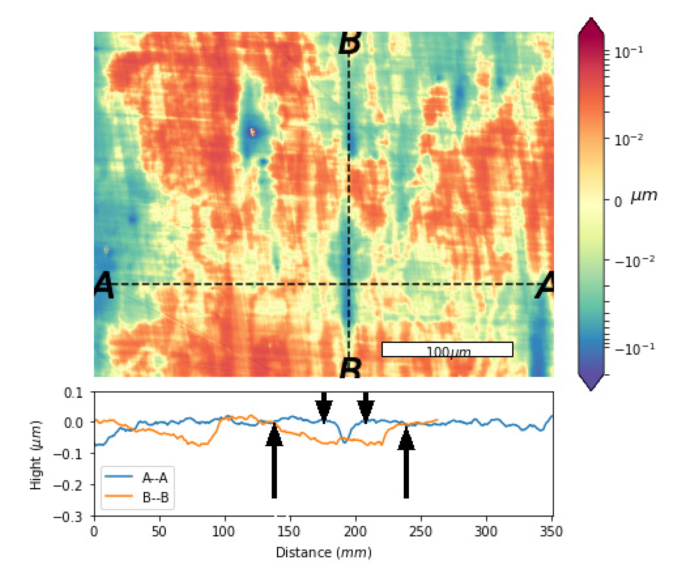
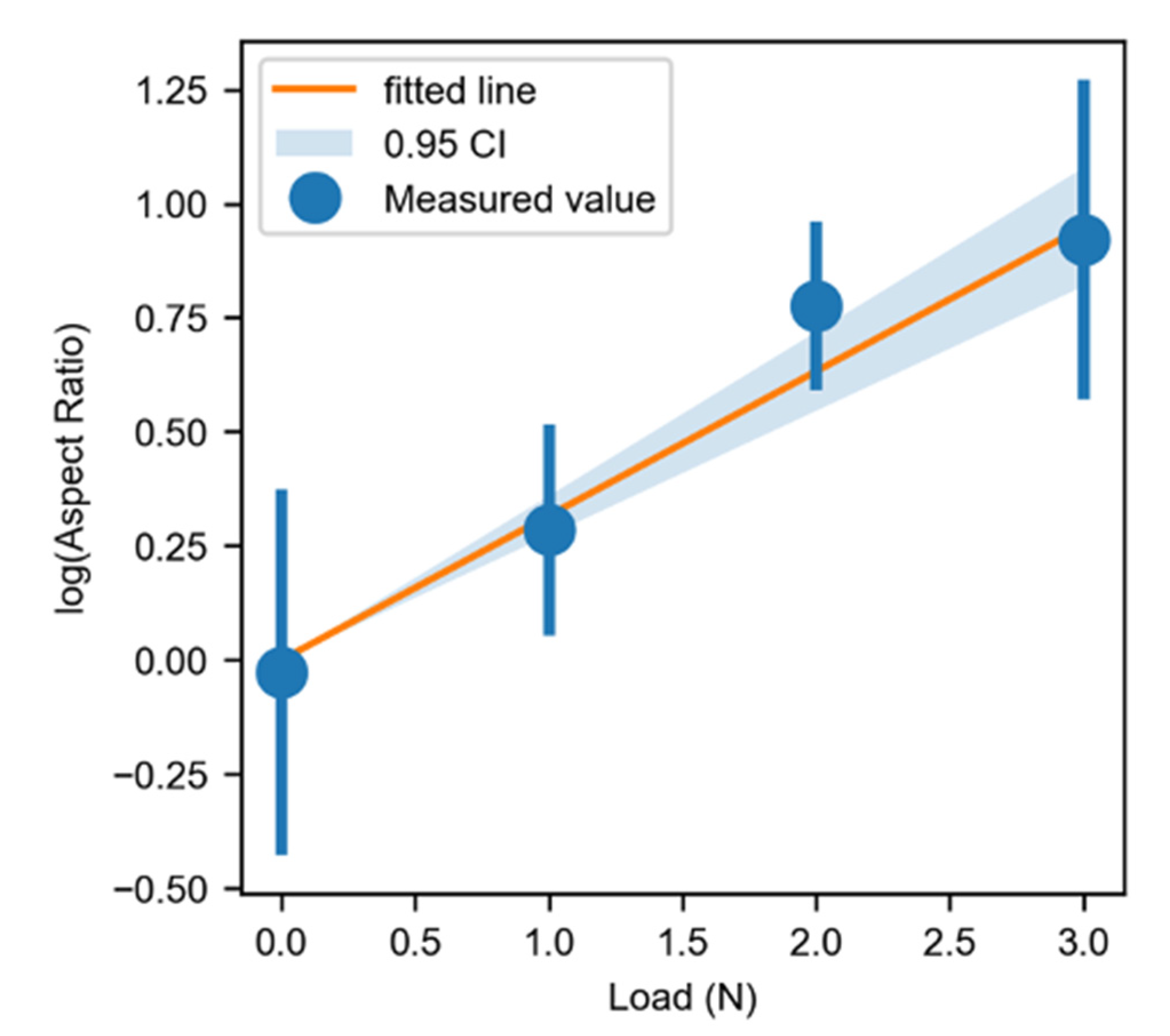
The pit lengths and widths for each surface were measured and their aspect ratios were calculated. The method was accomplished as shown in Figure 5. The 2D profile of each pit’s width and length was plotted, and the two distances were measured, starting at the point the altitude dropped below the average altitude of the 2D profile. These points are shown on one such pit with black arrows on the 2D profile plots. A 0.95 confidence interval of the natural logarithm of the aspect ratios was plotted against the applied load along with the measured values, as shown in Figure 6. These aspect ratios were calculated based on interferometry images.
In Figure 6, for no applied load the log of the aspect ratio is zero, corresponding to an aspect ratio of one. This agrees with physics and logical deduction, as there was no load to influence the growth of the pits in one direction over the other. Since the confidence interval intersects each set of data, it is clear that the data fits a linear trend with 95% confidence. Therefore, since the Y-axis is a logarithmic scale, it appears that pit ratio increases at an exponential rate with applied load. The equation of this fit is as follows (Equation (1)):
Aspect Ratio = exp (3.163 × load),
This equation implies that at a low load range, the pits’ aspect ratios increase exponentially with load. This would likely occur with the lengthening of pits and narrowing of the width like what was seen between the 2N and 3N experiments. However, the length may stop growing since it did not remain constant between the 2N and 3N experiments. Meanwhile, loads under 1N would result in pits approaching an aspect ratio of 1. The reason for this relationship is unclear. Duplex stainless steel’s two-phase microstructure may have some influence on the pit growths, as one phase is often targeted for pitting over the other [38]. Another possible influence of pit growth is the ion distribution across the pits, which may be affected in the wear direction while not in the direction perpendicular to the wear. The detailed mechanisms of this behavior are not clear, and more work is needed in the future.
4. Conclusions
The effects of the combination of corrosion and friction on pitting of duplex stainless steel 2205 were studied using an integrated triboelectrochemical approach. A mild rubbing condition in the 3.5 wt% salt solution was achieved through the experimental design. Results showed that mechanical rubbing promoted the formation of a passivation layer over that in the corrosion experiment. This was due to the activation of the surface through rubbing. However, this also induced the formation of pitting in the same passive region. Furthermore, the shape of the pits was found to be affected by contact pressure during sliding. In a corrosive environment without mechanical rubbing, the pits were round with an average diameter of 27.4 µm. When a load of 1N was applied, the pits mostly maintained the round shapes with an average diameter of 37.8 µm. By increasing the loads to 2N and 3N, the pits further developed in the rubbing direction. Under a load of 2N, the average length of the pits in the rubbing direction was 87.5μm, and under a load of 3N it was about the same at 86.4μm. Mechanical rubbing elongated these pits, increasing the aspect ratio exponentially with load. Mechanical rubbing promoted competing processes of passivating and pitting. Further development of pitting could result in catastrophic failure of structural integrity. Understanding the formation and propagation of pitting during corrosive wear is vital to preventing and mitigating failure. Future research will investigate other factors such as velocity and temperature. This research reveals that the initiation of tribochenical wear of duplex stee is actually altered pitting. This discovery would be beneficial to improve the design of alloys against corrosive wear environments.
Author Contributions
Conceptualization, H.L.; methodology, P.R., Y.C., Z.H., H.L.; software, Y.C., P.R.; validation, P.R., Y.C. and Z.H.; formal analysis, P.R. and Y.C.; investigation, P.R., Y.C., and Z.H.; writing—original draft preparation, P.R., Y.C., Z.H; writing—review and editing, A.R. and H.L.; supervision, H.L. All authors have read and agreed to the published version of the manuscript.
Funding
PAR was sponsored by the National Science Foundation Graduate Research Fellowship Program. Z.H. and Y.C. were awarded the STLE-Houston Session scholarship in 2015 and 2018, respectively.
Institutional Review Board Statement
Not applicable.
Informed Consent Statement
Not applicable.
Data Availability Statement
The data presented in this study are available on request from the corresponding author.
Acknowledgments
Authors would like to acknowledge the support by Alex Fang, Wei Dai, and Huaping Xiao for assisting in the experiments.
Conflicts of Interest
The authors declare no conflict of interest.
References
- Tuttle, R. Corrosion in Oil and Gas Production. J. Pet. Technol. 1987, 39, 756–762. [Google Scholar] [CrossRef]
- Kurtz, R.S. Oil Pipeline Regulation, Culture, and Integrity: The 2006 BP North Slope Spill. Public Integr. 2010, 13, 25–40. [Google Scholar] [CrossRef]
- Martínez, D.; Gonzalez, R.; Montemayor, K.; Juarez-Hernandez, A.; Fajardo, G.; Hernandez-Rodriguez, M. Amine Type Inhibitor Effect on Corrosion–Erosion Wear in Oil Gas Pipes. Wear 2009, 267, 255–258. [Google Scholar] [CrossRef]
- Barker, R.J.; Hu, X.; Neville, A.; Cushnaghan, S. Empirical Prediction of Carbon-Steel Degradation Rates on an Offshore Oil and Gas Facility: Predicting CO2 Erosion-Corrosion Pipeline Failures before They Occur. SPE J. 2014, 19, 425–436. [Google Scholar] [CrossRef]
- Hu, X.; Neville, A. CO2 Erosion–Corrosion of Pipeline Steel (API X65) in Oil and Gas Conditions—A Systematic Approach. Wear 2009, 267, 2027–2032. [Google Scholar] [CrossRef]
- Farrell, A.J.; Norton, B.; Kennedy, D.M. Corrosive Effects of Salt Hydrate Phase Change Materials Used with Aluminium and Copper. J. Mater. Process. Technol. 2006, 175, 198–205. [Google Scholar] [CrossRef]
- Hernandez-Rodriguez, M.; Martinez-Delgado, D.; Gonzalez, R.; Unzueta, A.P.; Mercado-Solís, R.; Rodriguez, J. Corrosive Wear Failure Analysis in a Natural Gas Pipeline. Wear 2007, 263, 567–571. [Google Scholar] [CrossRef]
- Mercer, W.E.; Hillis, J.E. The Critical Contaminant Limits and Salt Water Corrosion Performance of Magnesium AE42 Alloy; SAE Technical Paper; SAE 1992 International Congress and Exposition: Detroit, MI, USA, 1992. [Google Scholar]
- Bello, J.; Wood, R.; Wharton, J. Synergistic Effects of Micro-Abrasion–Corrosion of UNS S30403, S31603 and S32760 Stainless Steels. Wear 2007, 263, 149–159. [Google Scholar] [CrossRef] [Green Version]
- Yan, Y.; Neville, A.; Dowson, D.; Williams, S. Tribocorrosion in Implants—Assessing High Carbon and Low Carbon Co–Cr–Mo Alloys by in Situ Electrochemical Measurements. Tribol. Int. 2006, 39, 1509–1517. [Google Scholar] [CrossRef]
- Galliano, F.; Galvanetto, E.; Mischler, S.; Landolt, D. Tribocorrosion Behavior of Plasma Nitrided Ti–6Al–4V Alloy in Neutral NaCl Solution. Surf. Coat. Technol. 2001, 145, 121–131. [Google Scholar] [CrossRef]
- Benea, L.; Wenger, F.; Ponthiaux, P.; Celis, J.-P. Tribocorrosion Behaviour of Ni–SiC Nano-Structured Composite Coatings Obtained by Electrodeposition. Wear 2009, 266, 398–405. [Google Scholar] [CrossRef]
- Gao, F.; Liang, H. Effects of Potential and Mechanical Stimulation on Oxidation of Tantalum during Electrochemical Mechanical Polishing. J. Electron. Mater. 2012, 41, 624–631. [Google Scholar] [CrossRef]
- Gao, F.; Liang, H. Transformable Oxidation of Tantalum in Electrochemical Mechanical Polishing (ECMP). J. Electron. Mater. 2011, 40, 134–140. [Google Scholar] [CrossRef]
- Gao, F.; Liang, H. Material Removal Mechanisms in Electrochemical–Mechanical Polishing of Tantalum. Electrochim. Acta 2009, 54, 6808–6815. [Google Scholar] [CrossRef]
- Ng, D.; Sen, T.; Gao, F.; Liang, H. Friction and Wear-Mode Comparison in Copper Electrochemical Mechanical Polishing. J. Electrochem. Soc. 2008, 155, H520. [Google Scholar] [CrossRef]
- Ng, D.; Kulkarni, M.; Johnson, J.; Zinovev, A.; Yang, D.; Liang, H. Oxidation and Removal Mechanisms during Chemical–Mechanical Planarization. Wear 2007, 263, 1477–1483. [Google Scholar] [CrossRef]
- Kulkarni, M.; Greisen, D.; Ng, D.; Liang, H. New Approaches in Investigation of Removal Mechanisms during Copper Chemical-Mechanical Polishing. J. ASTM Int. 2006, 3, 1–7. [Google Scholar]
- Xu, G.H.; Liang, H. Effects of Electric Potential on Chemical-Mechanical Polishing of Copper. J. Electron. Mater. 2002, 31, 272–277. [Google Scholar] [CrossRef]
- Kar, P.; Asthana, P.; Liang, H. Formation and Characterization of Tribofilms. J. Tribol. 2008, 130. [Google Scholar] [CrossRef]
- Kar, P.; Wang, K.; Liang, H. Force-Dominated Non-Equilibrium Oxidation Kinetics of Tantalum. Electrochim. Acta 2008, 53, 5084–5091. [Google Scholar] [CrossRef]
- Kar, P.; Wang, K.; Liang, H. Oxidation of Tantalum with Mechanical Force. Electrochem. Solid State Lett. 2007, 11, C13. [Google Scholar] [CrossRef]
- Kulkarni, M.; Gao, F.; Liang, H. Chemical-mechanical polishing (CMP): A controlled tribocorrosion process. In Tribocorrosion of Passive Metals and Coatings; Elsevier: Amsterdam, The Netherlands, 2011; pp. 498–516, 517e–518e. [Google Scholar]
- Zhou, Y.; Engelberg, D.L. Fast Testing of Ambient Temperature Pitting Corrosion in Type 2205 Duplex Stainless Steel by Bipolar Electrochemistry Experiments. Electrochem. Commun. 2020, 117, 106779. [Google Scholar] [CrossRef]
- Chen, L.; Tan, H.; Wang, Z.; Li, J.; Jiang, Y. Influence of Cooling Rate on Microstructure Evolution and Pitting Corrosion Resistance in the Simulated Heat-Affected Zone of 2304 Duplex Stainless Steels. Corros. Sci. 2012, 58, 168–174. [Google Scholar] [CrossRef]
- Tan, H.; Jiang, Y.; Deng, B.; Sun, T.; Xu, J.; Li, J. Effect of Annealing Temperature on the Pitting Corrosion Resistance of Super Duplex Stainless Steel UNS S32750. Mater. Charact. 2009, 60, 1049–1054. [Google Scholar] [CrossRef]
- Potgieter, J. Influence of σ Phase on General and Pitting Corrosion Resistance of SAF 2205 Duplex Stainless Steel. Br. Corros. J. 1992, 27, 219–223. [Google Scholar] [CrossRef]
- Sriram, R.; Tromans, D. Pitting Corrosion of Duplex Stainless Steels. Corrosion 1989, 45, 804–810. [Google Scholar] [CrossRef]
- Fargas, G.; Mestra, A.; Mateo, A. Effect of Sigma Phase on the Wear Behavior of a Super Duplex Stainless Steel. Wear 2013, 303, 584–590. [Google Scholar] [CrossRef]
- Paro, J.; Hänninen, H.; Kauppinen, V. Tool Wear and Machinability of HIPed P/M and Conventional Cast Duplex Stainless Steels. Wear 2001, 249, 279–284. [Google Scholar] [CrossRef]
- Pereira Neto, J.O.; da Silva, R.O.; da Silva, E.H.; Moreto, J.A.; Bandeira, R.M.; Manfrinato, M.D.; Rossino, L.S. Wear and Corrosion Study of Plasma Nitriding F53 Super Duplex Stainless Steel. Mater. Res. 2016, 19, 1241–1252. [Google Scholar] [CrossRef] [Green Version]
- Hunter, J.D. Matplotlib: A 2D Graphics Environment. Comput. Sci. Eng. 2007, 9, 90–95. [Google Scholar] [CrossRef]
- Seabold, S.; Perktold, J. Statsmodels: Econometric and Statistical Modeling with Python. In Proceedings of the 9th Python in Science Conference (SciPy), Austin, TX, USA, 28–30 July 2010; p. 61. [Google Scholar]
- Liu, Z.; Dong, C.; Li, X.; Zhi, Q.; Cheng, Y. Stress Corrosion Cracking of 2205 Duplex Stainless Steel in H2S–CO2 Environment. J. Mater. Sci. 2009, 44, 4228–4234. [Google Scholar] [CrossRef]
- Park, C.; Rao, V.S.; Kwon, H.-S. Effects of Sigma Phase on the Initiation and Propagation of Pitting Corrosion of Duplex Stainless Steel. Corrosion 2005, 61, 76–83. [Google Scholar] [CrossRef]
- Moura, V.; Lima, L.; Pardal, J.; Kina, A.; Corte, R.; Tavares, S. Influence of Microstructure on the Corrosion Resistance of the Duplex Stainless Steel UNS S31803. Mater. Charact. 2008, 59, 1127–1132. [Google Scholar] [CrossRef]
- Nilsson, J.-O.; Karlsson, L.; Andersson, J.-O. Secondary Austenite for Mation and Its Relation to Pitting Corrosion in Duplex Stainless Steel Weld Metal. Mater. Sci. Technol. 1995, 11, 276–283. [Google Scholar] [CrossRef]
- Garfias-Mesias, L.; Sykes, J.; Tuck, C. The Effect of Phase Compositions on the Pitting Corrosion of 25 Cr Duplex Stainless Steel in Chloride Solutions. Corros. Sci. 1996, 38, 1319–1330. [Google Scholar] [CrossRef]
Figure 1.
An illustration of the new configuration for tribocorrosion experiments. It contains a pair of flat rubbing parts, a tribometer, and an electrochemical workstation. The test sample rubs against the counterpart in a linear reciprocating motion.
Figure 1.
An illustration of the new configuration for tribocorrosion experiments. It contains a pair of flat rubbing parts, a tribometer, and an electrochemical workstation. The test sample rubs against the counterpart in a linear reciprocating motion.

Figure 2.
The potentiodynamic polarization curves for the four experiments. Pitting in the corrosion experiment is shown by the horizontal spikes in the curve, which are circled.
Figure 2.
The potentiodynamic polarization curves for the four experiments. Pitting in the corrosion experiment is shown by the horizontal spikes in the curve, which are circled.

Figure 3.
Topography of surface and profile of cross-section after polishing.

Figure 4.
(a) Topography after the corrosion experiment; (b) topography after the corrosive wear experiments with 1N; (c) 2N; and (d) 3N loads. (e) Below the topography images, the profile of the cross-sections of lines A-A, B-B, C-C, and D-D are compared. Those lines were selected because they went across at least one pit. Some pits are indicated by arrows for reference.

Figure 5.
An example of how pit aspect ratio was calculated. The arrows show how the width and length were individually measured. The 2D profiles for length and width are labelled B-B and A-A, respectively.
Figure 5.
An example of how pit aspect ratio was calculated. The arrows show how the width and length were individually measured. The 2D profiles for length and width are labelled B-B and A-A, respectively.

Figure 6.
The log of the aspect ratios versus the applied load, fitted with a 0.95 confidence interval.
Figure 6.
The log of the aspect ratios versus the applied load, fitted with a 0.95 confidence interval.


Table 1.
Tribology test conditions.
| Parameter | Value |
|---|---|
| Load | 0, 1, 2, 3N |
| Speed | 0.5 cm/s (max) |
| Distance | 3 cm |
| Contact area | 1 cm2 |
| Temperature | 24 °C |
Table 2.
Corrosion test parameters.
| Parameter | Value |
|---|---|
| Potential (vs. Vref) | −0.2 V to 1.2 V |
| Scanning rate | 2 mV/s |
| Sample period | 700 s |
| Conditioning time | 60 s |
Publisher’s Note: MDPI stays neutral with regard to jurisdictional claims in published maps and institutional affiliations. |
© 2021 by the authors. Licensee MDPI, Basel, Switzerland. This article is an open access article distributed under the terms and conditions of the Creative Commons Attribution (CC BY) license (https://creativecommons.org/licenses/by/4.0/).
Share and Cite
MDPI and ACS Style
Renner, P.; Chen, Y.; Huang, Z.; Raut, A.; Liang, H. Tribocorrosion Influenced Pitting of a Duplex Stainless Steel. Lubricants 2021, 9, 52. https://0-doi-org.brum.beds.ac.uk/10.3390/lubricants9050052
AMA Style
Renner P, Chen Y, Huang Z, Raut A, Liang H. Tribocorrosion Influenced Pitting of a Duplex Stainless Steel. Lubricants. 2021; 9(5):52. https://0-doi-org.brum.beds.ac.uk/10.3390/lubricants9050052
Chicago/Turabian StyleRenner, Peter, Yan Chen, Zhihao Huang, Ajinkya Raut, and Hong Liang. 2021. "Tribocorrosion Influenced Pitting of a Duplex Stainless Steel" Lubricants 9, no. 5: 52. https://0-doi-org.brum.beds.ac.uk/10.3390/lubricants9050052
Note that from the first issue of 2016, this journal uses article numbers instead of page numbers. See further details here.