Effect of Intercritical Annealing and Austempering on the Microstructure and Mechanical Properties of a High Silicon Manganese Steel

 , , ,
, , ,
Abstract
:1. Introduction
Novelty of the Work
2. Materials and Methods
2.1. Heat Treatments
- i.
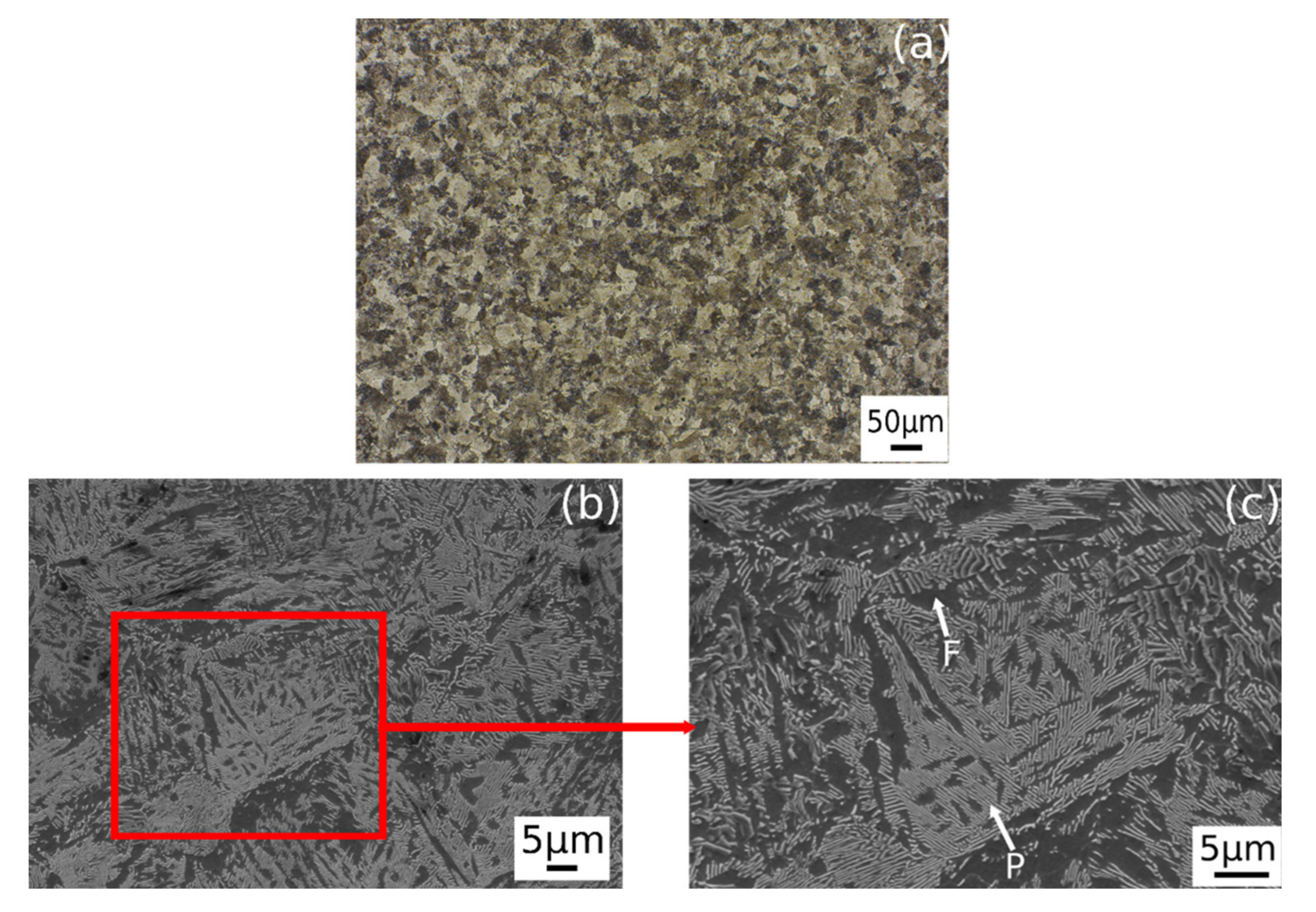
- Annealing: heating at 870 °C at 1 °C/s, 10 min holding time and furnace cooling (0.15 °C/s).
- ii.
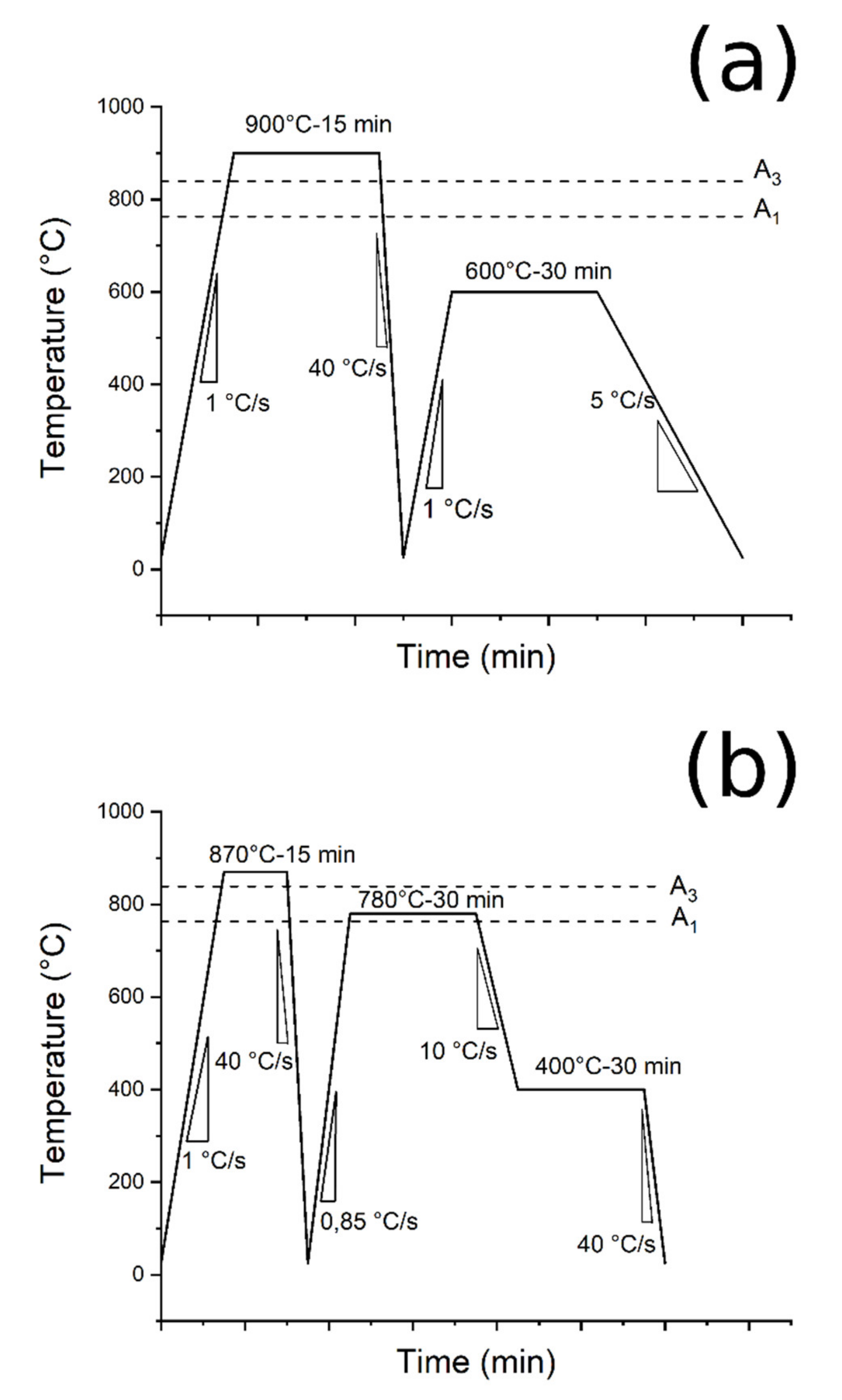
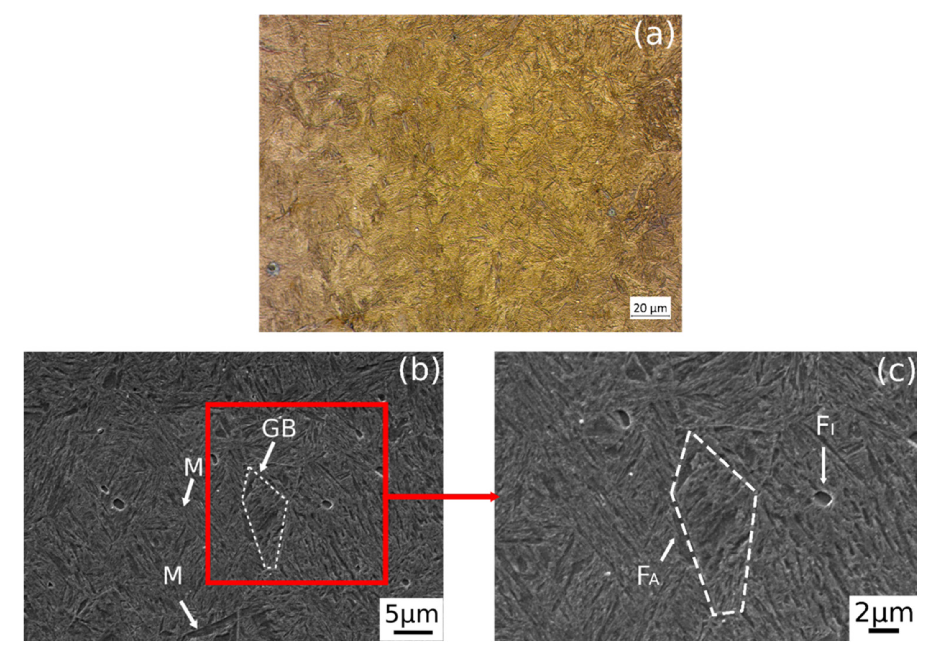
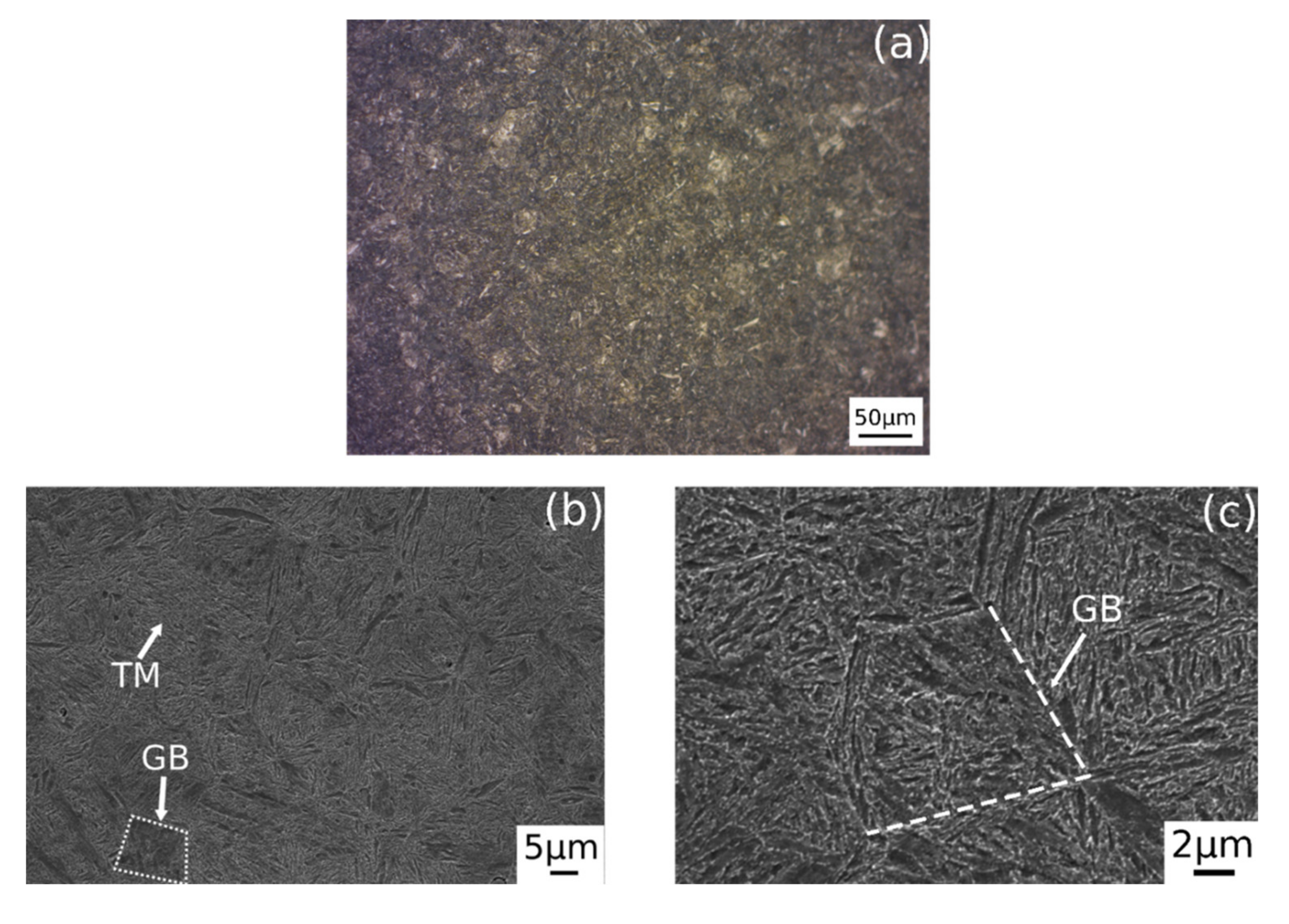
- Quenching and tempering (Q&T): heating at 900 °C at 1 °C/s, 15 min dwell time, and water quenching (cooling rate: 40 °C/s); tempering at 600°C for 30 min and air cooling (5 °C/s) (Figure 3a).
- iii.
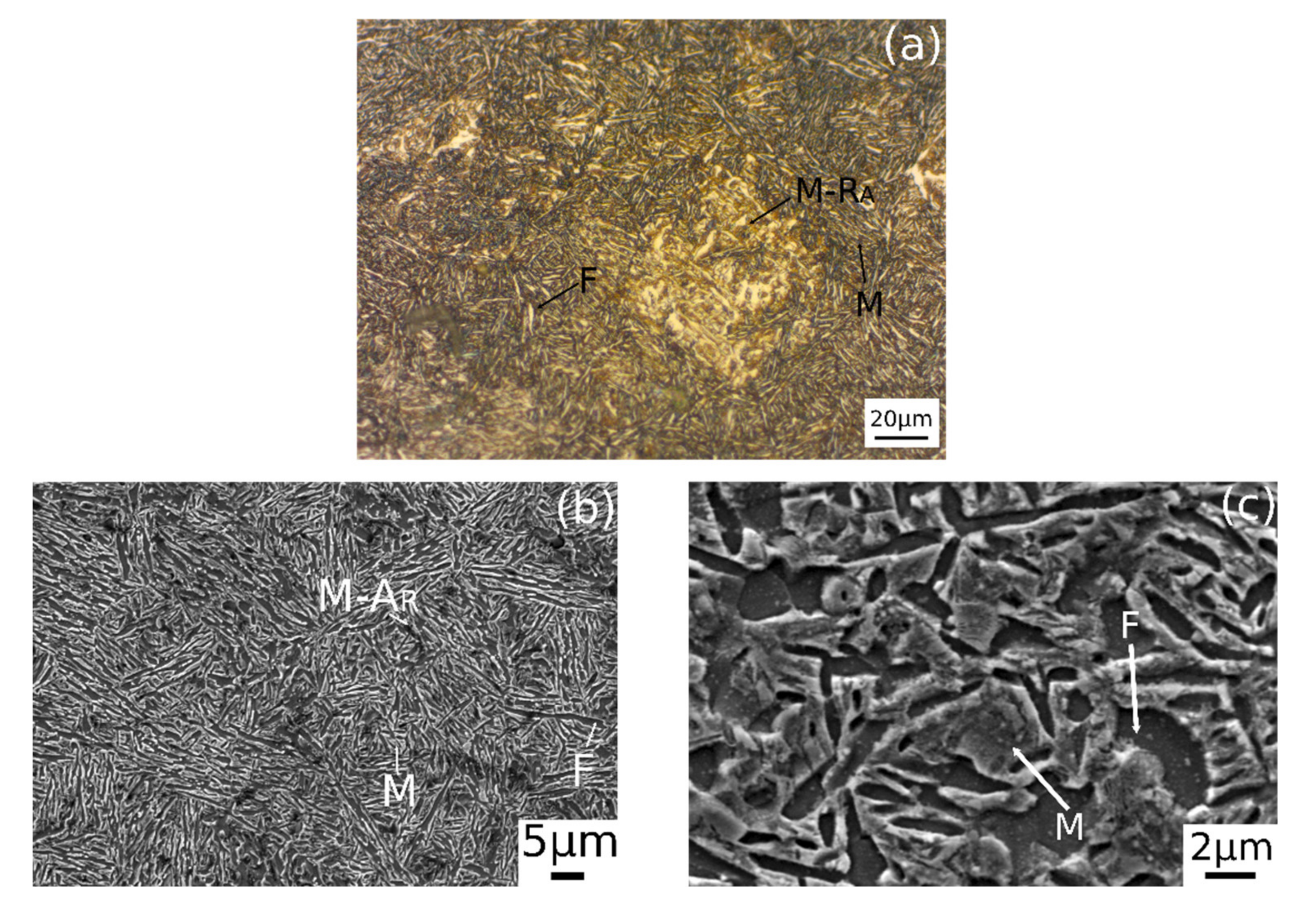
- Intercritical Annealing and Austempering (IA&A): Pre-quenching treatment from 870 °C (15 min) and water cooling. Heating at 780 °C for 30 min at 0.8 °C/s, air cooling at 10 °C/s to 400 °C and holding for 30 min followed by water cooling to room temperature at 40 °C/s (Figure 3b).
2.2. Microstructural Study
2.3. Mechanical Tests
3. Results
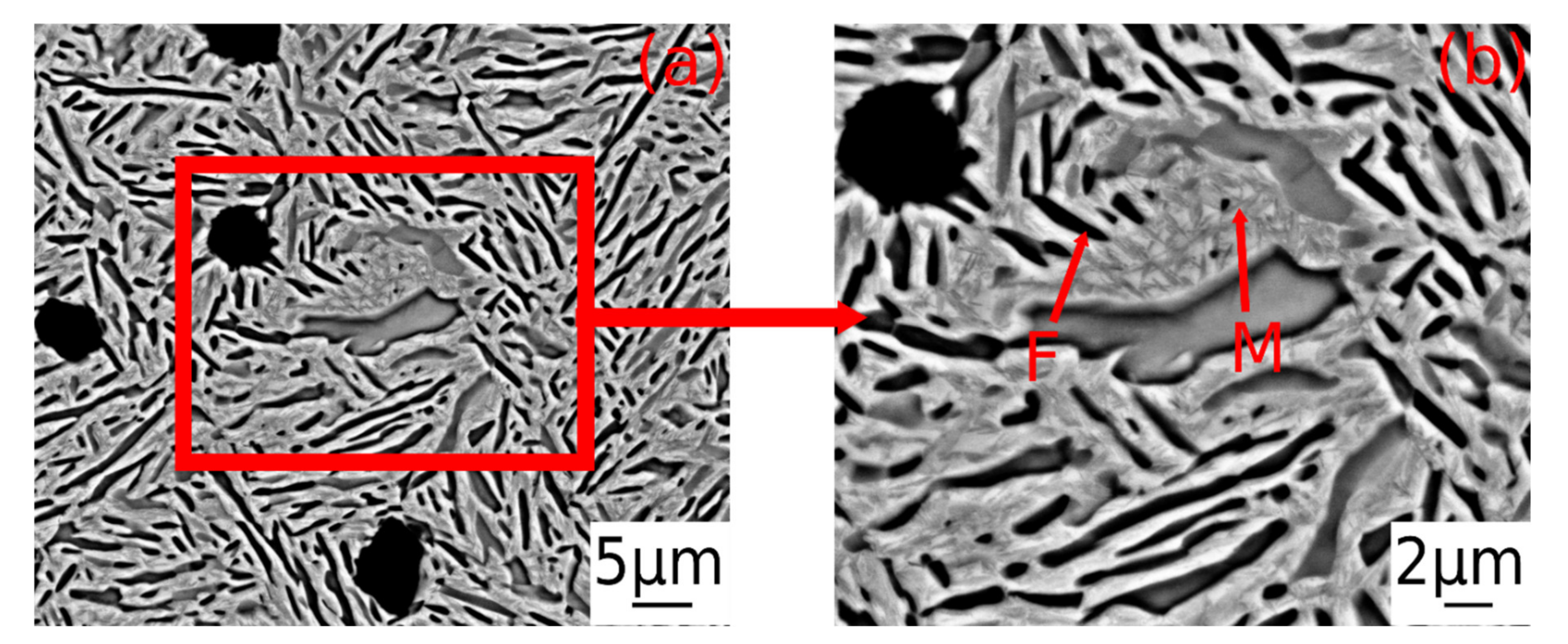
3.1. Microstructure
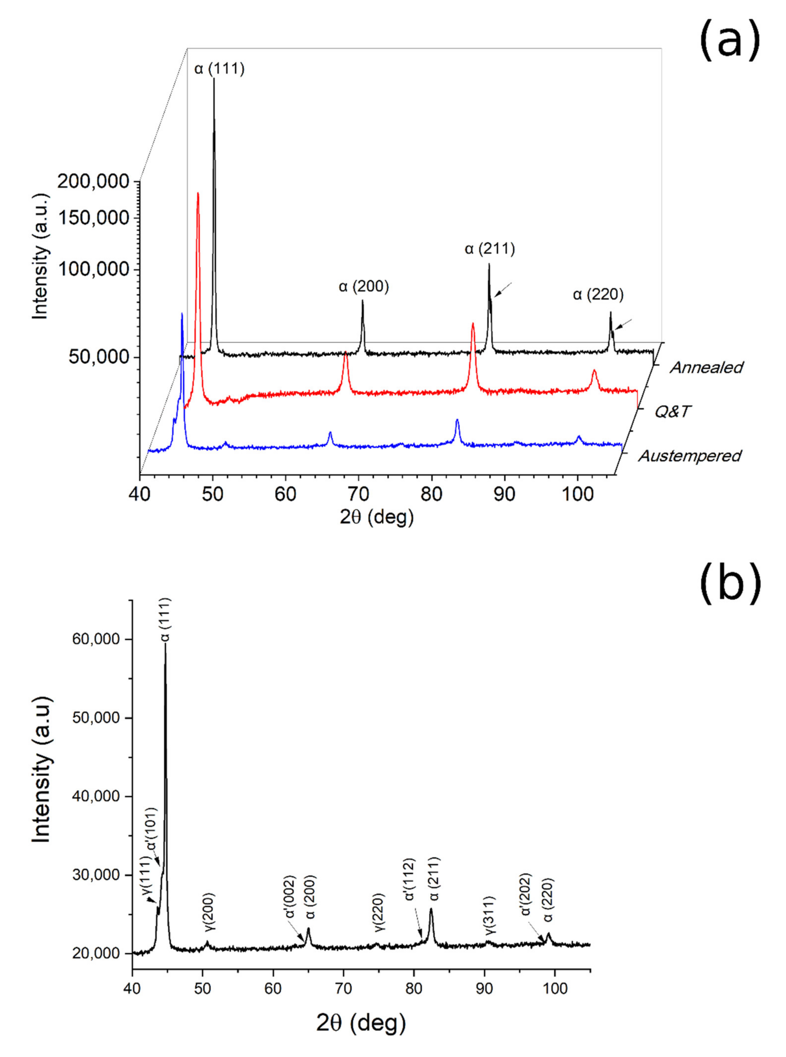
3.2. X-ray Diffraction
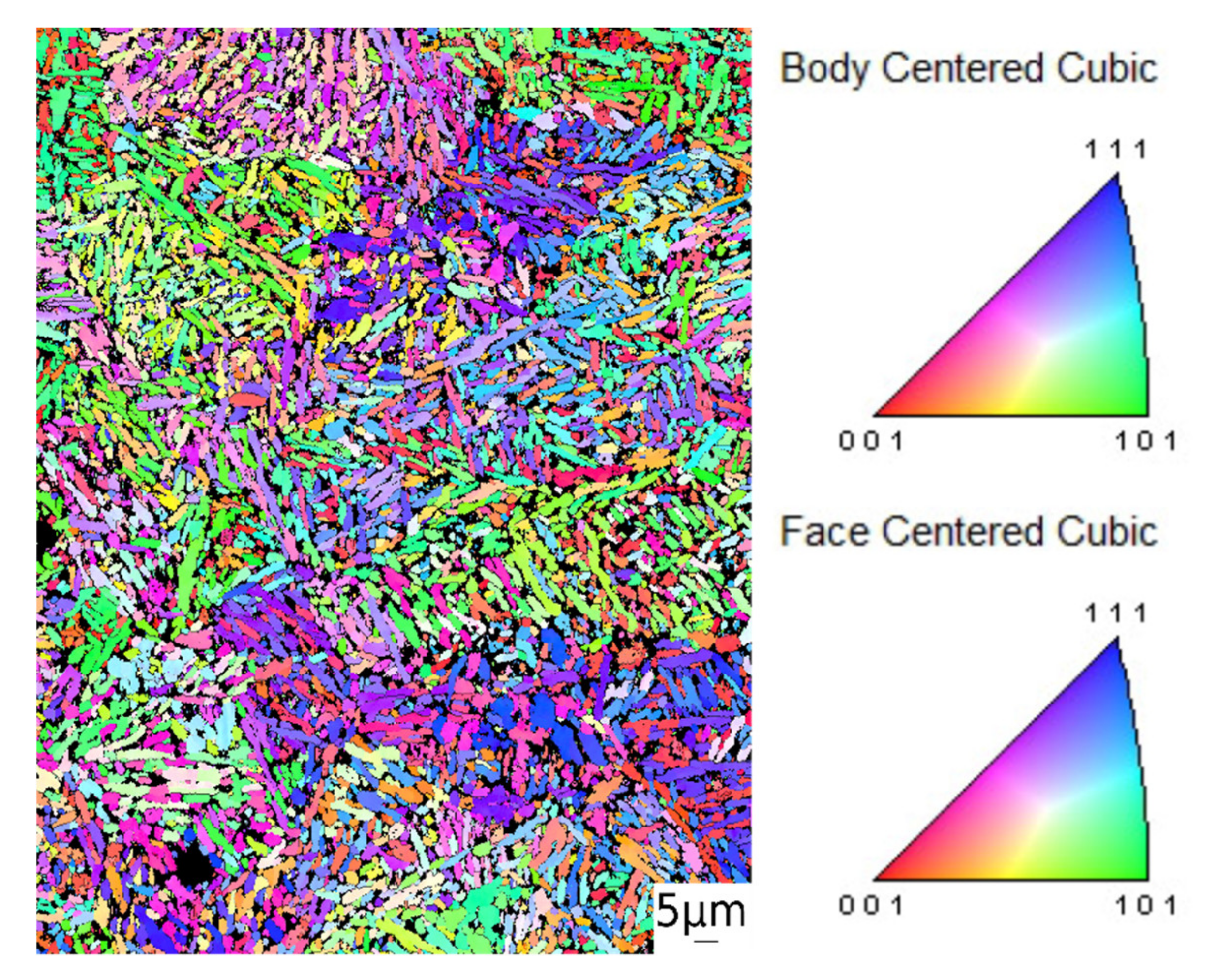
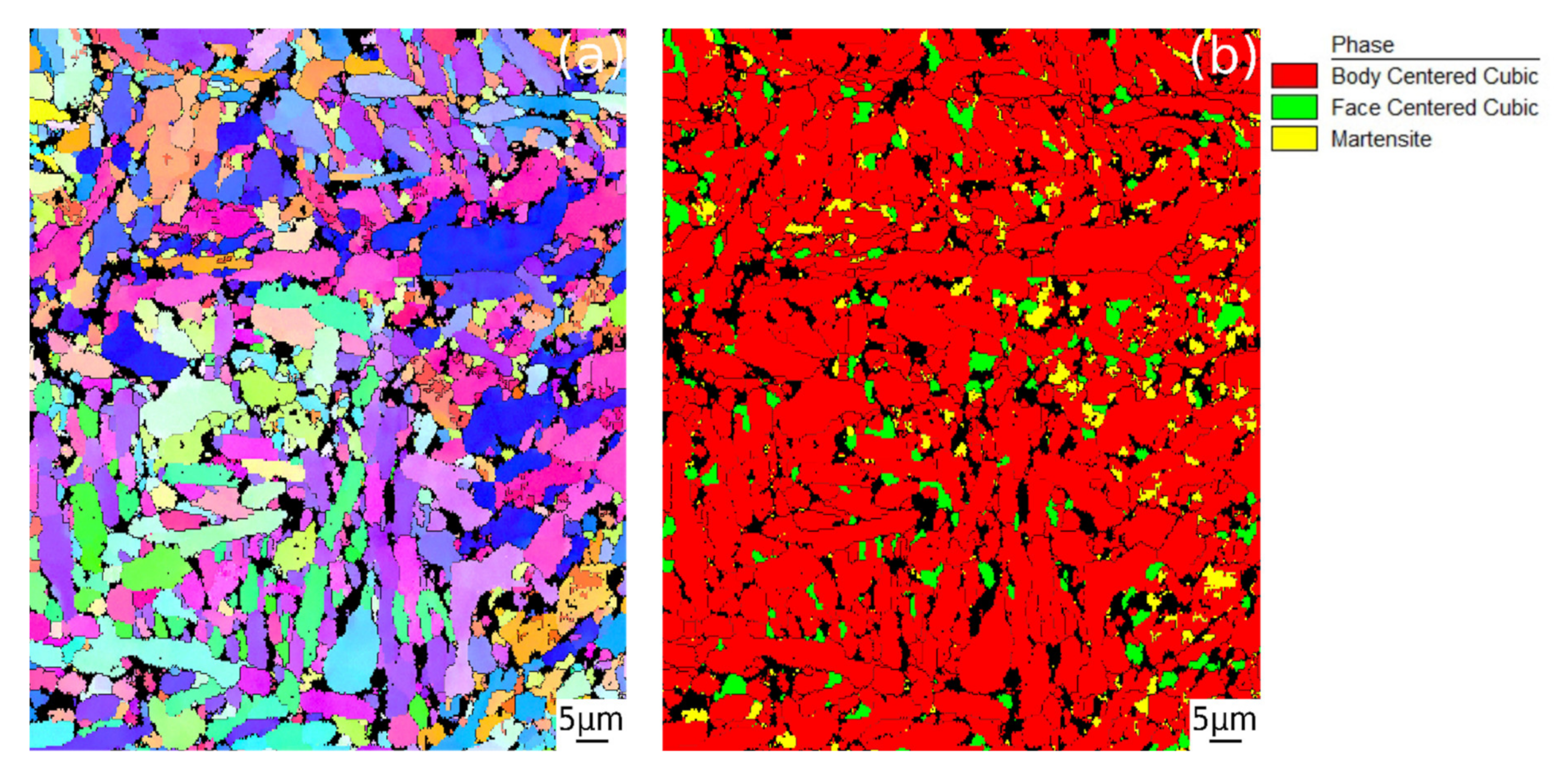
3.3. Electron BackScattered Diffraction
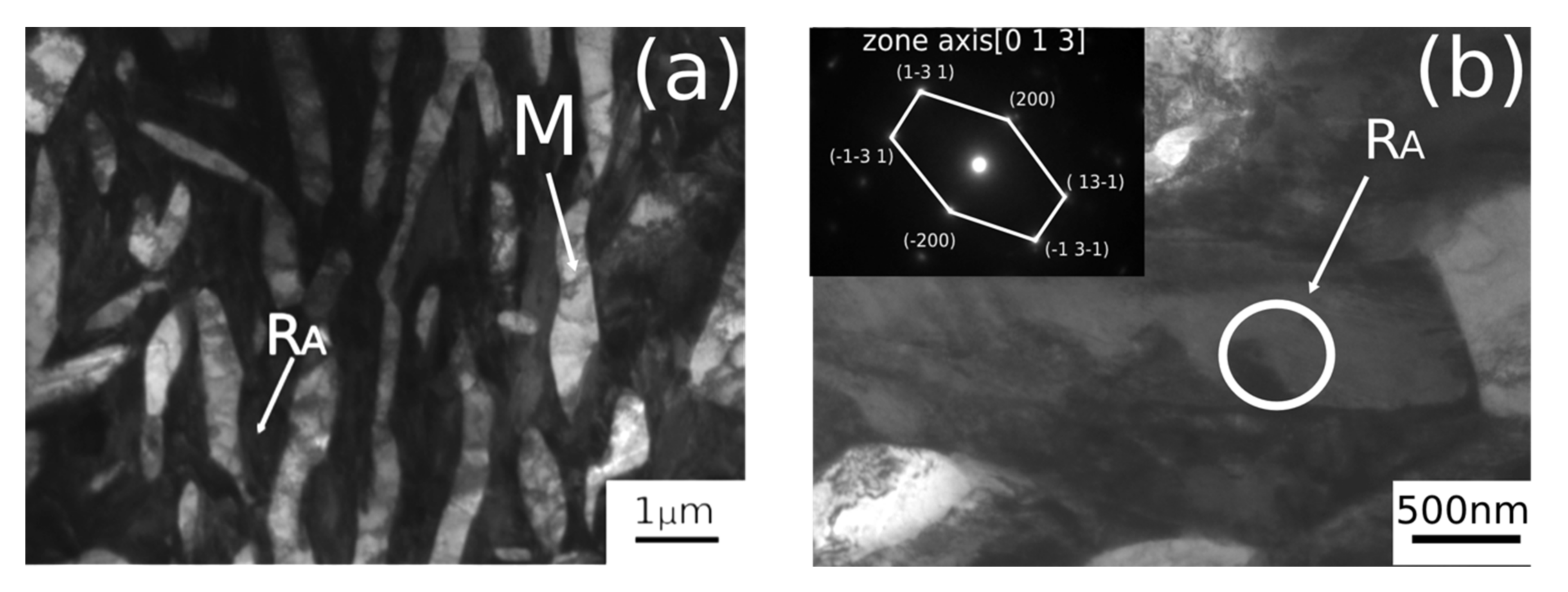
3.4. Transmission Electron Microscopy
3.5. Mechanical Properties
3.5.1. Microhardness Test
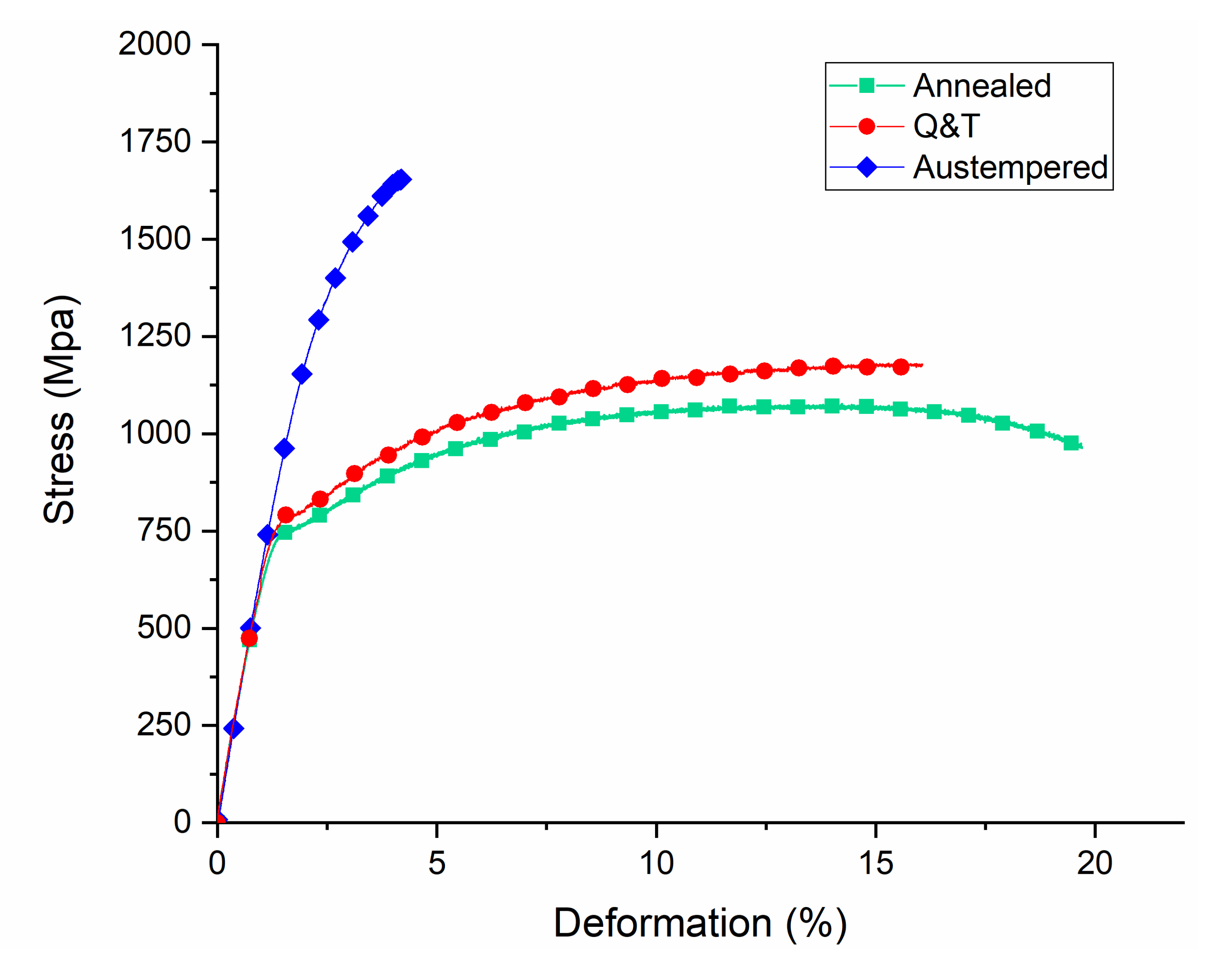
3.5.2. Tensile Tests
4. Discussion
4.1. Austempering Treatment
4.2. Microstructure and Mechanical Properties
5. Conclusions
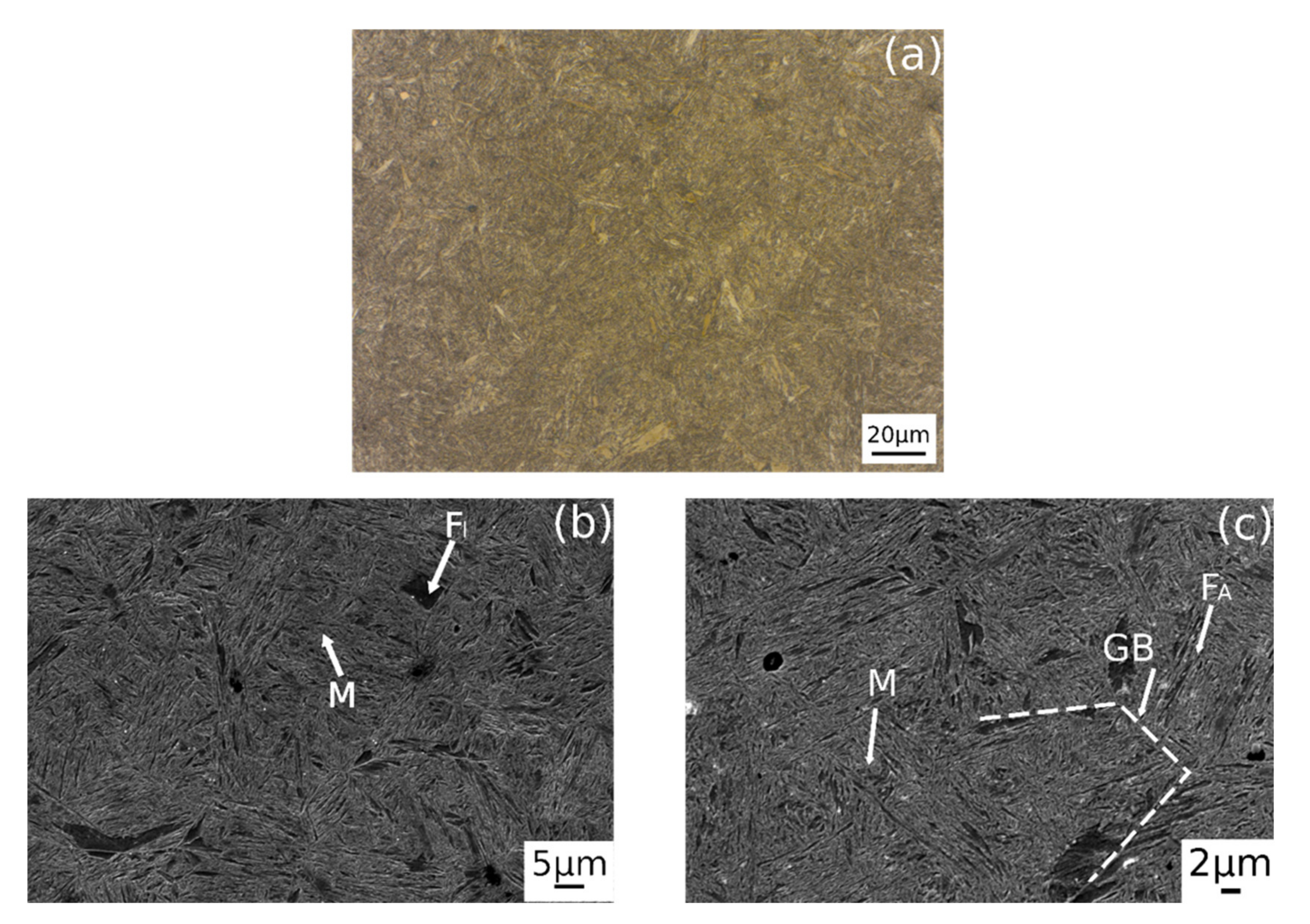
- A novel high silicon steel with multiphase microstructure composed by ferrite, tetragonal martensite, and retained austenite was developed. Austempering treatment allowed us to stabilize a consistent volume fraction of retained austenite equal to 14.9%.
- The complete XRD, EBSD, and TEM analysis revealed that RA is present in two morphologies: as film between martensite islands and in form of blocks.
- The sample subjected to austempering exhibits the higher values of Vickers microhardness while Q&T and annealed samples are characterized by lower values.
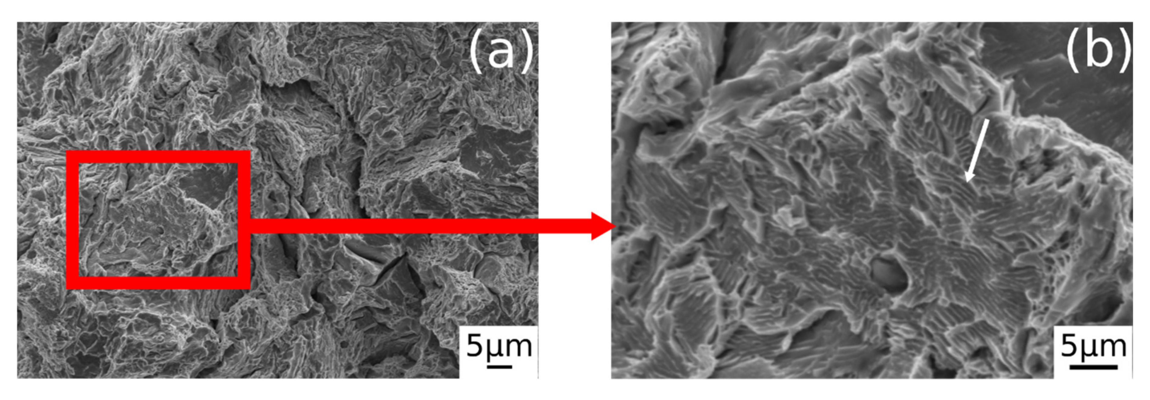
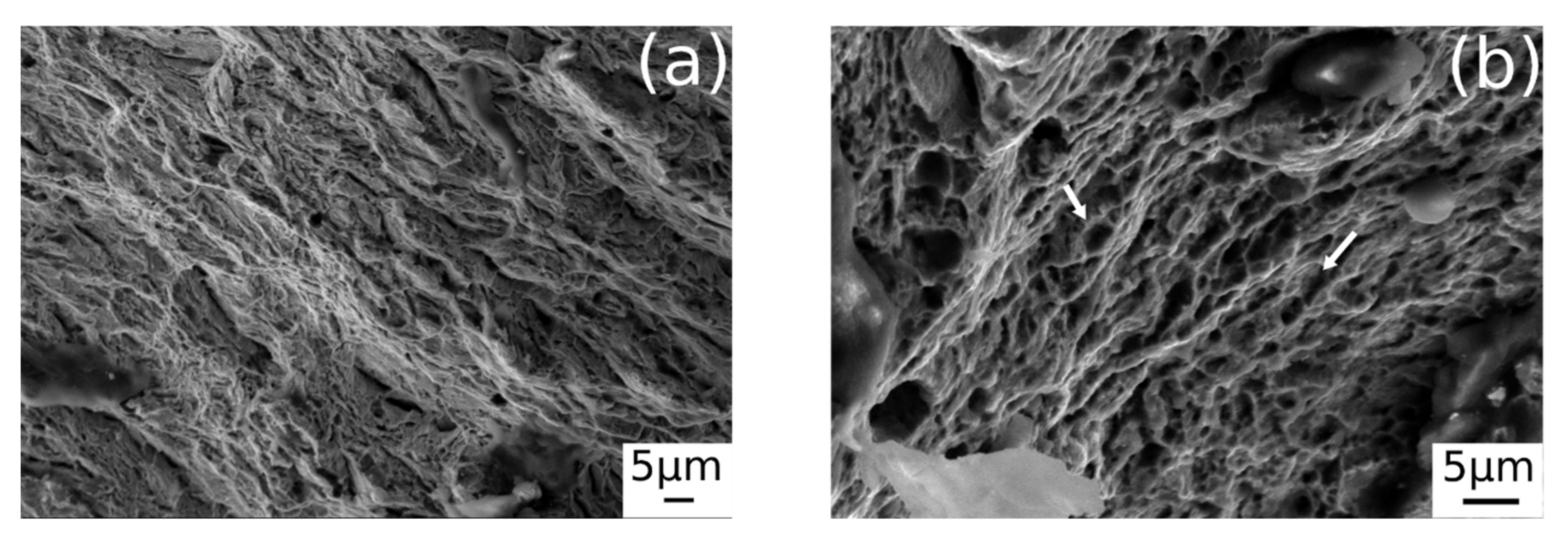
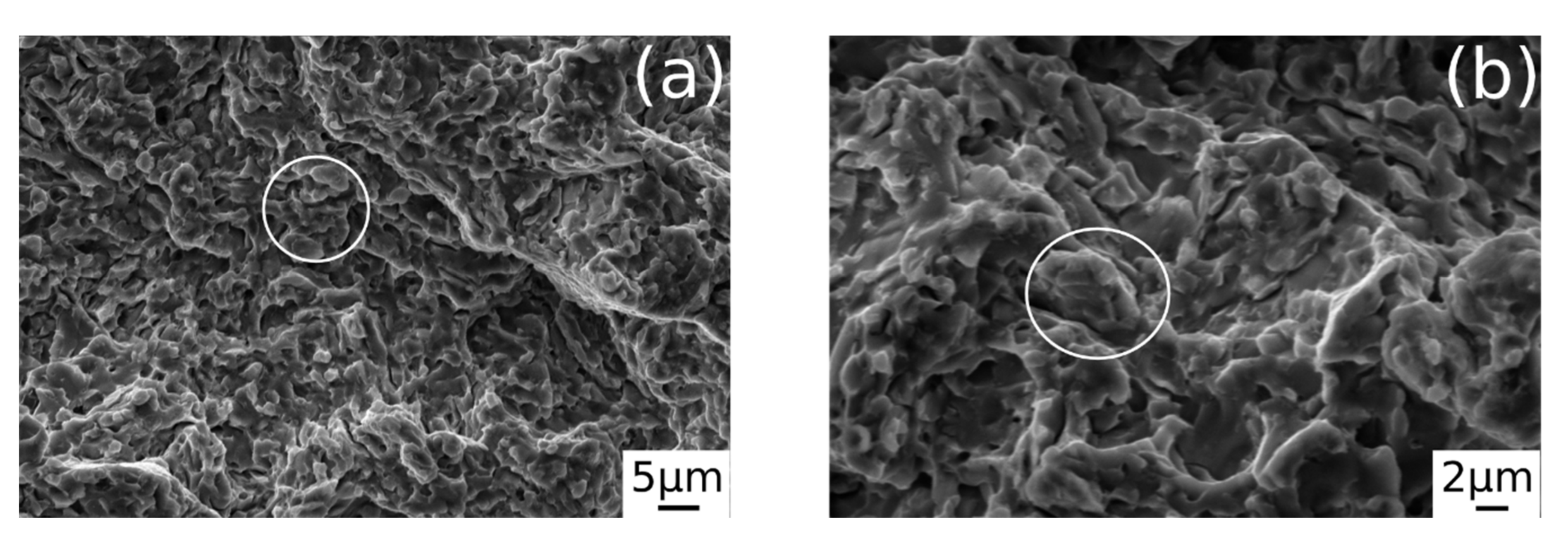
- Austempering treatment enhances material tensile strength (1650 MPa), in comparison with annealing and Q&T, which are characterized by lower tensile tests, 1130 and 1200 MPa respectively. However, the high amount of martensite, is responsible of low fracture strain (4.5%) and ductility, which is confirmed by the brittle fracture surface.
Author Contributions
Funding
Acknowledgments
Conflicts of Interest
References
- Mandal, D.; Ghosh, M.; Pal, J.; De, P.K.; Ghosh Chowdhury, S.; Das, S.K.; Das, G.; Ghosh, S. Effect of austempering treatment on microstructure and mechanical properties of high-Si steel. J. Mater. Sci. 2009, 44, 1069–1075. [Google Scholar] [CrossRef]
- Putatunda, S.K.; Singar, A.V.; Tackett, R.; Lawes, G. Development of a high strength high toughness ausferritic steel. Mater. Sci. Eng. A 2009, 513–514, 329–339. [Google Scholar] [CrossRef]
- Vuorinen, E.; Chen, X. In-situ high temperature X-ray studies on bainitic transformation of austempered silicon alloyed steels. Mater. Sci. Forum 2010, 638–642, 3086–3092. [Google Scholar] [CrossRef] [Green Version]
- Fonstein, N. Advanced High Strength Sheet Steels: Physical Metallurgy, Design, Processing, and Properties; Springer: Cham, Switzerland, 2015; ISBN 9783319191652. pp. 1–396. [Google Scholar]
- Edmonds, D.V.; Cochrane, R.C. Structure-property relationships in bainitic steels. Metall. Trans. A 1990, 21, 1527–1540. [Google Scholar] [CrossRef]
- Zhu, L.-J.; Di, W.U.; Zhao, X.-M. Effect of Silicon Content on Thermodynamics of Austenite Decomposition in C-Si-Mn TRIP Steels. J. Iron Steel Res. Int. 2006, 13, 57–60. [Google Scholar] [CrossRef]
- Zhu, L.J.; Wu, D.; Zhao, X.M. Effect of silicon addition on recrystallization and phase transformation behavior of high-strength hot-rolled trip steel. Acta Metall. Sin. Engl. Lett. 2008, 21, 163–168. [Google Scholar] [CrossRef]
- Matsumura, O.; Sakuma, Y. Retained Austenite in O.4C-Si-1.2Mn Steel Sheet Intercritically Heated and Austempered. ISIJ Int. 1992, 32, 4–10. [Google Scholar] [CrossRef] [Green Version]
- Xiong, X.C.; Chen, B.; Huang, M.X.; Wang, J.F.; Wang, L. The effect of morphology on the stability of retained austenite in a quenched and partitioned steel. Scr. Mater. 2013, 68, 321–324. [Google Scholar] [CrossRef]
- Timokhina, I.B.; Hodgson, P.D.; Pereloma, E.V. Effect of microstructure on the stability of retained austenite in {TRIP} steels. Metall. Mater. Trans. A 2004, 35, 2331–2340. [Google Scholar] [CrossRef] [Green Version]
- Pereloma, E.V.; Gazder, A.A.; Timokhina, I.B. Addressing retained austenite stability in advanced high strength steels. Mater. Sci. Forum 2013, 738–739, 212–216. [Google Scholar] [CrossRef] [Green Version]
- Blondé, R.; Jimenez-Melero, E.; Zhao, L.; Wright, J.P.; Brück, E.; Van Der Zwaag, S.; Van Dijk, N.H. High-energy X-ray diffraction study on the temperature-dependent mechanical stability of retained austenite in low-alloyed TRIP steels. Acta Mater. 2012, 60, 565–577. [Google Scholar] [CrossRef]
- Yi, J.J.; Kim, I.S.; Choi, H.S. Austenitization during intercritical annealing of an Fe-C-Si-Mn dual-phase steel. Metall. Trans. A 1985, 16, 1237–1245. [Google Scholar] [CrossRef]
- Kang, S.; De Moor, E.; Speer, J.G. Retained Austenite Stabilization Through Solute Partitioning During Intercritical Annealing in C-, Mn-, Al-, Si-, and Cr-Alloyed Steels. Metall. Mater. Trans. A Phys. Metall. Mater. Sci. 2015, 46, 1005–1011. [Google Scholar] [CrossRef]
- Samajdar, I.; Girault, E.; Verlinden, B.; Aernoudt, E.; Van Humbeeck, J. Transformations during intercritical annealing of a TRIP-assisted steel. ISIJ Int. 1998, 38, 998–1006. [Google Scholar] [CrossRef]
- Erişir, E.; Bilir, O.G. Effect of Intercritical Annealing Temperature on Martensite and Bainite Start Temperatures After Partial Austenitization. Jom 2016, 68, 203–209. [Google Scholar] [CrossRef]
- Faral, O. Influence of Continuous Annealing Conditions on Dual-Phase and TRIP Steels for Automotive Application. In Proceedings of the 41st Mechanical Working and Steel Processing Conference, Baltimore, MD, USA, 24–27 October 1999; pp. 253–264. [Google Scholar]
- Emadoddin, E.; Akbarzadeh, A.; Daneshi, G. Effect of intercritical annealing on retained austenite characterization in textured TRIP-assisted steel sheet. Mater. Charact. 2006, 57, 408–413. [Google Scholar] [CrossRef]
- Di Schino, A.; Di Nunzio, P.E. Metallurgical aspects related to contact fatigue phenomena in steels for back-up rolls. Acta Metall. Slovaca 2017, 23, 62–71. [Google Scholar] [CrossRef] [Green Version]
- Di Schino, A.; di Nunzio, P.E.; Lopez Turconi, G. Microstructure Evolution during Tempering of Martensite in a Medium-C Steel. Mater. Sci. Forum 2007, 558–559, 1435–1441. [Google Scholar] [CrossRef]
- De Oliveira, P.G.B.; Mariani, F.E.; Casteletti, L.C.; Itman Filho, A.; Neto, A.L.; Totten, G.E. Boro-Austempering Treatment of High-Strength Bainitic Steels. J. Mater. Eng. Perform. 2020, 29, 3486–3493. [Google Scholar] [CrossRef]
- Pashangeh, S.; Somani, M.; Banadkouki, S.S.G. Microstructural evolution in a high-silicon medium carbon steel following quenching and isothermal holding above and below the Ms temperature. J. Mater. Res. Technol. 2020, 9, 3438–3446. [Google Scholar]
- Di Schino, A.; Gaggiotti, M.; Testani, C. Heat Treatment Effect on Microstructure Evolution in a 7% Cr Steel for Forging. Metals 2020, 10, 808. [Google Scholar] [CrossRef]
- Han, J.; Lee, S.J.; Jung, J.G.; Lee, Y.K. The effects of the initial martensite microstructure on the microstructure and tensile properties of intercritically annealed Fe-9Mn-0.05C steel. Acta Mater. 2014, 78, 369–377. [Google Scholar] [CrossRef]
- Kim, S.I.; Jin, Y.H.; Kwak, J.N. Influence of Cooling Process after Hot Rolling on Mechanical Properties of Cold Rolled TRIP Steel. In Proceedings of the Materials Science & Technology 2008 Conference and Exhibition (MS&T Partner Societies), Pittsburgh, PA, USA, 5–9 October 2008; pp. 1784–1802. [Google Scholar]
- Pezzato, L.; Gennari, C.; Chukin, D.; Toldo, M.; Sella, F.; Toniolo, M.; Zambon, A.; Brunelli, K.; Dabalà, M. Study of the effect of multiple tempering on the impact toughness of forged s690 structural steel. Metals 2020, 10, 507. [Google Scholar] [CrossRef] [Green Version]
- Spezzapria, M.; Settimi, A.G.; Pezzato, L.; Novella, M.F.; Forzan, M.; Dughiero, F.; Bruschi, S.; Ghiotti, A.; Brunelli, K.; Dabalà, M. Effect of Prior Microstructure and Heating Rate on the Austenitization Kinetics of 39NiCrMo3 Steel. Steel Res. Int. 2017, 88, 1600267. [Google Scholar] [CrossRef]
- Gündüz, S.; Çapar, A. Influence of forging and cooling rate on microstructure and properties of medium carbon microalloy forging steel. J. Mater. Sci. 2006, 41, 561–564. [Google Scholar] [CrossRef]
- Babu, S.S.; Bhadeshia, H.K.D.H. A direct study of grain boundary allotriomorphic ferrite crystallography. Mater. Sci. Eng. A 1991, 142, 209–219. [Google Scholar] [CrossRef]
- Xu, P.; Bai, B.; Yin, F.; Fang, H.; Nagai, K. Microstructure control and wear resistance of grain boundary allotriomorphic ferrite/granular bainite duplex steel. Mater. Sci. Eng. A 2004, 385, 65–73. [Google Scholar] [CrossRef]
- Ahmad, E.; Manzoor, T.; Ziai, M.M.A.; Hussain, N. Effect of martensite morphology on tensile deformation of dual-phase steel. J. Mater. Eng. Perform. 2012, 21, 382–387. [Google Scholar] [CrossRef]
- Luo, Q. A new XRD method to quantify plate and lath martensites of hardened medium-carbon steel. J. Mater. Eng. Perform. 2016, 25, 2170–2179. [Google Scholar] [CrossRef] [Green Version]
- Mirnik, M.; Strohal, P.; Wrischer, M.; TeŽak, B. Elektronenmikroskopische Untersuchung der Silberjodidfällung. Kolloid Z. 1958, 160, 146–156. [Google Scholar] [CrossRef]
- Yescas, M.A.; Bhadeshia, H.K.D.H. Model for the maximum fraction of retained austenite in austempered ductile cast iron. Mater. Sci. Eng. A 2002, 333, 60–66. [Google Scholar] [CrossRef]
- Podder, A.S.; Bhadeshia, H.K.D.H. Thermal Stability of Austenite Retained in Bainitic Steels. Mater. Sci. Eng. A 2010, 527, 2121–2128. [Google Scholar] [CrossRef] [Green Version]
- Sherif, M.Y.; Mateo, C.G.; Sourmail, T.; Bhadeshia, H.K.D.H. Stability of retained austenite in TRIP-assisted steels. Mater. Sci. Technol. 2004, 20, 319–322. [Google Scholar] [CrossRef] [Green Version]
- Ryu, J.H.; Kim, D.I.; Kim, H.S.; Bhadeshia, H.K.D.H.; Suh, D.W. Strain partitioning and mechanical stability of retained austenite. Scr. Mater. 2010, 63, 297–299. [Google Scholar] [CrossRef]
- Sugimoto, K.I.; Yu, B.; Mukai, Y.I.; Ikeda, S. Microstructure and formability of aluminum bearing TRIP-aided steels with annealed martensite matrix. ISIJ Int. 2005, 45, 1194–1200. [Google Scholar] [CrossRef] [Green Version]
- Reisner, G.; Werner, E.A.; Fischer, F.D. Micromechanical modeling of martensitic transformation in random microstructures. Int. J. Solids Struct. 1998, 35, 2457–2473. [Google Scholar] [CrossRef]
- Carter, C.B.; Williams, D.B. Transmission Electron Microscopy; Springer: Boston, MA, USA, 1996. [Google Scholar]
- Qian, L.; Zhou, Q.; Zhang, F.; Meng, J.; Zhang, M.; Tian, Y. Microstructure and mechanical properties of a low carbon carbide-free bainitic steel co-alloyed with Al and Si. Mater. Des. 2012, 39, 264–268. [Google Scholar] [CrossRef]
- Toribio, J.; González, B.; Matos, J.C.; Ayaso, F.J. Influence of microstructure on strength and ductility in fully pearlitic steels. Metals 2016, 6, 318. [Google Scholar] [CrossRef] [Green Version]
- Shi, W.; Li, L.; Yang, C.X.; Fu, R.; Wang, L.; Wollants, P. Strain-induced transformation of retained austenite in low-carbon low-silicon TRIP steel containing aluminum and vanadium. Mater. Sci. Eng. A 2006, 429, 247–251. [Google Scholar] [CrossRef]
- Bhadeshia, H.K.D.H.; Edmonds, D.V. The Distribution of Retained Austenite in MArtensite and the Influence of Inter-lath Crystallography. In Proceedings of the International Conference on Martensitic Transformations, Cambridge, MA, USA, 24–29 June 1979; pp. 28–33. [Google Scholar]
- Lee, Y.K. Empirical formula of isothermal bainite start temperature of steels. J. Mater. Sci. Lett. 2002, 21, 1253–1255. [Google Scholar] [CrossRef]
- Krauss, G. Steels: Processing, Structure, and Performance; ASM International: New York, NY, USA, 2005; ISBN 0871708175. [Google Scholar]


| C | Si | Mn | P | S | Cr | Ni | Cu | Mo | Ti | V | Al |
|---|---|---|---|---|---|---|---|---|---|---|---|
| 0.43 | 3.26 | 2.72 | 0.010 | 0.0082 | 0.043 | 0.074 | 0.060 | 0.022 | 0.0010 | 0.0051 | 0.105 |
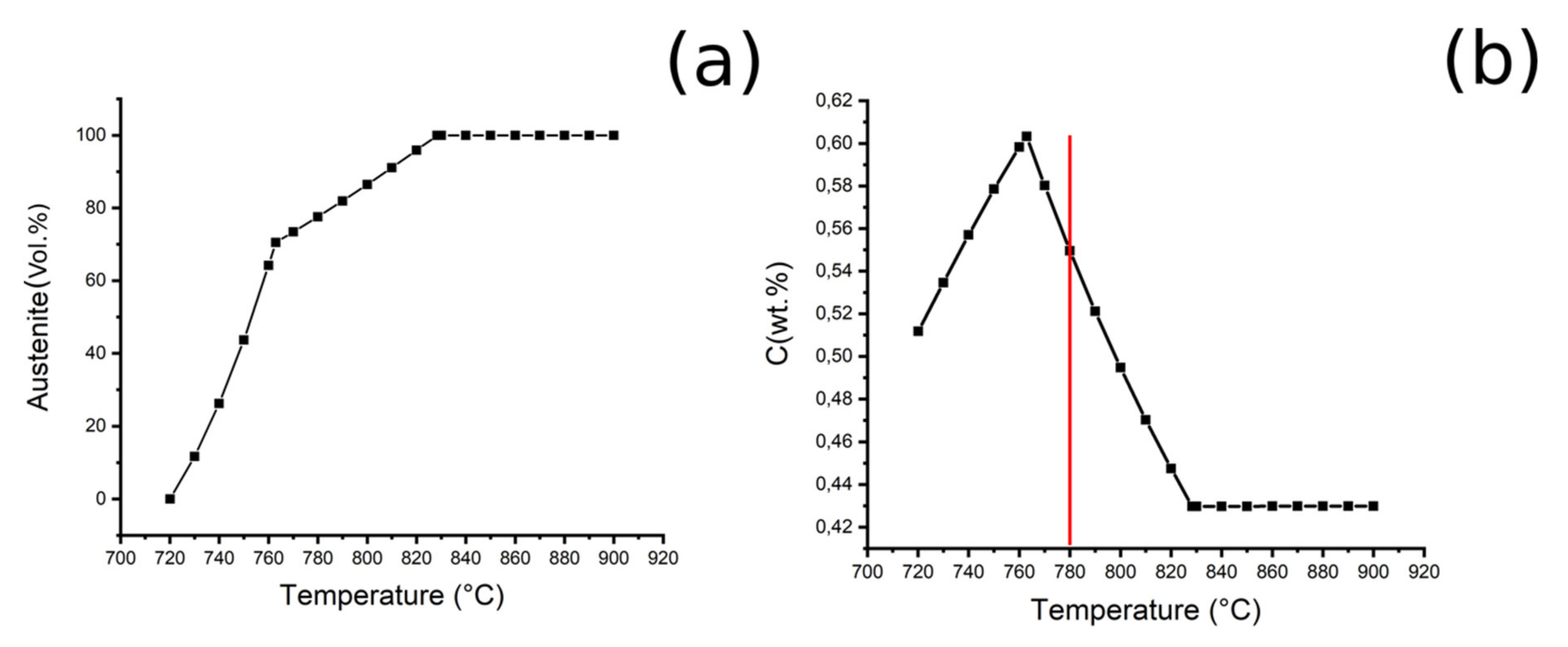
| Ac1 (°C) | Ac3 (°C) | Interctritical Annealing Temperature (°C) | Ferrite (wt.%) | Austenite (wt.%) | Cγ (wt.%) |
|---|---|---|---|---|---|
| ~763 | ~839 | ~780 | ~23 | ~76 | 0.55 |
| Retained Austenite (%) | Martensite (%) | Ferrite (%) |
|---|---|---|
| 14.9 | 40.5 | 44.6 |
| Treatment | Average (HV0.3) | St. Deviation |
|---|---|---|
| Annealed | 316 | 22 |
| Q&T | 364 | 29 |
| Austempering treatment | 426 | 19 |
| Material | Yield Strength (MPa) | Tensile Strength (MPa) | Fracture Strain (%) |
|---|---|---|---|
| Annealed | 730 | 1130 ± 5 | 20 ± 2 |
| Q&T | 760 | 1200 ± 5 | 16.5 ± 2 |
| Austempering treatment | 1250 | 1650 ± 5 | 4.5 ± 0.5 |
Publisher’s Note: MDPI stays neutral with regard to jurisdictional claims in published maps and institutional affiliations. |
© 2020 by the authors. Licensee MDPI, Basel, Switzerland. This article is an open access article distributed under the terms and conditions of the Creative Commons Attribution (CC BY) license (http://creativecommons.org/licenses/by/4.0/).
Share and Cite
Franceschi, M.; Pezzato, L.; Gennari, C.; Fabrizi, A.; Polyakova, M.; Konstantinov, D.; Brunelli, K.; Dabalà, M. Effect of Intercritical Annealing and Austempering on the Microstructure and Mechanical Properties of a High Silicon Manganese Steel. Metals 2020, 10, 1448. https://0-doi-org.brum.beds.ac.uk/10.3390/met10111448
Franceschi M, Pezzato L, Gennari C, Fabrizi A, Polyakova M, Konstantinov D, Brunelli K, Dabalà M. Effect of Intercritical Annealing and Austempering on the Microstructure and Mechanical Properties of a High Silicon Manganese Steel. Metals. 2020; 10(11):1448. https://0-doi-org.brum.beds.ac.uk/10.3390/met10111448
Chicago/Turabian StyleFranceschi, Mattia, Luca Pezzato, Claudio Gennari, Alberto Fabrizi, Marina Polyakova, Dmitry Konstantinov, Katya Brunelli, and Manuele Dabalà. 2020. "Effect of Intercritical Annealing and Austempering on the Microstructure and Mechanical Properties of a High Silicon Manganese Steel" Metals 10, no. 11: 1448. https://0-doi-org.brum.beds.ac.uk/10.3390/met10111448