Article

Influence of Vacuum Heat Treatments on Microstructure and Mechanical Properties of M35 High Speed Steel

1
Department of Engineering, University of Ferrara, via Saragat 1, 44122 Ferrara, Italy
2
Department of Industrial Engineering, University of Bologna, viale del Risorgimento 4, 40139 Bologna, Italy
*
Author to whom correspondence should be addressed.
Submission received: 6 April 2020 / Revised: 2 May 2020 / Accepted: 11 May 2020 / Published: 15 May 2020
(This article belongs to the Special Issue Heat Treatment of Steels)

Abstract

:
Towards the end of the last century, vacuum heat treatment of high speed steels was increasingly used in the fabrication of precision cutting tools. This study investigates the influence of vacuum heat treatments at different pressures of quenching gas on the microstructure and mechanical properties of taps made of M35 high speed steel. Taps were characterized by optical microscopy, scanning electron microscopy with energy dispersive spectroscopy, X-ray diffraction, apparent grain size and Vickers hardness measurements, and scratch tests. Failure analysis after tapping tests was also performed to determine the main fracture mechanisms. For all taps, the results showed that microstructures and the values of characteristics of secondary carbides, retained austenite, apparent grain size and Vickers hardness were comparable to previously reported ones for vacuum heat treated high speed steels. For taps vacuum heat treated at six bar, the highest plane strain fracture toughness was due to a higher content of finer small secondary carbides. In contrast, the lowest plane strain fracture toughness of taps vacuum heat treated at eight bar may be due to an excessive amount of finer small secondary carbides, which may provide a preferential path for crack propagation. Finally, the predominant fracture mechanism of taps was quasi-cleavage.

1. Introduction

High speed steels (HSS) are a complex class of tool steels continuously improved for applications in the global cutting tool market as wear-resistant materials for drills, taps, milling cutters, broaches, slotting tool and hobs. These steels must withstand abrasive or adhesive wear and have sufficient hardness, toughness and ductility to prevent chipping, galling, cracking, etc. [1].
In the fabrication of precision cutting tools, heat treatment of HSS in a salt bath has been replaced by vacuum heat treatment with uniform high-pressure gas quenching, since this procedure avoids waste and the need for washing the heat treated tools. A typical vacuum heat treatment includes several pre-heat, high heat, quenching and tempering stages. The final microstructure consists of large primary carbides in a tempered martensite matrix, hardened by the precipitation of uniformly distributed secondary carbides [2]. Nevertheless, the vacuum heat treatment has its limitations, especially concerning the number of pre-heats and holding time at high heat. Moreover, steel suppliers recommend only general guidelines about the quench rate of many grades of HSS in vacuum heat treatment [3].
The role of microstructural features is well-known in enhancing the mechanical properties of steels [2,4,5]. Over the past few decades, many studies have been carried out on wear resistance and performance of high speed steels after vacuum heat treatment. The effects of different austenitizing and tempering temperatures were evaluated, and the microstructure was optimized for increasing fracture toughness, hardness, fatigue and wear resistance of the tool [6,7,8,9,10,11]. With respect to fracture toughness, several authors used circumferentially notched and fatigue pre-cracked tensile test specimens, according to previously published methods [12,13]. The advantage of such specimens is their radial symmetry, which makes them specifically suitable for studying the influence of the microstructure on fracture toughness of metals. Due to the radial symmetry of heat transfer during heat treatment, the microstructure forming along a circumferential area is completely uniform. Moreover, the fatigue pre-crack can be created before the heat treatment without detrimental effects on the crack tip blunting. However, this method is not only difficult to apply, but also time consuming and expensive [14]. The most common alternative method is the Vickers indentation fracture test, where the fracture toughness is determined through a Vickers probe and by expressions accounting for indentation load, Young’s modulus, hardness, residual stresses, plastic dissipation inside the material and the nature of cracks produced during indentation [15,16,17]. Recently, Sola et al. proposed a novel technique to measure the fracture toughness of tool steels by scratch test [18]. Generally, the scratch test consists of pulling a probe across the surface of the material under a controllable applied load. According to the authors, the failure mode (fracture or plastic yielding) depends on material properties and geometry of the scratching tool. It is therefore possible to link the forces acting on the scratch tip and on the tool geometry to the plane strain fracture toughness (KC) by an equation accounting for the tangential force necessary to move the indenter, the indenter tip width and the measured penetration depth [16].
The present study investigates microstructure and mechanical properties of taps made of M35 high speed steel and vacuum heat treated at increasing pressures of quenching gas for improving their fracture toughness and durability. For this purpose, the microstructure and plane strain fracture toughness of taps undergoing conventional vacuum heat treatment were characterized by optical microscopy (OM), scanning electron microscopy with energy dispersive spectroscopy (SEM/EDS), X-ray diffraction (XRD), apparent grain size and Vickers hardness measurements, and scratch tests. Tapping tests and failure analyses were also performed on the same taps to determine the main fracture mechanisms involved during normal operating conditions. Finally, a new set of taps was vacuum heat treated at increasing pressures of quenching gas, and the resulting microstructure and plane strain fracture toughness were evaluated by the above mentioned techniques.

2. Materials and Methods

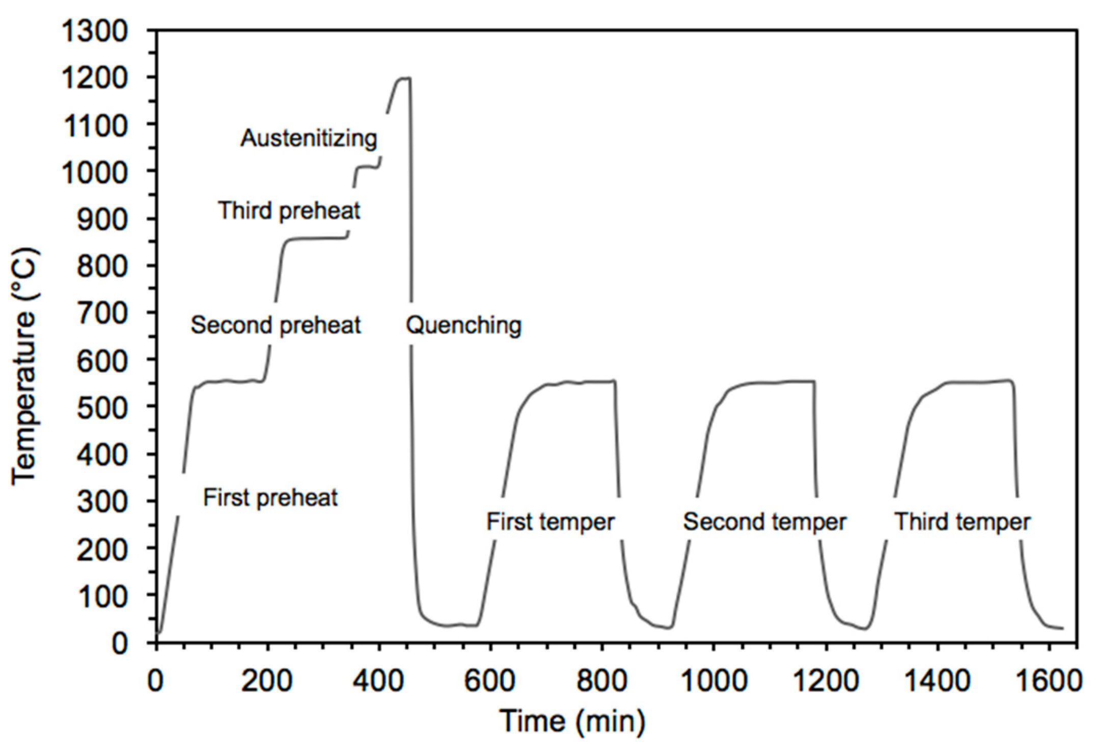
2.1. Chemical Composition and Conventional Heat Treatment of Taps

The material used in this investigation was commercially available M35 high speed steel with the following chemical composition (wt.%): 0.935% C, 0.362% Si, 0.233% Mn, 0.012% P, 0.001% S, 5.018% Co, 3.803% Cr, 4.643% Mo, 1.830% V, 6.613% W, balance Fe. The material was shaped in the form of cylindrical taps 10 mm in diameter and 100 mm in length.
The conventional heat treatment (indicated as CHT_5) of taps was carried out in a horizontal vacuum tube furnace with uniform high-pressure gas quenching, using nitrogen gas at a pressure of 5 bar and quenching speed of 10 °C/s. Quenching gas flew through nozzles located circumferentially on the walls of the furnace. After three preheat stages at 550, 850 and 1000 °C, the taps were heated at 2 °C/min to the austenitizing temperature of 1195 °C and maintained at this temperature for 10 min. Taps were then gas quenched from the austenitizing temperature to a temperature of 30 °C. Finally, triple tempering at 560 °C for 2 h were performed in the same furnace. All heat treatment parameters were selected on the basis of the recommendations of the steel supplier. The scheme in Figure 1 shows the CHT_5 treatment applied to the taps.

2.2. Material Characterization
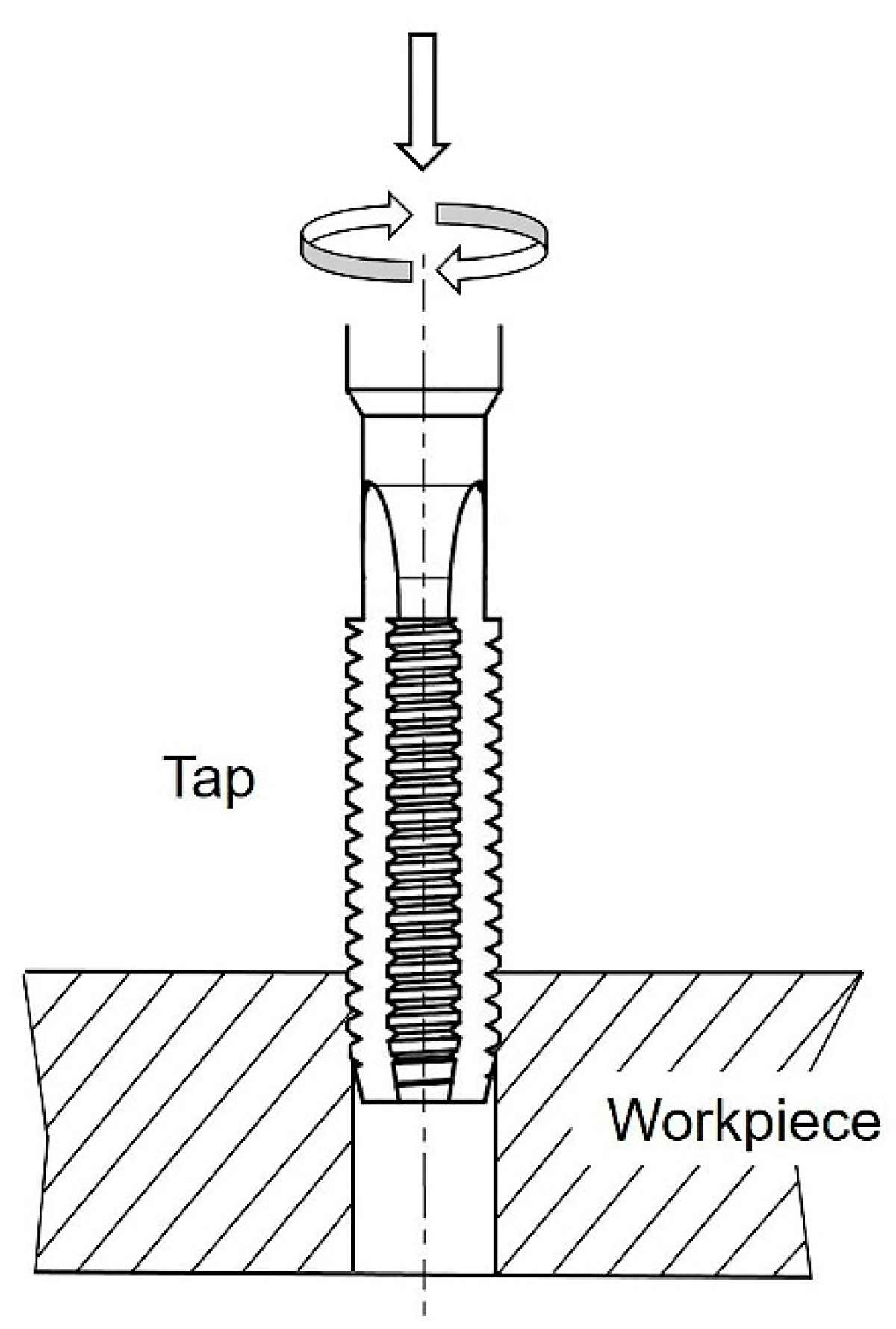
Material characterization was performed on taps pulled out of the horizontal vacuum furnace after quenching and tempering. To determine the microstructure of alloy, longitudinal sections (parallel to the metal surface) and cross-sections (perpendicular to the metal surface) of the taps were prepared, mounted in resin, polished and examined after chemical etching by Picral (4 g picric acid in 100 mL ethanol) through a Leica MEF4M optical microscope (Leica, Wetzlar, Germany) and a Zeiss EVO MA 15 (Zeiss, Oberkochen, Germany) scanning electron microscope (SEM), equipped with an Oxford X-Max 50 (Oxford Instruments, Abingdon-on-Thames, UK) energy dispersive microprobe for semi-quantitative analyses (EDS). The SEM micrographs were recorded in secondary electron imaging (SEI-SEM) and back-scattered electron (BSE-SEM) mode. The carbide particles visible in the matrix were classified as primary carbides (PCs: size > 5.0 μm) and secondary carbides (SCs: size ≤ 5.0 μm). The secondary carbides were further sub-classified as large secondary carbides (LSCs: 1.0 μm < size ≤ 5.0 μm) and small secondary carbides (SSCs: 0.1 μm ≤ size ≤ 1.0 μm) [19]. The micrographs of the cross-sections after tempering were processed by Leica Application Suite (LAS V4.12.0, Leica, Wetzlar, Germany) image analysis software to evaluate some characteristics of large and small secondary carbides, such as area fraction, population density and size, according to a previously described procedure [20]. A mean of 1000 secondary carbides was considered for each tap to achieve appropriate statistical reliability associated with these measurements.
On the cross-sections after tempering, the apparent grain size was determined in agreement with the EN ISO 643:2020 standard [21], whereas the type of carbide particles and retained austenite content (RA) were evaluated by X-ray diffraction (XRD) analyses of the bulk taps with a Philips X’PERT PW3050 diffractometer (Philips, Amsterdam, The Netherlands), using Cu-Kα radiations and diffracted beam monochromator, with an intensity scanner versus diffraction angle between 38° and 105° (0.01° step size, 2 s/step scanner velocity and 1.5 grid), a 40 kV voltage and a 40 mA filament current. The calculation of RA was performed according to the ASTM E975-13 standard [22].
The Vickers hardness measurements under 1000 gf load and 15 s loading time (HV1) were carried out in triplicate on the cross-sections by a Future-Tech FM-110 Vickers microindenter (Future-Tech Corp., Kawasaki, Japan). The Vickers hardness values were then converted in Rockwell C hardness values (HRC) in agreement with the ASTM E140-12B standard [23].
Finally, the fracture toughness was determined by scratch tests on the cross-sections after tempering and in agreement with a previously published method [18,24,25]. Prior to the tests, the surfaces of the samples were prepared according to a previously published procedure [26]. The scratch test produced a scratch in the material using a probe drawn across the sample under a constant vertical load and with constant speed. Compared to the standard fracture toughness tests, this technique provided the following advantages: (i) It was non-destructive; (ii) it did not require specific dimensions of the samples, nor an initial notch, pre-crack or fatigue crack; (iii) it allowed the sampling of the fracture properties at different locations in the material; (iv) it had a minimal cost and (v) could be performed on a limited supply of the material. The scratch tests were carried out by a Revetest Scratch Tester (CSM Instrument, Needham, MA, USA), using a 200 μm Rockwell C diamond probe, a scratching speed of 6 mm/min, an applied load of 100 N and a scratch length of 6 mm. In agreement with a previously published method [25], the plane strain fracture toughness KC was determined by the following equation,
K C = F t 2 w d ( w + 2 d )
where Ft is the tangential force necessary to move the indenter (measured by the equipment), w is the indenter tip width and d is the penetration depth. The penetration depth was directly calculated by the scratch tester. The equation was derived from previous studies on fracture mechanics framework [25,26].

2.3. Tapping Tests

Tapping tests were performed by a TH6563x63 (Shenyang Machine Tool Co., Ltd., Liaoning, China) horizontal tester machine. A grounded workpiece in 30CrMnTi steel, 700 × 500 × 48 mm3 in volume and with hardness equal to 210 HBW 2.5/187.5/30 was inserted and fixed inside the machine. Holes arranged in rows were made inside the workpiece. Taps were then rotated and moved into holes with a cutting speed of 7.5 m/min. A cutting fluid based on an emulsion of mineral oil at 5% was applied at a rate of 5 L/min. The criterion for end of tap life was its catastrophic failure. A scheme of the tapping test is shown in Figure 2.

2.4. Failure Analysis

After tapping tests, fracture surfaces of taps were first observed by a Leica MZ6 (Leica) stereomicroscope. To identify the main fracture mechanisms, morphological observations were performed by the Zeiss EVO MA 15 (Zeiss) scanning electron microscope with the Oxford X-Max 50 (Oxford Instruments) energy dispersive microprobe. Metallographic analyses of properly polished cross-sections of the fracture surfaces were conducted after chemical etching by Picral under the Leica MEF4M optical microscope (Leica).

2.5. Vacuum Heat Treatments

A new set of taps with the same chemical composition of those in Section 2.1 was heat treated in the horizontal vacuum furnace according to the treatment schematized in Figure 1, but using nitrogen gas at pressures of 6 and 8 bar (indicated as CHT_6 and CHT_8, respectively). During each heat treatment, the material was characterized following the procedure described in Section 2.2.

3. Results

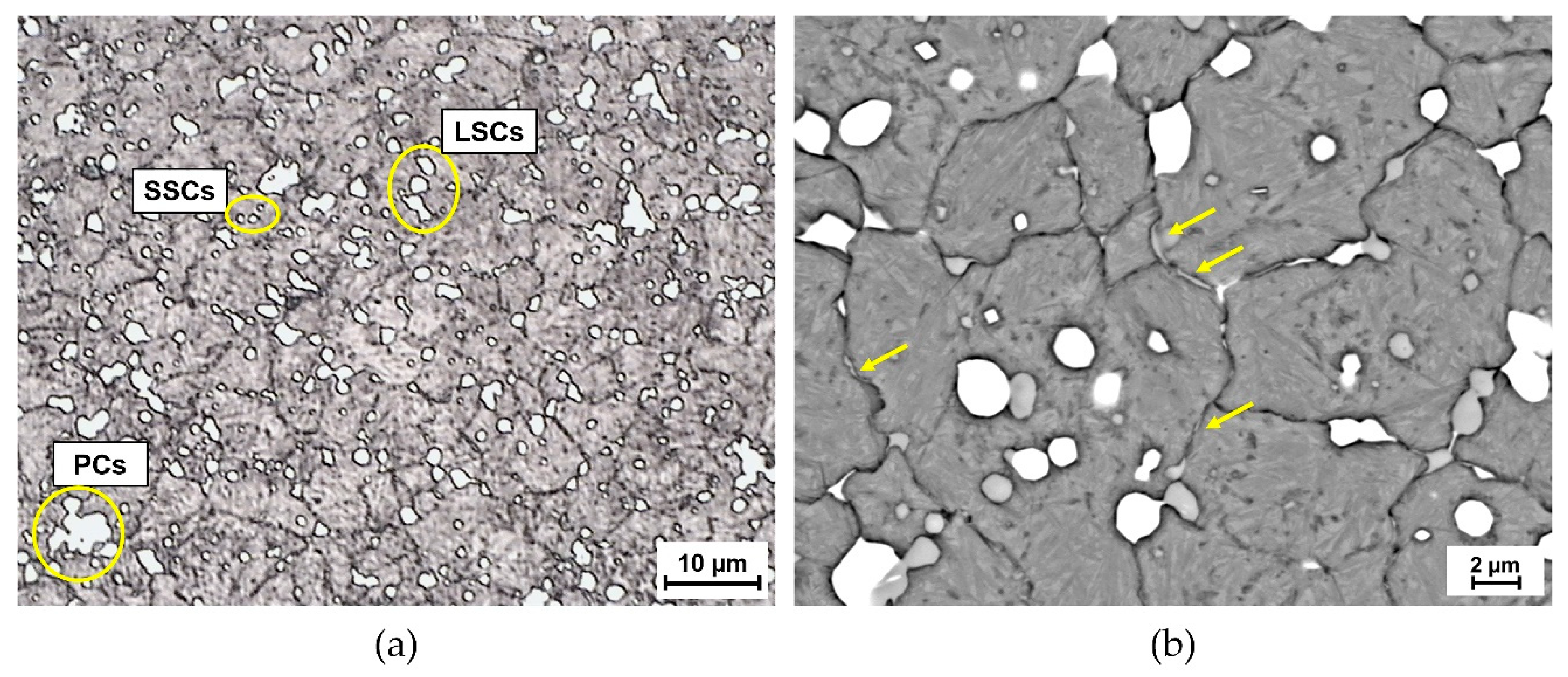
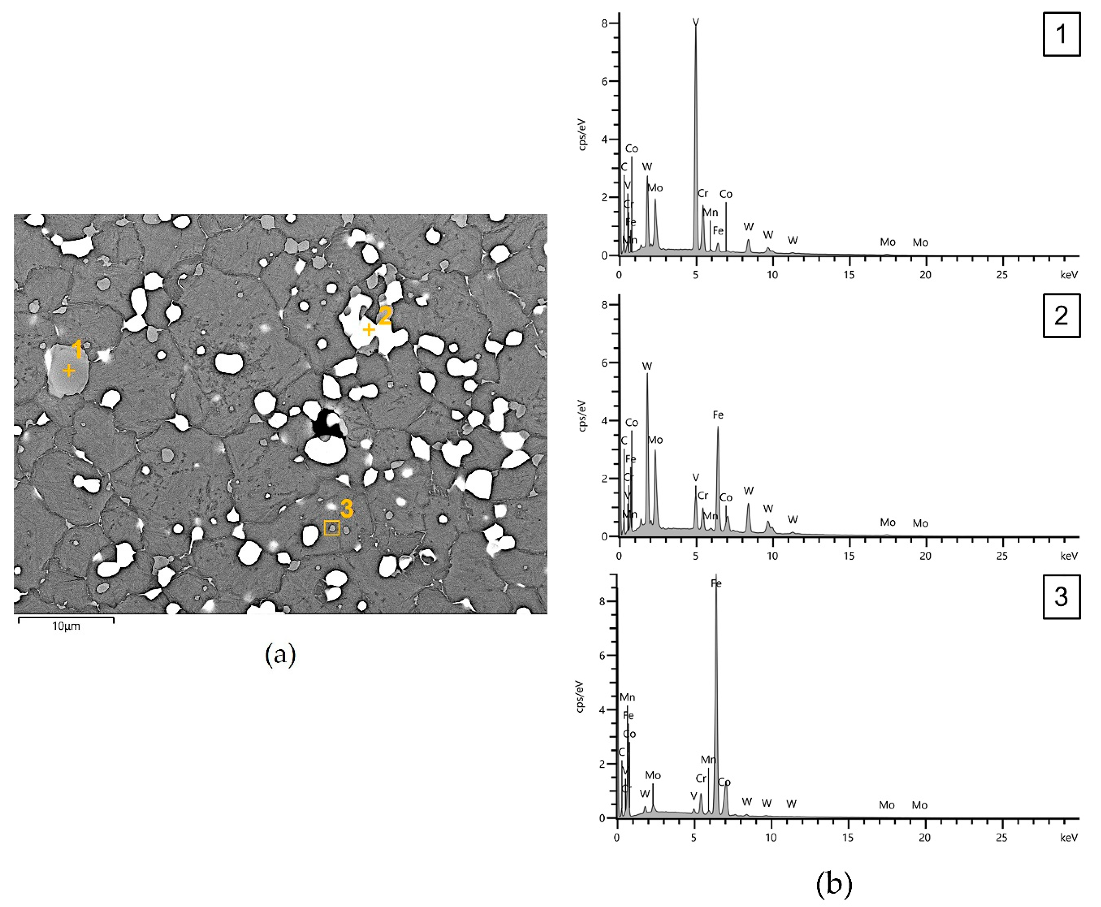
3.1. Microstructural Characterization and Hardness Variation

Optical and BSE-SEM micrographs of the microstructure observed on the cross-section of taps, after CHT_5 heat treatment, are shown in Figure 3. The microstructure exhibited a non-uniform distribution of large and dendritic-type primary carbides (marked by PCs), and a fairly uniform distribution of secondary carbides in a tempered martensite matrix, with retained austenite and resolved prior austenite grain boundaries. The two types of secondary carbides, classified according to their size, appeared either as well-defined white regions (marked by LSCs) or tiny white patches (marked by SSCs) (Figure 3a). In Figure 3b, a semi-continuous distribution of proeutectoid carbides was also visible along prior austenitic grain boundaries. The mean value of area fraction of large secondary carbides measured on taps cross-sections after CHT_5 heat treatment was 2.76 ± 0.23%, whereas those of population density and size were 4.0 ± 0.5 × 10³/mm2 and 2.78 ± 0.12 μm, respectively. The mean value of area fraction of small secondary carbides measured on the same regions was 2.53 ± 0.15%, while that of population density was 134 ± 4 × 10³/mm2. The mean value of size of small secondary carbides was 0.74 ± 0.08 μm.
Comparing the EDS semi-quantitative analyses of carbide particles (Figure 4), after quenching the primary carbides were rich in V or in W and Mo (spectra 1 and 2 in Figure 4), and changed only marginally their chemical composition after triple tempering at 560 °C. After quenching, secondary carbides and proeutectoid carbides were rich in Fe and poor in Cr, and maintained their chemical composition until the end of the heat treatment (spectrum 3 in Figure 4). Nevertheless, the EDS results proved that during tempering there was a precipitation of new Cr-rich secondary carbides. The XRD diffractograms recorded on the bulk taps after CHT_5 heat treatment revealed the presence of martensite (indexed as ferrite, since the resolution of the diffractometer was not sufficient to resolve the tetragonality of martensite), alloyed cementite (indexed as Fe3C), MC, M6C, M7C3 and RA (Figure 5). The mean value of RA in the matrix measured by XRD was 12.4 ± 0.5%.
The mean value of apparent grain size measured on tap cross-sections after CHT_5 heat treatment was 2.6 ± 0.1 μm (G14, according to the EN ISO 643:2020 standard), whereas that of plane strain fracture toughness, calculated by Equation (1), was 31 ± 5 MPa·m1/2. After quenching, the mean value of Vickers hardness measured on the same regions was 914 HV1 (corresponding to 67 HRC). Triple tempering at 560 °C resulted in Vickers hardness of 892 HV1, corresponding to 66 HRC.

3.2. Failure Analysis after Tapping Tests

After tapping tests, the stereomicroscopy images of the fracture surfaces of taps had a smooth and flat appearance, typical of brittle materials. At higher magnification, the SEI-SEM analyses revealed that the morphology of the fracture surfaces (Figure 6a) was characterized by two features: classical cleavage fracture of primary carbides (marked as C in Figure 6b) and quasi-cleavage fracture of the matrix (marked as the yellow rectangle QC in Figure 6b). In the first case, cracking of primary carbides was visible, and microcracks occurred at the interface between the primary carbide and the matrix. The EDS semi-quantitative analyses on the cleavage regions of the fracture surfaces confirmed that these regions corresponded to primary carbides. In the second case, a large number of microvoids were formed by decohesion of secondary carbides (yellow arrows in Figure 6c). No cracking of secondary carbides was detected. The optical micrograph of the fracture surfaces observed on the cross-sections of taps is shown in Figure 6d. These surfaces were mostly irregular. Fractures were deflected and partially surrounded the numerous secondary carbides detected close to the fracture surfaces, also suggesting that these carbide particles provided a preferential path for crack propagation.

3.3. Influence of Vacuum Heat Treatments on Microstructure and Fracture Toughness

Optical and scanning electron micrographs of the microstructure observed on the cross-sections of taps after CHT_6 and CHT_8 heat treatments (Figure 7a,c, respectively) were similar to those after CHT_5 (Figure 3a), but the extent of the semi-continuous distribution of proeutectoid carbides along prior austenitic grain boundaries decreased with increasing pressure of quenching gas (Figure 7b,d). During CHT_6 and CHT_8 heat treatments, primary and secondary carbides, detected by EDS and XRD, were unchanged with respect to those observed after CHT_5.
The characteristics of large and small secondary carbides at increasing pressure of quenching gas are shown in Figure 8a–c. The mean values of area fraction (Figure 8a) and population density (Figure 8b) of large and small secondary carbides progressively increased with increasing pressure of quenching gas. The mean value of area fraction of large secondary carbides increased up to the final value of 3.21 ± 0.19% (corresponding to an overall increase of about 16%), while that of small secondary carbides reached the final value of 3.49 ± 0.17% (corresponding to an overall increase of about 38%). The mean value of population density of large secondary carbides raised up to the final value of 9.0 ± 0.3 × 10³/mm2 (corresponding to an overall increase of about 125%), whereas that of small secondary carbides reached the final value of 167 ± 3 × 10³/mm2 (corresponding to an overall increase of about 25%). Conversely, the mean value of size of the same carbide particles was reduced with an increase in pressure of quenching gas (Figure 8c). The mean value of size of large secondary carbides decreased up to the final value of 2.17 ± 0.18 μm (corresponding to an overall decrease of about 22%), while that of small secondary carbides reached the final value of 0.58 ± 0.07% (corresponding to an overall decrease of about 21%).
The mean values of retained austenite, apparent grain size, plane strain fracture toughness and Vickers hardness of taps after the different heat treatments are reported in Table 1. The mean value of RA decreased with increasing pressure of quenching gas, reaching the final value of 10.8 ± 0.4% in taps undergoing the CHT_8 heat treatment. Irrespective of the type of heat treatment, there were almost no changes in mean apparent grain size, which ranged from 2.6 to 2.7 μm (G14, according to the EN ISO 643:2020 standard). The mean plane strain fracture toughness of taps initially increased up to 32 ± 6 MPa·m1/2 with increasing pressure of quenching gas, but then decreased with a further increase in the same parameter, reaching a minimum value of 26 ± 4 MPa·m1/2. Concerning Vickers hardness, the mean values ranged from 892 ± 11 (corresponding to 66 HRC) to 906 ± 4 (corresponding to 67 HRC) with varying pressure of quenching gas.
The relationships between plane strain fracture toughness and the characteristics of small secondary carbides are shown in Figure 9. Considering the CHT_5 and CHT_6 heat treatments, plane strain fracture toughness increased with increasing area fraction (Figure 9a) and population density (Figure 9b), but increased with decreasing of the size of small secondary carbides (Figure 9c). On the contrary, for taps undergoing the CHT_8 heat treatment, the higher area fraction and population density and the smaller size of small secondary carbides resulted in the lowest plane strain fracture toughness.

4. Discussion

The microstructure and mechanical properties of taps made of M35 high speed steel and vacuum heat treated at increasing pressures of quenching gas were studied for improving their fracture toughness and durability. The extensive metallographic investigation of taps, vacuum heat treated with pressure of quenching gas of five bar, shows a microstructure similar to that of high speed steels [2]. After tempering, the microstructure consists of a non-uniform distribution of large and dendritic-type MC and M6C primary carbides and a fairly uniform distribution of alloyed cementite and M7C3 secondary carbides in a tempered martensite matrix. Previous research showed that the V-rich MC primary carbides are known to be the hardest phase, main responsible for the wear resistance of HSS, whereas the W- and Mo-rich M6C primary carbides derive from the conversion of metastable M2C in more stable M6C during reheating for hot-forging or hot-rolling [27,28,29]. Concerning the Cr-rich M7C3 secondary carbides, studies on the effects of tempering conditions on secondary hardening of high speed steels proved that at tempering temperatures above 550 °C, these carbides gradually precipitate from the edge of the M6C primary carbides towards the interior [30]. After this process, M7C3 and M6C can coexist in the matrix, as supported by our SEM/EDS and XRD examinations. Based on the results of the image analysis, the area fraction, population density and size of large secondary carbides are between 2.53 and 2.99%, 3.5 and 4.5 × 10³/mm2, 2.66 and 2.90 μm, respectively. Considering the characteristics of small secondary carbides, area fraction is between 2.38 and 2.68%, while population density ranges from 130 to 138 × 103/mm2. The size is between 0.66 and 0.82 μm. All values of both large and small secondary carbides are comparable to those previously reported for vacuum heat treated high speed steels [18,31,32].
In the tempered martensite matrix, an average of 12.4% of retained austenite is detected, which represents good average value for commercial practice [33]. A certain amount of proeutectoid carbides is also visible along prior austenitic grain boundaries due to quench embrittlement [2]. This phenomenon involves the precipitation of carbide particles during cooling from austenitizing temperature, but when the material is still in the austenite field. The SEM/EDS analyses confirm that the precipitation occurs at the austenite grain boundaries since those regions are preferential sites for nucleation in terms of space and thermodynamic energy [2]. Overall, the presence of proeutectoid carbides does not affect the hardness of steels, but may favor crack propagation, and therefore, reduce the final fracture toughness [2]. In this study, not only the mean values of apparent grain size and Vickers hardness after tempering but also those of plane strain fracture toughness are comparable to those of high speed steels undergoing conventional vacuum heat treatments, despite the occurrence of the quench embrittlement phenomenon [9,33].
After tapping tests, failure analysis of vacuum heat treated taps by optical and scanning electron microscopy shows that, in normal operating conditions, the predominant fracture mechanism is quasi-cleavage [31,32]. Fracture initiates by cracking of primary carbides and cracking at the primary carbides/matrix interfaces, because these carbides are large and prone to fracture. Moreover, primary carbides are found in the interdendritic regions and such non-uniform distribution facilitates their cracking from the matrix at low-stress levels [20]. The nucleation of microvoids by decohesion of secondary carbides then occurs, followed by cleavage fracture. Unlike primary carbides, no cracking of secondary carbides is detected. Formation of microvoids by decohesion of secondary carbides is quite common in the fracture processes of tool steels [18,34,35,36]. The criteria for void nucleation is based on the dislocation pile-up model [31]. In detail, void nucleates when the local interfacial stresses, occurring on a carbide particle, reach a critical interfacial strength, which is a characteristic of the material.
Vacuum heat treatment of taps at pressures of quenching gas of six and eight bar to improve their fracture toughness and durability produces microstructures similar to those of taps vacuum heat treated at five bar, but with lower amounts of retained austenite and proeutectoid carbides along prior austenitic grain boundaries. An increase in the pressure of quenching gas also modifies the precipitation behavior of secondary carbides, as proved by the rise in their area fraction and population density, and by the decrease in size of large and small secondary carbides [31,32]. Slight differences are found in the mean apparent grain size and Vickers hardness of all taps.
With respect to plane strain fracture toughness, it is known that the microstructure has a great influence on this parameter [33]. In our taps, among all microstructural constituents primary carbides appear identical regardless of the type of heat treatment, since their characteristic are controlled only by the temperature and time of austenitization [32]. Accordingly, any variation of the measured plane strain fracture toughness is supposed to be due to alterations of the secondary carbides, and more specifically, the small secondary carbides. By comparing the plane strain fracture toughness of conventionally heat treated taps with that of taps vacuum heat treated at six bar, it was observed that the plane strain fracture toughness slightly increased with increasing area fraction and population density, but also with decreasing size of small secondary carbides. Based on the metallographic analyses by optical microscopy of our fracture surfaces, this may be due to the fact that small secondary carbides, more uniformly distributed, are able to deflect more effectively cracks propagation, leading to more energy absorption associated with cracking. Moreover, some authors also demonstrated that the precipitation of a higher amount of small secondary carbides reduced the contents of dissolved carbon and alloying elements in the matrix, thus raising its ductility and fracture toughness [31]. Nevertheless, taps vacuum heat treated at a pressure of quenching gas of eight bar showed the lowest plane strain fracture toughness, despite the highest area fraction and population density, and the smallest size of small secondary carbides. This is probably due to an excessive amount of finer small secondary carbides, which may reduce the plane strain fracture toughness of our high speed steel by providing a preferential path for crack propagation.

5. Conclusions

This study investigates the microstructure and mechanical properties of taps made of M35 high speed steel and vacuum heat treated at increasing pressures of quenching gas, in order to improve their fracture toughness and durability. Based on the results, the following conclusions can be drawn:
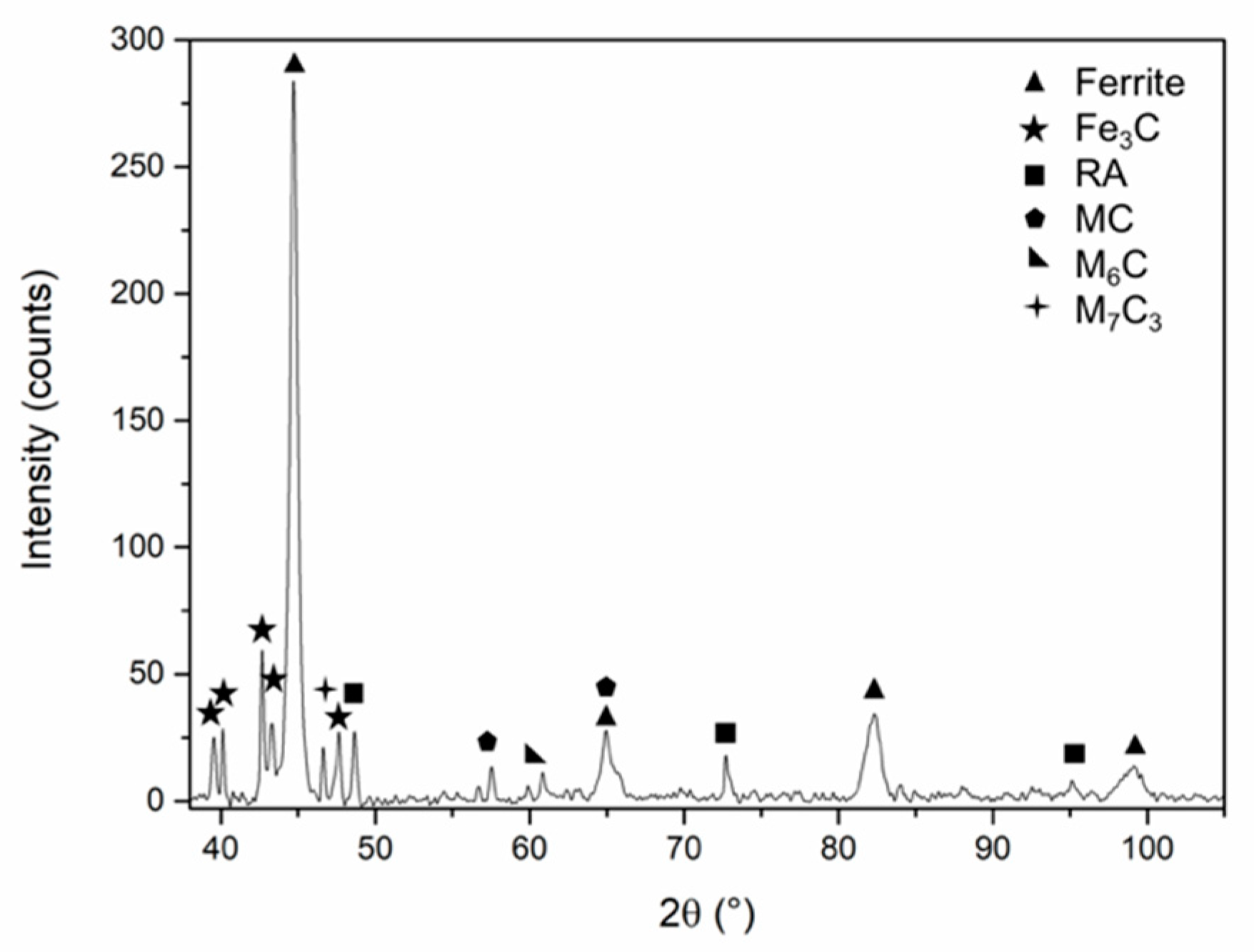
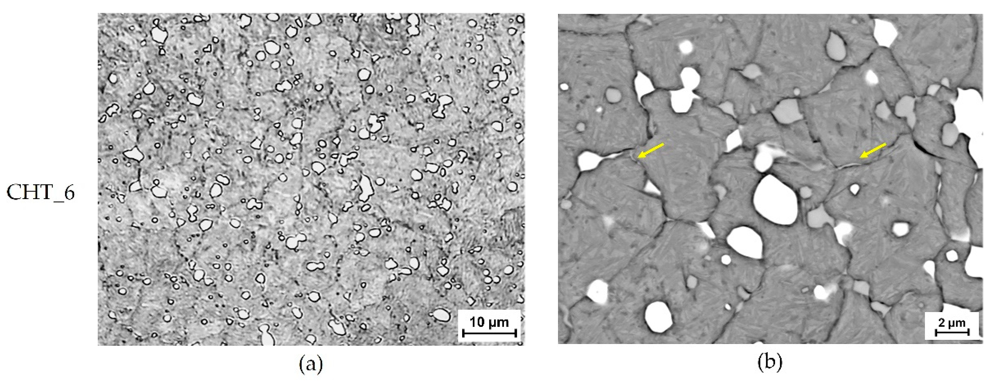
  • The microstructure of taps undergoing vacuum heat treatment at a pressure of quenching gas of five bar is similar to that of high speed steels. The microstructure mostly consists of primary carbides (MC and M6C), alloyed cementite and secondary carbides (M7C3) in a tempered martensite matrix, with retained austenite and proeutectoid carbides along prior austenite grain boundaries. All values of the characteristics of secondary carbides, as well as those of retained austenite, apparent grain size, Vickers hardness and plane strain fracture toughness are comparable to previously reported data for vacuum heat treated high speed steels;
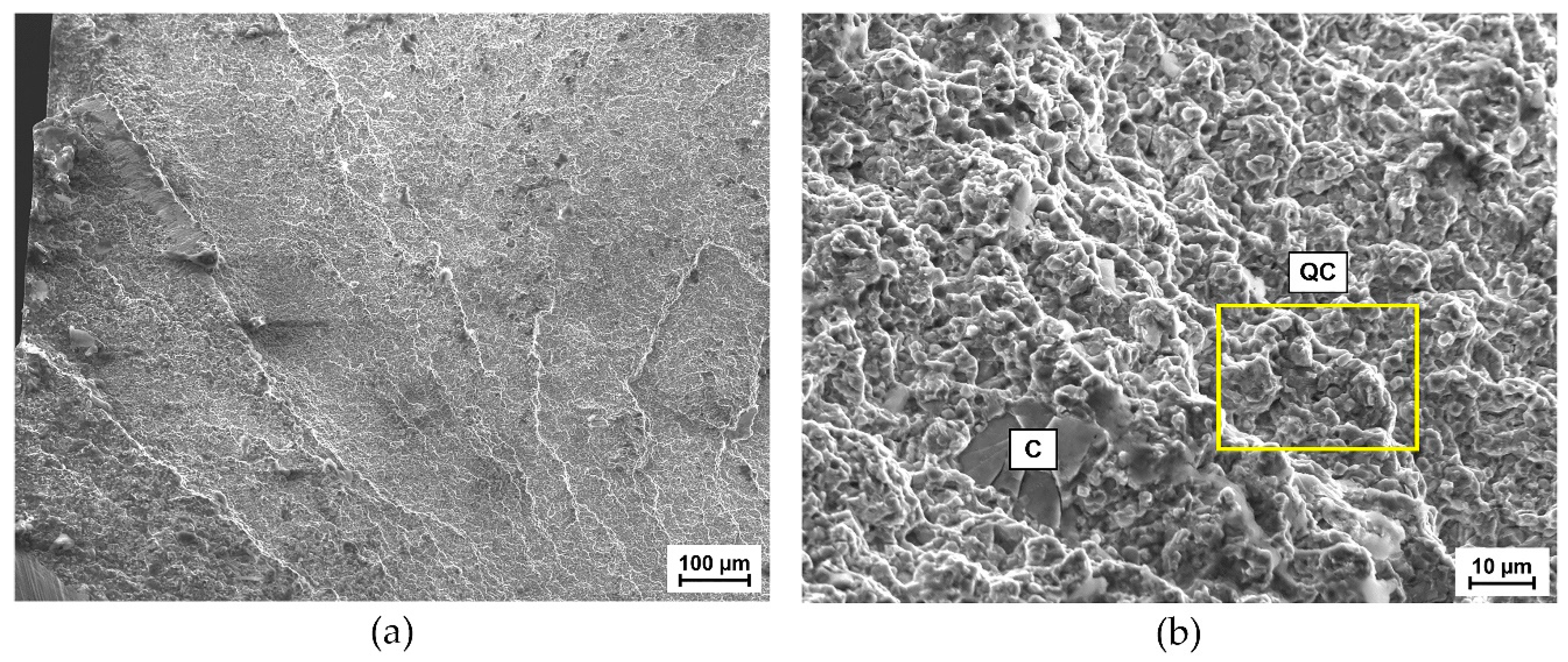
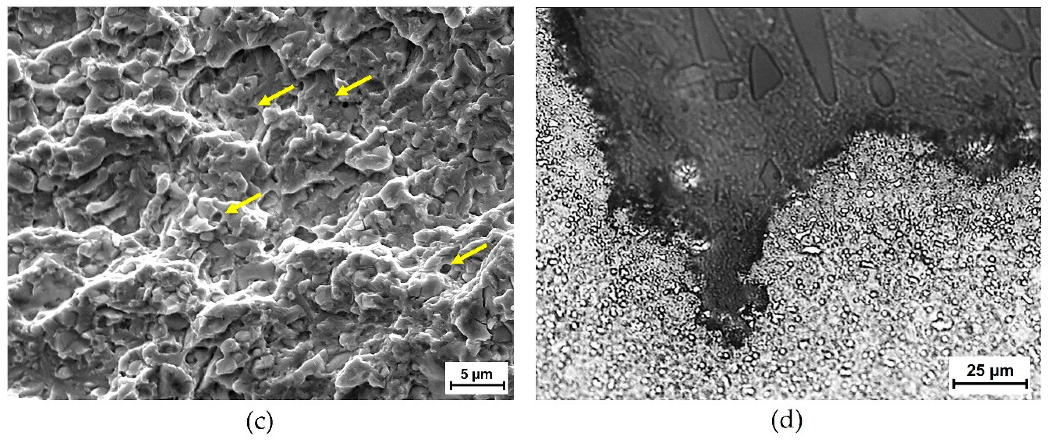
  • in normal operating conditions the predominant fracture mechanism of taps is quasi-cleavage. Fracture initiates by cracking of primary carbides at the primary carbides/matrix interfaces and by nucleation of microvoids by decohesion of secondary carbides, followed by cleavage fracture;
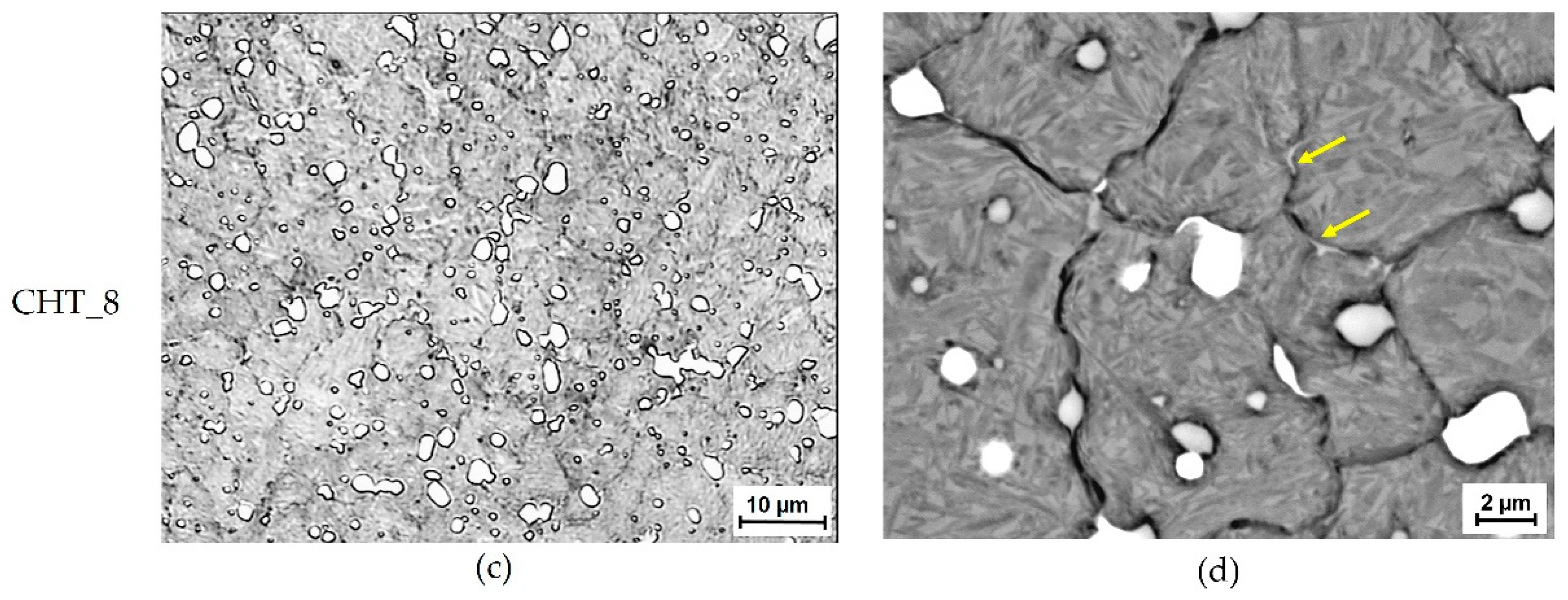
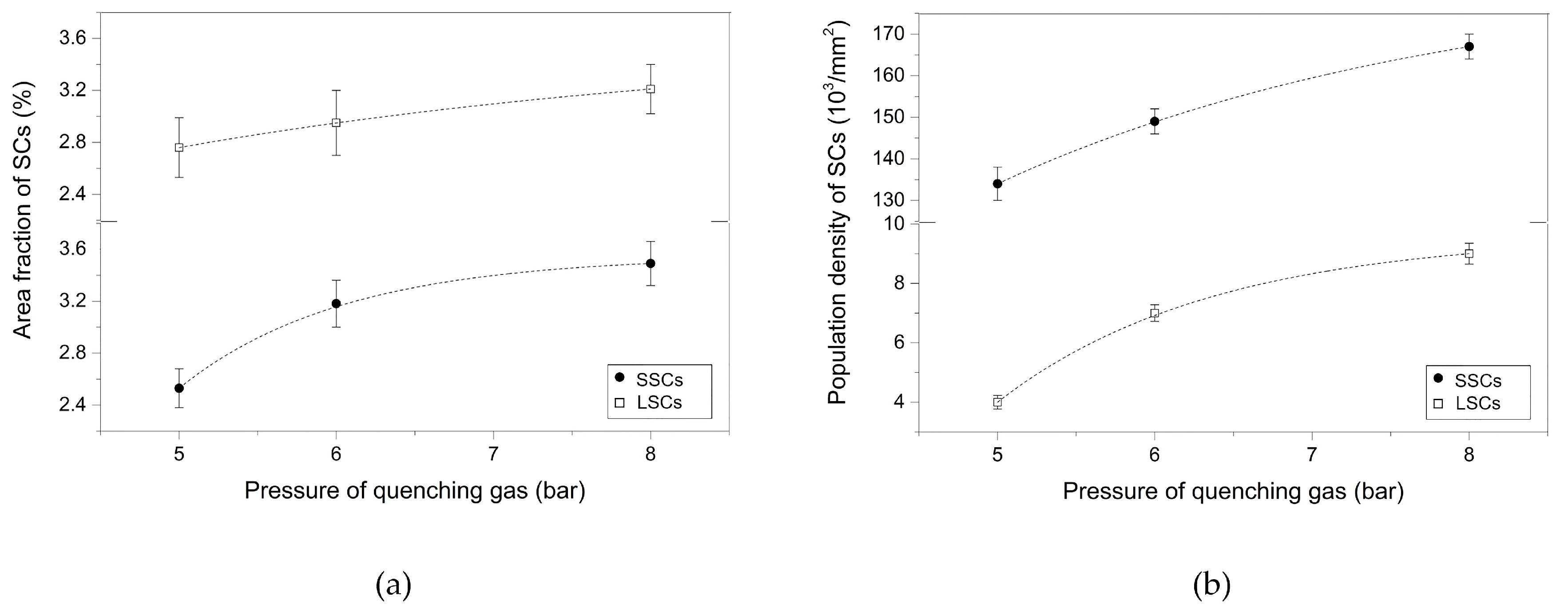
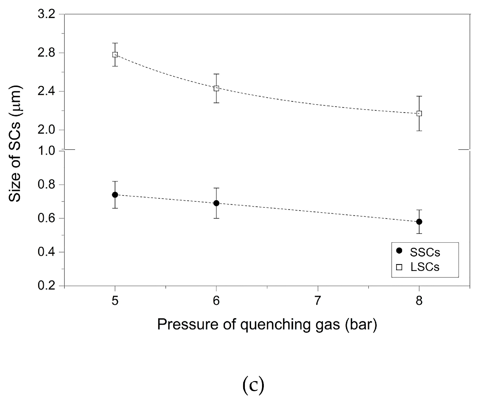
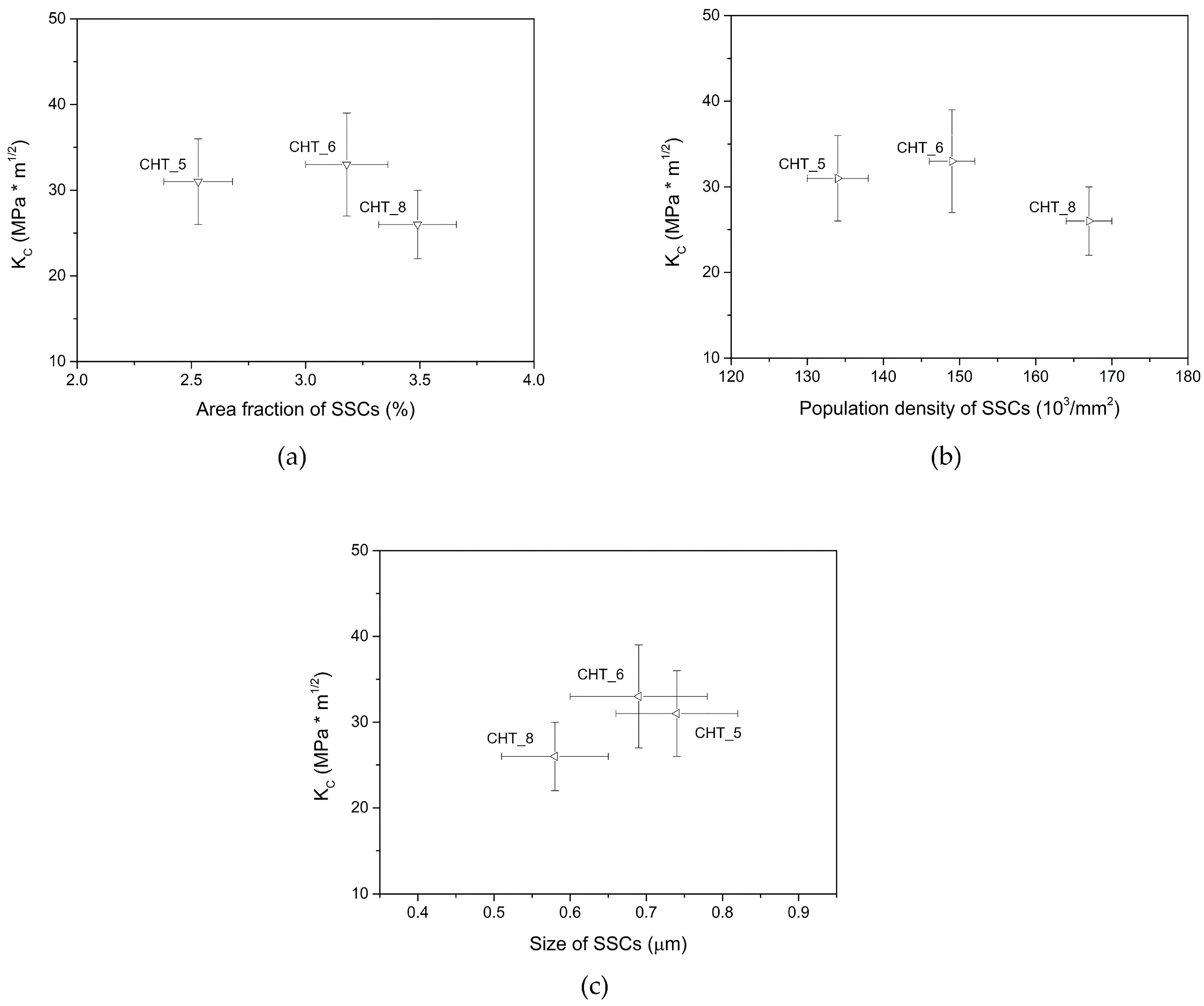
  • vacuum heat treatment of taps at pressures of quenching gas of six and eight bar produces microstructures similar to those of taps vacuum heat treated at a pressure of quenching gas of five bar, but with lower amounts of retained austenite and proeutectoid carbides along prior austenitic grain boundaries. An increase in pressure of quenching gas also modifies the precipitation behavior of secondary carbides, whereas slight differences are found in the mean apparent grain size and Vickers hardness of all taps. In relation to plane strain fracture toughness, taps vacuum heat treated at six bar shows the highest values of this parameter thanks to a higher content of finer small secondary carbides, which deflect crack propagation. Conversely, the lowest plane strain fracture toughness of taps vacuum heat treated at eight bar may be due to an excessive amount of finer small secondary carbides, which may provide a preferential path for crack propagation.

Author Contributions

In the frame of the present investigation, C.S. conceived the experiments and wrote the manuscript. A.F. contributed to data analyses and to the manuscript. R.S. and E.F. supported the experimental investigations. M.M. and G.L.G. supervised the experiments and aided the results discussion. All authors have read and agreed to the published version of the manuscript.

Funding

This research was funded by the Department of Engineering, University of Ferrara (Ferrara, Italy), grant number 2238/2010.

Acknowledgments

The authors would like to dedicate this study to the memory of Vincenzo Gabrielli, whose invaluable contribution to the experimental activity and whose guidance have been essential to achieve the present results. The authors also thank Milvia Chicca for help in revising the manuscript.

Conflicts of Interest

The authors declare no conflict of interest.

References

  1. Statharas, D.; Papageorgiou, D.; Sideris, J.; Medrea, C. Preliminary examination of the fracture surfaces of a cold working die. Int. J. Mater. Form. 2008, 1, 431–434. [Google Scholar] [CrossRef]
  2. Mesquita, R.A. High-speed steels. In Tool Steels: Properties and Performance, 1st ed.; CRC Press: Boca Raton, FL, USA, 2017; pp. 217–239. [Google Scholar]
  3. Rousseau, A.; Doyle, E.; McCulloch, D. Vacuum heat treatment of high speed steel cutting tools. Int. Heat Treat. Surf. Eng. 2013, 7, 110–114. [Google Scholar] [CrossRef]
  4. Di Schino, A.; Di Nunzio, P.E.; Lopez Turconi, G. Microstructure Evolution during Tempering of Martensite in a Medium-C Steel. Mater. Sci. Forum 2007, 558–559, 1435–1441. [Google Scholar] [CrossRef]
  5. Di Schino, A. Analysis of heat treatment effect on microstructural features evolution in a micro-alloyed martensitic steel. Acta Metall. Slovaca 2016, 22, 266–270. [Google Scholar] [CrossRef] [Green Version]
  6. Leskovšek, V.; Šuštaršič, B.; Jutriša, G. The influence of austenitizing and tempering temperature on the hardness and fracture toughness of hot-worked H11 tool steel. J. Mater. Process. Technol. 2006, 178, 328–334. [Google Scholar] [CrossRef]
  7. Podgornik, B.; Leskovšek, V. Microstructure and Origin of Hot-Work Tool Steel Fracture Toughness Deviation. Metall. Mater. Trans. A 2013, 44, 5694–5702. [Google Scholar] [CrossRef]
  8. Leskovšek, V.; Podgornik, B. Vacuum heat treatment, deep cryogenic treatment and simultaneous pulse plasma nitriding and tempering of P/M S390MC steel. Mater. Sci. Eng. A 2012, 531, 119–129. [Google Scholar] [CrossRef]
  9. Leskovšek, V.; Ule, B. Improved vacuum heat-treatment for fine-blanking tools from high-speed steel M2. J. Mater. Process. Technol. 1998, 82, 89–94. [Google Scholar] [CrossRef]
  10. Suchánek, J.; Kuklík, V. Influence of heat and thermochemical treatment on abrasion resistance of structural and tool steels. Wear 2009, 267, 2100–2108. [Google Scholar] [CrossRef]
  11. Podgornik, B.; Leskovšek, V.; Tehovnik, F.; Burja, J. Vacuum heat treatment optimization for improved load carrying capacity and wear properties of surface engineered hot work tool steel. Surf. Coat. Technol. 2015, 261, 253–261. [Google Scholar] [CrossRef]
  12. Ule, B.; Leskovšek, V.; Tuma, B. Estimation of plain strain fracture toughness of AISI M2 steel from precracked round-bar specimens. Eng. Fract. Mech. 2000, 65, 559–572. [Google Scholar] [CrossRef]
  13. Podgornik, B.; Leskovšek, V. Experimental Evaluation of Tool and High-Speed Steel Properties Using Multi-Functional KIc -Test Specimen. Steel Res. Int. 2013, 84, 1294–1301. [Google Scholar] [CrossRef]
  14. Leskovšek, V.; Ule, B.; Liščić, B. Relations between fracture toughness, hardness and microstructure of vacuum heat-treated high-speed steel. J. Mater. Process. Technol. 2002, 127, 298–308. [Google Scholar] [CrossRef]
  15. Quinn, G.D.; Bradt, R.C. On the Vickers Indentation Fracture Toughness Test. J. Am. Ceram. Soc. 2007, 90, 673–680. [Google Scholar] [CrossRef]
  16. Harding, D.S.; Oliver, W.C.; Pharr, G.M. Cracking During Nanoindentation and its Use in the Measurement of Fracture Toughness. MRS Online Proc. Libr. 1994, 356, 663. [Google Scholar] [CrossRef] [Green Version]
  17. Widjaja, S.; Yip, T.H.; Limarga, A.M. Measurement of creep-induced localized residual stress in soda-lime glass using nano-indentation technique. Mater. Sci. Eng. A 2001, 318, 211–215. [Google Scholar] [CrossRef]
  18. Sola, R.; Giovanardi, R.; Parigi, G.; Veronesi, P. A Novel Method for Fracture Toughness Evaluation of Tool Steels with Post-Tempering Cryogenic Treatment. Metals 2017, 7, 75. [Google Scholar] [CrossRef] [Green Version]
  19. Das, D.; Dutta, A.K.; Ray, K.K. On the refinement of carbide precipitates by cryotreatment in AISI D2 steel. Philos. Mag. 2009, 89, 55–76. [Google Scholar] [CrossRef]
  20. Fukaura, K.; Yokoyama, Y.; Yokoi, D.; Tsujii, N.; Ono, K. Fatigue of cold-work tool steels: Effect of heat treatment and carbide morphology on fatigue crack formation, life, and fracture surface observations. Metall. Mater. Trans. A Phys. Metall. Mater. Sci. 2004, 35, 1289–1300. [Google Scholar] [CrossRef]
  21. ISO. EN ISO 643: Steels—Micrographic Determination of the Apparent Grain Size; ISO International: Geneva, Switzerland, 2020. [Google Scholar]
  22. ASTM International. ASTM Standard E975-13: Standard Practice for X-Ray Determination of Retained Austenite in Steel with Near Random Crystallographic Orientation; ASTM International: West Conshohocken, PA, USA, 2013. [Google Scholar] [CrossRef]
  23. ASTM International. ASTM Standard E140-12B(2019)e1: Standard Hardness Conversion Tables for Metals Relationship Among Brinell Hardness, Vickers Hardness, Rockwell Hardness, Superficial Hardness, Knoop Hardness, Scleroscope Hardness, and Leeb Hardness; ASTM International: West Conshohocken, PA, USA, 2019. [Google Scholar] [CrossRef]
  24. Akono, A.-T.; Ulm, F.-J. Scratch test model for the determination of fracture toughness. Eng. Fract. Mech. 2011, 78, 334–342. [Google Scholar] [CrossRef]
  25. Akono, A.-T.; Ulm, F.-J. An improved technique for characterizing the fracture toughness via scratch test experiments. Wear 2014, 313, 117–124. [Google Scholar] [CrossRef]
  26. Akono, A.-T.; Randall, N.X.; Ulm, F.-J. Experimental determination of the fracture toughness via microscratch tests: Application to polymers, ceramics, and metals. J. Mater. Res. 2012, 27, 485–493. [Google Scholar] [CrossRef]
  27. Sackl, S.; Leitner, H.; Clemens, H.; Primig, S. On the evolution of secondary hardening carbides during continuous versus isothermal heat treatment of high speed steel HS 6-5-2. Mater. Charact. 2016, 120, 323–330. [Google Scholar] [CrossRef]
  28. Pan, F.; Wang, W.; Tang, A.; Wu, L.; Liu, T.; Cheng, R. Phase transformation refinement of coarse primary carbides in M2 high speed steel. Prog. Nat. Sci. Mater. Int. 2011, 21, 180–186. [Google Scholar] [CrossRef] [Green Version]
  29. Wieβner, M.; Leisch, M.; Emminger, H.; Kulmburg, A. Phase transformation study of a high speed steel powder by high temperature X-ray diffraction. Mater. Charact. 2008, 59, 937–943. [Google Scholar] [CrossRef]
  30. Liu, B.; Qin, T.; Xu, W.; Jia, C.; Wu, Q.; Chen, M.; Liu, Z. Effect of Tempering Conditions on Secondary Hardening of Carbides and Retained Austenite in Spray-Formed M42 High-Speed Steel. Materials 2019, 12, 3714. [Google Scholar] [CrossRef] [Green Version]
  31. Das, D.; Sarkar, R.; Dutta, A.K.; Ray, K.K. Influence of sub-zero treatments on fracture toughness of AISI D2 steel. Mater. Sci. Eng. A 2010, 528, 589–603. [Google Scholar] [CrossRef]
  32. Yan, X.G.; Li, D.Y. Effects of the sub-zero treatment condition on microstructure, mechanical behavior and wear resistance of W9Mo3Cr4V high speed steel. Wear 2013, 302, 854–862. [Google Scholar] [CrossRef]
  33. Roberts, G.; Krauss, G.; Kennedy, R. High speed steels. In Tool Steels, 5th ed.; ASM International: Materials Park, OH, USA, 1998; pp. 251–290. [Google Scholar]
  34. Imbert, C.A.C.; McQueen, H.J. Flow curves up to peak strength of hot deformed D2 and W1 tool steels. Mater. Sci. Technol. 2000, 16, 524–531. [Google Scholar] [CrossRef]
  35. Johnson, A.R. Fracture toughness of AISI M2 and AISI M7 high-speed steels. Metall. Trans. A 1977, 8, 891–897. [Google Scholar] [CrossRef]
  36. Sola, R.; Veronesi, P.; Giovanardi, R.; Merlin, M.; Garagnani, G.L.; Soffritti, C.; Morri, A.; Parigi, G. Influence of a post-tempering cryogenic treatment on the toughness of the AISI M2 steel. In Proceedings of the 7th International Congress on Science and Technology of Steelmaking, Venice, Italy, 13–15 June 2018. [Google Scholar]
Figure 1. Conventional heat treatment (CHT_5) applied to the taps.
Metals 10 00643 g001
Figure 2. Scheme of the tapping test.
Metals 10 00643 g002
Figure 3. (a) Optical and (b) BSE-SEM micrographs of the microstructure observed on the cross-section of taps after CHT_5. Yellow circles in (a) indicate primary carbides (PCs), large secondary carbides (LSCs) and small secondary carbides (SSCs). Yellow arrows in (b) show the semi-continuous distribution of proeutectoid carbides visible along prior austenitic grain boundaries.
Metals 10 00643 g003
Figure 4. (a) BSE-SEM micrograph of the microstructure observed on the cross-section of taps after quenching and (b) semi-quantitative EDS analyses (wt.%) of different carbide particles in the same microstructure.
Metals 10 00643 g004
Figure 5. XRD diffractogram recorded on the bulk taps after CHT_5.
Metals 10 00643 g005
Figure 6. (ac) SEI-SEM micrographs of the fracture surfaces of taps after tapping test showing, in the order, an overview of fracture surface, details of cleavage (C) and a quasi-cleavage (QC, yellow rectangle) region, and microvoids formed by decohesion of secondary carbides (yellow arrows); (d) optical micrograph of the fracture surfaces observed on the cross-sections of taps.
Metals 10 00643 g006aMetals 10 00643 g006b
Figure 7. (a,c) Optical and (b,d) BSE-SEM micrographs of the microstructure observed on the cross-section of taps after CHT_6 and CHT_8 heat treatments. Yellow arrows in (b,d) show the semi-continuous distribution of proeutectoid carbides visible along prior austenitic grain boundaries.
Metals 10 00643 g007aMetals 10 00643 g007b
Figure 8. Characteristics of large and small secondary carbides at increasing pressure of quenching gas: mean values of (a) area fraction, (b) population density and (c) size.
Metals 10 00643 g008aMetals 10 00643 g008b
Figure 9. Relationships between plane strain fracture toughness and (a) area fraction, (b) population density and (c) size of small secondary carbides.
Metals 10 00643 g009
Table 1. Mean values of retained austenite (RA), apparent grain size, plane strain fracture toughness (KC) and Vickers hardness (HV1) of taps after the different heat treatments.
ParameterHeat Treatment
CHT_5CHT_6CHT_8
RA (%)12.4 ± 0.511.2 ± 0.210.8 ± 0.4
Apparent grain size (μm)2.6 ± 0.12.7 ± 0.22.6 ± 0.2
Kc (MPa·m1/2)31 ± 532 ± 626 ± 4
HV1892 ± 11906 ± 4898 ± 7

