Effect of Heat Treatments on Microstructural Evolution and Tensile Properties of 15Cr12MoVWN Ferritic/Martensitic Steel

1
Key Laboratory of Electromagnetic Processing of Materials, Ministry of Education, Northeastern University, Shenyang 110819, China
2
Yingkou Institute of Technology, No. 46, Bowen road, Xishi District, Yingkou 115014, China
3
CAS Key Laboratory of Nuclear Materials and Safety Assessment, Institute of Metal Research, Chinese Academy of Sciences, Shenyang 110016, China
*
Authors to whom correspondence should be addressed.
Metals 2020, 10(9), 1271; https://0-doi-org.brum.beds.ac.uk/10.3390/met10091271
Submission received: 27 July 2020
/
Revised: 12 September 2020
/
Accepted: 14 September 2020
/
Published: 22 September 2020
Abstract
:In this study, the phase transformation temperature of 15Cr12MoVWN ferritic/martensitic steel was determined by differential scanning calorimetry to provide a theoretical basis for the design of a heat treatment process. An orthogonal design experiment was performed to investigate the relationship between microstructure and heat treatment parameters, i.e., normalizing temperature, cooling method and tempering temperature by evaluating the room-temperature and elevated-temperature tensile properties, and the optimum heat treatment parameters were determined. It is shown that the optimized heat treatment process was composed of normalizing at 1050 °C followed by air cooling to room temperature and tempering at 700 °C. Under the optimum heat treatment condition, the room-temperature tensile properties were 1014 MPa (UTS), 810.5 MPa (YS) and 18.8% (elongation), while the values are 577.5 MPa (UTS), 469 MPa (YS) and 39.8% (elongation) tested at 550 °C. The microstructural examination shows that the strengthening contributions from microstructural factors were the martensitic lath width, dislocations, M23C6, MX and grain boundaries of prior austenite grain (PAG) in a descending order. The main factors influencing the tensile strength of 15Cr12MoVWN steel were the martensitic lath width and dislocations.
1. Introduction
Numerous countries promote the design and construction of the fourth-generation nuclear power plants because of increasing fuel consumption [1,2]. Sodium-cooled fast reactor (SFR) is an important type of the fourth-generation nuclear energy and an important direction for Chinese nuclear energy development in the future. Owing to the coupling effect of high temperature, high dose irradiation, stress and cooling medium, materials for the core assembly such as cladding and wrapper tubes, should exhibit appropriate mechanical properties to maintain the integrity under elevated temperature and stress, high resistance to neutron irradiation, adequate dimensional stability [3], sufficient corrosion resistance in both sodium and alkaline water, and low tendency of metal embrittlement. Compared with austenitic steels, 9–12% Cr ferrite martensitic steels have enhanced radiation tolerance, higher thermal conductivity, lower thermal expansion coefficient and low susceptibility to helium embrittlement [4,5,6]. They have been chosen as candidate materials for SFR. DIN 1.4914 or MANET steel with a nominal composition of 0.11C-11.3Cr-0.5Mo-0.3V-0.25Nb-0.03N-0.007B was developed in Germany in the 1980s, based on DIN 1.4922 [7]. PNC-FMS (ferritic-martensitic heat-resistant steel) was designed for the JOYO reactor and had a main composition of 11Cr-0.5Mo-2W with V, Nb and N as alloying elements [8]. EP-450 or 1Kh13M2BFP steel with higher Nb content was used as wrapper tubes in BN-350 and BN-600 [9]. HT-9 steel, with a composition of 0.2C-12Cr-1Mo-0.5W-0.3V, was extensively irradiated in the FFTF (Fast Flux Test Facility) facility and was chosen in the US nuclear fusion materials program [5,10]. EM10 steel with 9% Cr was used for the wrapper tube in Phenix and Super Phenix [11]. Modified 9Cr-1MoVNb steel or Gr. 91 was designed for steam generator tubes or pipes in fast reactors [12], and also extensively used in ultra-supercritical (USC) fossil power plants [13].
As a result of the variation in chemical composition, different parameters for heat treatment have been optimized through experimental research. The heat treatment procedure of DIN 1.4914 was composed of austenizing at 1075 °C and tempering at 750 °C [14]. The recommended heat treatment for EP-450 steel was normalizing at 1020–1100 °C with subsequent tempering at 780–800 °C for more than 1 h [9]. Numerous scholars studied the precipitation sequences during normalizing and tempering of HT-9 steel [15,16]. The heat treatment process recommended for HT-9 steel by Rowcliffe [17] involves normalizing at 1050 °C accompanied by tempering at 780 °C for 2 h. The proposed heat treatment of PNC-FMS was divided into two categories, that is, normalizing at 1100 °C and tempering at 780 °C to satisfy the requirements of high-temperature creep strength for cladding tubes, and normalizing at 1050 °C and tempering at 700 °C to satisfy the requirements of tensile strength and ductility for wrapper tubes [18]. Suitable heat treatments for normalizing/tempering of EM10, Gr. 91 were 980 °C/750 °C and 1050 °C/770 °C [19], respectively.
Based on the results of Shikakura et al. [20], the Cr content in ferritic/martensitic steels should be higher than 10 wt.% to resist the decarburization in sodium and lower than 12% to keep impact toughness with respect of the long-term microstructural degradation. Cr, Mo, W, V, Nb, Ta and N were added to enhance the strength at ambient or elevated temperatures derived from solid solution, M23C6 or MX precipitates, and the martensitic transformation. Although the Nb content in EP-450 and DIN1.4914 is approximately 0.25% and 0.45%, respectively, the recommended Nb content in creep-enhanced ferritic steels (CEFS) is in the range of 0.03–0.08% from the viewpoint of MX precipitation strengthening [21]. However, ferritic/martensitic steels eliminated Nb or replaced Nb with Ta were selected to reduce the radiation activation [22]. From the above-mentioned steels, HT-9 steel with high Cr content, therefore, exhibits attractive characteristics for application in wrapper or cladding tubes in SFR.
There are two main problems that should be considered for HT-9 steel as the new requirement of demo plants. As a result of the high C content of HT-9 steel, the main precipitate M23C6 is easily coarsened at high temperature or during long-term service in irradiation environments [23], which reduces its high-temperature strength. During manufacturing of fuel assembly, HT-9 wrapper tubes are connected with entrance nozzle or handing head through welding. As with heat resistant steels, a high C content in HT-9 steel is detrimental for welding because of cracking during cooling after welding. A reduction in C content is one of the methods to enhance the weldability. Accordingly, ferritic/martensitic steel with 0.12–0.16% carbon has been proposed based on HT-9 steel. However, the tendency of δ-ferrite formation increases with the reduction in C content according to the chromium equalization (Creq) [24] by C, as shown in Equation (1).
To eliminate the influence of C reduction, Nb is restricted to as low as possible and N is added to reduce the Creq to below 10 wt.%. The theoretical addition of nitrogen content from Equation (1) is in the range of 0.035–0.90%. Schirra [25] shows that the relationship between C and N in heat-resistant ferritic steels is as follows:
That is, with the reduction in C from 0.20% to 0.12–0.16%, the addition of 0.12–0.24% N is needed to eliminate the δ-ferrite formation. The addition of N enhanced the high-temperature creep strength [26] because the MX phase formed in the lath or along the lath boundaries, inhibited the coalescence of laths and delayed the migration of lath boundaries or dislocations. Considering the influence of N on weldability [27], the proposed N addition was restricted in the range of 0.035–0.12 wt.%. The Cr, Mo, W and V contents remained at the same level as that of HT-9 steel. A new type of ferrite martensitic steel (hereafter, 15Cr12MoVWN) is proposed for wrapper tube with respect to stable organization, weldability and process performance.
As a result of the increasing demand for high performance in irradiation environments, 15Cr12MoVWN steel should meet the requirements of yield strength (YS), ultimate tensile strength (UTS) and elongation at room temperature of 570 MPa, 665 MPa and 17.5%, respectively; and 340 MPa, 450 MPa and 20% at 550 °C, respectively. It has been reported [28] that the UTS and YS at room temperature of HT-9 steel were 738 and 556 MPa, respectively, for a heat treatment of normalizing at 1050 °C for 0.5 h and tempering at 780 °C for 2.5 h, which was not satisfied for the said requirements. The variation in heat treatment parameters is the most useful to enhance the performance of 9–12% Cr ferritic/martensitic steels. In the present study, a series of orthogonal design experiments was performed to investigate the influence of heat treatment on the microstructural evolution and tensile properties of 15Cr12MoVWN steel.
2. Materials and Experimental Procedure
The 15Cr12MoVWN steel employed in this study was melted by a vacuum induction furnace (VIM, Shenyang, China), and then forged at 1080 °C into a block of 40 mm thickness and 125 mm width. The block was hot-rolled at 1080 °C into a plate of 14 mm thickness and 130 mm width. The chemical composition of the steel is given in Table 1. Specimens for heat treatment, microstructure examination and tensile tests were taken from the hot-rolled plate.
The critical transition temperature of the material was measured by differential scanning calorimetry (DSC, TA, New Castle, DE, USA). The parameters for DSC analysis were as follows: rapid heating to 500 °C, then heating to 1000 °C at a rate of 10 °C/min, holding for 20 min, furnace cooling to 200 °C at a rate of 10 °C/min and then rapidly cooling to 23 °C. According to the DSC results, the phase transformation temperatures of 15Cr12MoVWN steel in the form of Ac1, Ac3 and Tc were 802, 904 and 725 °C, respectively.
An orthogonal design experiment was used to investigate the influence of heat treatment on the tensile properties of the steel. The influence factors and parameters of the orthogonal method were designed based on the DSC results and heat-treatment parameters of Rowcliffe [17]. The influence factors were set as the normalizing temperature, tempering temperature and cooling method. The related parameters are shown in Table 2. The holding time for normalizing and tempering was set at 0.5 and 1.5 h, respectively.
Tensile tests were performed at 23 and 550 °C on a hydraulic test system. Cylindrical samples with a diameter of 5 mm and gauge length of 25 mm were machined for tensile tests after tempering. Two specimens were prepared for tensile tests and the results were averaged. The fractographs of the ruptured tensile specimens were analyzed by scanning electron microscopy (SEM, Hitachi 2300, Tokyo, Japan).
Optical microscopy (OM, ZEISS AXIOVERT 200MAT, Carl Zeiss AG, Heidenheim, Germany), SEM (Inspect F50, FEI, Hillsboro, OR, USA) and transmission electron microscopy (TEM, JEM2000FX II, JEOL, Tokyo, Japan) were used to investigate the microstructure of the 15Cr12MoVWN steel specimens after different heat treatments. Specimens for OM and SEM observation were etched with Villella’s reagent solution (1 g picric acid + 5 mL HCl + 100 mL ethanol). Five OM images were captured continuously at a magnification of 200× for each sample and the prior austenite grain size was measured by the linear intercept method. After grinding to about 50 μm in thick, discs with 3 mm diameter for TEM analysis were prepared by twin-jet electro-polisher with a solution of 10% perchloric acid and 90% alcohol at −20 °C, and the voltage was 20 V. To confirm the dislocation density under different heat treatment conditions, the specimens were tested by X-ray diffraction (XRD, Shimadzu, Kyoto, Japan) over a scanning range from 40 to 102° at a scanning speed 1°/min. There was a linear relationship between micro-strain and grain refinement size and diffraction peak width [29,30]. The three strongest diffraction peaks from XRD data analysis by Jade were selected, the relationship between and was calculated. The slope between and of the fitting line was the micro-strain (e).
The thermodynamic calculations were carried out to predict the phase stability and phase fractions for the steel in 15Cr12MoVWN steel with the composition in Table 1 using Thermo-Calc software and TCFE7/Fe-Alloys database version 7.0. Elements, S and P, were not considered.
3. Results
3.1. Microstructure
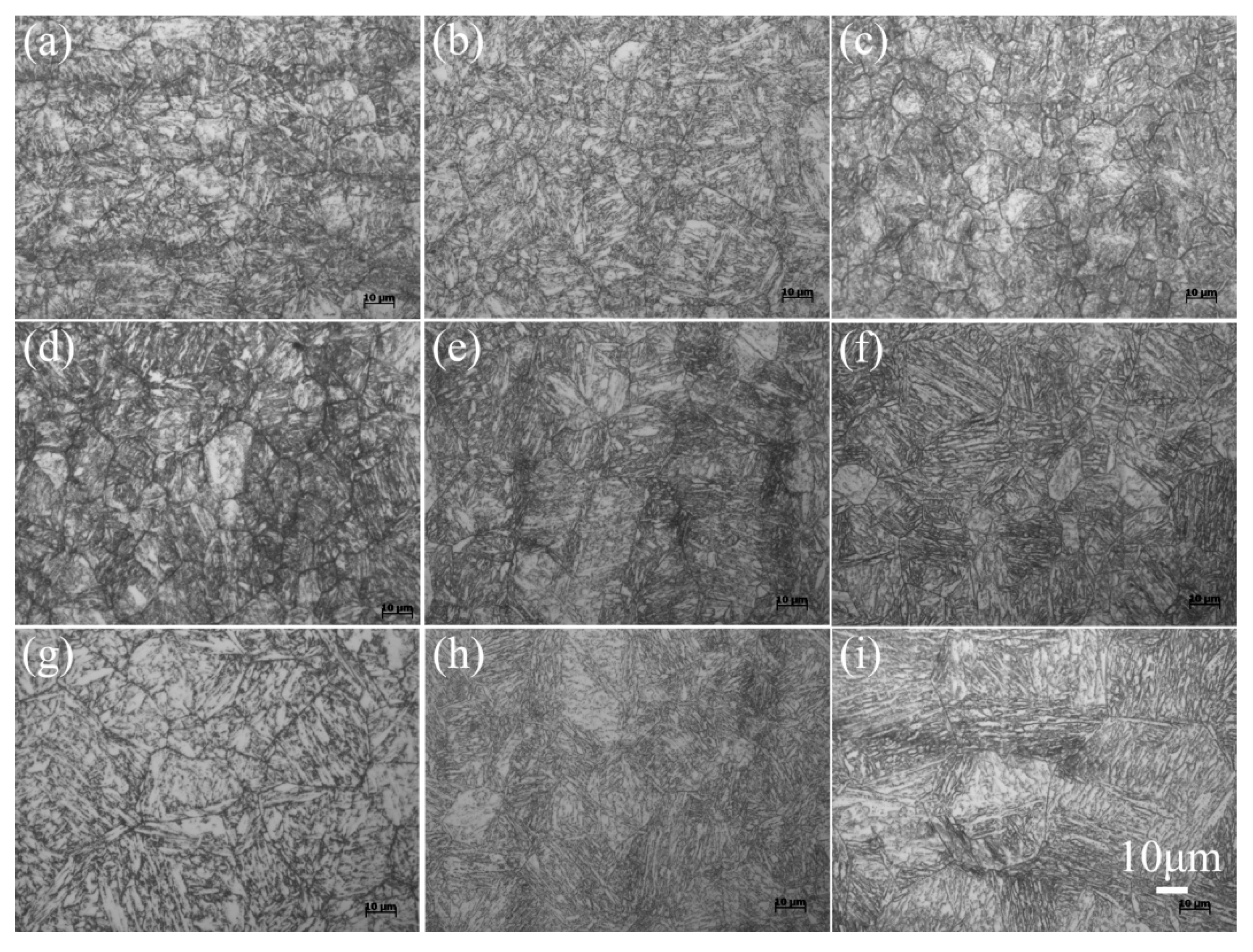
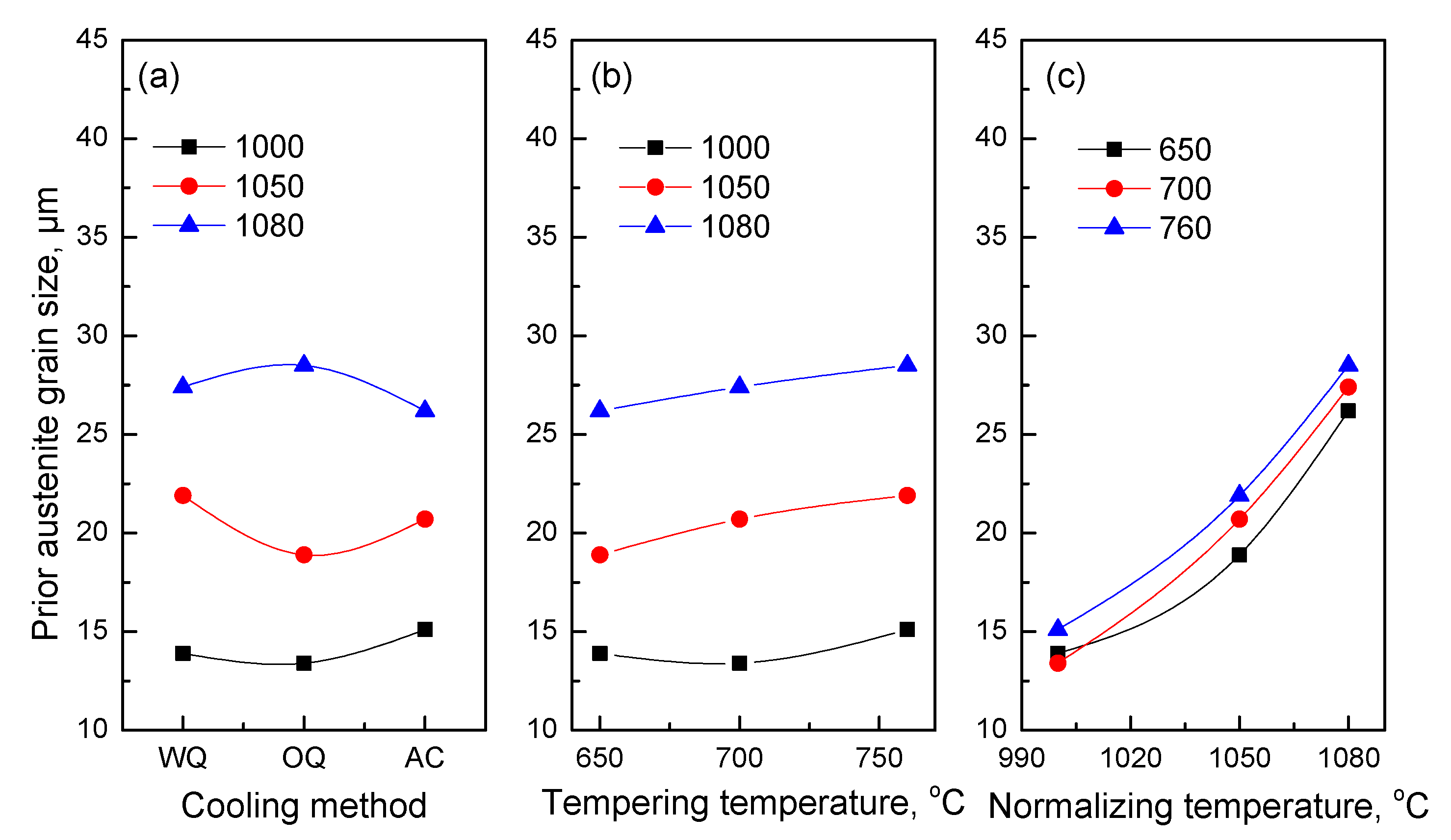
Figure 1 shows the microstructures of 15Cr12MoVWN steel under different heat treatment conditions. It is observed that 15Cr12MoVWN steel has a fully martensitic structure without formation of δ-ferrite. From Equation (1), Creq for 15Cr12MoVWN steel with the chemical composition in Table 1 is 6.48 wt.%, which is substantially lower than the critical content of 10.0 wt.% to eliminate the δ-ferrite formation. The variation in prior austenite grain (PAG) size with the heat treatment parameters is shown in Figure 2. The average grain size varies little with the different cooling methods and tempering temperatures. On the contrary, the PAG size changes obviously with different normalizing temperatures, especially for normalizing at 1080 °C. The higher the normalizing temperature, the greater the grain size. The normalizing temperature is therefore the most important factor affecting the PAG size among the influencing factors in the orthogonal design experiment.
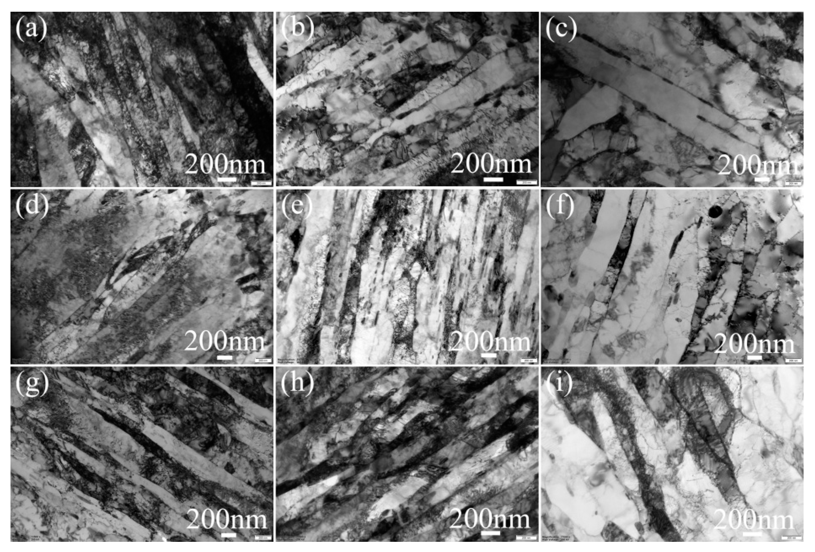
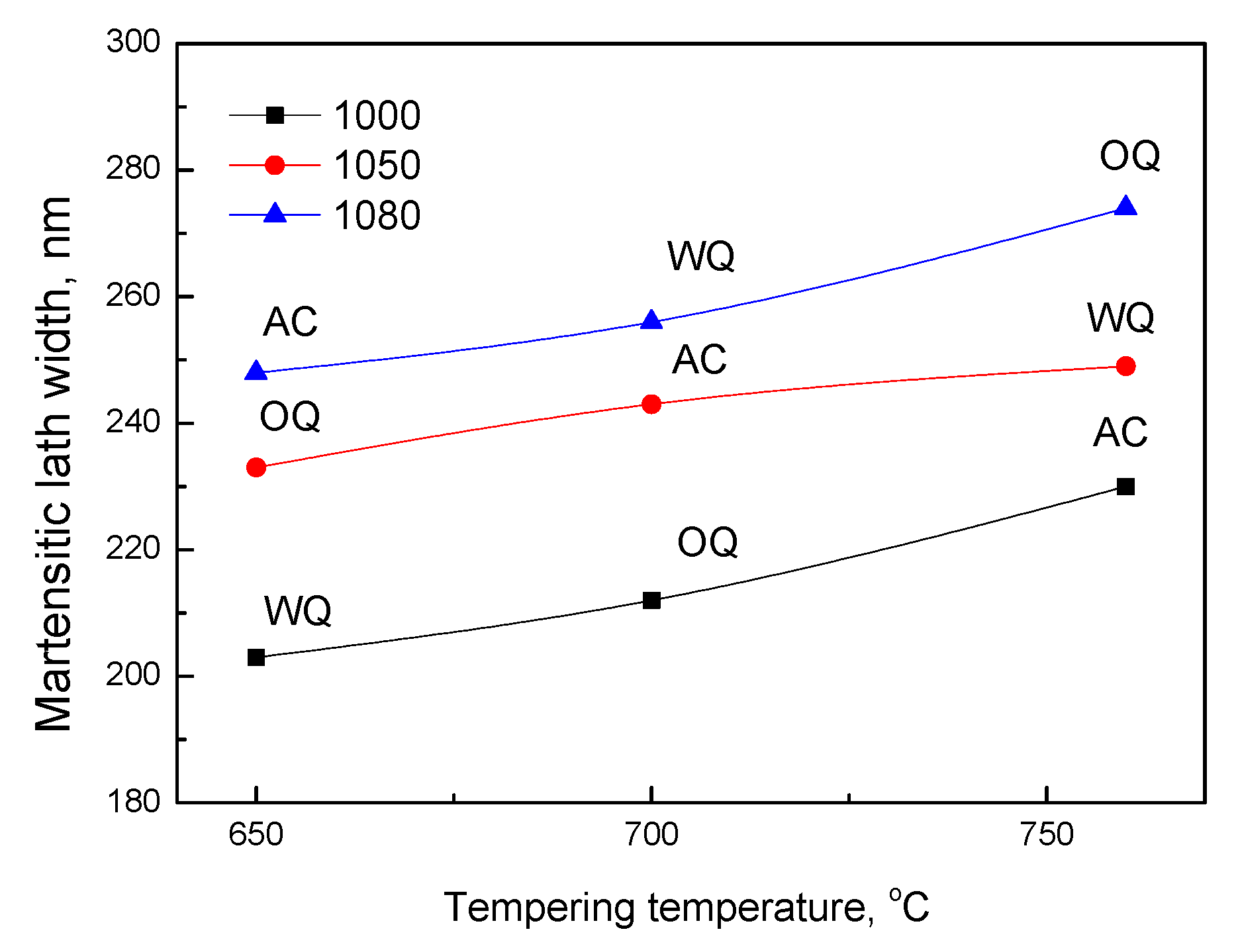
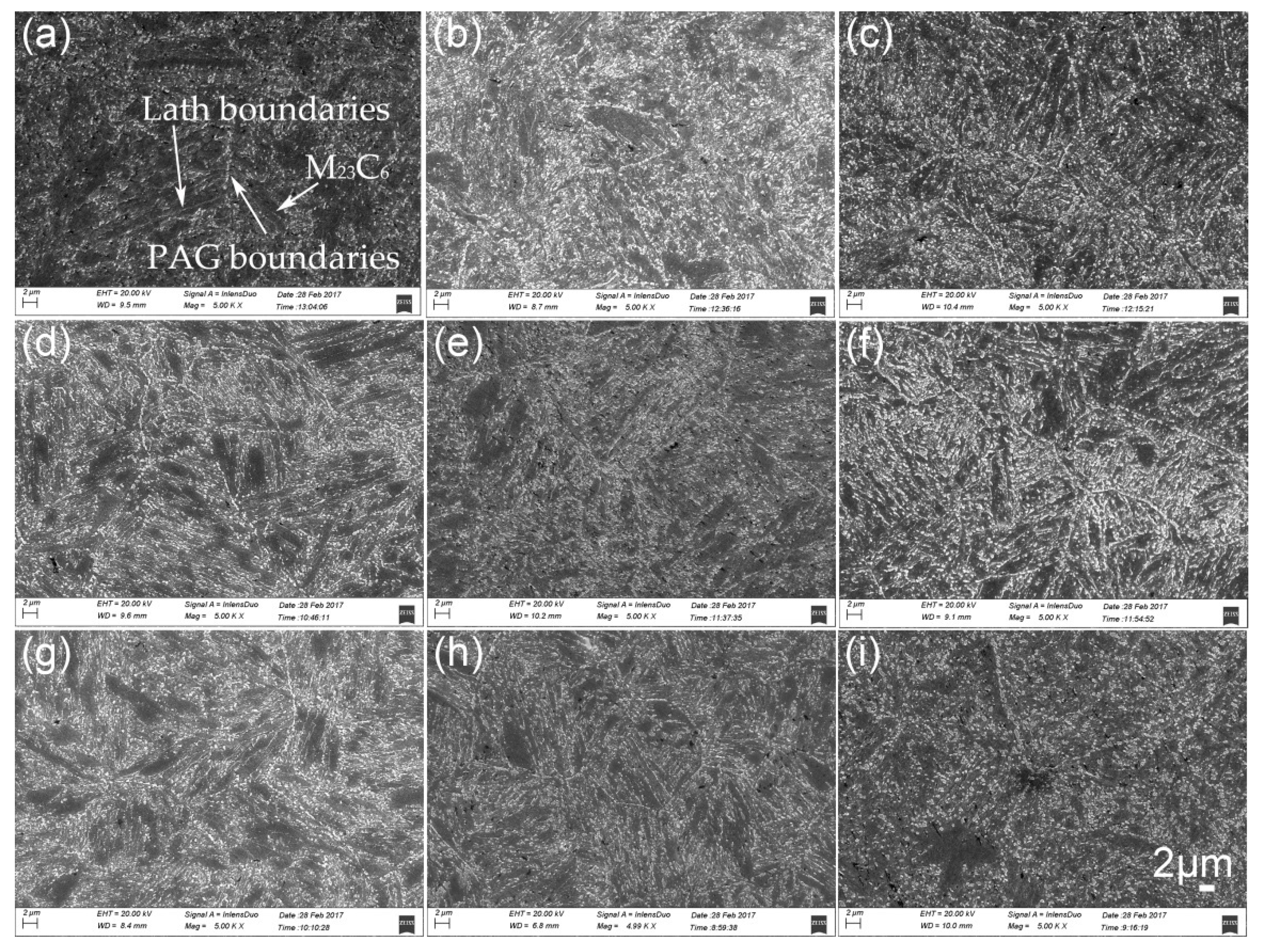
The morphology of the martensitic laths was analyzed by TEM and the results are shown in Figure 3. Fine martensitic laths dominated in the specimens tempered at 650 and 700 °C irrespective of the normalizing temperature and cooling method. When the tempering temperature increased to 760 °C, the dislocation recovery accelerated, and the dislocations in the martensitic lath passed through the precipitates by climbing or bypassing to form a dislocation wall, which promoted the formation of subgrains and accelerated the crushing of the lath. The width of martensitic lath was calculated and its relationship to the variation in heat treatment parameters is presented in Figure 4. From Figure 4, the increasing tendency of the martensitic lath width is low from 650 to 700 °C, but significant at 760 °C during tempering. The lath width increased with increasing grain size and normalizing temperature. It is also argued from Figure 4 that the tempering temperature was more effective in adjusting the lath width than the normalizing temperature. The present results of lath width variation in the 15Cr12MoVWN steel specimens are in good agreement with the literature [31].
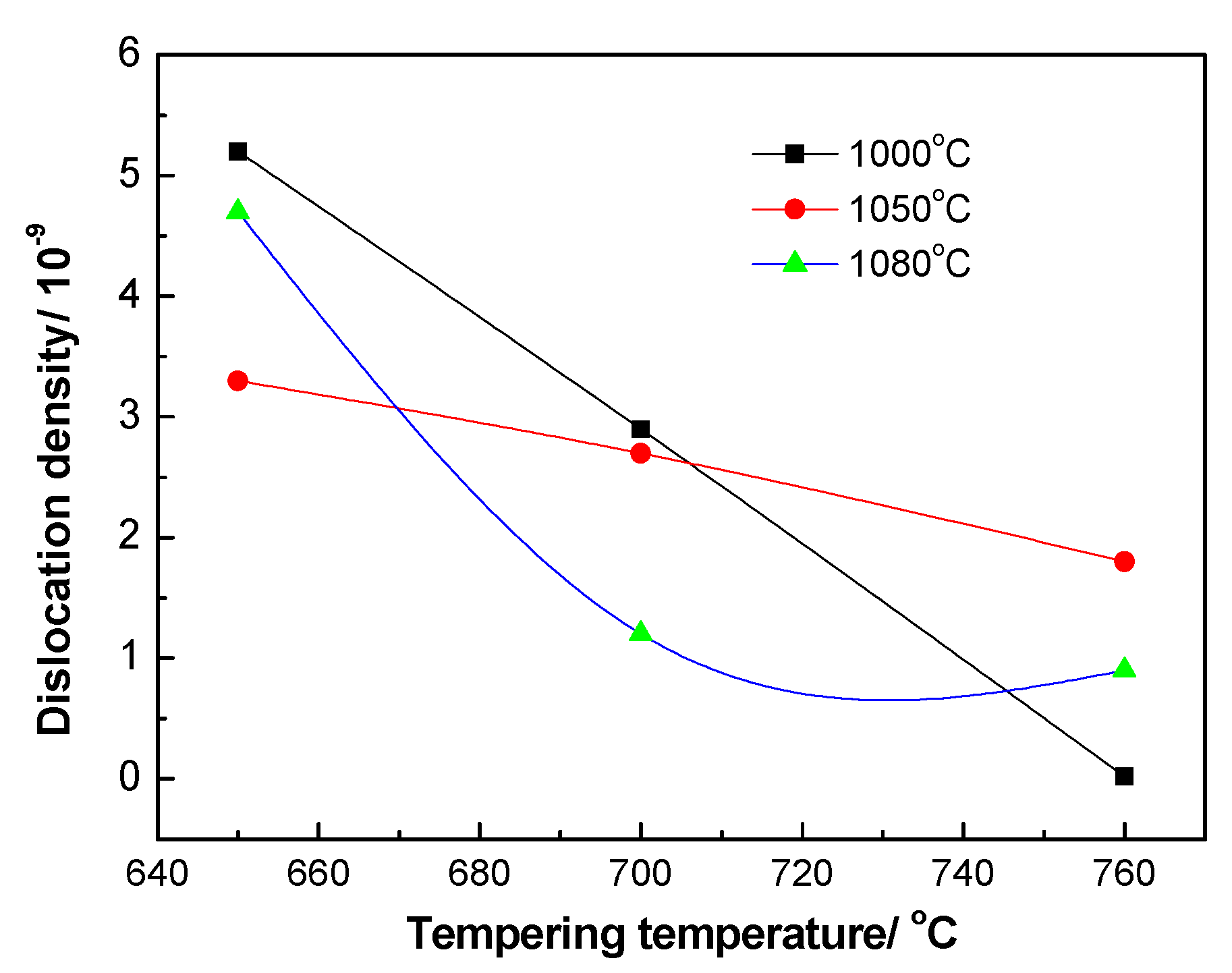
With the variation in lath width, dislocations diminish and the density decreases [32]. The dislocation density, , under different heat treatment conditions is characterized quantitatively based on the Williamson–Hall method [29,30] as shown in Equation (3) [33].
where, is the Burgers vector which has a value of 0.289 nm as reported in the literature [34]; and is the micro-strain, which refers to the irregular change in the crystal cell caused by micro-stress, and is calculated as the ratio of the diffraction peak broadening of the sample to the diffraction angle using the Jade software. The dislocation density under different heat treatment conditions was then calculated, and the results are shown in Figure 5. It is clear that the dislocation density decreased obviously with the increasing tempering temperature.
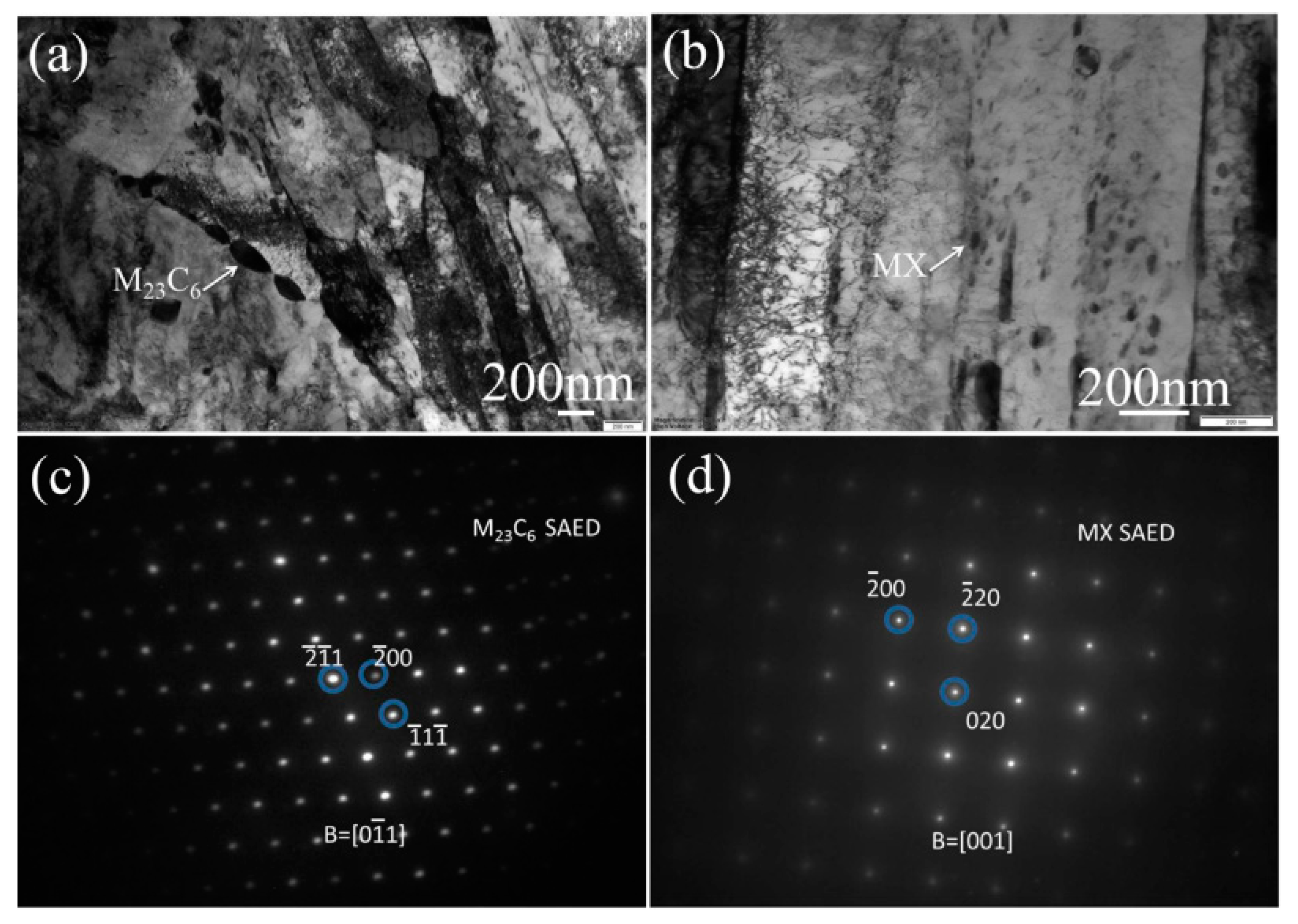
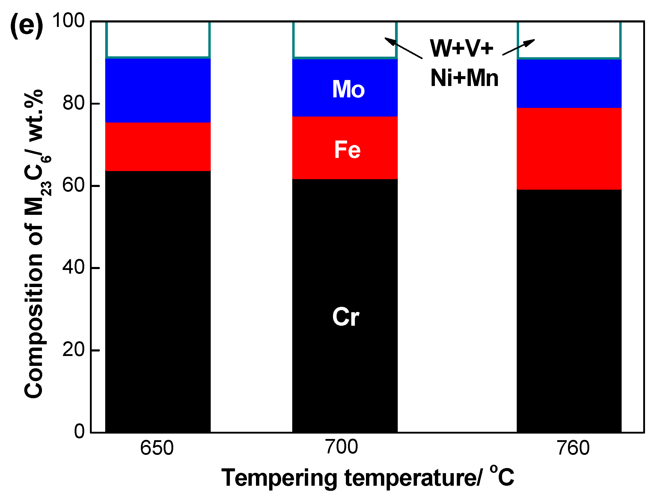
Two types of precipitates were observed in 15Cr12MoVWN steel. A representative morphology of the specimen normalized at 1000 °C, water quenched and tempered at 650 °C is shown in Figure 6. The elongated precipitates in Figure 6a distributed in the chain along the grain boundaries, whereas fine spheroid particles in Figure 6b distribute predominantly in the laths. Electron diffraction pattern analysis was used to identify the precipitates indicated by the arrows, and the selected area electron diffractions (SAEDs) are shown in Figure 6c,d. The precipitates in Figure 6a had an FCC structure, and the lattice constant, a, was 1.0809 nm, which is similar to that of Cr23C6 (a = 1.066 nm) reported in the literature [35]. The metal cluster, M, in M23C6 was mainly composed of Cr, Fe and Mo, as shown in Figure 6e. Fe, Mo and other elements were dissolved into Cr23C6 and replaced Cr to form a complex metal cluster which modified the lattice constant. From Figure 6d, the spheroid precipitates also had an FCC structure, and the lattice constant, a, was 0.4164 nm, which is between that of VC (a = 0.4165 nm) and VN (a = 0.41347 nm). The replacement of C by N and V by Cr modifies the lattice constant of VC. Therefore, the precipitate in Figure 6b was identified as (V,Cr), (C,N) or MX. The size of MX was below 50 nm, which is substantially smaller than that of M23C6.
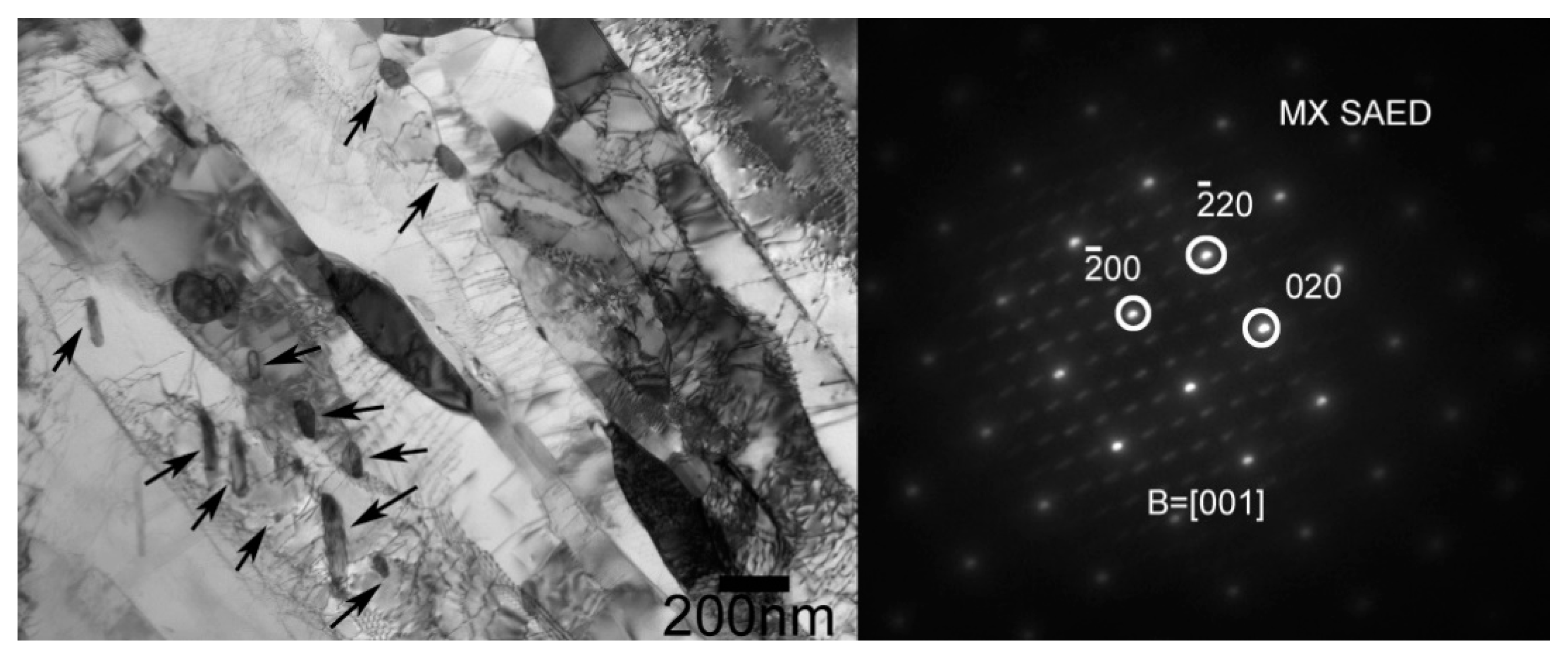
MX particles were also identified in the specimens normalized at 1080 °C and tempered at 760 °C. They were predominantly distributed at the martensitic lath boundaries and in the laths, as indicated by the arrows in Figure 7. It is clear that the particles pinned the dislocation, hindered the dislocation movement and hindered the lath mergence and growth when they were at the lath boundaries.
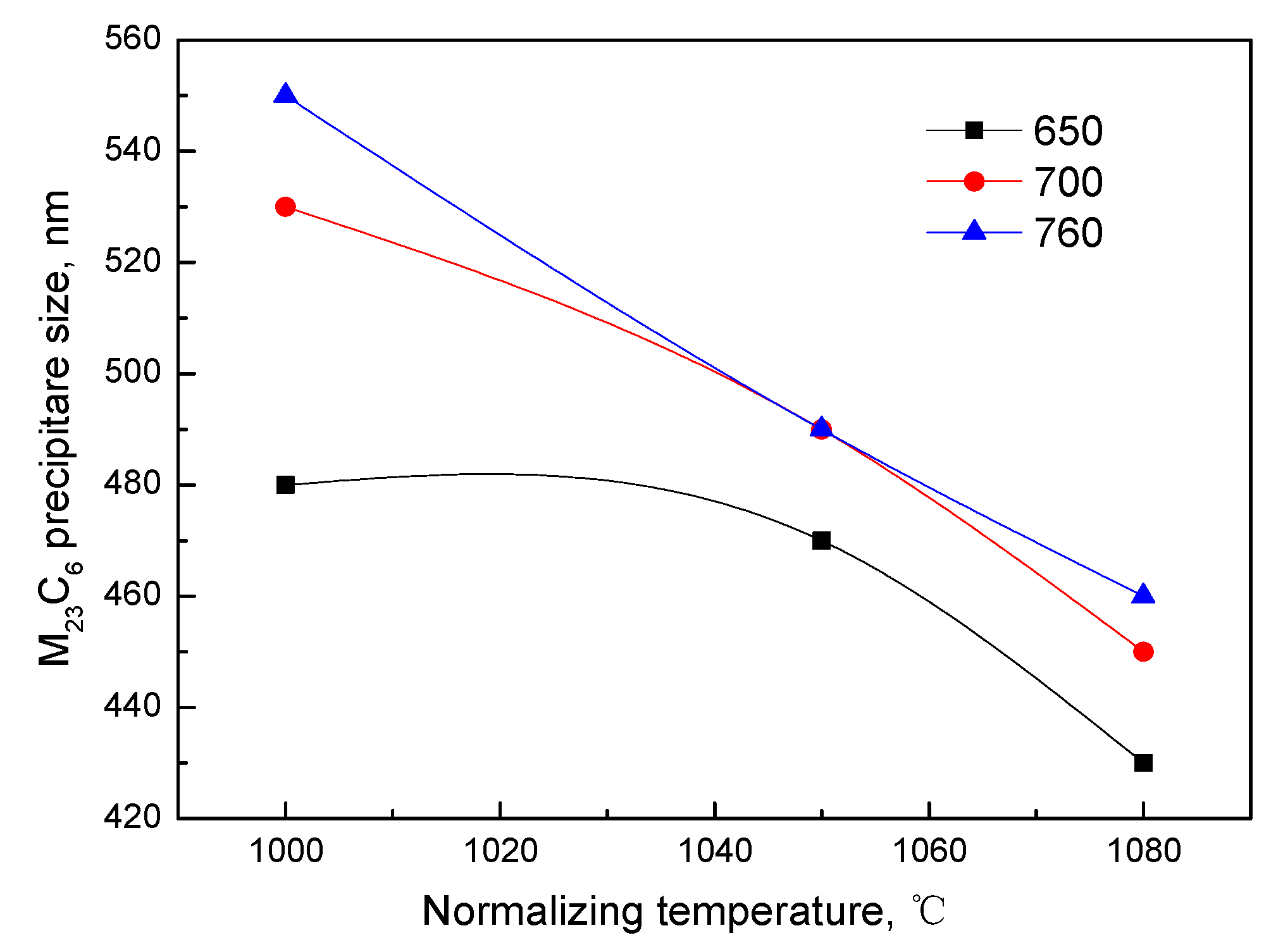
The distribution of M23C6 was also investigated using SEM, and the results are shown in Figure 8. The combination of high-temperature normalization followed by tempering at 650–760 °C (Figure 8d–h) or low temperature normalization followed by tempering at 700–760 °C (Figure 8b,c) is recommended because M23C6 particles were distributed homogeneously at the boundaries of PAG and laths. One hundred M23C6 particles at grain boundaries were calculated and the result of average particle size is shown in Figure 9. It is shown that the size of M23C6 decreased with increasing normalizing temperature, and with decreasing tempering temperature. The size of M23C6 varies little at the same normalizing temperature when the samples were tempered at 700 and 760 °C.
3.2. Tensile Properties
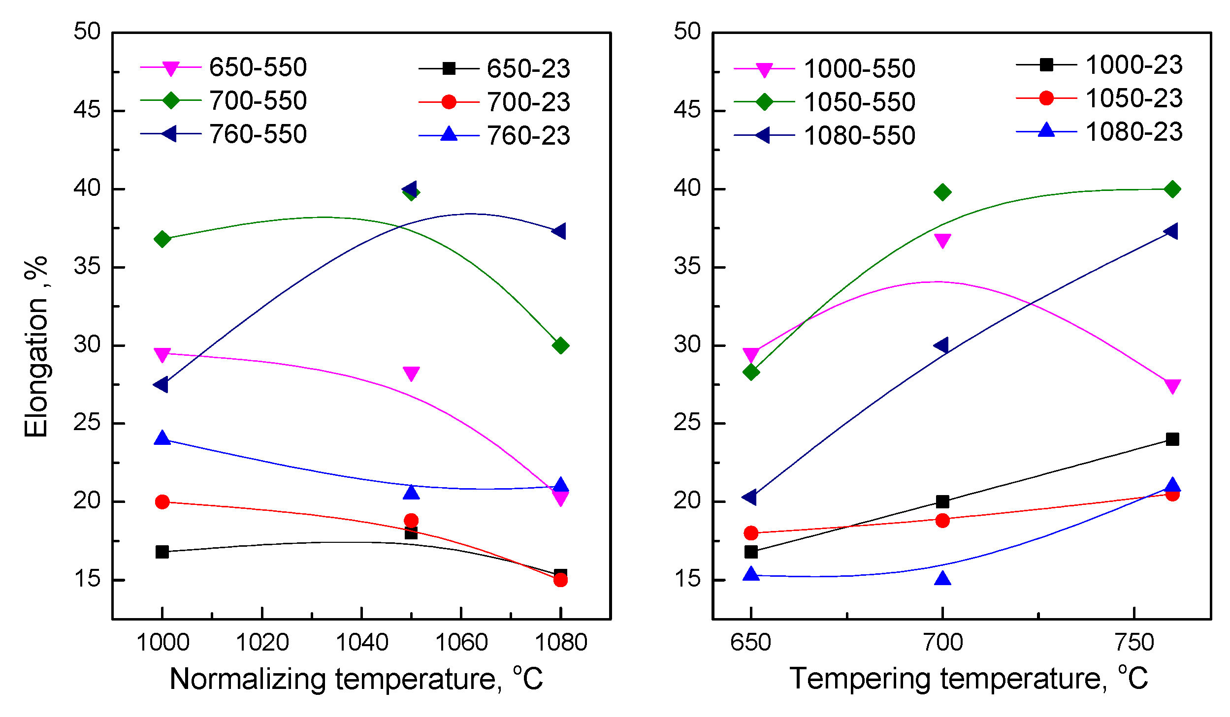
Tensile strengths of 15Cr12MoVWN steel at room temperature (23 °C) and 550 °C are shown in Figure 10. When tested at 23 °C, both the ultimate tensile strength (UTS) and yield strength (YS) were enhanced as the normalizing temperature increased from 1000 to 1050 °C, regardless of the tempering temperature. A further increase in the normalizing temperature up to 1080 °C had a detrimental effect on the UTS, with the exception of the specimen tempered at 700 °C, and normalizing at 1080 °C enhanced the YS with the exception of the specimen tempered at 650 °C. The UTS and YS decreased with increasing tempering temperature. For specimens tested at 550 °C, the UTS and YS increased with increasing normalizing temperature. Therefore, the higher normalizing temperature is recommended for 15Cr12MoVWN steel in the viewpoint of tensile strength.
The elongation of 15Cr12MoVWN steel tested at room temperature and 550 °C is shown in Figure 11. Specimens tempered at 760 °C had substantially higher elongation compared with those tempered 650 or 700 °C. The specimen normalized at 1000 °C had a higher elongation with an increase in tempered temperature than those at other normalizing temperature. It is argued that normalizing at high temperature was detrimental to elongation. For tensile specimens tested at 550 °C, those tempered at 650 °C at different normalizing temperatures had lower elongation. The elongation was lower for specimens tempered at 760 °C after normalizing at 1000 °C. It is concluded that the lower normalizing temperature and higher tempering temperature were recommend for the tensile ductility whether the specimens were tested at room temperature or 550 °C.
3.3. Fracture Morphology
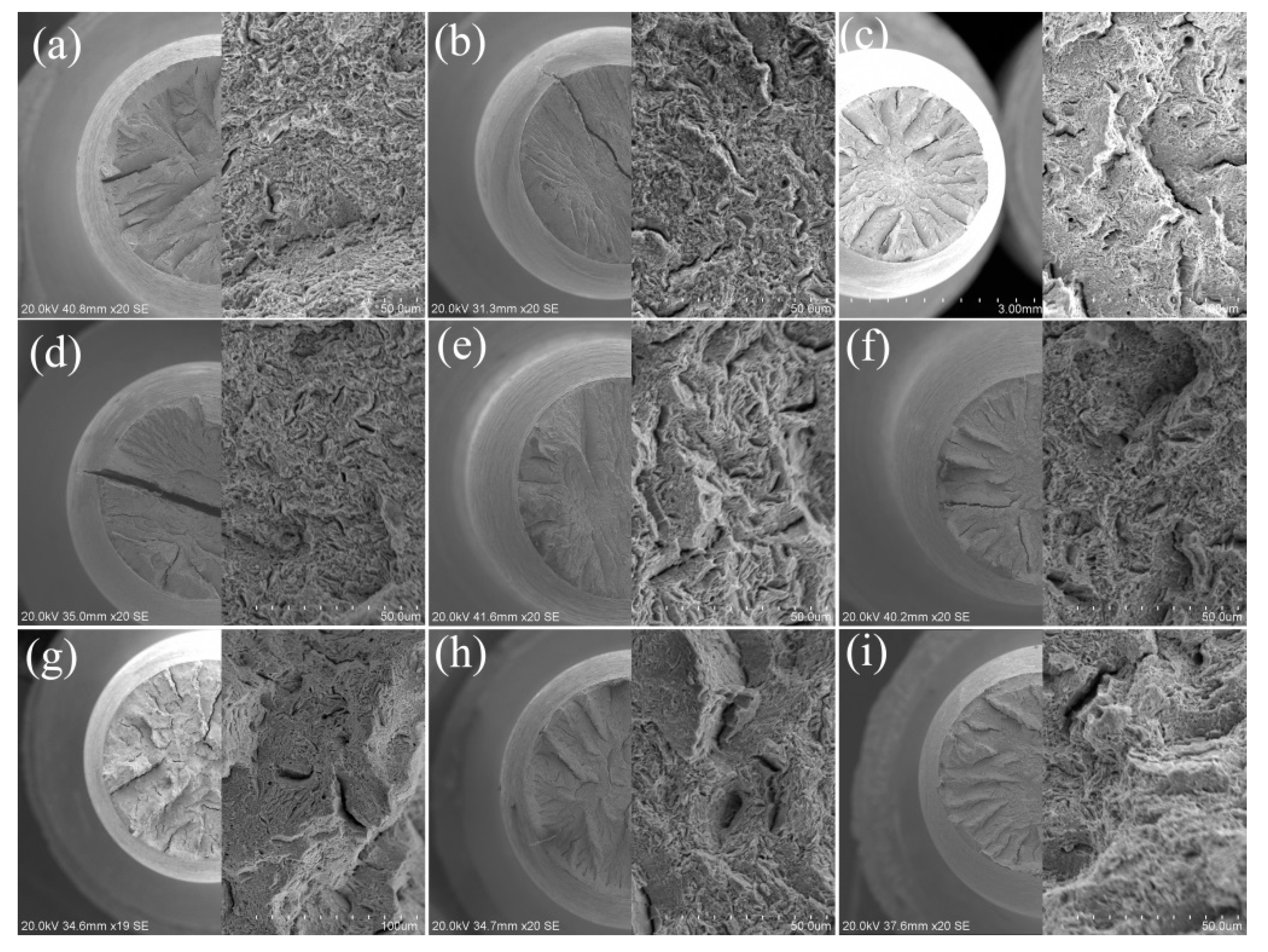
The fracture morphology of the ruptured tensile specimens was analyzed by SEM, and is shown in Figure 12. Radical cracks are shown in the morphology at different angular intervals, and the number of cracks and their depth increased with increasing tempering temperature especially at 700 °C as shown in Figure 12b,e,h. The fractographies with high resolution in each graph were taken from the center of the fractured specimens. The fibrous area in Figure 12c,f,i clearly indicates some secondary cracks in the fractographies as the tempering temperature increased while the normalizing temperature remained constant. These cracks are typically caused by second-phase particles or carbides. The homogeneous distribution of M23C6 in the specimens tempered at high temperature (Figure 8c,f) is favorable for uniform deformation during the tensile tests. On the contrary, the fractographies in Figure 12a,d show quasi-cleavage fracture with step and ligule patterns generated from the inhomogeneous M23C6 formation (Figure 8a,d). A large external force is required to break a material containing deep cracks, as shown in Figure 10. The dimples deepened with increasing tempering temperature, but the opposite trend occurred with increasing normalizing temperature.
4. Discussion
4.1. Relationship between Heat Treatment and Microstructure
Orthogonal design experiments were conducted to investigate the microstructural evolution in 15Cr12MoVWN steel, which is based on HT-9 steel and has a lower C content. The microstructure of 15Cr12MoVWN steel is composed of fully martensite as shown in Figure 1 and Figure 3. δ-ferrite was not detected under any of the heat treatment conditions. The main precipitates were identified as M23C6 and MX. As shown in the present research, the PAG size, the lath width, the density of dislocations and the distribution and particle size of M23C6 were affected by parameters of normalization and tempering.
The cooling method and tempering temperature had little influence on the PAG size. However, the normalizing temperature had the greatest influence on the PAG size, as shown in Figure 2. The grain size varied owing to the motivation of atoms. The increase in normalizing temperature accelerated the movement of atoms, and therefore promoted the migration of grain boundaries and the agglomeration of grains. In contrast, M23C6 carbides at the grain boundaries were dissolved into the matrix during normalization at high temperatures, and their effects on the pinning of grain boundaries was weakened, which promoted grain growth.
The cooling method and tempering temperature had a certain influence on the evolution of lath width. The variation of the width of laths with the changes of cooling methods was not monotonic as shown in Figure 4. As proposed from orthogonal analysis of HT-9 steel [36], cooling methods had less significant influence on the martensitic width compared with normalizing or tempering temperatures. A further study focused on the cooling methods on the microstructural evolution of 15Cr12MoVWN steel will be conceived in our following research on the condition of normalization at 1050 °C and tempering at 700 °C. As shown in Figure 4, the martensitic lath width increased slowly from 650 to 700 °C with an abrupt increase under the condition of tempering at 760 °C. Part of the martensitic lath boundary disappeared, and the neighboring laths combined during tempering, which resulted in the martensitic lath widening, and this tendency turned evidently with increasing tempering temperature.
The dislocation substructure was generated from the martensitic transformation during the cooling process following normalization. During tempering at 650–760 °C, the stored energies from the martensitic transformation were released, the dislocations moved constantly, and the dislocation density reduced. The higher the tempering temperature, the greater the dislocation movement and the lower the dislocation density. Therefore, the tempering temperature is an important factor in determining the dislocation density as shown in Figure 5. It also shows that normalizing temperature and cooling methods had monotonous influence on the variation of dislocation densities.
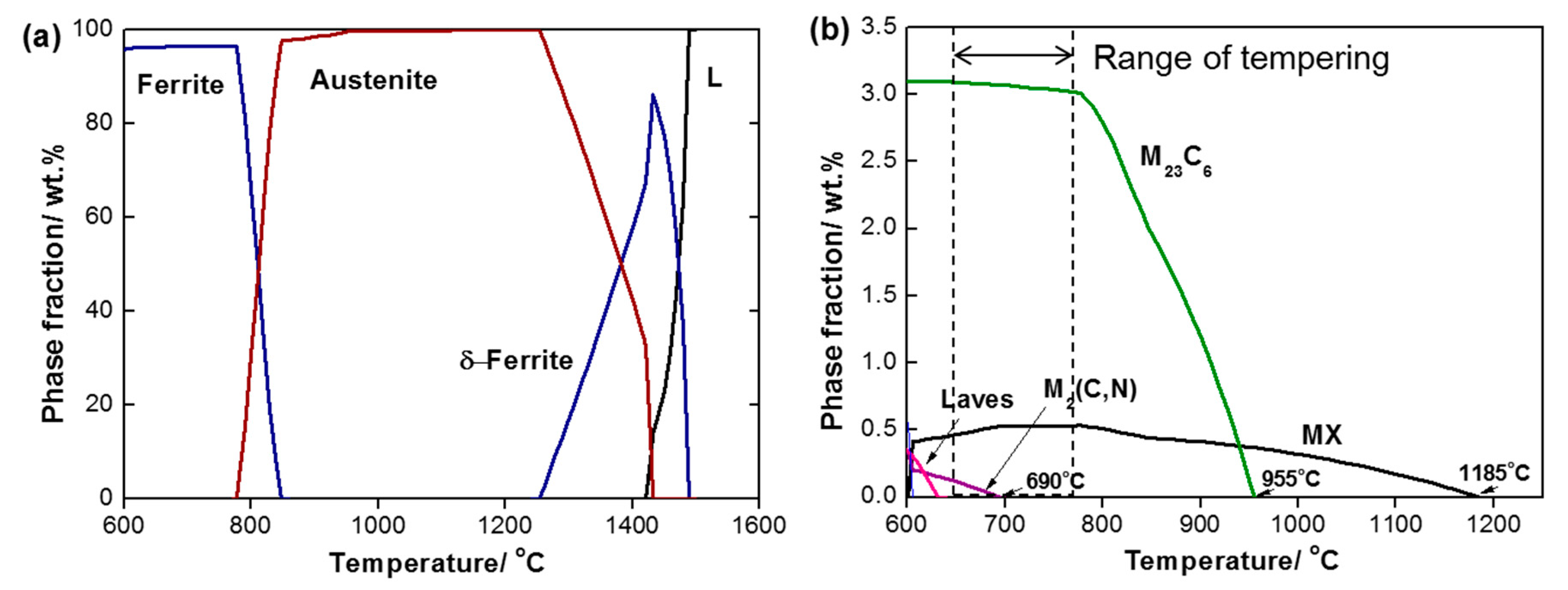
Figure 9 indicates that the normalizing temperature had a significant influence on the M23C6 evolution in 15Cr12MoVWN steel. The influence on M23C6 is attributed to the difference in carbide dissolution or the variation of PAG size. The equilibrium phases above 600 °C included δ-ferrite, M23C6, MX, M2(C, N) and Laves phase and their weight fractions at each temperature were given in Figure 13. M23C6 and MX were identified by experimental examinations. M2(C, N) and Laves phase were not observed from experimental examinations. No δ-ferrite was detected in specimens of 15Cr12MoVWN steel because of the careful control of hot processing and heat treatment parameters as shown in Section 3.1. From the thermodynamic calculation in Figure 13, the dissolved temperatures of M23C6 and MX were approximately 955 °C and 1185 °C, respectively. This means that M23C6 was completely dissolved at 1000–1080 °C in theory. As the normalizing temperature increased from 1000 to 1080 °C, the phase fraction of MX decreased from 0.3% to about 0.2%. The MX dissolution of 0.1% provided limited free C to influence the behavior of M23C6 during tempering. We consider the difference in Figure 9 to be attributed to the grain size. As shown in Figure 2c, the PAG size of the specimen normalized at 1080 °C and tempered at 760 °C was approximately 40 μm, which is more than twice that of the specimens normalized at 1000 °C or 1050 °C following the same tempering at 760 °C. For tempering at a certain temperature, the evolution of carbides was mainly determined by the diffusion of carbide-formers such as Cr, Fe and Mo. The distance of Cr, Mo from the matrix to the vicinity of grain boundaries was significantly affected by the grain size, according to Equation (4)
where is the diffusion time of the atoms, M, from the matrix to the grain boundaries; d the average PAG size; and are the concentrations of C, Cr, Fe or Mo in the matrix before tempering; is the concentration of Cr, Fe or Mo at the interface of the M23C6/matrix; and DM the diffusion coefficient for Cr, Fe or Mo. Equation (4) was rearranged as follows.
In the present study, , , and DM were treated to be equal because of the complete dissolution of M23C6 at 1000–1080 °C. Therefore, the concentration of Cr, Fe or Mo in front of the M23C6/matrix interface was reduced significantly by the increase in grain size, d. The increase in particle size was then attributed to Ostwald coarsening instead of the diffusion-controlled precipitation. The variation in M23C6 particle size with the tempering temperature was also inferred from the Equation (5) because of the increments in the diffusion coefficient DM.
Although predicted by thermodynamic calculations as shown in Figure 13b, Cr-rich M2(C, N) and Laves phases were not identified in the present study.
4.2. Relationship between Microstructure and Tensile Properties
Strengthening methods for ferritic/martensitic steels include fine-grain strengthening, solid solution strengthening, precipitate strengthening and dislocation strengthening. According to the fine-grain strengthening theory, the tensile strength decreased with increasing the PAGs as shown in Figure 2. However, the tensile strength increased with normalizing temperature, or strictly speaking, the increase of grain size from Figure 10. Therefore, the variation in grain size or normalizing temperature, therefore, should not be the main factor to influence the tensile properties of 15Cr12NiMoVWN steel. According to Fan et al. [37], the increased amount of the alloying elements caused an increase in strength of 1Cr12NiMo steel. From Figure 13, the amounts of M23C6 in specimens tempered at 650, 700 and 760 °C were 2.87%, 2.83% and 2.83%, respectively. The amount of MX varied little. It is speculated that solid solution strengthening generated from M23C6 and MX dissolution was also not the primary cause of the variation of tensile strength in Figure 10.
As shown in Figure 4, the lath width increased with increasing tempering temperature. The width increased slowly from 650 to 700 °C and abruptly at 760 °C. It is assumed that the martensitic lath fragmented gently at 650 or 700 °C, but fragmented completely and appears to be cellular substructure at 760 °C (Figure 3c,f,i). The larger the martensitic lath, the worse the plasticity and the lower the tensile strength of 15Cr12MoVWN steel as shown in Figure 10 and Figure 11. Therefore, the martensitic lath width is the main microstructural factor influencing the tensile properties of 15Cr12MoVWN steel.
The main precipitates in 15Cr12MoVWN steel identified as M23C6 and MX were effective in preventing grain growth and lath widening. These were manipulated to improve the tensile strength of ferritic/martensitic steels [38]. However, in the present study, there was a critical size of M23C6 particle that influenced the tensile strengths favorably. With increasing M23C6 size, the pinning function on the PAGs, lath boundaries and dislocations weakened, and the large grain size and wide martensitic laths also reduced the ductility of 15Cr12MoVWN steel. M23C6 size tempered at 650 °C in Figure 9 decreased between 1000 and 1050 °C, and the tensile strength (Figure 10) increased slowly. After normalization at 1080 °C followed by tempering, specimens, which contained M23C6 particles, exhibited a decreased tensile strength. It is assumed then that the critical M23C6 size was in the range of 470–490 nm for 15Cr12MoVWN steel. The MX (Figure 6b and Figure 7) in the laths, pinned the dislocations and prevented merging, thereby improving the tensile strength. The reduction in elongation with increasing normalizing temperature was attributed to the coarsening of the grains from Figure 11. The enhancement in elongation with increasing tempering temperature was attributed to the reduction in dislocation density from Figure 3 and Figure 5.
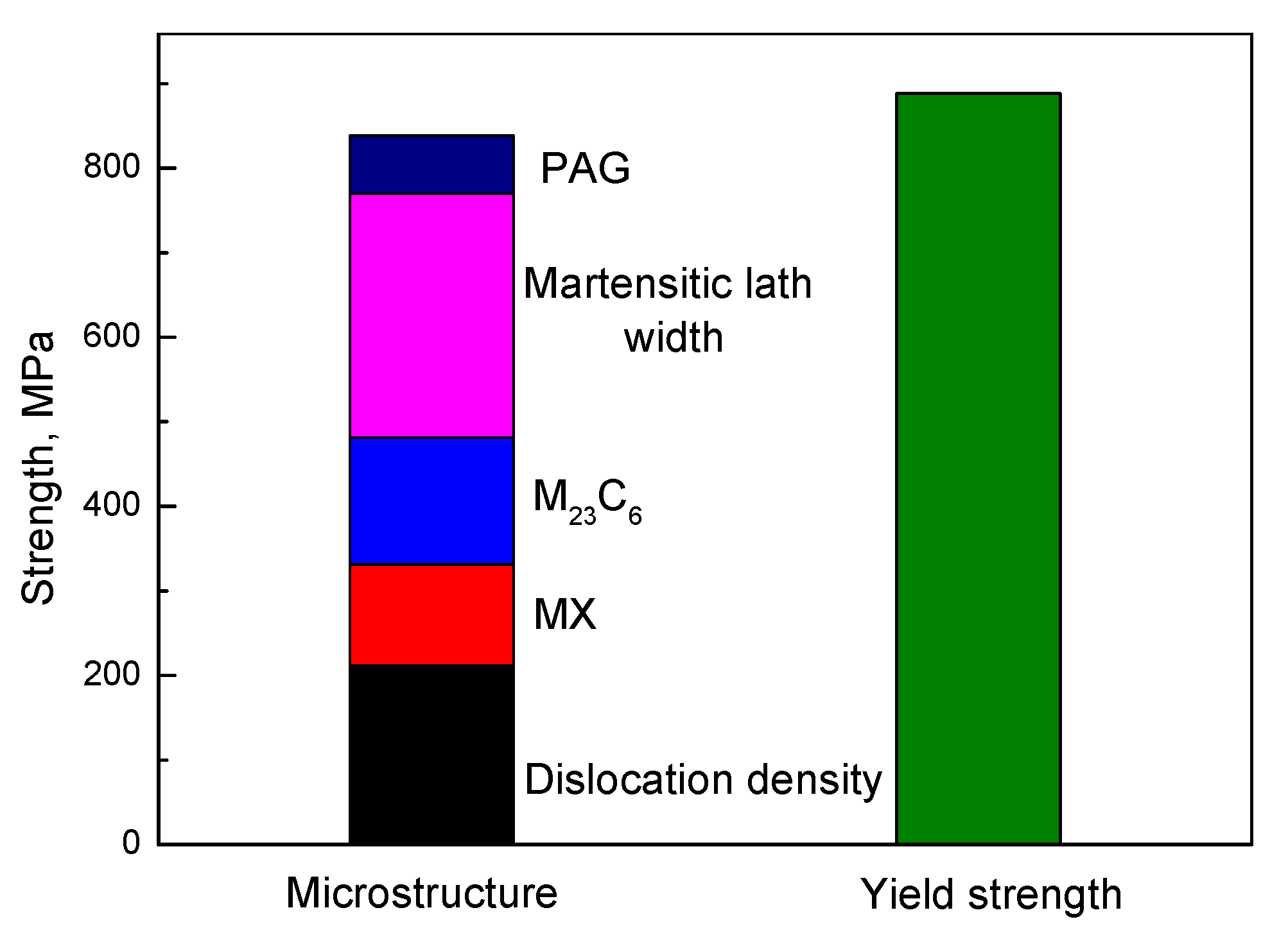
To estimate the strengthening contribution from dislocations, precipitates (MX and M23C6), laths and grain boundaries, the equations [39,40] Δσdis = 0.5 Mμbρ1/2 for dislocations, Δσp = Mαμb(Nd)1/2 for MX and M23C6, Δσl = Mμb/λ for martensitic laths and Δσg = 4380 Mμb/(m)1/2 for grain boundaries, respectively, where M is the Taylor factor and equal to 2.9 for ferritic heat resistant steels, μ is shear modulus and 80 GPa at 25 °C and 62 GPa at 550 °C for 15Cr12MoVWN steel, b is the magnitude of Burgers vector with a value of 0.25 nm, ρ is the dislocation density, α is a size-dependent strength factor with values from 0.1757ln(2.7013d) and the d is the size/diameter of precipitates, N is the number density of precipitates, λ is the lath width and m is the PAG size. We take the specimen in conditions of normalization at 1000 °C and tempering at 650 °C to illustrate the calculated strength increment for each microstructural feature and the results were plotted in Figure 14. It is clearly shown that the strengthening mechanism in 15Cr12MoVWN steel in a descending order was martensitic lath, dislocation, M23C6, MX and grain boundaries of PAG. The strengthening contribution from microstructural features in other heat treatment conditions showed the same trend as illustrated above.
4.3. Recommended Heat Treatment with Respect to Tensile Properties of 15Cr12MoVWN Steel
The tensile properties of 15Cr12MoVWN steel should satisfy the requirements of minimum YS, UTS and elongation at room temperature of 570 MPa, 665 MPa and 17%, respectively; and 340 MPa, 450 MPa and 20% at 550 °C, respectively. When the samples were tested at 550 °C, the results of YS and UTS are closer or higher than that tested at 250 °C with no radiation [17]. From Figure 10, normalization can be conducted at temperatures in the range of 1000–1080 °C followed by OQ or AC and tempering at temperatures in the range of 650–760 °C. However, normalizing at 1080 °C and tempering at 650 °C is not recommended from the viewpoint of tensile ductility. Therefore, the recommended heat treatment for 15Cr12MoVWN steel includes two steps composed of normalizing at 1050 °C followed by AC and tempering at 700 °C. In this condition, the tensile properties were 810 MPa (YS), 1014 MPa (UTS) and 18.8% (elongation) tested at room temperature, the values were 469 MPa (YS), 577 MPa (UTS) and 39.8% (elongation) for specimens tested at 550 °C.
5. Conclusions
In this study, we investigated the evolution of the microstructure of 15Cr12MoVWN steel by DSC and orthogonal design experimental method. The influence of heat treatment parameters on tensile properties was evaluated by tensile tests at 23 and 550 °C. The microstructure and strengthening mechanism of 15Cr12MoVWN steel were also discussed. The concluding remarks are:
- (1)
- The DSC results reveal that the phase transformation temperatures of 15Cr12MoVWN steel, Ac1, Ac3 and Tc were 802, 904 and 725 °C, respectively. These results provide the theoretical basis for the design of parameters of heat treatment process.
- (2)
- Based on the tensile strength and elongation at 23 and 550 °C, the optimized heat treatment parameter was determined: normalizing at 1050 °C, air cooling to room temperature and tempering at 700 °C. The tensile properties of specimens in optimized heat treatment condition were 1014 MPa (UTS), 810 MPa (YS) and 18.8% (elongation) tested at 23 °C, and the values were 577.5 MPa (UTS), 469 MPa (YS) and 39.8% (elongation) tested at 550 °C.
- (3)
- The martensitic lath width and dislocation were the main microstructural factors influencing the tensile strength of 15Cr12MoVWN steel. The strengthening contribution from M23C6 and MX was higher than that from grain boundaries of PAG and was the other important factor for strengthening. The average sizes of PAG and M23C6 particles were the main factors influencing the tensile ductility. Tempering temperature had the most significant influence on the evolution of precipitates and dislocation densities. Normalizing temperature had the most significant influence on the coarsening of PAG and M23C6. Cooling methods had less influence in both microstructure and tensile properties compared with the other two heat treatment parameters.
Author Contributions
T.M. and X.H. conceived and designed the study; X.H. helped to polish the English language for this work; P.W. helped to give suggestions and gave suggestions on the structures of this work. All authors have read and agreed to the published version of the manuscript.
Funding
This work was supported by the National Key Technology R&D Program, China (No. 149601A-A033) and Natural Science Foundation Guidance Plan of Liaoning Province (No. 2019-ZD-0362).
Conflicts of Interest
The authors declare no conflict of interest.
References
- Liu, J.; Liu, W.; Hao, Z.; Shi, T.; Kang, L.; Cui, Z.; Yun, D. Effects of Silicon content and tempering temperature on the microstructural evolution and mechanical properties of HT-9 steels. Materials 2020, 13, 972. [Google Scholar] [CrossRef] [Green Version]
- Su, Z.; Ye, C.; Yan, F. Sodium Cooled Fast Breeder Reactor; Atomic Energy Press: Beijing, China, 1991; p. 165. [Google Scholar]
- Tao, X.G.; Han, L.Z.; Gu, J.F. Effect of tempering on microstructure evolution and mechanical properties of X12CrMoWVNbN10–1–1 steel. Mater. Sci. Eng. A 2014, 618, 189–204. [Google Scholar] [CrossRef]
- Abe, F.; Noda, T.; Araki, H.; Okada, M. Development of Reduced-Activation Martensitic 9Cr Steels for Fusion Reactor. J. Nucl. Sci. Technol. 1994, 31, 279–292. [Google Scholar] [CrossRef]
- Klueh, R.L.; Harries, D.R. High-Chromium Ferritic and Martensitic Steels for Nuclear Applications; ASTM: West Conshohocken, PA, USA, 2001; pp. 68–69. [Google Scholar]
- Klueh, R.L.; Nelson, A.T. Ferritic/martensitic steels for next-generation reactors. J. Nucl. Mater. 2007, 371, 37–52. [Google Scholar] [CrossRef]
- Sample, T.; Fenici, P.; Kolbe, H. Liquid metal embrittlement susceptibility of welded MANET II (DIN 1.4914) in liquid Pb-17Li. J. Nucl. Mater. 1996, 233, 244–247. [Google Scholar] [CrossRef]
- Uehira, A.; Ukai, S.; Mizuno, T.; Asaga, T.; Yoshida, E. Tensile Properties of llCr-0.5Mo-2W, V, Nb Stainless Steel in LMFBR Environment. J. Nucl. Sci. Technol. 2000, 37, 780–786. [Google Scholar] [CrossRef]
- Dvoriashin, A.M.; Porollo, S.I.; Konobeev, Y.V.; Gainer, F.A. Influence of high dose neutron irradiation on microstructure of EP-450 ferritic–martensitic steel irradiated in three Russian fast reactors. J. Nucl. Mater. 2004, 329, 319–323. [Google Scholar] [CrossRef]
- Rosenwasser, S.N.; Miller, P.; Dalessandro, J.A.; Rawls, J.M.; Toffolo, W.E.; Chen, W. The application of martensitic stainless steels in long lifetime fusion first wall/blankets. J. Nucl. Mater. 1979, 85, 177–182. [Google Scholar] [CrossRef]
- Cheon, J.S.; Lee, C.B.; Lee, B.O.; Raison, J.P.; Mizuno, T.; Delage, F.; Carmack, J. Sodium fast reactor evaluation: Core materials. J. Nucl. Mater. 2009, 392, 324–330. [Google Scholar] [CrossRef]
- Hojna, A.; Gabriele, F.D.; Klecka, J.; Burda, J. Behaviour of the steel T91 under uniaxial and multiaxial slow loading in contace with liquid lead. J. Nucl. Mater. 2015, 466, 292–301. [Google Scholar] [CrossRef]
- Abe, F. Precipitate design for creep strengthening of 9% Cr tempered martensitic steel for ultra-supercritical power plants. Sci. Technol. Adv. Mater. 2008, 9, 013002. [Google Scholar] [PubMed]
- Serra, E.; Perujo, A. The surface rate constants of deuterium in the martensitic steel DIN 1.4914 (MANET). J. Nucl. Mater. 1995, 223, 157–162. [Google Scholar]
- Ennis, P.J.; Zielinska-Lipiec, A.; Wachter, O.; Czyrska-Filemonowicz, A. Microstructural stability and creep rupture strength of the martensitic steel P92 for advanced power plant. Acta Mater. 1997, 45, 4901–4907. [Google Scholar]
- Totemeier, T.C.; Simpson, J.A.; Tian, H. Effect of weld intercooling temperature on the structure and impact strength of ferritic–martensitic steels. Mater. Sci. Eng. A 2006, 426, 323–331. [Google Scholar]
- Rowcliffe, A.F.; Robertson, J.P.; Klueh, R.L.; Shiba, K.; Alexander, D.J.; Grossbeck, M.L.; Jitsukawa, S. Fracture toughness and tensile behavior of ferritic–martensitic steels irradiated at low temperatures. J. Nucl. Mater. 1998, 258, 1275–1279. [Google Scholar]
- Yano, A.; Tanno, T.; Sekio, Y.; Oka, H.; Ohtsuka, S.; Uwaba, T.; Kaito, T. Tensile properties and hardness of two types of 11Cr-ferritic/martensitic steel after aging up to 45,000 h. Nucl. Mater. Energy 2016, 9, 324–330. [Google Scholar]
- Zhang, H.; Long, B.; Dai, Y. Metallography studies and hardness measurements on ferritic/martensitic steels irradiated in STIP. J. Nucl. Mater. 2008, 377, 122–131. [Google Scholar]
- Shikakura, S.; Nomura, S.; Ukai, S.; Seshimo, I.; Kano, Y.; Kuwajima, Y.; Ito, T.; Tutaki, K.; Fujita, T. Development of high-strength ferritic/martensitic steel for FBR core materials. J. At. Energy Soc. Jpn. 1991, 33, 1157–1170. [Google Scholar]
- Yoshikawa, K.; Iseda, A.; Yano, M.; Masuyama, F.; Daikoku, T.; Haneda, H. Proceedings of the 1st International Conference on Improved Coal-Fired Power Plants; Electric Power Research Institute: Palo Alto, CA, USA, 1986; pp. 123–124. [Google Scholar]
- Klueh, R.L.; Cheng, E.T.; Grossbeck, M.L.; Bloom, E.E. Impurity effects on reduced-activation ferritic steels developed for fusion applications. J. Nucl. Mater. 2000, 280, 353–359. [Google Scholar]
- Hu, Z.F.; He, D.H.; Mo, F. Carbides evolution in 12Cr martensitic heat-resistant steel with life depletion for long-term service. J. Iron Steel Res. Int. 2015, 22, 250–255. [Google Scholar]
- Tavassoli, A.A. The influence of radiation on the properties of welds and joints. J. Nucl. Mater. 1988, 155, 105–112. [Google Scholar]
- Schirra, S.M.; Ehrich, K. Development of a high strength martensitic CrNiMoVNb steel with 10.5%Cr and 0.11%C. In Advanced Heat Resistant Steels for Power Generation; EPRI: TR-111571; Viswanathan, R., Nutting, J., Eds.; IOM Communications: London, UK, 1999; pp. 586–595. [Google Scholar]
- Kim, S.H.; Song, B.J.; Ryu, W.S.; Hong, J.H. Creep rupture properties of nitrogen added 10Cr ferritic/martensitic steels. J. Nucl. Mater. 2004, 329, 299–303. [Google Scholar]
- Nishiyama, Y.; Sawaragi, Y.; Otsuka, N.; Hirata, H.; Kihara, S.; Kajigaya, I. Development of a new heat resistant steels for high temperature components of power generation. In Advanced Heat Resistant Steels for Power Generation; EPRI: TR-111571; Viswanathan, R., Nutting, J., Eds.; IOM Communications: London, UK, 1999; pp. 482–493. [Google Scholar]
- Klueh, R.L.; Kai, J.J.; Alexander, D.J. Microstructure-mechanical properties correlation of irradiated conventional and reduced-activation martensitic steels. J. Nucl. Mater. 1995, 225, 175–186. [Google Scholar]
- Aufrecht, J.; Leineweber, A.; Foct, J.; Mittemeijer, E.J. The structure of nitrogen-supersaturated ferrite produced by ball milling. Philos. Mag. 2008, 88, 1835–1855. [Google Scholar]
- Takebayashi, S.; Kunieda, T.; Yoshinaga, N.; Ushioda, K.; Ogata, S. Comparison of the dislocation density in martensitic steels evaluated by some X-ray diffraction method. ISIJ Int. 2010, 50, 875–882. [Google Scholar]
- Barbadikar, D.R.; Deshmukh, G.S.; Maddi, L.; Laha, K.; Parameswaran, P.; Ballar, A.R.; Peshwe, D.R.; Paretkar, R.K.; Nandagopal, M.; Mathew, M.D. Effect of normalizing and tempering temperatures on microstructure and mechanical properties of P92 steel. Int. J. Pres. Ves. Pip. 2015, 132, 97–105. [Google Scholar]
- Li, S.; Eliniyaz, Z.; Sun, F.; Shen, Y.; Zhang, L.; Shan, A. Effect of thermo-mechanical treatment on microstructure and mechanical properties of P92 heat resistant steel. Mater. Sci. Eng. A 2013, 559, 882–888. [Google Scholar]
- Williamson, G.K.; Smallman, R.E. Dislocation densities in some annealed and cold-worked metals from measurements on the X-ray debye-scherrer spectrum. Philos. Mag. 1956, 1, 34–36. [Google Scholar]
- Zlateva, G.; Martinova, Z. Microstructure of Metals and Alloys: An Atlas of Transmission Election Microscopy Images, 2nd ed.; CRC Press: New York, NY, USA, 2008; p. 36. [Google Scholar]
- Wang, W.; Liu, S.; Xu, G.; Zhang, B.; Huang, Q. Effect of thermal aging on microstructure and mechanical properties of China low-activation martensitic steel at 550 °C. Nucl. Eng. Technol. 2016, 48, 518–524. [Google Scholar]
- Ma, T.; Hao, X.; Liang, T.; Chen, B.; Wang, P.; Ma, Y.; Liu, K. Influence of orthogonal heat treatment on mechanical properties of HT-9 ferritic/martensitic steel. In Advances in Energy and Environmental Materials, Proceedings of the Chinese Materials Conference, Yinchuan City, China, 6–12 July 2018; A-03; Han, Y., Ed.; Springer Nature Singapore Private Limited: Singapore, 2018; pp. 85–94. [Google Scholar]
- Fan, R.; Gao, M.; Ma, Y.; Zha, X.; Hao, X.; Liu, K. Effects of heat treatment and Nitrogen on microstructure and mechanical properties of 1Cr12NiMo martensitic stainless steel. J. Mater. Sci. Technol. 2012, 28, 1059–1066. [Google Scholar]
- Peng, B.; Zhang, H.; Hong, J.; Gao, J.; Zhang, H.; Wang, Q.; Li, J. The effect of M23C6 on the high-temperature tensile strength of two austenitic heat-resistant steels: 22Cr-25Ni-Mo-Nb-N and 25Cr-20Ni-Nb-N. Mater. Sci. Eng. A 2011, 528, 3625–3629. [Google Scholar]
- Tan, L.; Graening, T.; Hu, X.; Zhong, W.; Yang, Y.; Zinkle, S.J.; Katoh, Y. Effects of carbonitrides and carbides on microstructure and properties of castable nanostructured alloys. J. Nucl. Mater. 2020, 540, 152376. [Google Scholar]
- Maruyama, K.C.; Sawada, K.; Koike, J.I. Strengthening mechanisms of creep resistant tempered martensitic steel. ISIJ Int. 2001, 41, 641–653. [Google Scholar]
Figure 1.
Optical micrographs of 15Cr12MoVWN steel under different heat treatment conditions. (a) 0W, (b) 0O, (c) 0A, (d) 5O, (e) 5A, (f) 5W, (g) 8A, (h) 8W, (i) 8O.
Figure 1.
Optical micrographs of 15Cr12MoVWN steel under different heat treatment conditions. (a) 0W, (b) 0O, (c) 0A, (d) 5O, (e) 5A, (f) 5W, (g) 8A, (h) 8W, (i) 8O.

Figure 2.
Average prior austenite grain (PAG) size of 15Cr12MoVWN steel with heat treatment parameters. (a): Cooling method; (b): Tempering temperature; (c): Normalizing temperature.
Figure 2.
Average prior austenite grain (PAG) size of 15Cr12MoVWN steel with heat treatment parameters. (a): Cooling method; (b): Tempering temperature; (c): Normalizing temperature.

Figure 3.
TEM micrographs of 15Cr12MoVWN steel under conditions of (a) 0W. (b) 0O. (c) 0A. (d) 5O. (e) 5A. (f) 5W. (g) 8A. (h) 8W. (i) 8O.
Figure 3.
TEM micrographs of 15Cr12MoVWN steel under conditions of (a) 0W. (b) 0O. (c) 0A. (d) 5O. (e) 5A. (f) 5W. (g) 8A. (h) 8W. (i) 8O.

Figure 4.
Average martensitic lath width of 15Cr12MoVWN steel according to heat treatment parameters.
Figure 4.
Average martensitic lath width of 15Cr12MoVWN steel according to heat treatment parameters.

Figure 5.
Variation in dislocation density with heat treatment temperature of 15Cr12MoVWN steel.

Figure 6.
TEM micrographs of 15Cr12MoVWN steel normalized at 1000 °C and tempered at 650 °C. (a) M23C6 at grain boundary, (b) MX in lath, (c) selected area electron diffraction (SAED) of M23C6 in (a), (d) SAED of MX in (b), (e) composition of metal cluster, M, in M23C6.
Figure 6.
TEM micrographs of 15Cr12MoVWN steel normalized at 1000 °C and tempered at 650 °C. (a) M23C6 at grain boundary, (b) MX in lath, (c) selected area electron diffraction (SAED) of M23C6 in (a), (d) SAED of MX in (b), (e) composition of metal cluster, M, in M23C6.


Figure 7.
TEM micrographs and the related SAED of MX in 15Cr12MoVWN specimen normalized at 1080 °C and tempered at 760 °C.
Figure 7.
TEM micrographs and the related SAED of MX in 15Cr12MoVWN specimen normalized at 1080 °C and tempered at 760 °C.

Figure 8.
SEM micrographs of M23C6 in 15Cr12MoVWN steel specimens under conditions of (a) 0W, (b) 0O, (c) 0A, (d) 5O, (e) 5A, (f) 5W, (g) 8A, (h) 8W, (i) 8O.
Figure 8.
SEM micrographs of M23C6 in 15Cr12MoVWN steel specimens under conditions of (a) 0W, (b) 0O, (c) 0A, (d) 5O, (e) 5A, (f) 5W, (g) 8A, (h) 8W, (i) 8O.

Figure 9.
Average M23C6 particle size at grain boundaries with variation in normalizing temperature.
Figure 9.
Average M23C6 particle size at grain boundaries with variation in normalizing temperature.

Figure 10.
Tensile strength of 15Cr12MoVWN steel under different heat treatment conditions.

Figure 11.
Elongation of 15Cr12MoVWN steel specimens under different heat treatment conditions.

Figure 12.
Tensile fractographies of 15Cr12MoVWN steel at room temperature under conditions of (a) 0W, (b) 0O, (c) 0A, (d) 5O, (e) 5A, (f) 5W, (g) 8A, (h) 8W, (i) 8O.
Figure 12.
Tensile fractographies of 15Cr12MoVWN steel at room temperature under conditions of (a) 0W, (b) 0O, (c) 0A, (d) 5O, (e) 5A, (f) 5W, (g) 8A, (h) 8W, (i) 8O.

Figure 13.
Relationship between phase fraction and temperature of 15Cr12MoVWN steel calculated by Thermo-Calc software based on the chemical composition in Table 1. (a): overall diagram; (b): partial diagram.
Figure 13.
Relationship between phase fraction and temperature of 15Cr12MoVWN steel calculated by Thermo-Calc software based on the chemical composition in Table 1. (a): overall diagram; (b): partial diagram.

Figure 14.
Microstructure contribution strength and yield strength of 15Cr12MoVWN steel.


Table 1.
Chemical composition of 15Cr12MoVWN steel (wt.%).
| C | Si | Mn | Cr | Mo | W | V | Ni | S | P | N | Fe |
|---|---|---|---|---|---|---|---|---|---|---|---|
| 0.15 | 0.04 | 0.58 | 12.20 | 0.90 | 0.50 | 0.29 | 0.69 | 0.002 | 0.003 | 0.106 | Bal. |
Table 2.
Influence factors and parameters for the orthogonal design experiment.
| No. | Austenitizing/°C | Tempering/°C | Cooling Method |
|---|---|---|---|
| 0W | 1000 | 650 | WQ a |
| 0O | 1000 | 700 | OQ b |
| 0A | 1000 | 760 | AC c |
| 5O | 1050 | 650 | OQ |
| 5A | 1050 | 700 | AC |
| 5W | 1050 | 760 | WQ |
| 8A | 1080 | 650 | AC |
| 8W | 1080 | 700 | WQ |
| 8O | 1080 | 760 | OQ |
Note: a water quenching; b oil quenching; c air cooling.
© 2020 by the authors. Licensee MDPI, Basel, Switzerland. This article is an open access article distributed under the terms and conditions of the Creative Commons Attribution (CC BY) license (http://creativecommons.org/licenses/by/4.0/).
Share and Cite
MDPI and ACS Style
Ma, T.; Hao, X.; Wang, P. Effect of Heat Treatments on Microstructural Evolution and Tensile Properties of 15Cr12MoVWN Ferritic/Martensitic Steel. Metals 2020, 10, 1271. https://0-doi-org.brum.beds.ac.uk/10.3390/met10091271
AMA Style
Ma T, Hao X, Wang P. Effect of Heat Treatments on Microstructural Evolution and Tensile Properties of 15Cr12MoVWN Ferritic/Martensitic Steel. Metals. 2020; 10(9):1271. https://0-doi-org.brum.beds.ac.uk/10.3390/met10091271
Chicago/Turabian StyleMa, Tingwei, Xianchao Hao, and Ping Wang. 2020. "Effect of Heat Treatments on Microstructural Evolution and Tensile Properties of 15Cr12MoVWN Ferritic/Martensitic Steel" Metals 10, no. 9: 1271. https://0-doi-org.brum.beds.ac.uk/10.3390/met10091271
Note that from the first issue of 2016, this journal uses article numbers instead of page numbers. See further details here.