Strength Calculation and Equal Load-Carrying-Capacity Design of an Undermatched HSLA Lap Joint under Out-of-Plane Bending


1
State Key Laboratory of Advanced Welding and Joining, Harbin Institute of Technology, Harbin 150001, China
2
Materials School, Heilongjiang Institute of Technology, Harbin 150050, China
*
Author to whom correspondence should be addressed.
Metals 2021, 11(1), 161; https://0-doi-org.brum.beds.ac.uk/10.3390/met11010161
Submission received: 1 December 2020
/
Revised: 4 January 2021
/
Accepted: 13 January 2021
/
Published: 16 January 2021
(This article belongs to the Special Issue Welding of Advanced High Strength Steel (AHSS))
Abstract
:This work aimed to design an undermatched lap joint that has an equal load-carrying capacity (ELCC) with a traditional equalmatched joint under out-of-plane bending. A weld strength calculation method was proposed based on the similarity of a lap joint and a T joint, as shown using linear elastic finite element (FE) analysis, and then applied in the analysis of a lap joint and the design of an ELCC lap joint. A single lap joint of HQ785 steel was chosen for experimental verification. The bending force limit of the ELCC joint was 93.35% of the theoretical prediction and 96.90% of the traditional equalmatched joint. The results show that the weld strength calculation method and the ELCC design method are reasonable and feasible.
1. Introduction
High-strength low-alloy steels (HSLA) are widely used to reduce the weight of welded structures while maintaining or enhancing security [1,2,3,4]. However, the effectiveness of HSLA for welding structures is severely limited by welding defects, especially cold cracking (hydrogen-induced cracking), which is one of the main causes of early failure [5,6,7]. Diffusible hydrogen, which is introduced by the storage conditions [8], the welding environment [9], or directly by the raw materials, is a necessary condition for hydrogen-induced cracking.
Preheating before welding and dehydrogenation [10] after welding can eliminate cold cracking, while increasing the energy consumption and deteriorating the working environment; furthermore, improper preheating will intensify the softening and embrittlement of the heat-affected zone [11,12]. Another strategy to prevent cold cracking is to develop special filler materials, such as low hydrogen filler materials, low carbon martensite, and austenitic-martensite dual phase filler materials [13]. Besides the long development cycle and high cost, this strategy is not practical for ultra-HSLA because the microstructure that is designed based on some strengthening mechanism is difficult to form or maintain under welding conditions.
Filler materials with lower strength and higher plasticity and toughness are used to get a high-quality joint with a lower preheating temperature or without preheating operations [14,15,16,17]. The strength of such an undermatched joint is between those of the filler materials and the base metal because the weld is strengthened metallurgically and is protected from deformation by the surrounding base metal [15,18]. As the weld thickness decreases, the strength increases but the plasticity decreases significantly. The fracture mode of the joint is a brittle fracture without obvious plastic deformation. Most undermatched joints are still the weakest position in a welding structure because of their insufficiency in load carrying capacity (LCC).
Note that the LCC is a different concept from strength: strength is a material parameter with the units of megapascals (MPa); LCC is the maximum load that the section of the joint can bear, with the units of megapascal meters squared (MPa∙m2), for example. The security of a welding structure requires that the LCC of the joint is equal to that of the base metal; this is a matter that concerns both the material performance and geometrical dimensions. Appropriately increasing the weld size of an undermatched joint can make the LCC of the weld equal to that of the base metal and improve the structural reliability. The shape optimization of the weld toe is imperative to eliminate the stress concentration caused by the increased weld size (weld reinforcement for a butt joint). A Baud streamline [19], a Neuber catenary curve [20], a Schnack transition curve [21], C. Mattheck stretch triangle [22], an elliptic, and a parabola are possible optimal shapes, which can be obtained by grinding [23] or tungsten argon arc welding (TIG) dressing [24,25]. In this way, the failure mode of an undermatched joint turns to ductile fracture, where the joint is no longer the weakness of welded structure; thus, the effectiveness of the base metal HSLA is fully demonstrated.
The main problem of the equal LCC (ELCC) design method mentioned above is its difference from the existing codes, especially when dealing with the reinforcement of a butt joint. However, increasing the area of the weld section is allowed for a lap joint, which is widely used in engineering because of its simplicity in pre-welding preparation and assembly. For a side fillet weld, both the throat depth and the length can be increased and the section area of the weld can be greatly increased, and thus, an extremely low matching ratio can be adopted. For a front fillet weld, only the throat depth can be increased to the thickness of the base metal and the minimum of matching ratio is limited; however, a relatively low matching ratio can still be adopted because the thickness of the joint is twice that of the base metal.
The strength calculation methods for a lap joint fillet weld that ELCC joints designs are based upon have been prescribed under most types of loads, except for out-of-plane bending [26].
In order to improve the out-of-plane bending LCC of an undermatched lap joint, this work established a strength calculation method for a lap joint based on the similarity of a lap joint and a T joint, as shown using linear elastic finite element (FE) analysis. Then the failure and LCC of a lap joint was predicted and an undermatched lap joint that has an ELCC with a traditional equalmatched joint was developed. Finally, experimental verification was conducted.
2. Methods
2.1. FE Modeling
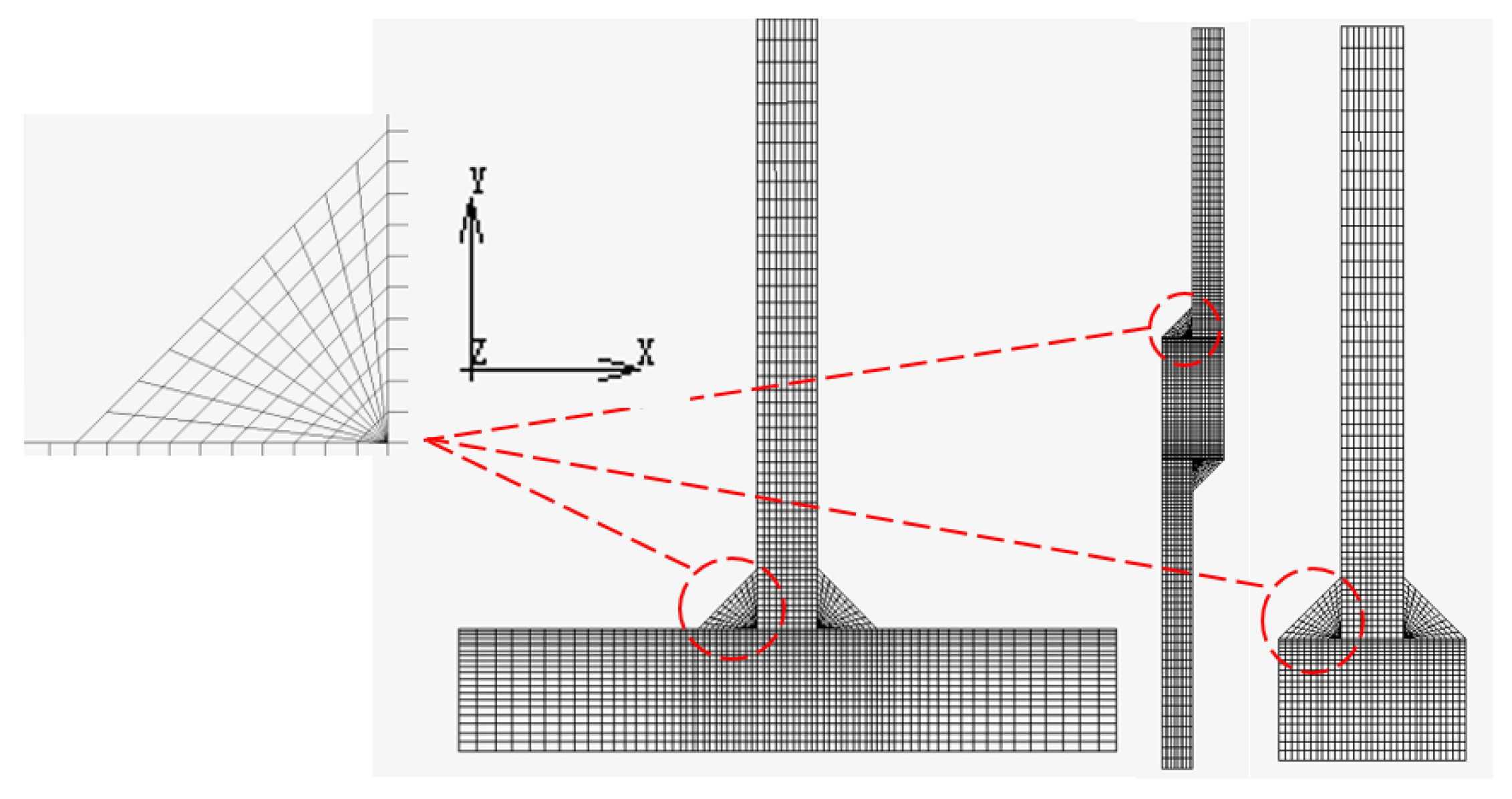
The linear elastic FE analysis was carried out using MARC 2017 (MacNeal-Schwendler Corporation, Los Angeles, CA, USA). Figure 1 shows the 2-D plane strain FE models. Only half of the T joint and the double-welded lap joint needed to be analyzed due to the symmetry. The total number of elements and nodes employed in the calculations of each situation were 2100 and 2230, 2000 and 2180, 1300 and 1421 for a T joint, a single-welded lap joint, and a double-welded lap joint, respectively. The consistency of Young’s modulus (200 GPa), the Poisson ratio (0.3), the convergence tolerance (0.1 of relative displacement), the thickness of the model (1 mm), the applied shear stress on the top (0.4 MPa), the displacement constraint (nodes on symmetric section fixed), the fillet weld sizes (5 mm), the thickness of the vertical plate (5 mm), the distance between the horizontal weld leg and the symmetric section (10 mm), the distance between the horizontal weld leg and the top (50 mm), and the meshing of the weld should be noted because it is more important than the accuracy of each FE model here.
2.2. Welding Procedure
A single lap joint was chosen for experimental verification. HSLA steel GB/T 16270:2009 HQ785 (Wuhan Iron and Steel Group Company, Wuhan, China) was used as the base metal, AWS A5.28:2005 ER110S-G (diameter 1.2 mm) (Harbin Well Welding Company Limited, Harbin, China) as the equalmatched filler material, and AWS A5.18:2005 ER70S-6 (diameter 1.2 mm) (Harbin Well Welding Company Limited, Harbin, China) as the undermatched filler material. The mechanical properties of these materials are shown in Table 1.
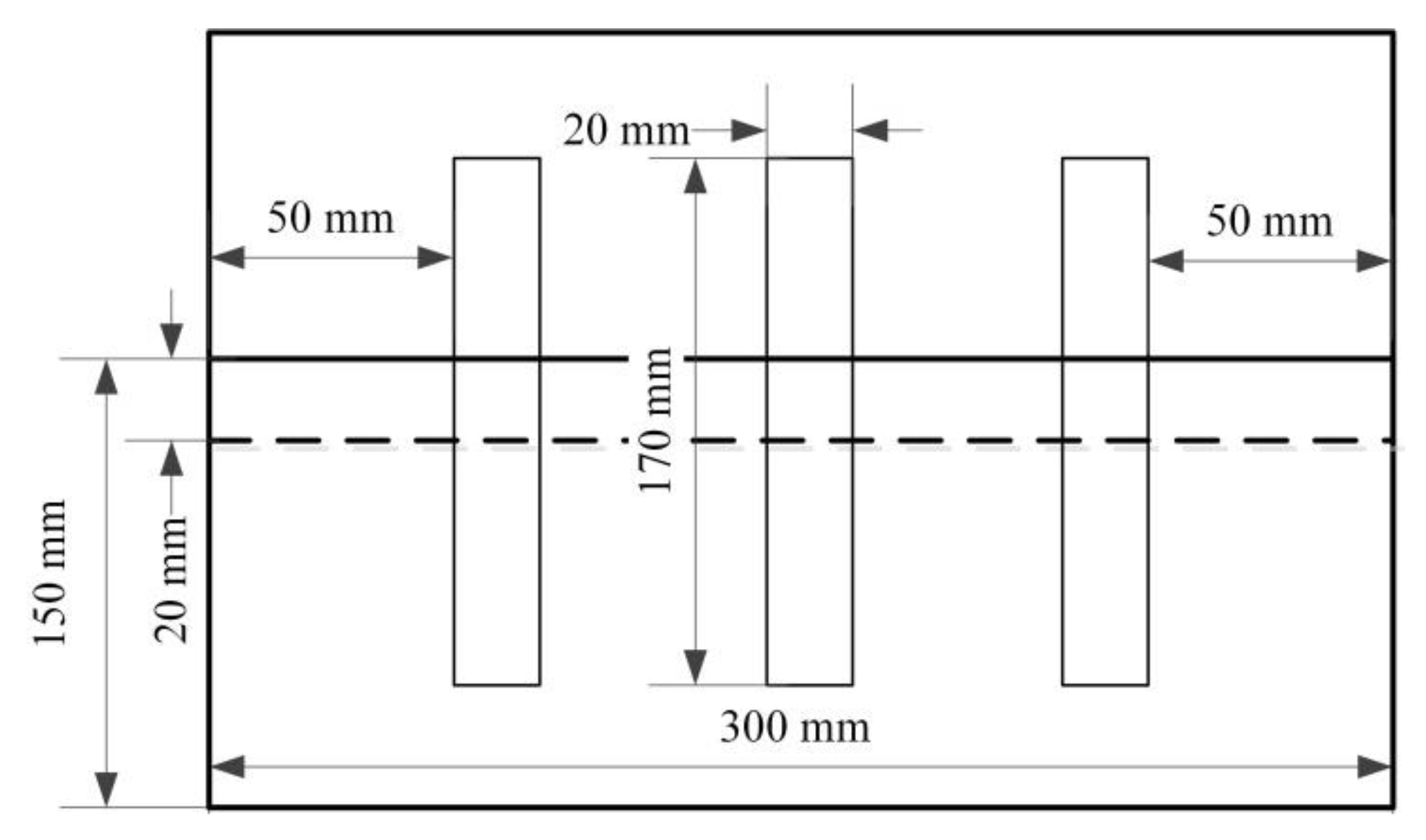
A welding process was applied to the test plates (10 mm thick) shown in Figure 2. An NBC500 inverter digital welder (Shandong Aotai Electric Co., Ltd. Jinan, China) was used as the welding machine. The operating temperature was 20 °C. The specific welding procedure and corresponding parameters are shown in Table 2.
2.3. Experimental Testing
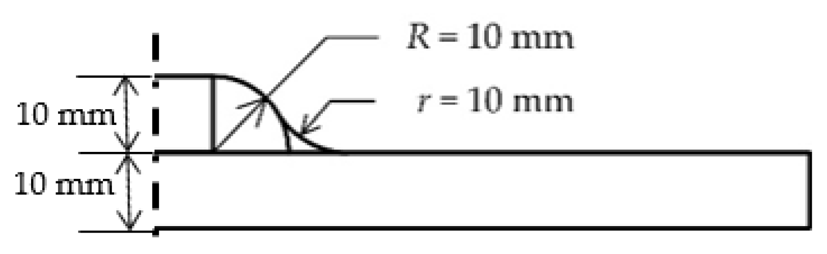
The bending specimen was taken perpendicular to the welding direction, as shown in Figure 2. The throat depth of the undermatched joint was 10 mm. An arc with a radius of 10 mm was used to eliminate the stress concentration of the weld toe. The weld geometric parameters of the ELCC joint are shown in Figure 2 and Figure 3. The same shape was used in the equalmatched joint to exclude the influence of the difference in Section 1. The dimensions of the base metal specimen were 170 mm × 20 mm × 10 mm.
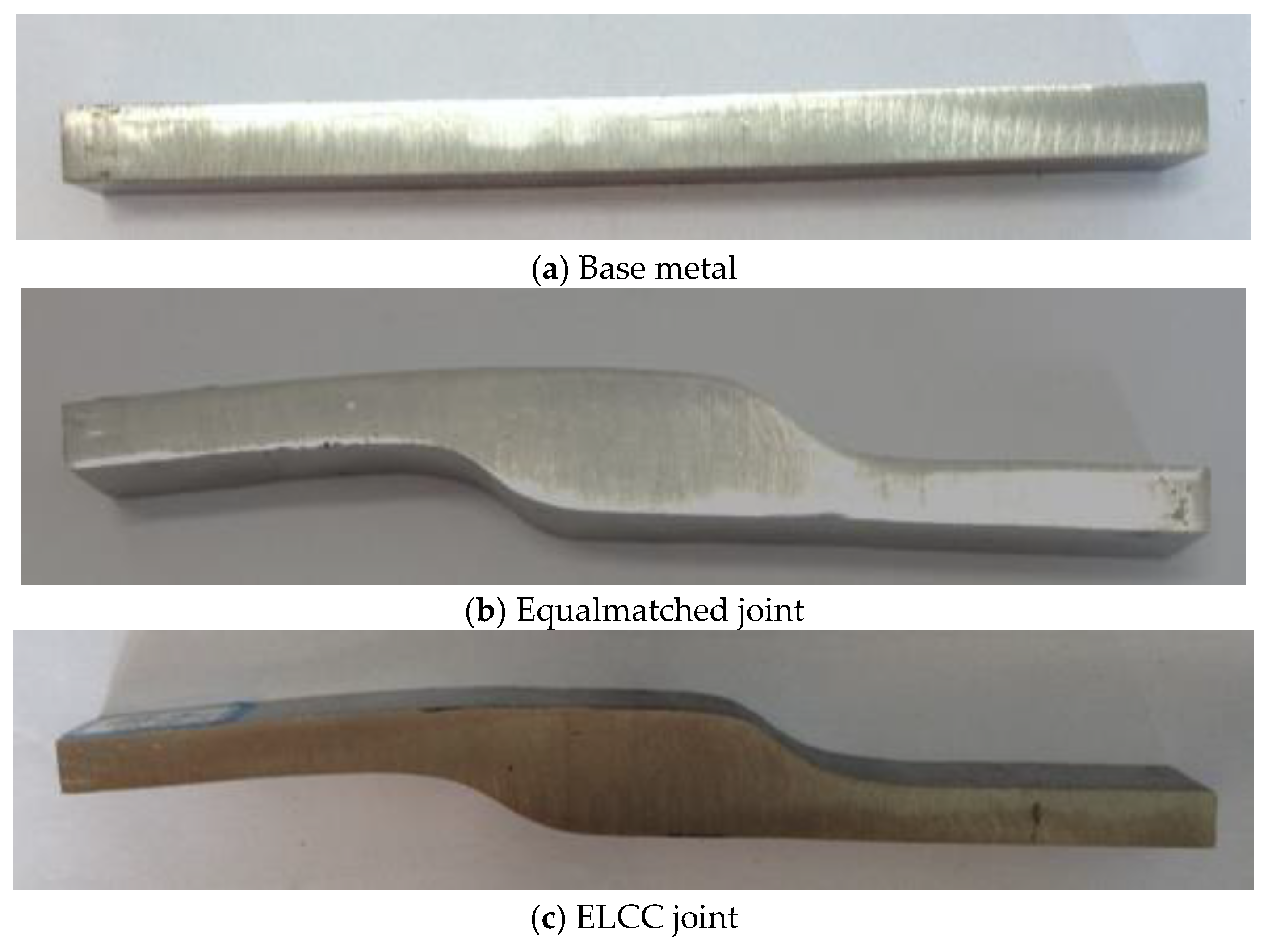
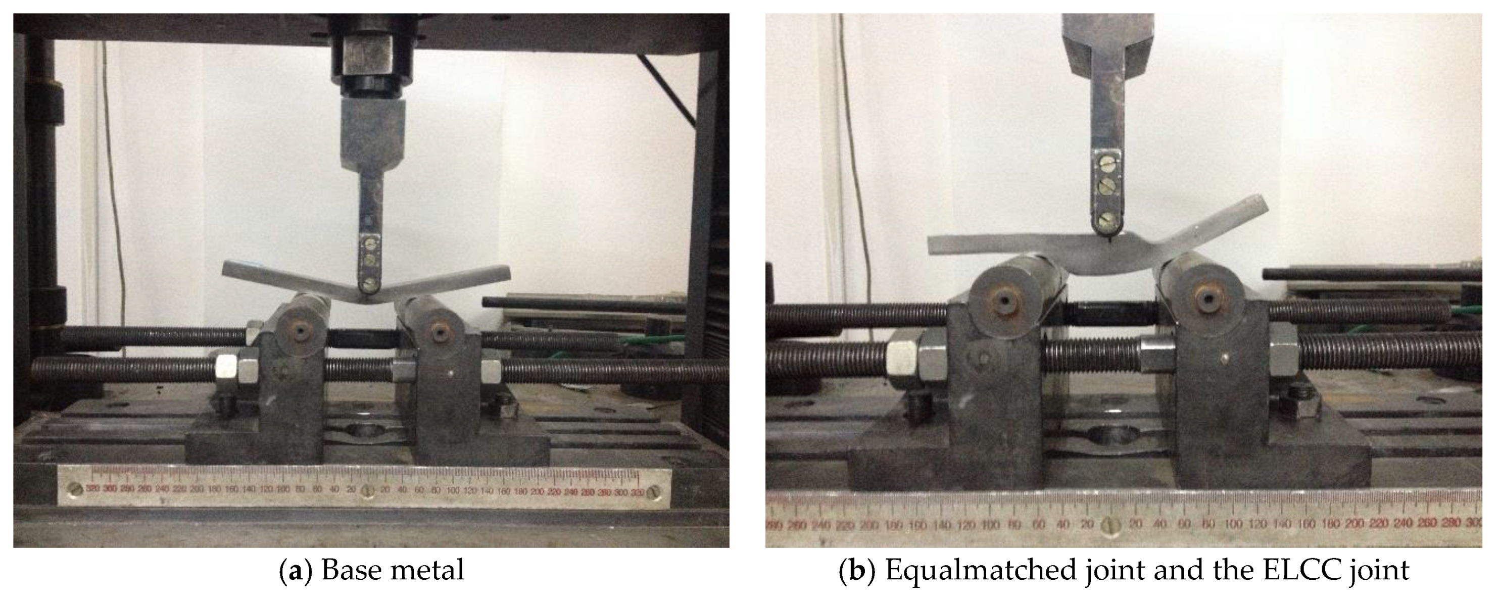
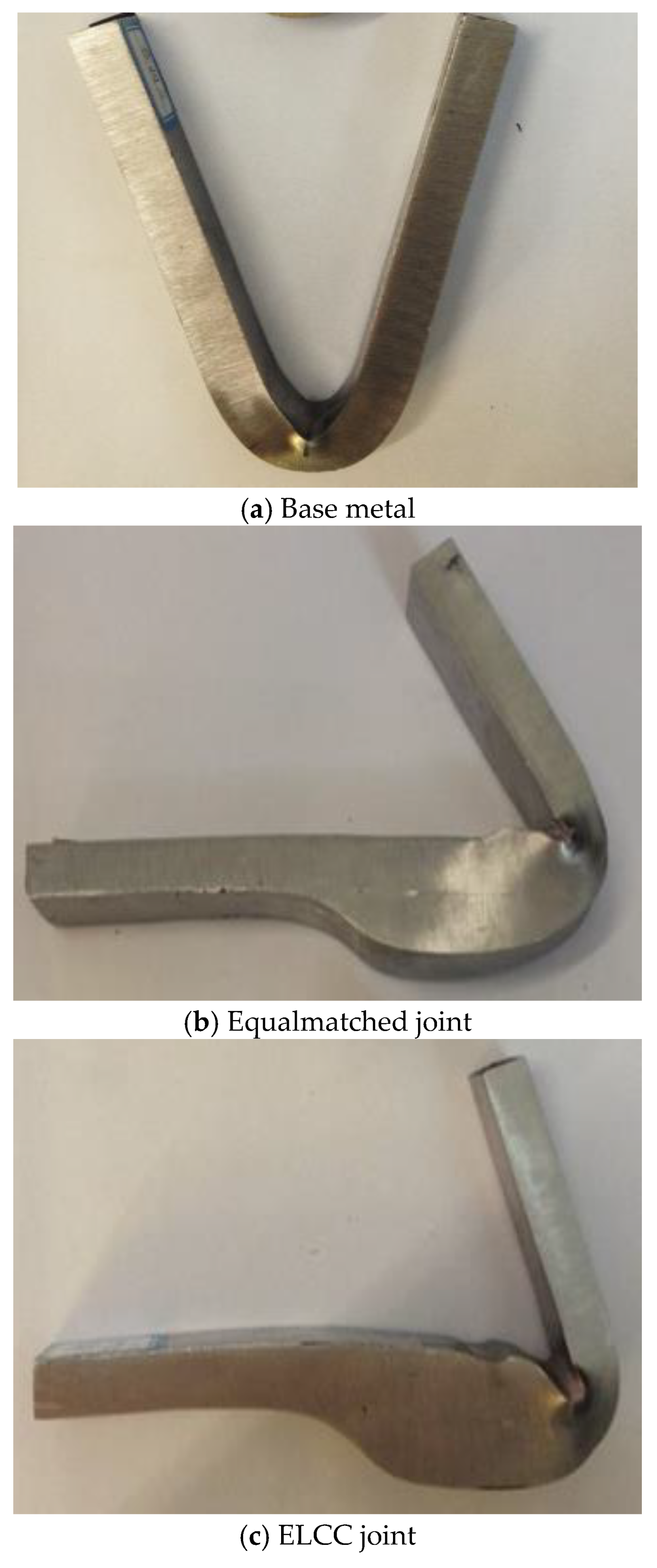
The wire-cutting and grinding were performed to obtain the designed shape. The prepared specimens are shown in Figure 4. Bending tests were conducted using an electron universal testing machine (CSS44300, Sinotest Equipment Company Limited, Changchun, China), as shown in Figure 5. According to ISO 5173:2000, the diameters of the supporting roller and the press roller were 30 mm and 10 mm, respectively, while the span was 2l = 80 mm. The test temperature was 20 °C and the loading rate was 2 mm/min. There were no specific standards for single-welded lap joint under out-of-plane bending to follow; however, for convenience of comparison, the experiment was conducted and recorded in the same manner as that of the base metal, where the ELCC joint and the equalmatched joint were affected by shear equally. Different supporting rollers (with the diameter of 30 mm and 20 mm, respectively) were once used to eliminate the horizontal components of the bending force but failed because the deformation of the lap joint became asymmetrical as the experiment went on.
3. Results and Discussion
3.1. Establishing the Strength Calculation Method of a Lap Joint under Out-of-Plane Bending
The theoretical derivation of the strength calculation method is very difficult because of the characteristics of the lap joint. This work took advantage of the similarity of a lap joint to a T joint, whose strength calculation method is prescribed.
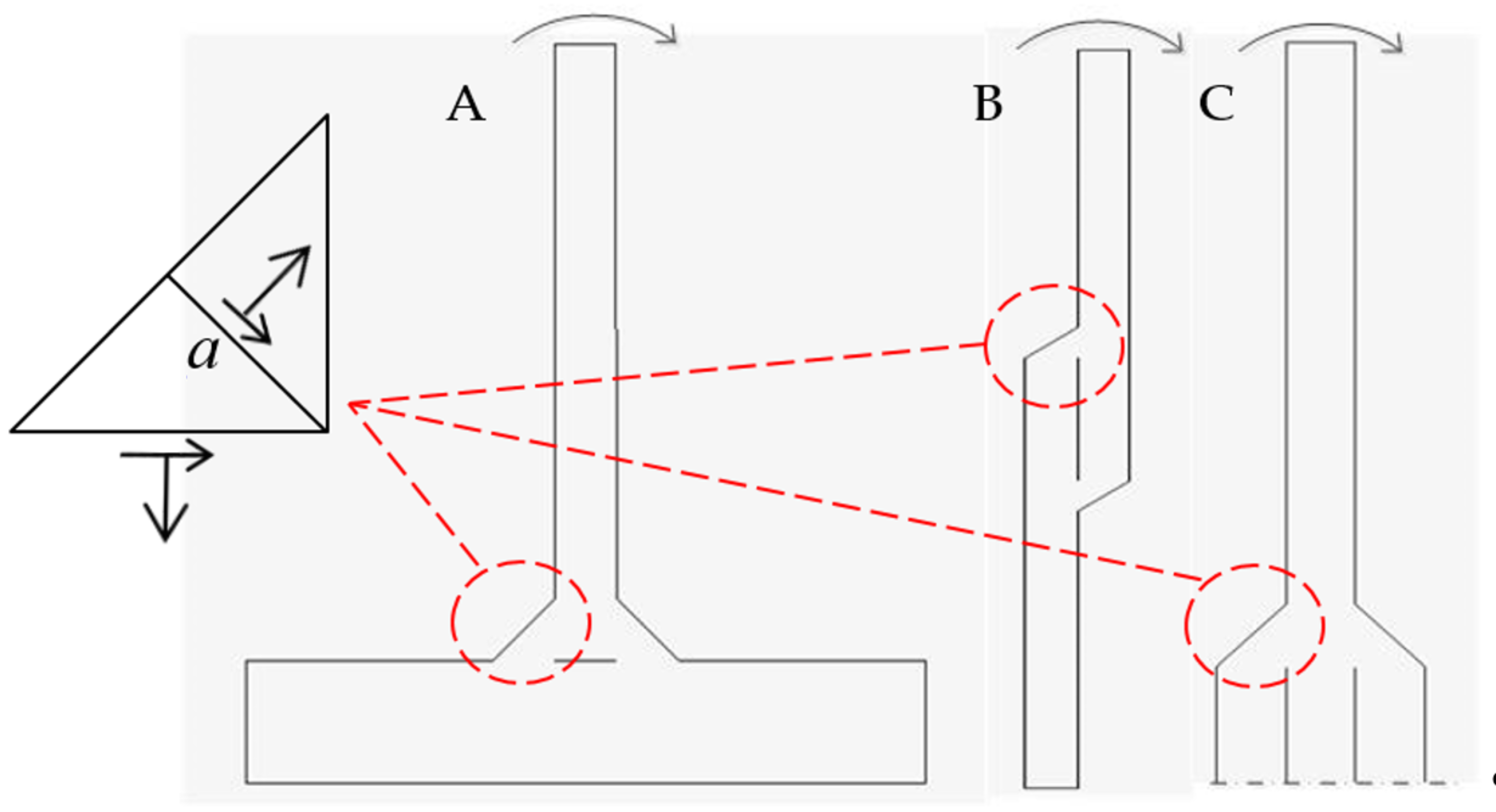
As shown in Figure 6, a T joint (A), a single-welded lap joint (B), and a double-welded lap joint (C) are three of the situations involving front fillet welds that bear out-of-plane bending. These three situations are physically similar in that the load on the edge of the weld must be transmitted by the welding throat. Thus, the load-carrying characteristics of these three situations should be similar.
3.1.1. The Mechanical Similarity Shown by FE Results
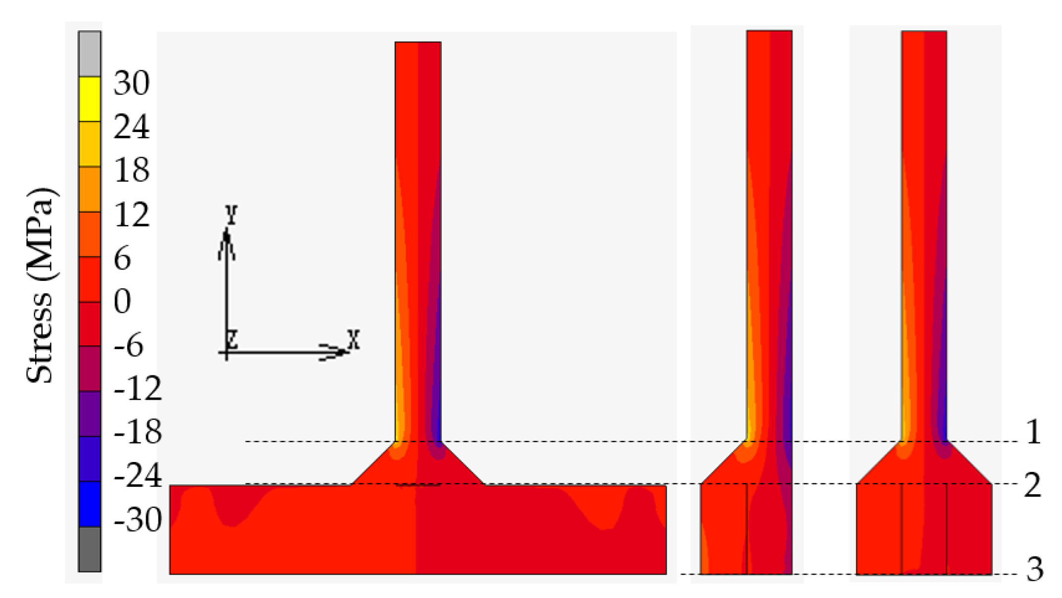
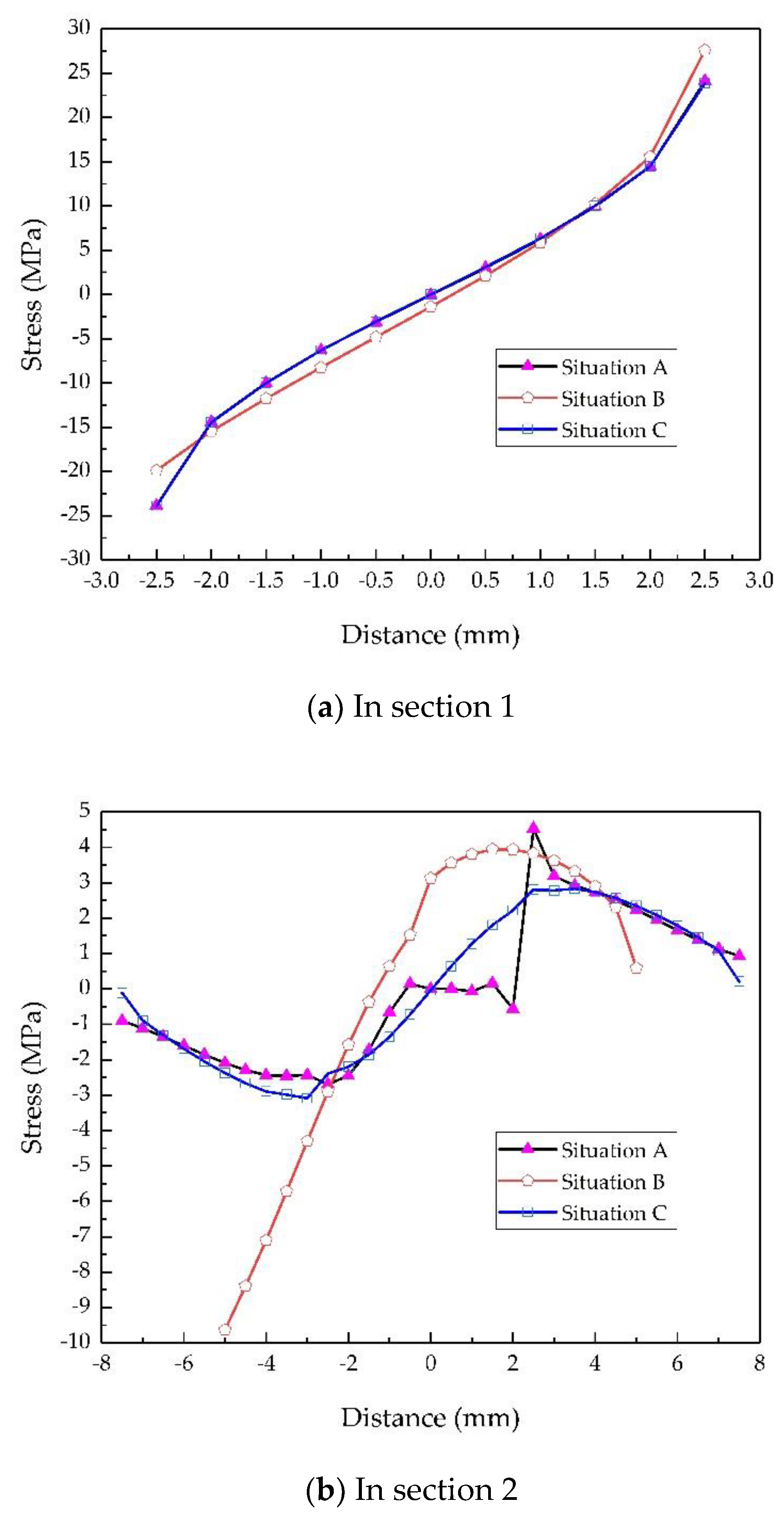
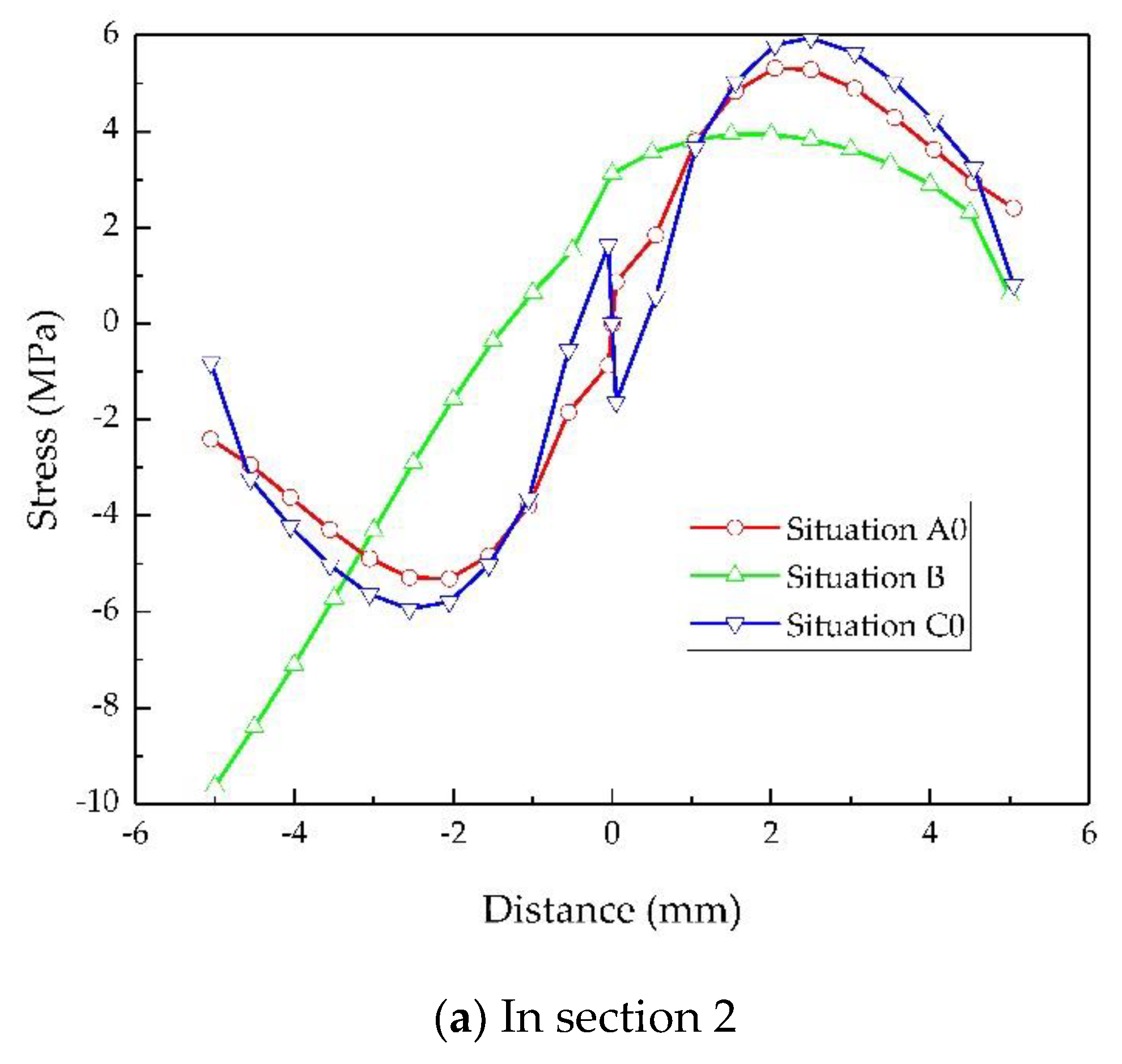
The stresses in the vertical direction are shown in Figure 7, and the enlarged view of the stretched side of the welds are shown in Figure 8. A high degree of similarity is observed, particularly between situations A and C. For further quantitative analysis, the stress distribution on sections selected in Figure 7 is given in Figure 9. The center of each section is located at x = 0.
As shown in Figure 9a, the curve of situation A’s section 1 and that of situation C’s section 1 coincide with each other, i.e., the stress distributions of situations A and C on section 1 are exactly the same, and the difference from that of situation B is very slight. If the stress in the vertical plate, which has little relation to the LCC of the weld, is ignored, it can be considered that the stress distributions of situations A and C in Section 2 are basically identical, while that of situation B is distinctive, as Figure 9b shows. Furthermore, the average stress of the stretched side of the weld was 2.29 MPa for situation A, 3.18 MPa for situation B, and 2.06 MPa for situation C. The load transmitted by the weld in situation C differed by only 10% from that in situation A, and it should be emphasized that the load in situation C was lower. Therefore, the load-carrying characteristics of the double-sided lap and T joint were basically the same; thus, their strength calculation methods should be the same. The average stress of situation B was significantly greater than that of situation A. Furthermore, as shown in Figure 9c, the stress distribution in section 3 was also significantly different from that of situation C.
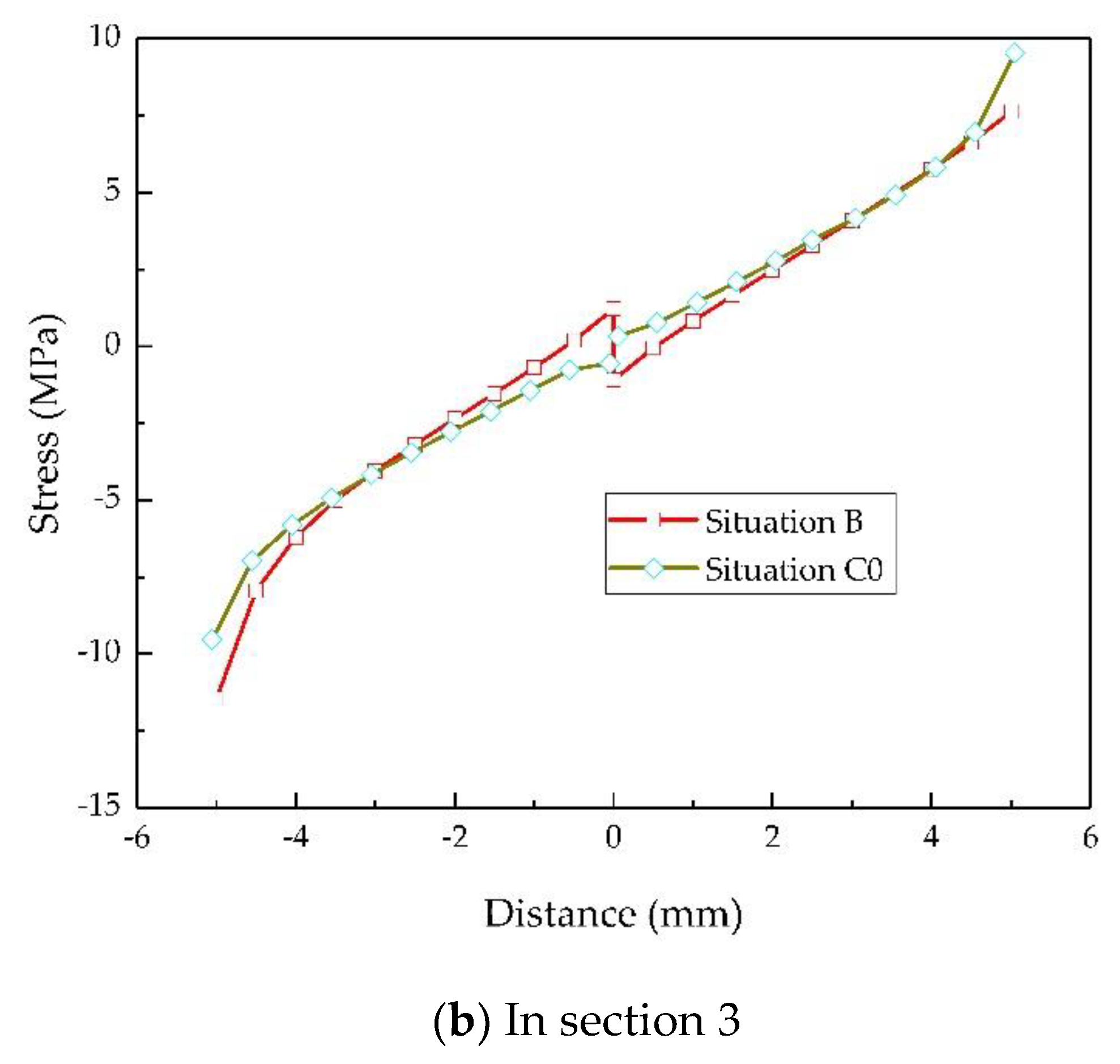
Noticing the symmetry of the stress distribution on Section 3, as shown in Figure 9c, the weld transmitted half of the initial load, and an imaginary mirror image of the weld is used to replace the vertical plate of single welded lap joint such that the obtained physical model was similar to situations A and C when the thickness of the vertical plate was 0 (situations A0 and C0). A value of t = 0.1 mm was used to approximate 0 to accomplish the FE analysis of situations A0 and C0. The obtained result is shown in Figure 10. The stress distributions of all situations in both sections 2 and 3 tended to be the same, as seen by comparing Figure 9b with Figure 10a and Figure 9c with Figure 10b. Furthermore, the average stress of the stretched weld on section 2 was 3.64 MPa for situation A0 and 3.48 MPa for situation C0. The load transmitted by the weld in situation B was 12.6% lower than that in situation A0 and 8.6% lower than that in situation C0. Therefore, their load-carrying characteristics were basically the same and their strengths could be calculated similarly.
In fact, the joints may also work in an elastoplastic or plastic state. However, this will not change their physical and mechanical similarity. Take the plastic state for example, where the plastic moment limits transmitted by the stretched weld of situations A and C were the same (Lσy × 50 mm2, where L represents the length of the weld, and σy represents the yield strength of the filler material), and so were those of situations A0, B, and C0 (Lσy × 25 mm2).
3.1.2. The Strength Calculation Method
The strength of a T joint fillet weld can be calculated using the following equation [26]:
where M represents the value of the out-of-plane bending moment, a represents the throat depth, and t represents the thickness of the vertical plate.
Based on the physical and mechanical similarity to a T joint, the strength of a double-sided lap fillet weld can be calculated according to Equation (1); the strength of a single lap fillet weld can also be calculated according to Equation (1) (t = 0):
3.2. Experimental Results
3.3. Application in the Prediction of Failure and the LCC of a Lap Joint
As shown in Figure 13, section 1 (the section with the weld throat) and section 3 are possible failure locations of a lap joint subjected to bending loads.
In section 1, the bending moment can be calculated using:
in section 2 using:
and in section 3 using:
The maximum bending moment that section 1 can withstand is:
where for elastic analysis and for ideal elastic-plastic analysis, and represents the yield strength of the base metal.
Thus, based on Equation (3), the maximum bending force that the joint can withstand is:
For a single lap joint, according to Equation (2), the maximum bending moment that the section of a weld throat can withstand, i.e., the maximum bending moment of section 2 is:
and for a double-welded lap joint, according to Equation (1), is:
where represents the yield strength of the filler material.
Thus, based on Equation (4), the maximum bending force on Section 2 is:
The maximum bending moment that Section 3 can withstand is:
where g = 4 for a single lap joint and g = 8 for a double-welded lap joint.
Thus, based on Equation (5), the maximum bending force on Section 3 is:
The joint will fail at the section with the smallest value of the maximum bending moment. For a traditionally designed lap joint, , , , and ; then, when or when . This means that an equalmatched lap joint designed according to traditional standards will not fail at the section of the weld throat, which is consistent with the facts. If l ≤ g(l − d − k), then , the joint will fail in section 1, and the LCC of the joint is times that of the base metal; else, , the joint will fail in section 3, and the LCC of the joint is g times that of the base metal.
As the bending test results show, the average F of the joint was about 1.93 times that of the base metal and 96.33% of the theoretical prediction. The slight dissimilarity was due to stress concentration caused by the shape mutation and processing marks at the weld toe. It should be note that the inequality is impossible here: even if , where the joints should fail in the section of weld throat, which is decidedly different from the experimental result showing that the joint fails in section 1. The reason for this phenomenon was the extra aE of the equalmatched joint and the metallurgical strengthening of the ELCC joint [18].
3.4. Application in the ELCC Design of an Undermatched Lap Joint
According to the thought of ELCC [27,28], considering the characteristics of a lap joint under out-of-plane bending, the LCC of the undermatched joint (MU) should be no lower than that of the traditionally designed equalmatched joint (ME):
MU ≥ ME.
For a single lap joint, according to Equation (2):
where represents the shear strength of the undermatched filler material, aU represents the throat depth of the undermatched joint, represents the shear strength of the equalmatched filler material, aE represents the throat depth of the equalmatched joint, and represents the matching ratio.
For a double-welded lap joint, according to Equation (1):
Equations (15) and (17) are the realizing conditions of ELCC for a single lap joint and a double-welded lap joint, respectively. For a traditionally designed lap joint with , Equations (15) and (17) can be rewritten as:
The maximum of aU is t; therefore, the minimum matching ratio is 0.5 for a single lap joint and 0.6 for a double-welded lap joint.
The matching ratio of the shear strength was assigned using the value for the yield strength. According to Equation (18), aU = 9.88 mm, and for the convenience of processing and manufacturing, 10 mm was adopted. The average F of an ELCC joint was 96.90% of an equalmatched joint, even if aE has been enlarged. The similarities between an ELCC joint and an equal-matched joint in LCC (F) illustrate that the ELCC design method proposed here is reasonable and feasible.
4. Conclusions
In order to improve the LCC of an undermatched lap joint under out-of-plane bending, this work established a strength calculation method for a lap joint and then developed an undermatched lap joint design based on the principle of ELCC. The specific conclusions are listed below.
(1) Through linear elastic FE analysis, the similarity of a T joint, a single-welded lap joint, and a double-welded lap joint in terms of load-carrying characteristics was verified; thus, the weld strength calculation method of a lap joint under out-of-plane bending was proposed.
(2) The failure and LCC of a lap joint under out-of-plane bending was discussed. The maximum bending force on different sections was calculated and the failure location was predicted. The results agreed well with those of a lap joint designed according to traditional standards.
(3) The concept of ELCC for a lap joint under out-of-plane bending was given, i.e., the LCC of an undermatched joint was equal to that of a traditionally designed equalmatched joint. The realizing condition of ELCC was put forward.
(4) A single lap joint was chosen for the experimental verification, where HQ785 as the base metal, ER110S-G as the equalmatched filler material, and ER70S-6 as the undermatched filler material were used. The bending force limit of an ELCC joint was 93.35% of the theoretical prediction and 96.90% of an equalmatched joint. The results show that the weld strength calculation method and the ELCC design method proposed in this study are reasonable and feasible.
Author Contributions
J.G. and J.W. performed the experiments; J.G., Z.D. and H.F. analyzed the data; J.G. undertook the FE analysis and wrote and revised the paper. All authors have read and agreed to the published version of the manuscript.
Funding
This research received funding from the National Natural Science Foundation of China (no. 51875131).
Institutional Review Board Statement
Not applicable.
Informed Consent Statement
Not applicable.
Data Availability Statement
The data presented in this study are available on request from the corresponding author. The data are not publicly available due to privacy.
Acknowledgments
The authors are grateful to scholars and friends for their help in accomplishing the work.
Conflicts of Interest
The authors declare no conflict of interest.
References
- Gao, B.; Lai, Q.; Cao, Y.; Hu, R.; Xiao, L.; Pan, Z.; Liang, N.; Li, Y.; Sha, G.; Liu, M.; et al. Ultrastrong low-carbon nanosteel produced by heterostructure and interstitial mediated warm rolling. Sci. Adv. 2020, 6. [Google Scholar] [CrossRef] [PubMed]
- Zhao, J.W.; Jiang, Z.Y. Thermomechanical processing of advanced high strength steels. Prog. Mater. Sci. 2018, 94, 174–242. [Google Scholar] [CrossRef]
- Ding, R.; Yao, Y.J.; Sun, B.H.; Liu, G.; He, J.G.; Li, T.; Wan, X.H.; Dai, Z.B.; Ponge, D.; Raabe, D.; et al. Chemical boundary engineering: A new route toward lean, ultrastrong yet ductile steels. Sci. Adv. 2020, 6. [Google Scholar] [CrossRef] [Green Version]
- Ran, M.M.; Sun, F.F.; Li, G.Q.; Wang, Y.B. Mechanical properties of mismatched high strength steel butt joints with three softened/hardened strength distribution patterns. Thin Wall. Struct. 2020, 146. [Google Scholar] [CrossRef]
- Shi, R.; Ma, Y.; Wang, Z.; Gao, L.; Yang, X.-S.; Qiao, L.; Pang, X. Atomic-scale investigation of deep hydrogen trapping in NbC/α-Fe semi-coherent interfaces. Acta Mater. 2020, 200, 686–698. [Google Scholar] [CrossRef]
- Breen, A.J.; Stephenson, L.T.; Sun, B.H.; Li, Y.J.; Kasian, O.; Raabe, D.; Herbig, M.; Gault, B. Solute hydrogen and deuterium observed at the near atomic scale in high-strength steel. Acta Mater. 2020, 188, 108–120. [Google Scholar] [CrossRef]
- Robertson, I.M.; Sofronis, P.; Nagao, A.; Martin, M.L.; Wang, S.; Gross, D.W.; Nygren, K.E. Hydrogen Embrittlement Understood. Metall. Mater. Trans. A 2015, 46, 2323–2341. [Google Scholar] [CrossRef] [Green Version]
- Świerczyńska, A.; Landowski, M. Plasticity of Bead-on-Plate Welds Made with the Use of Stored Flux-Cored Wires for Offshore Applications. Materials 2020, 13, 3888. [Google Scholar] [CrossRef]
- Tomków, J.; Fydrych, D.; Rogalski, G. Role of Bead Sequence in Underwater Welding. Materials 2019, 12, 3372. [Google Scholar] [CrossRef] [Green Version]
- Gáspár, M.; Sisodia, R. Improving the HAZ toughness of Q plus T high strength steels by post weld heat treatment. Iop Conf. Ser. Mater. Sci. 2018, 426. [Google Scholar] [CrossRef]
- Loureiro, A.J.R. Effect of heat input on plastic deformation of undermatched welds. J. Mater. Process. Tech. 2002, 128, 240–249. [Google Scholar] [CrossRef] [Green Version]
- Heinz, D.; Richter, B.; Weber, S. Application of advanced materials for ship construction—Experiences and problems. Mater. Corros. 2000, 51, 407–412. [Google Scholar] [CrossRef]
- Magudeeswaran, G.; Balasubramanian, V.; Reddy, G.M. Effect of welding processes and consumables on high cycle fatigue life of high strength, quenched and tempered steel joints. Mater. Des. 2008, 29, 1821–1827. [Google Scholar] [CrossRef]
- Hao, S.; Schwalbe, K.H.; Cornec, A. The effect of yield strength mis-match on the fracture analysis of welded joints: Slip-line field solutions for pure bending. Int. J. Solids Struct. 2000, 37, 5385–5411. [Google Scholar] [CrossRef]
- Tuma, J.V.; Sedmak, A. Analysis of the unstable fracture behaviour of a high strength low alloy steel weldment. Eng. Fract. Mech. 2004, 71, 1435–1451. [Google Scholar] [CrossRef]
- Lukács, J.; Dobosy, A. Matching effect on fatigue crack growth behaviour of high-strength steels GMA welded joints. Weld. World 2019, 63, 1315–1327. [Google Scholar] [CrossRef] [Green Version]
- Peter, C.; Mikael, M.; Mattias, N.; Svante, T. Undermatching Butt Welds in High Strength Steel, IABSE annual meeting and symposium. In Proceedings of the IABSE Symposium, Bangkok, Thailand, 9–11 September 2009. [Google Scholar]
- Rodrigues, D.M.; Menezes, L.F.; Loureiro, A. Modelling the effect of HAZ undermatching on the crack-tip stress distribution in idealized welds. Int. J. Mech.Sci. 2004, 46, 1481–1488. [Google Scholar] [CrossRef] [Green Version]
- Baud, R.V. Fillet profiles for constant stress. Prod. Eng. 1934, 5, 133–134. [Google Scholar]
- Neuber, H. The flat bar subjected to tensile loading with an optimum transition in section. Forsch Ing. 1969, 35, 29–30. [Google Scholar] [CrossRef]
- Schnack, E.; Weikl, W. Shape optimization under fatigue using continuum damage mechanics. Comput. Aided Des. 2002, 34, 929–938. [Google Scholar] [CrossRef]
- Mattheck, C. Teacher tree: The evolution of notch shape optimization from complex to simple. Eng. Fract. Mech. 2006, 73, 1732–1742. [Google Scholar] [CrossRef]
- Baptista, R.; Infante, V.; Branco, C.M. Study of the fatigue behavior in welded joints of stainless steels treated by weld toe grinding and subjected to salt water corrosion. Int. J. Fatigue 2008, 30, 453–462. [Google Scholar] [CrossRef]
- Yi, H.J.; Lee, Y.J.; Lee, K.O. TIG Dressing Effects on Weld Pores and Pore Cracking of Titanium Weldments. Metals 2016, 6, 243. [Google Scholar] [CrossRef] [Green Version]
- Mettanen, H.; Nykanen, T.; Skriko, T.; Ahola, A.; Bjork, T. Fatigue strength assessment of TIG-dressed ultra-high-strength steel fillet weld joints using the 4R method. Int. J. Fatigue 2020, 139. [Google Scholar] [CrossRef]
- Yaowu, S. Welding Structure, 3rd ed.; China Machine Press: Beijing, China, 2008; Volume 3. [Google Scholar]
- Wen, X.; Wang, P.; Dong, Z.B.; Liu, Y.; Fang, H.Y. Nominal Stress-Based Equal-Fatigue-Bearing-Capacity Design of under-matched HSLA Steel Butt-welded Joints. Metals 2018, 8, 880. [Google Scholar] [CrossRef] [Green Version]
- Wen, X.; Wang, P.; Dong, Z.B.; Fang, H.Y. A Fracture Mechanics-Based Optimal Fatigue Design Method of Under-Matched HSLA Steel Butt-Welded Joints with Imperfections. Appl. Sci. Basel 2019, 9, 3609. [Google Scholar] [CrossRef] [Green Version]
Figure 1.
2-D finite element (FE) models of the joints.

Figure 2.
Plate dimensions and the sampling method.

Figure 3.
The weld geometric parameters of equal load-carrying capacity (ELCC) joint.

Figure 4.
The prepared specimens.

Figure 5.
Bending test.

Figure 6.
Front fillet welds under out-of-plane bending.

Figure 7.
Distribution of the stress in the vertical direction.

Figure 8.
Stress distribution of the stretched side of the weld.

Figure 9.
Comparison of the stress distribution in certain sections.


Figure 10.
Comparison of the stress distribution in certain sections.


Figure 11.
The specimens after bending.

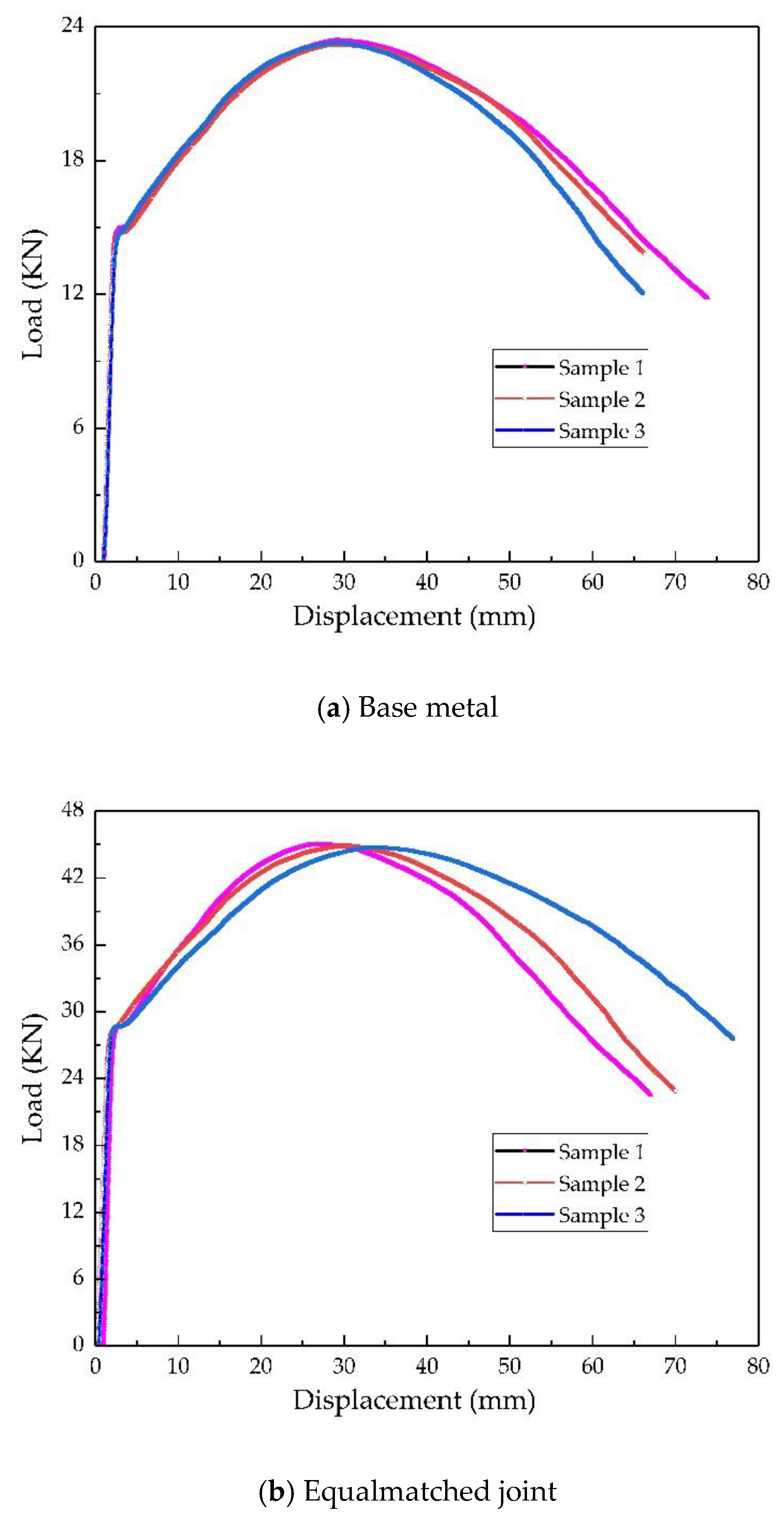
Figure 12.
The load-displacement curves.


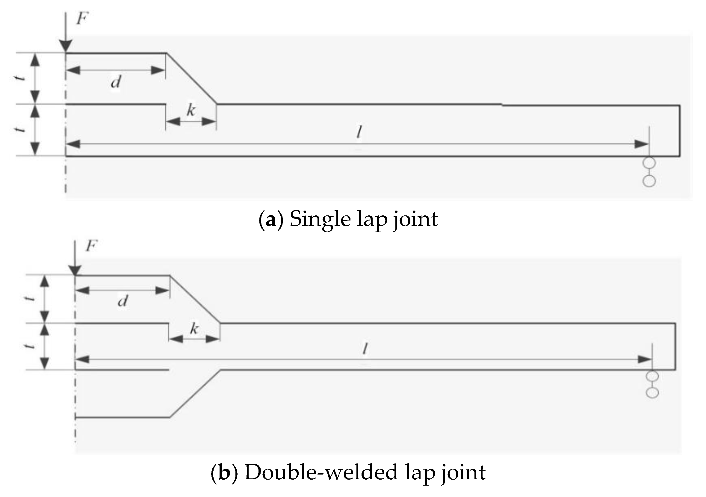
Figure 13.
Lap joint under out-of-plane bending.


Table 1.
Chemical composition (wt.%) and mechanical properties of materials.
| Materials | C | Si | Mn | Cr | Mo | Ni | Tensile Strength σu (MPa) | Yield Strength σy (MPa) | Elongation Rate A (%) |
|---|---|---|---|---|---|---|---|---|---|
| HQ785 | 0.10 | 0.20 | 1.41 | 0.56 | 0.33 | - | 840 | 790 | 18 |
| ER110S-G | 0.09 | 0.55 | 1.68 | - | 0.43 | 1.02 | 835 | 760 | 20 |
| ER70S-6 | 0.10 | 0.90 | 1.65 | - | - | - | 560 | 405 | 32 |
Table 2.
Welding procedure and the corresponding parameters.
| Joint Type | Welding Process | Current Type/Polarity | Welding Current (A) | Arc Voltage (V) | Welding Speed (mm/s) | Shielding Gas/Flow Rate (L/min) | Preheating Temperature (°C) |
|---|---|---|---|---|---|---|---|
| Equalmatched | MAG | DC/− | 270 | 30 | 5.5 | CO2/5 Ar/18 | 80 ± 5 |
| Undermatched | MIG | DC/− | 200 | 19 | 2 | Ar/13 | - |
Table 3.
Bending test results of the specimens.
| Sample Type | Base Metal | Equalmatched Joint | ELCC Joint | ||||||
|---|---|---|---|---|---|---|---|---|---|
| Sample No. | 1 | 2 | 3 | 1 | 2 | 3 | 1 | 2 | 3 |
| F (kN) | 23.38 | 23.22 | 23.29 | 45.02 | 44.88 | 44.77 | 44.96 | 44.06 | 41.48 |
| Average of F (kN) | 23.30 | 44.89 | 43.50 | ||||||
| Bending Angle (°) | 125 | 121 | 108 | ||||||
Publisher’s Note: MDPI stays neutral with regard to jurisdictional claims in published maps and institutional affiliations. |
© 2021 by the authors. Licensee MDPI, Basel, Switzerland. This article is an open access article distributed under the terms and conditions of the Creative Commons Attribution (CC BY) license (http://creativecommons.org/licenses/by/4.0/).
Share and Cite
MDPI and ACS Style
Guo, J.; Dong, Z.; Fang, H.; Wang, J. Strength Calculation and Equal Load-Carrying-Capacity Design of an Undermatched HSLA Lap Joint under Out-of-Plane Bending. Metals 2021, 11, 161. https://0-doi-org.brum.beds.ac.uk/10.3390/met11010161
AMA Style
Guo J, Dong Z, Fang H, Wang J. Strength Calculation and Equal Load-Carrying-Capacity Design of an Undermatched HSLA Lap Joint under Out-of-Plane Bending. Metals. 2021; 11(1):161. https://0-doi-org.brum.beds.ac.uk/10.3390/met11010161
Chicago/Turabian StyleGuo, Junli, Zhibo Dong, Hongyuan Fang, and Jiajie Wang. 2021. "Strength Calculation and Equal Load-Carrying-Capacity Design of an Undermatched HSLA Lap Joint under Out-of-Plane Bending" Metals 11, no. 1: 161. https://0-doi-org.brum.beds.ac.uk/10.3390/met11010161
Note that from the first issue of 2016, this journal uses article numbers instead of page numbers. See further details here.