1. Introduction
The search for materials that improve the existing performance is constantly evolving in various sectors. In this sense, current industry seeks to take advantage from the properties offered by both metal alloys and thermoset or thermoplastic composites, such as in the automotive sector in electric vehicles, the aeronautical sector in the reduction in aircraft weight or the naval sector [
1,
2,
3]. The need to satisfy the increasingly comprehensive requirements of the market has led to the search for ways to improve their properties through various means [
1].
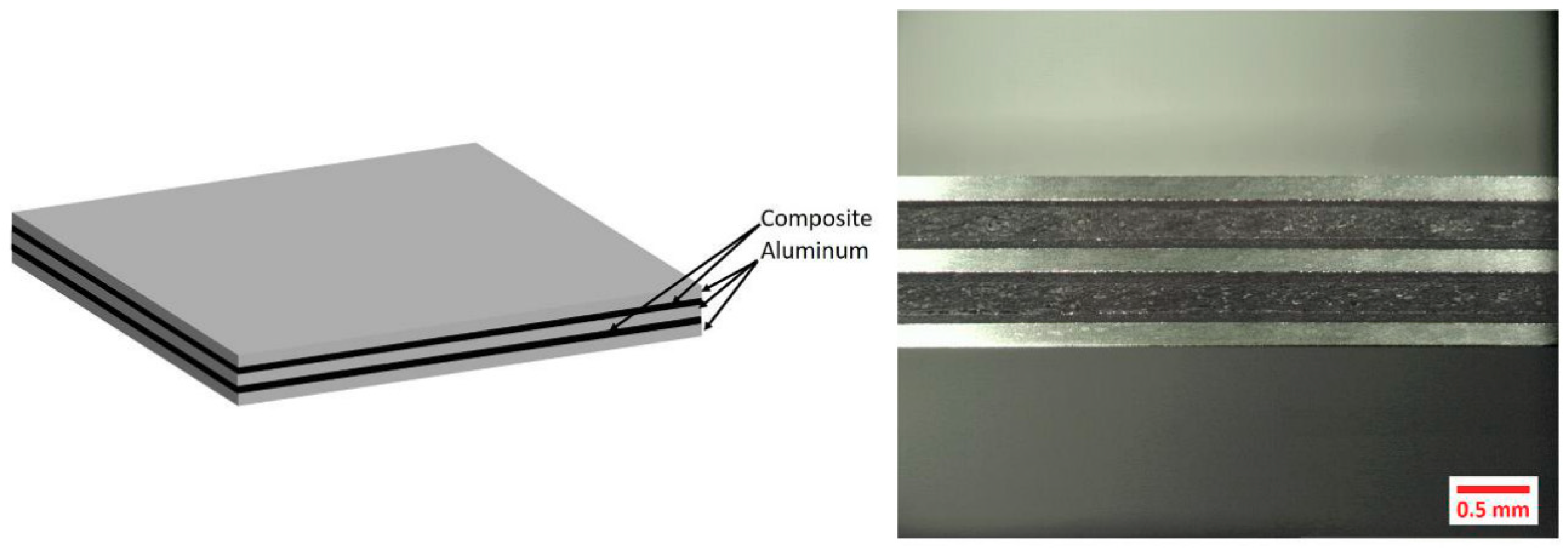
One way to take advantage of materials with different nature is the formation of a hybrid structures (
Figure 1). These structures are obtained by joining metal and composite sheets. In this way, the resistance of the fibers and the conformability of the metals are combined [
4,
5,
6,
7].
These structures stand out for having mechanical, physical, durability and cost advantages [
4]. However, these hybrid structures also have some disadvantages. Among them, the need to be manufactured by means of adhesives or thermal joints that ensure good insulation between the components stands out; this is mainly because the materials that make up the system may show a different electrochemical potential, which would lead to corrosion under specific environments.
Nevertheless, the joining of both materials into one is a great challenge due to the difficulties they present. Below are some techniques used in different studies focused on obtaining hybrid structures.
Bernd-Arno et al. [
9] explain a method for joining steel sheets and CFRPs (carbon fiber-reinforced polymers), and they indicate the need to avoid contact between both materials to prevent corrosion defects and to use tools with the ability to vary their temperature to perform the manufacturing process of the material as previously exposed.
At the same time, the performance of a surface texture can be fundamental for the correct joining of the materials. Klotzbach et al. [
10] propose the use of laser technology for the joining process between the metallic alloy and the composite material. Thus, laser can be used as a preliminary preparation in order to eliminate residues and improve the bonding area. In addition, it can generate a high intensity of radiation in local areas, which heats the metal by conduction, causing the melting of the thermoplastic matrix in contact with the material in order to make the joint.
On the other hand, Artaza et al. [
11] propose the use of abrasive water-jet machining (AWJM) to perform textures on steel surface sheets to improve the quality of the union between the metal and a composite layer. To do this, they join steel plates textured by this technology to three types of composite materials obtained by different manufacturing processes (infusion, prepreg and union by means of a structural adhesive). That research concluded by highlighting the importance of the realization of a proper textured surface to obtain high-quality bonding properties.
Nowadays, joining dissimilar materials is a challenge. Performing a correct surface preparation and selecting the appropriate technology for their union are two of the main research lines on this topic.
Since they are materials of a different nature, they present, at the same time, different defects when they have to be machined in order to give their final shape. This is a great challenge for the current industrial sector. As an example of previously described is the performance of drilling operations of hybrid structures in the aeronautical sector. The most commonly used configurations are “CFRP-Aluminum” [
1,
12] and “CFRP-Titanium” [
13,
14,
15]. The aeronautical sector, therefore, seeks to reduce time and costs by machining in a single step structural elements to be assembled by means of mechanical joining operations through rivets [
1,
16]. Thus, a need constantly arises to reduce the final weight of the structure which has increased the interest in adhesive joints compared to mechanical ones.
The strategic interest in this kind of material configuration is therefore denoted. However, these material configurations can receive different nomenclatures [
4].
FML (Fiber Metal Laminate): Overlay of low thickness sheets of metal alloys and unidirectional composite material stacked alternately. The union of both can be by mechanical or adhesive bonding. However, these materials can be made up of thin metal sheets and unidirectional fiber, the binder being a thermostable or thermoplastic polymer matrix [
17].
Stack: It refers to the arrangement of the materials when forming the joint. There are usually two plates that make up the structure; they are of equal or different thicknesses or even the same type of material [
18]. This nomenclature, as has been observed, is the most common nomenclature in current research.
Hybrid Structure: This is the nomenclature that has begun to be used in the last few years and that will be adopted throughout this research work. It refers to the union of a metallic alloy to a polymeric matrix composite material, which can be joined by means of an adhesive or thermal bond [
19].
2. Abrasive Water-Jet Machining
Non-conventional processes are currently attracting a lot of interest because they can provide a very high performance. The correct machining of different metal alloys and polymeric matrix composite materials has been one of the great challenges in recent years due to the characteristics mentioned above. These hybrid materials have been machined with different technologies, from conventional techniques in drilling and milling operations, to water- jet cutting processes and laser technologies.
Abrasive water-jet machining (AWJM) can be a very interesting choice in this context. Dr. Mohamed Hashish is considered as the father of this machining technology, who proposed a series of models and background on water-jet machining of metals [
20,
21,
22]. It is a flexible process, capable of achieving high productivity in the form of high material removal rates. In addition, it generates low machining forces and, especially, generates a very small temperature range compared to conventional processes. This is of great interest because it minimizes the probability of deterioration or degradation of the polymeric matrix of the composite material [
23]. From an environmental point of view, this process has high efficiency by using water at high pressure, that can be reused later, reducing its negative impact on the environment. Compared to conventional technologies, there is no physical tool, and there is much less wear on auxiliary elements, reducing process costs as it can be used over a wide range of materials with different machinability at the same time [
19]. In addition, metalworking fluids (MWF) are not required [
24].
Nevertheless, this technology has different defects associated with the process. The AWJM process generates regions with different surface quality depending on the thickness of the material. It also generates variations of kerf widths at the entrance and exit of the material in the form of conicity or taper angle, mainly caused by the dispersion of the kinetic energy of the water jet. These defects concern the micro and macro-geometric deviations of the final product. These variations are key parameters for the evaluation of the geometry within the design and assembly specifications.
Water-jet machining uses a mixture of fluid and solid particles that is accelerated and causes the deformation or removal of the target material on which it is impacted. The jet can be composed of any liquid, but for economic and environmental reasons, the liquid used is usually a mixture of water and air. The water, by presenting a higher density, applies a higher impact pressure during machining [
25,
26].
In this process, a third element consisting of small abrasive particles is added to the air and water flow. These can be of any material, shape or size, and must be harder than the material to be machined in order to remove it and cause as little damage as possible [
25,
27,
28]. These particles usually show irregular geometries and sharp edges. However, more rounded particles can be used which generate deformations and residual compressive stresses [
11].
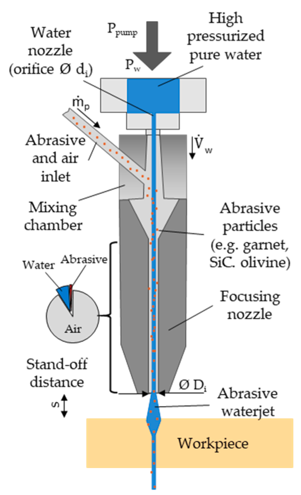
Abrasive particles are absorbed by the vacuum created in the mixing chamber, due to the pressure drop at the jet periphery caused by the acceleration of the water jet. In this chamber, the particles are mixed with the water jet at high speed and both are passed through a focusing nozzle, also called a mixing chamber, which is slightly larger in diameter than the hole through which the water passes before. This tube has homogenizing the fluid jet with the particles set as the main function (
Figure 2).
If the particles to be used have a reduced size and an irregular geometry with sharp edges, the impact speed they reach is very high, close to 1000 m/s [
30,
31], which allows these particles to penetrate into the material to be machined, generating a permanent crater [
25,
27]. It should be noted that abrasive particles may collide inside and reduce final size when mixed with water flow.
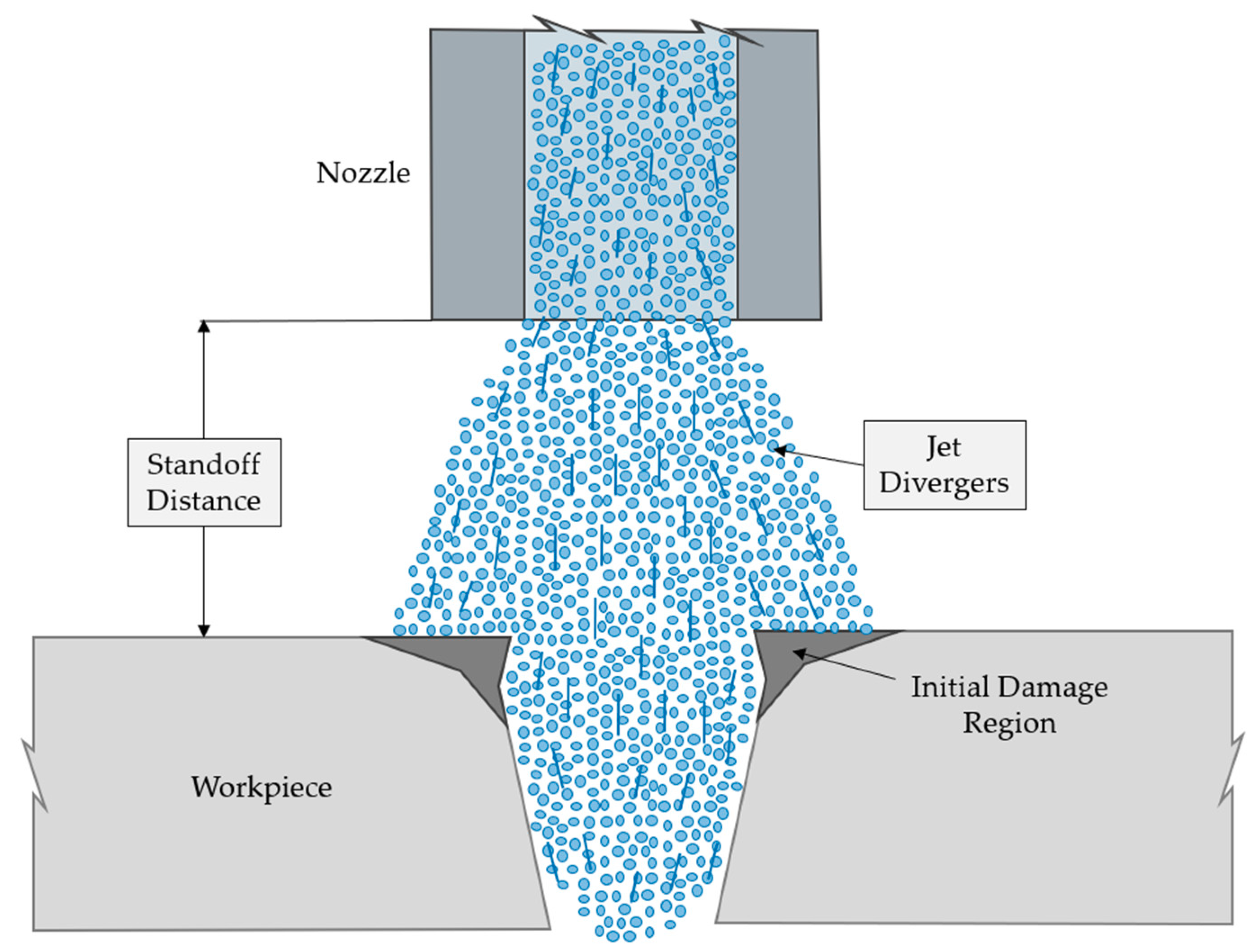
Finally, when they are ejected by the nozzle, the jet expands freely in a divergent way, reducing its power density and thus the machining capability if the distance between the nozzle and the material is very high [
32,
33,
34].
The removal of material during abrasive water-jet cutting is based on the continuous impact of solid particles on the material. This process can be divided into four sub-mechanisms in which abrasive particles erode the material surface: cutting, fatigue, melting, and brittle fracture [
35,
36]. These mechanisms do not act separately, but in combination. In this way, the final cuting effect is generated by the geometric superposition of craters formed by the particles that have impacted the material [
37,
38]. It is necessary to differentiate between the behavior of ductile materials and fragile materials, since due to their different properties they show different behaviors [
28,
39]. Ductile materials suffer plastic deformation during cutting, while brittle materials are subjected to cutting through fracture.
However, it is a process that can present a series of limitations. Due to the loss of kinetic energy during machining and the different machinability of the materials, various defects can occur. Regions of different surface quality have been detected in several investigations generating striations in the final region known as lag defect. At the same time, the resistance of the materials to be machined reduces the kinetic energy of the water jet. This produces a difference between the upper width of the cut and the lower width generating a defect known as taper angle. This defect is enhanced by the erosion effect of the abrasive particles in the initial moments. These produce a rounding on the edges, generating an area affected by erosion.
These defects will be discussed in the following sections, focusing on the material to be machined and the correct selection of cutting parameters.
3. Associated Defectology in AWJM: Cutting Geometry
As previously mentioned, abrasive water-jet machining is a highly flexible process that can achieve high performance in the form of high material removal rates compared to other conventional or traditional processes, such as milling [
40]. However, it has associated defects and issues that must be considered to generate an adequate cut to accommodate the final specifications.
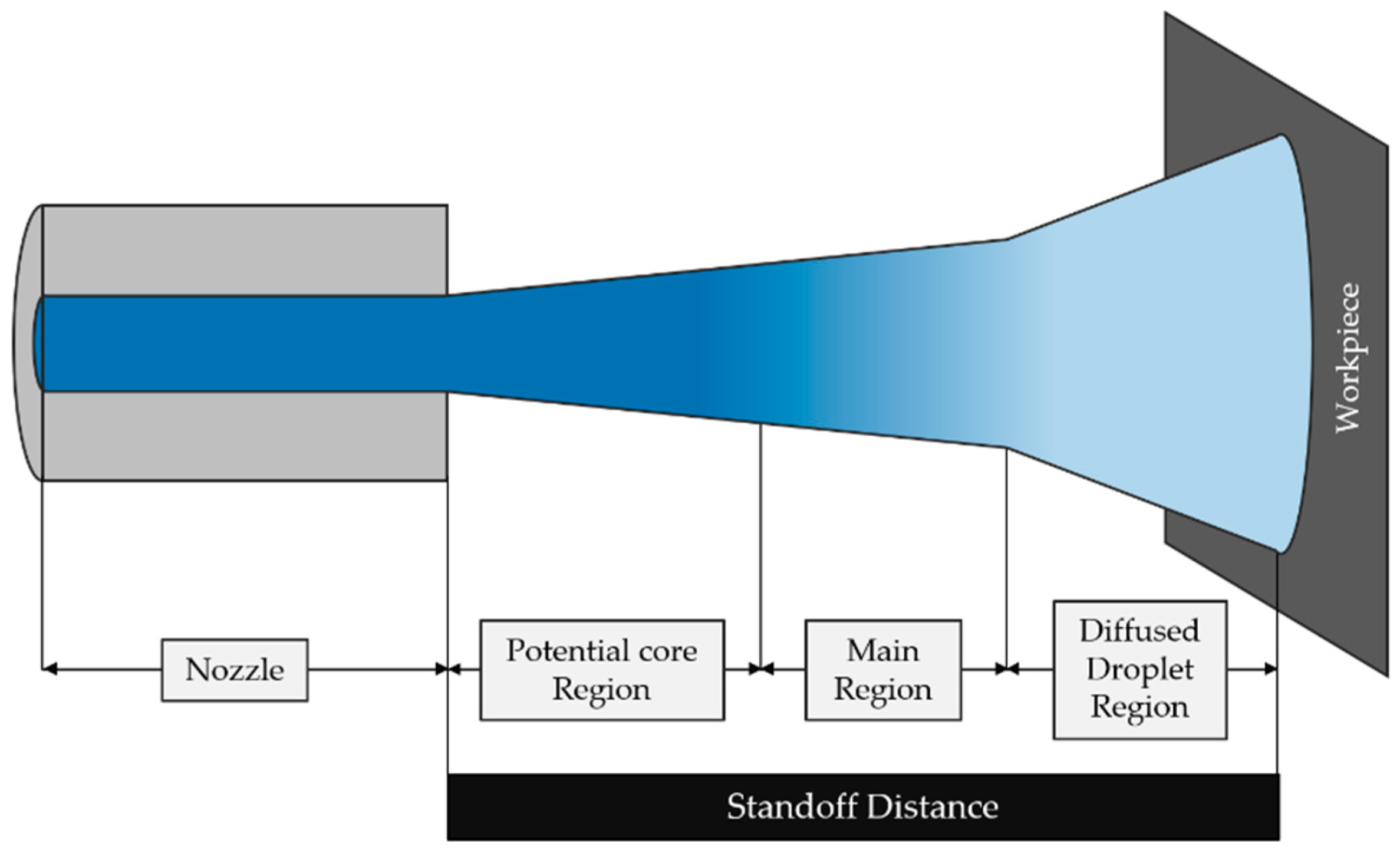
These defects are associated with the final geometry after the machining process. In comparison with conventional processes, the water jet is not a solid element. When it comes out of the nozzle it diverges until it comes into contact with the material. This divergence minimizes its kinetic energy, as detailed in
Figure 3.
This effect causes a decrease in the kinetic energy from the initial impacts against the target material. From this moment the flow of water and abrasive particles begins to erode the material until it is able to pass through it completely. Nevertheless, as it penetrates the material, the water jet itself continuously loses kinetic energy, causing the diameter of the water jet and the width of the machined material to be reduced in conical form.
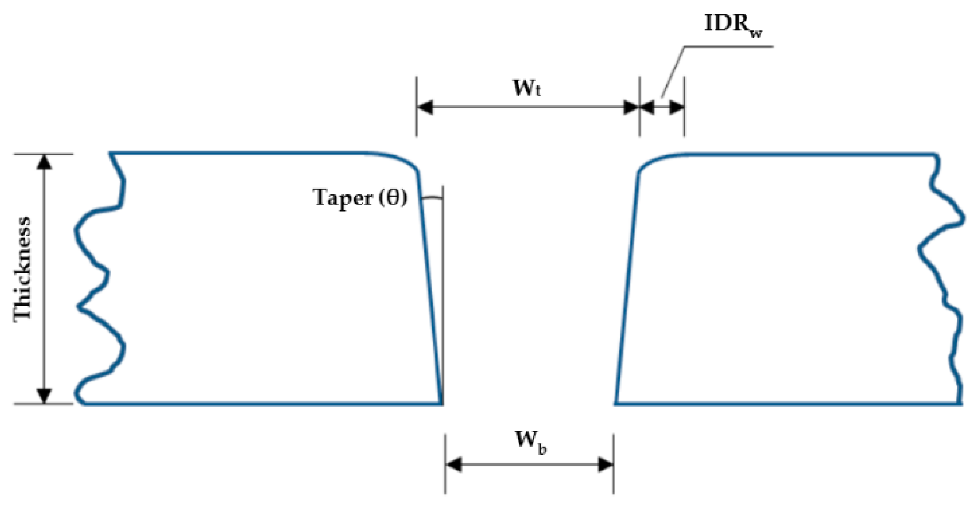
This effect produces the characteristic cutting geometry associated with the abrasive water-jet cutting process, referred to as taper cutting (
Figure 4). This geometry is usually characterized by three geometric factors: top width (
Wt), bottom width (
Wb) and the taper angle (
Φ).
All these geometrical factors define the geometry generated by this technology, which are directly associated with the previous selection of cutting parameters or input parameters: hydraulic pressure (P), traverse speed (TS), abrasive mass flow (f) and the distance between the nozzle and the upper surface of the material to be machined (d). Depending on the increase or decrease in these cutting parameters, the obtained cutting geometry will show a more pronounced conicity, or an almost perpendicular walls will be achieved with a minimum conicity.
In this way, the cutting geometry can be calculated in different ways. The first way consists of a ratio between the upper width and lower width (1). The closer this ratio is to 1, the smaller the taper and the better the cutting geometry.
It is a simple and generic equation that directly relates the variation between both widths obtained. Although most of the current research focused on AWJM use this relation to calculate the generated taper, more aspects that determine this geometry are starting to be taken into consideration [
14,
32]. In particular, the initial damage region (IDR) defect may alter or vary the actual top width generated during this process, as shown in
Figure 5. For the calculation of
Wt, the distance between the upper points where the cut is considered to begin is determined. However, if the IDR defect did not exist, those points would be closer (
Wt2), generating an upper width different if the points to be chosen are those generated by the IDR defect (
Wt1) [
41].
Another way to calculate the obtained geometry and its taper is through the taper angle. This is calculated through Equation (2), where
E represents the value of the thickness:
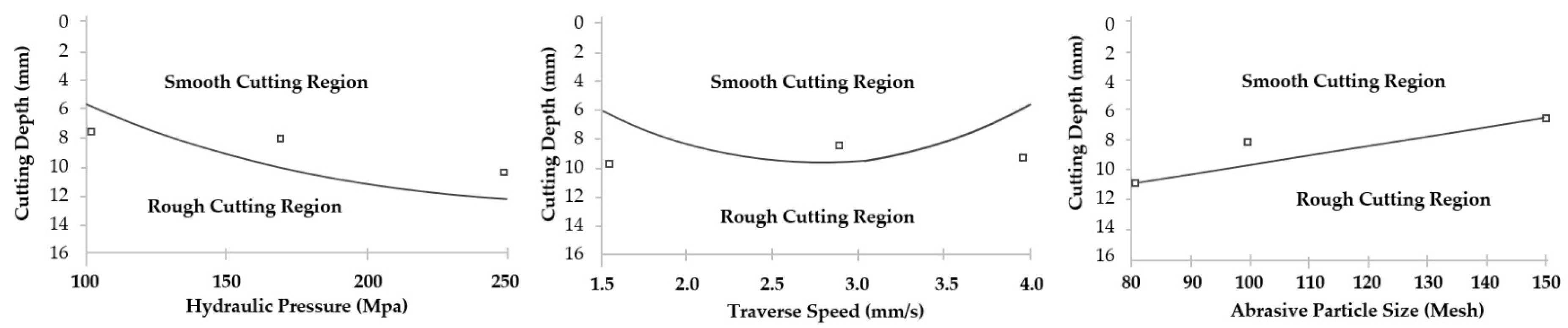
In general, the variation of this defect according to the established cutting parameters can be seen in
Figure 6 [
30,
31].
As shown, the taper decreases significantly with an increase in pump pressure, as this increases the cutting energy. On the other hand, the influence of the traverse speed follows the same trend as the previous case: the taper increases with the increase in the traverse speed. Finally, an increase in the abrasive diameter reduces the formation of the taper due to the increase in the cutting capacity given to the water jet, minimizing the loss of kinetic energy [
31]. A comparison of articles focusing on the taper defect as a function of the type of material is shown in
Table 1.
3.1. Cutting Geometry in Metal Alloys
Kumar et al. [
42] carried out a parametric study of AWJM on a carbon steel EN8, in which pressures varied between 3200 and 3600 bar, abrasive mass flows between 250 and 450 g/min, and a traverse speed between 154 and 220 mm/min. The average width of the cut made for each combination was evaluated, as well as the angle of taper originated. In this study, it was determined that the combination of a pressure of 3600 bar, the highest, with, likewise, the highest values of abrasive mass flow and traverse speed, generates the lowest taper angle. This combination is associated with a maximum kinetic energy of the water jet with a maximum cutting capacity, having a high number of abrasive particles impacting against the surface. In addition, by increasing the speed of the jet, the collisions between abrasive particles may be reduced, producing a more homogeneous cutting process.
Dhumbare et al. [
43] carried out a parametric study using a 6 mm thick mild steel as target material. They performed an ANOVA statistical analysis in order to determine the statistical influence of three input variables on the geometry of the taper angle cut. The input variables were the traverse speed (85–567 mm/min), the standoff distance (3–7 mm) and the abrasive mass flow (390–450 g/min). This study concludes that, for a constant hydraulic pressure, the most influential parameter in the generated conicity is the traverse speed, followed by the standoff distance. In addition, the authors established a series of predictive models through a response surface methodology using second-order quadratic models in which they related these input variables with the results obtained for the taper angle.
An increase in the standoff distance has a direct effect on the final quality of the cut. At large distances, the water jet dispersion is increased. This dispersion generates a region of greater area affected by the abrasive particles and increases the taper defect. At the same time, this dispersion reduces the kinetic energy of the water jet, reducing its cutting capacity.
On the other hand, Kumar et al. [
42] indicate that an increase in the traverse speed produces a great conicity. This produces a loss of kinetic energy in combination with the displacement of the jet itself. This loss in kinetic energy reduces the cutting capacity at the exit of the material, producing a very small bottom width compared to the top.
At the same time, the interaction between input variables also directly influences the taper obtained. A standoff distance with a reduced abrasive mass flow considerably increases the taper, even if the complete cut is not made in the thickness of the steel. This is due to the loss of kinetic energy and the fact that there comes a time when there are not enough abrasive particles to erode and machine the material. Similarly, it is advisable a combination of a small standoff distance with a reduced traverse speed.
The low separation distance allows abrasive particles to pierce the workpiece with a high density of kinetic energy. On the other hand, a low traverse speed increases the number of abrasive particles impacting the workpiece [
43].
As previously mentioned, the ability to perform the machining correctly and allow the water jet to pass completely through the material is related to its cutting ability. In this sense, Pon et al. [
52] carried out a parametric study in water-jet machining on a mild steel with a high thickness of 70 mm. The established variables were the hydraulic pressure (2700–4000 bar), the traverse speed (25–150 mm/min), the abrasive mass flow (480–900 g/min) and the standoff distance (1.8–5 mm). The authors determined that the capacity to completely penetrate the material is directly related to the hydraulic pressure (
Figure 7). This is due to the fact that high pressure increases the kinetic energy of the jet, maximizing its cutting capacity and, therefore, being able to penetrate large thicknesses.
This ability to penetrate also depends directly on the abrasive mass flow granted to the water jet. A greater quantity of abrasive particles increases the cutting capacity of the jet, generating a greater quantity of impacts that erode and eliminate small quantities of the material. Hence, for large thicknesses, it is advisable to combine high hydraulic pressure and abrasive mass flow.
The use of a high traverse speed and the establishment of a large standoff distance reduces the penetration capacity of the water jet. This combination produces a greater conicity and prevents the jet itself from completely crossing the thickness (
Figure 8). This is due to the deficit of abrasive particles impacting against the surface, in combination with a very high jet translation, which causes the cutting capacity of the jet in a local area to be insufficient, producing an incomplete and irregular cut [
53].
In addition to the previously commented cutting parameters, and inherent to the water-jet cutting process itself, there are other input parameters specific to the material under study or elements of the equipment used.
Kechagias et al. [
49] carried out a study on the cutting of mild steel by means of this technology. In addition to the input variables studied by another author such as the feed rate or the jet-piece distance, the authors modified two external variables such as the thickness of the material under study and the diameter of the nozzle used.
This study agrees with other authors’ research, concluding that the combination of a low traverse speed and standoff distance induces a smaller taper angle. In addition, it established that the most influential parameter in the conicity of the cut is the diameter of the nozzle to be used. The authors emphasized that a nozzle diameter as small as possible should be used in order to obtain the minimum conicity.
This is due, as well as the jet-piece distance, in that a larger opening implies greater hydraulic pressure to maintain the kinetic energy of the water jet. On the other hand, an increase in the thickness has a significant effect on the conicity. Reduced thickness minimizes resistance to machining and reduces loss of kinetic energy. This is in agreement with Pon’s research [
52], which indicates that it is necessary to apply greater hydraulic pressure to increase the kinetic energy and, thus, completely cross the thickness of the material under study.
3.2. Cutting Geometry in Polymeric Matrix Composites
Machining of composite materials, both thermoset and thermoplastic, remains a challenge today. The anisotropy of the material, the many configurations and the variety of thicknesses that can be obtained make AWJM machining a complex process.
From the point of view of cutting geometry, low thickness machining is shown as the most critical configuration, due to possible delamination formations. In addition, while in metal alloys erosion is more visible, this defect can become more complex to analyze in composite materials owing to the conicity generated (
Figure 9).
Dhanawade et al. [
44] conducted a study on abrasive water-jet cutting in a thermoset polymer matrix composite material. The CFRP used was 26 mm thickness. In this study, authors carried out a response surface methodology combined with an ANOVA statistical analysis to determine the influence of the cutting parameters. The authors indicate that the most influential parameter in the taper angle is the hydraulic pressure, because an increase in this parameter generates a greater kinetic energy in the jet, increasing its cutting capacity and reducing its conicity. On the one hand, the taper is directly influenced by the amount of impact of the abrasive particles and the kinetic energy given to the water jet.
Additionally, an increase in the nozzle traverse speed reduces the overlapping of abrasive particle impacts, reducing its cutting capacity and, therefore, increasing the taper angle [
54]. The kinetic energy is also reduced with an increase in the distance of the jet from the workpiece because it generates a greater dispersion of the jet at the exit.
Finally, Dhanawade determined the influence of abrasive mass flow on taper. A small increase in it decreases the conicity obtained due to the greater cutting capacity of the jet. However, an excessive increase in the quantity of abrasive particles produces a collision between them, rounding their edges and reducing their cutting capacity, which generates a greater angle of conicity. This is consistent with the results obtained by Pahuja et al. [
45]. They machined samples with 10 mm in thickness and obtained a very small cutting width and high taper employing low hydraulic pressure, a high traverse speed and a small number of abrasive particles. This combination of parameters has the same influence on the study by El-Hofy et al. [
24], where 10.4 mm is the thickness of the thermosetting composite material. El-Hofy et al. indicate that the minimum taper can be obtained by applying high hydraulic pressure in combination with a small distance between the nozzle and the surface of the material. However, the taper obtained is reduced by increasing the feed rate, contrary to Dhanawade. This is because, with high pressure, an increase in the feed rate generates a smaller top width, producing a more constant cut.
As mentioned above, the distance between the nozzle and the surface is a very important parameter for the taper to be obtained. This is mainly due to the loss of energy in the form of jet dispersion when coming out of the nozzle. Most studies indicate that the recommended distance is located in the range of 2 and 3 mm [
34,
46,
55].
Popan et al. [
47] studied the influence of the variation of the jet-piece distance for a thickness of 6 mm. The authors highlighted that with a considerable reduction of up to 0.5 mm of distance, the upper cutting width (
Wt) is considerably reduced, decreasing the conicity (
Figure 10). This is in line with the results presented by Youssef et al. [
56]. It is worthy of note—how a reduction in the standoff distance produces a decrease in the radius of the area affected by erosion (IDR) due to the initial impacts of the abrasive particles.
Finally, a reduction in material thickness enhances the influence of parameters considered less influential in large thicknesses. In this line, Wong et al. [
48] studied water-jet cutting in a thermoset composite material with a thickness of 3 mm, concluding that the most relevant parameter in the conicity are the combination between the standoff distance and the traverse speed.
From this section, the direct influence that presents the hydraulic pressure and the distance jet-piece in the conicity generated in the composite material is concluded. These parameters act directly on the kinetic energy given to the water jet, as well as the dispersion of the jet itself when coming out of the nozzle. Therefore, minimum values of taper have been generated when a reduced jet-piece distance, close to 1 mm, is combined with high values of hydraulic pressure, close to 300 MPa. Finally, a reduction in the thickness of the composite material enhances the direct influence of the rest of the cutting parameters.
3.3. Cutting Geometry in Hybrid Structures
In the previous sections, the main results corresponding to the cutting geometry generated in abrasive water-jet cutting, both in polymeric matrix composites and in different steel alloys, have been presented. However, as explained in previous sections, these materials are being combined in the form of hybrid structures in order to combine the properties they offer separately, so they are joined together and then machined at the same time to give them the geometry required to fulfil their function [
34]. Due to the complexity caused by very different properties and nature, its machining as a whole is considered a critical process, of great interest at present.
In addition, when a hybrid structure is obtained, a new input variable arises that belongs to the configuration of the materials and that can greatly affect the final result of the machining. This is the order in which the materials are stacked when composing the stack, since the same results will not be obtained in configurations where the metal is located at the top of the stack, or if a composite is located in this position.
It is also noteworthy in terms of published literature that most of it focuses on studies of thermoset composite and light alloy stacks of titanium or aluminum [
32,
34], for their high interest in the aeronautical sector.
Ruíz-García [
34] developed a parametric study to evaluate the influence of cutting parameters and stacking order in abrasive water-jet drilling in a hybrid CFRP/UNS A92024 (Al-Cu) structure. The analyzed variables were the hydraulic pressure (1200–2500 bar), the traverse speed (15–45 mm/min) and the abrasive mass flow (170–340 g/min). When the order of stacking is CFRP/UNS A92024, it was observed that shear forces of the abrasive particles pull out parts of the composite materials which may remain adhered in the final region of the metal alloy. This process is caused by the formation of grooves or lag due to the loss of kinetic energy in the water jet output. The formation of an unusual cutting geometry in comparison with those obtained when both materials are machined separately is particularly noteworthy, and it can be seen how the conicity obtained in the first material presents a totally opposite opening in the second material (
Figure 11).
This defect, also studied by Pahuja et al. [
32], is associated with a convergence and subsequent divergence of the water jet due to the turbulence that occurs in the interspace between the two materials. This defect, called “hydrodistortion” by some authors [
17], occurs when the water jet loses cutting energy, resulting in a rough area. In turn, due to the different machinability of the materials, the metal alloy absorbs more cutting energy, causing the jet to transversely mechanize the composite material and weakening the joints between both materials (
Figure 12).
In Ruiz-García’s research [
34], it is also indicated that the most appropriate order of stacking should be first the composite material followed by the metal alloy, an orientation that achieves that most combinations of cutting parameters offer little variation in the conicity obtained in both materials due to the fact that the water jet suffers a lower loss of kinetic energy when passing through them. This is also in accordance with what Pahuja [
14] has explained, as shown in
Figure 13, which graphically represents the energy dispersion suffered by the water jet as it passes through the materials that make up the hybrid structure.
In this way, a great dissipation of kinetic energy is produced in the machining of the metal alloy due to its mechanical properties, as it offers a greater resistance than the composite material to be machined. This means that, in the last section corresponding to the composite material, the jet has a minimum cutting capacity, being able to produce a separation between the layers that compose it, in the form of delamination. Therefore, the most influential parameter in the cutting geometry of a hybrid structure CFRP/UNS A92024 bonded mechanically is the abrasive mass flow, followed by the transverse speed.
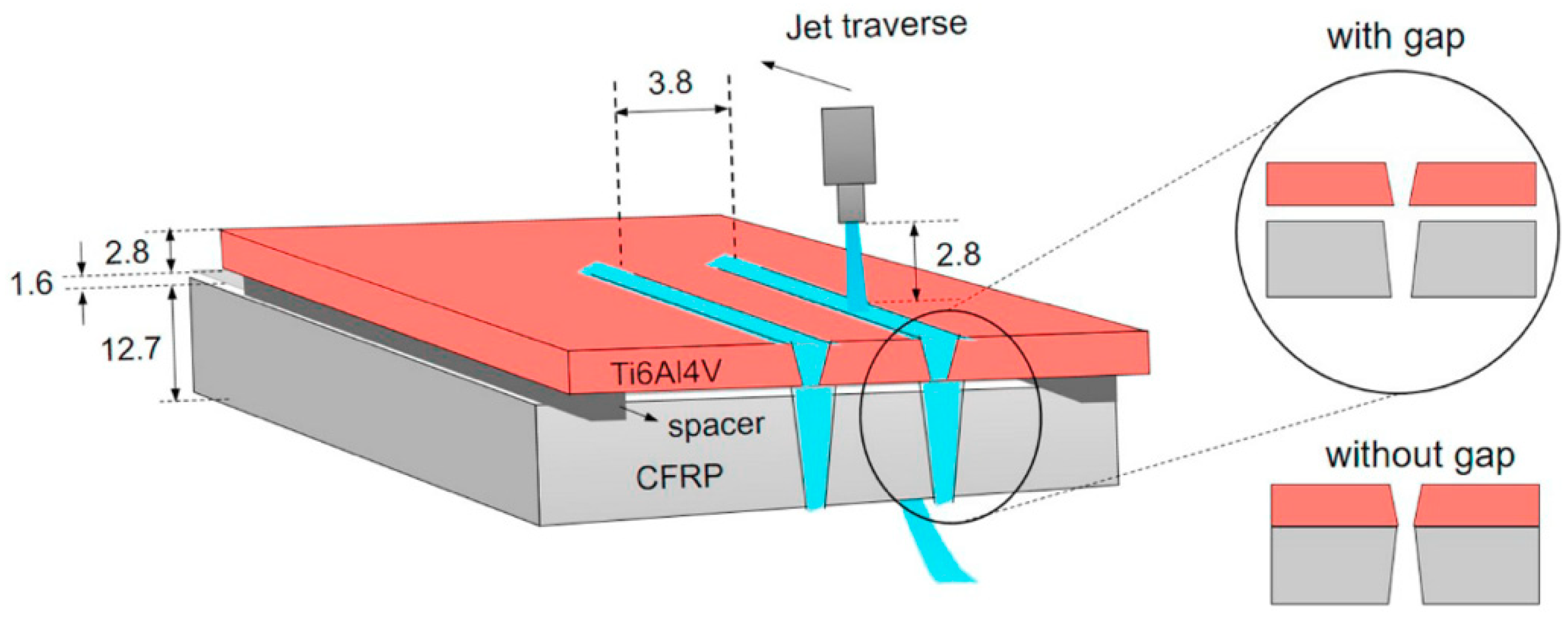
In order to eliminate this double cone angle due to the hydrodistortion generated, Pahuja et al. [
14] studied the machining of a hybrid CFRP/Ti6Al4V structure in a special configuration—both materials being separated by small gauges that allowed the water jet to exit freely from the first material and prevent damage to the interlayer of both materials (
Figure 14).
A defect was also identified in the metal alloy normally associated with other conventional processes, such as drilling or milling, which consists of the formation of small irregularities or burrs in the water-jet exit zone. Titanium is machined by means of small impacts of abrasive particles that make a superposition of shear forces. Due to the dissipation of commented kinetic energy, a plastic deformation is generated in the final moments of the titanium alloy, in the form of a burr. On the other hand, Li et al. [
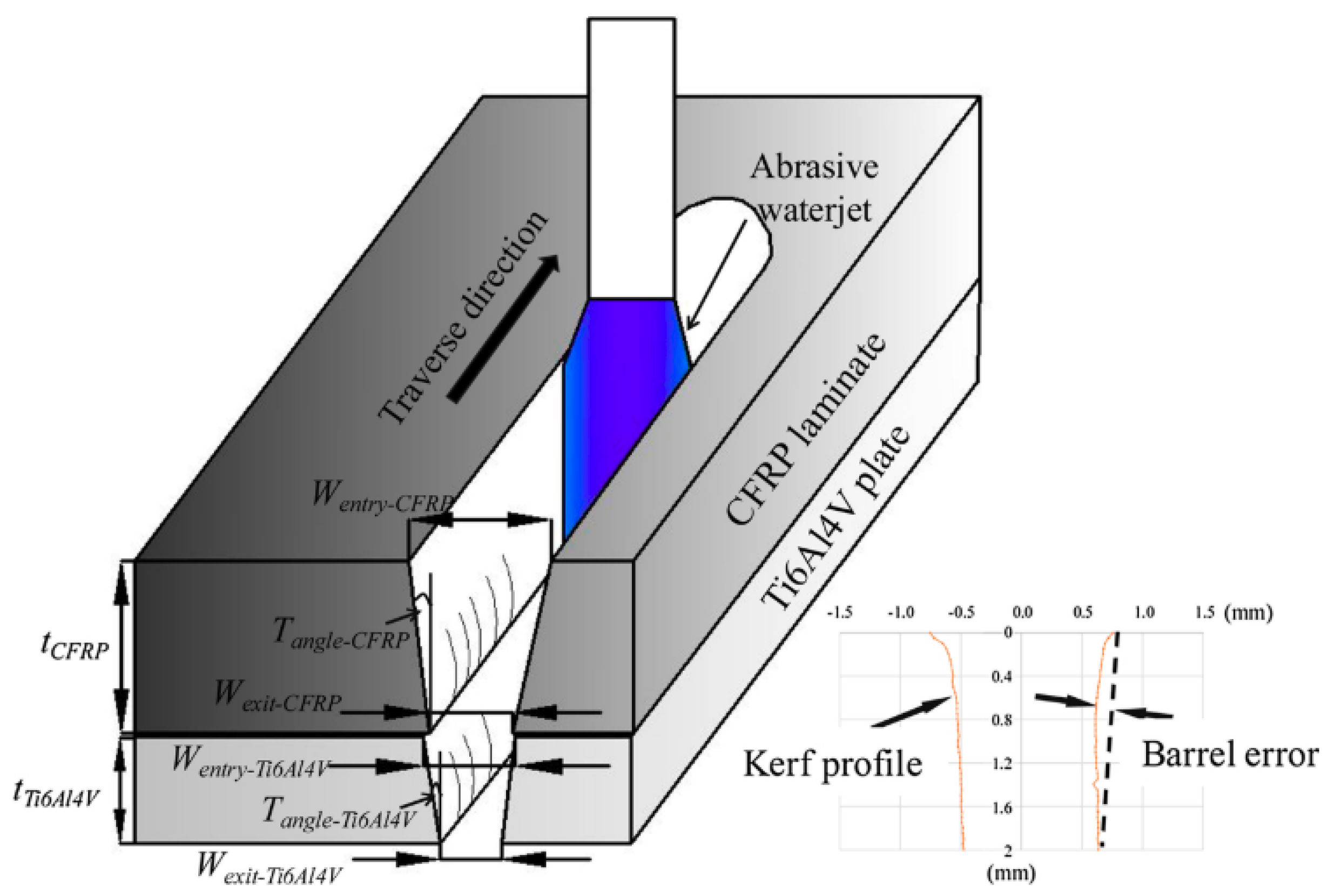
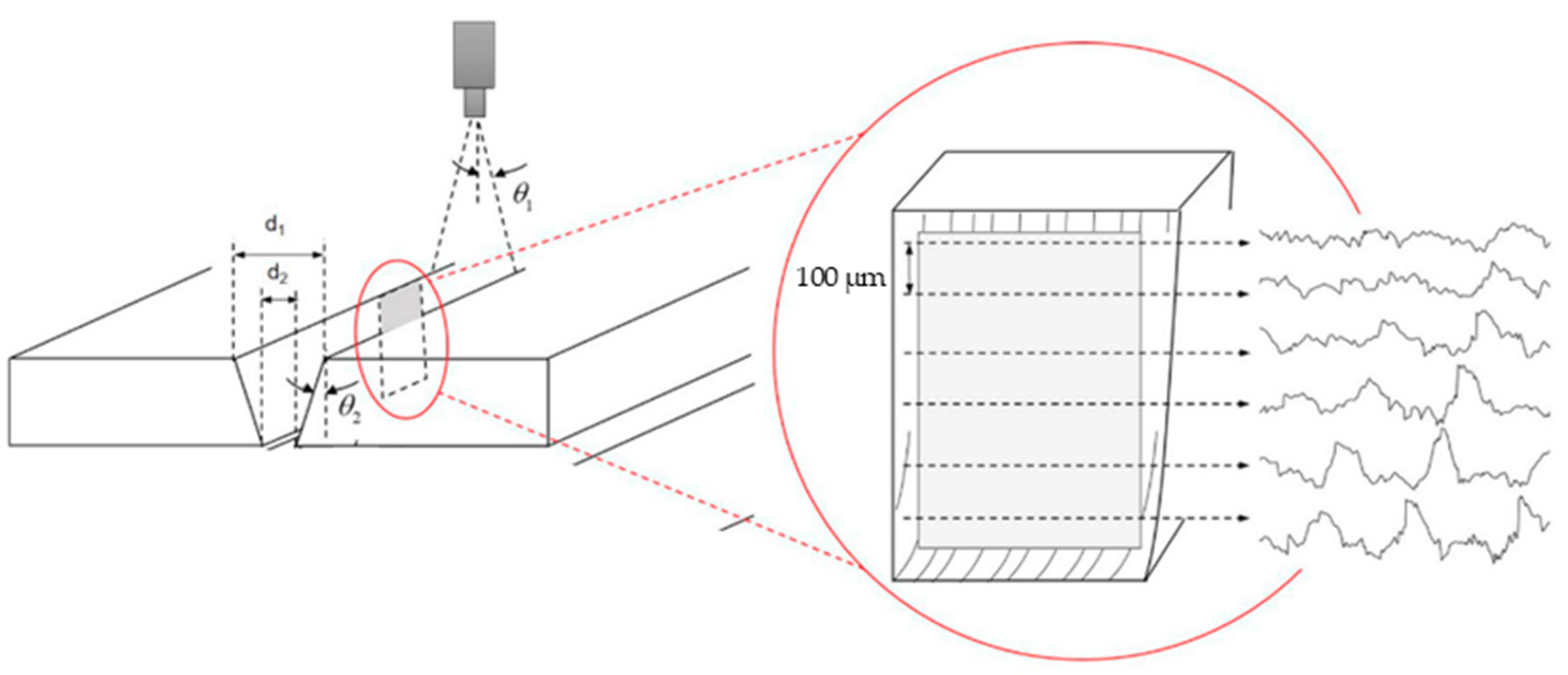
51] established results close to those previously commented. In their study, the authors mechanized, by abrasive water jet, a hybrid CFRP/Ti6Al4V structure in its two possible stacking configurations. In this study, as mentioned at the beginning of the section on water-jet cutting, it was identified that the erosion zone at the entrance of the material can distort the taper angle measured with traditional methodologies, establishing an error bar in their results in order to identify how far this linear regression is away from the actual curvature generated by the water-jet entrance (
Figure 15).
As well as Ruiz-Garcia and Pahuja, Li identified that, in the machining of its hybrid structure, the effect of hydrodistortion was also generated, generating a double cone angle in both materials, but pointing out that this defect only arises when the first material of the hybrid structure consists of the metallic alloy, while in the opposite order, the cone presents the same tendency in both materials.
As can be seen from the above, this defect is strongly related to the hydraulic pressure applied prior to cutting. A higher hydraulic pressure generates more energy to the water jet capable of machining both materials at the same time. However, there is a coincidence of results when the composite material is the first material in which the water jet impacts, in which the loss of kinetic energy is lower, generating a reduced conicity in both materials.
4. Associated Defectology in AWJM: Surface Quality
Abrasive water-jet cutting produces a very specific surface quality due to the abrasive nature of the process. The kinetic energy given to the water jet and its dissipation during the cut itself is a fundamental aspect for the geometry of the cut, and the same applies to the surface quality obtained.
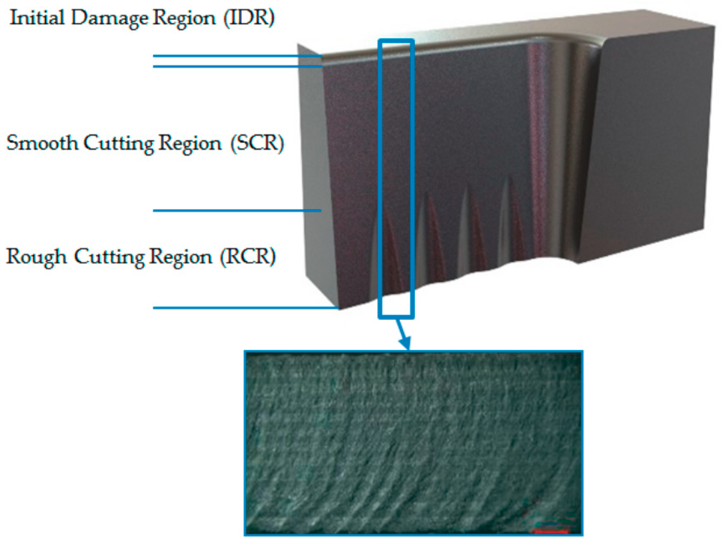
In the initial moments, as the water jet presents its maximum cutting capacity, the abrasive particles begin the superposition of impacts against the surface of the material to start the cut. This generates a small area more affected by erosion, which is called IDR (initial damage region) [
34].
Initial damage region or IDR is present in all cuts made by AWJM, being the separation distance between the nozzle and part of the predominant parameter in terms of influence on the appearance of this defect [
2] (
Figure 16). Furthermore, an increase in the standoff distance generates a more conical geometry, producing a deeper erosion-affected region.
After this small located region, there is the area corresponding to the best surface quality generated by the water jet, called the SCR (smooth cutting region), which corresponds to the surface that presents less irregularities, with a formation of smooth peaks and valleys. The correct selection of cutting parameters greatly affects the formation of this zone and the final quality of the roughness obtained (
Figure 17).
An increase in hydraulic pressure and grain size of the abrasive used, along with a reduced traverse speed, can provide a maximum area that can be considered smooth and without apparent damage. This combination gives the maximum cutting capacity to the water jet, being essentially the correct selection of the advance speed, because a very high speed generates a great dispersion of the kinetic energy in the initial moments, producing a greater variation in the obtained surface quality.
The last region that can result during the cutting process is the denominated RCR (rough cutting region), which is associated with the final loss or dissipation of kinetic energy of the jet itself. This causes the succession of impacts of the jet particles to be carried out in an irregular manner and, sometimes, without correctly detaching and shearing the material in its final moments. The three regions mentioned are represented in
Figure 18.
The combination of these three regions results in the presence of different peaks and valleys, with large and irregular distances, generating an area with a higher roughness and poorer surface quality. This region coincides with the appearance of a wave pattern known as “lag” or jet delay (
Figure 19).
As with the taper generated, the surface quality in water-jet machining is directly related to the kinetic energy of the water-jet and varies throughout the material thickness. Thus, three different quality zones arise depending on the stability of the water jet, the first being eroded by abrasive particles, the second being smooth due to the stabilization of the water jet and the third being very rough due to turbulence at the outlet. In turn, if the output of the water jet is very unstable can generate a defect known as lag due to the delay between the initial and final cut in the displacement of the water jet. A comparison of articles focusing on the taper defect as a function of the type of material is shown in
Table 2.
4.1. Surface Quality in the AWJM of Metal Alloys
Abrasive water-jet machining of metal alloys requires higher hydraulic pressure levels than those established for machining of composite materials. Thus, set hydraulic pressures that generate good surface quality in composite materials can produce a very rough surface in metal alloys. Due to this, different investigations about abrasive water-jet cutting in different metal alloys can be found, which address how the cutting parameters affect the surface quality obtained and determine which combination provides the best quality [
28,
65].
Gaidhani et al. [
66] investigated the machining of stainless steel plates, performing a parametric test to determine the percentage of influence of various input parameters on the quality obtained, and concluded that the main parameter is the jet-piece distance with a 19% influence, followed by the traverse speed with 17%. However, the article recognizes that the hydraulic pressure is not analyzed and highlights that it should be studied later.
Chithirai et al. [
61] focus on the analysis of the effect of process parameters on surface quality and depth of cut, in order to establish the cutting performance by AWJM in 304 stainless steel with a thickness of 60 mm. It indicates that the water-jet pressure has the greatest effect on the surface quality. An increase in hydraulic pressure produces an increase in the penetration capacity of the jet itself into the material. In turn, it produces a decrease in the average roughness (Ra) values obtained.
The authors recommend high hydraulic pressures, low traverse speed and low jet-piece distance. On one hand, an increase in hydraulic pressure generates a higher kinetic energy to the abrasive water jet, maximizing its penetration capacity and reducing the resistance of the material to be machined. Consequently, the lag defect in the RCR decreases and the surface quality improves. On the other hand, low traverse speed and jet-piece distance provide a smooth surface in the initial moments.
As with the results obtained for machining composite materials, an increase in the nozzle traverse speed produces an increase in the roughness generated due to the dissipation of kinetic energy from the jet, resulting in the third highest roughness region (RCR).
Murugabaaji et al. [
62] carried out an experimental investigation on abrasive water-jet machining on a 40 mm thick stainless steel through a response surface methodology, studying the influence of hydraulic pressure, traverse speed and abrasive grain size on surface quality through ANOVA statistical analysis. This analysis showed that a combination of the highest level of hydraulic pressure (3000 bar) with a small abrasive size and the lowest level of traverse speed (30 mm/min) produces the best surface quality by obtaining minimum Ra values close to 2 µm.
A more complete study was carried out by Badgujar et al. [
67], in which several levels were modified for a wide range of input parameters such as hydraulic pressure, type of abrasive, blast distance, abrasive mass flow and traverse speed. The aim of this research is to study their influence on the surface quality obtained in a SS304 stainless steel. In general, the surface quality improved by increasing the levels of the established cutting parameters, with the exception of the size of the abrasive particles. The authors stated that it occurs in the same way with the increase in the hydraulic pressure, in opposition to the results exposed by previous authors. This is associated with the fact that an increase in the pressure increases the kinetic energy of the abrasive particles, improving their cutting capacity. However, this can lead to random collisions between the same particles generating a rougher surface. This increase in energy can result in a fragmentation of the particles inside the nozzle thus reducing its size and cutting capacity.
Dumbhare et al. [
43] performed a study similar to the investigations described above, changing the type of steel as study material. In this case, he focused on the abrasive water-jet machining of a 6 mm thick mild steel, evaluating the surface quality in terms of Ra, obtaining values between 2 µm and 6 µm.
In terms of surface quality, the traverse speed is the parameter that has the greatest weight in the results obtained, followed by the standoff distance. On the contrary, an increase in the mass flow hardly varies the results obtained, which may be due to the thickness of the material, much lower than those used in the previously mentioned investigations. This study develops a predictive mathematical model of second order that relates the surface quality with the traverse speed and the jet-piece distance, with an adjustment of 99.93%, marking as ideal parameters in terms of Ra a traverse speed close to 85 mm/min with a jet-piece distance of 3 mm, which are also in accordance with those previously obtained by Pon et al. for the water-jet machining of a carbon steel.
The previous results also agree with those obtained by Rao et al. [
53] in the machining of a carbon steel. This study concludes that the surface quality is directly related to the traverse speed used. However, similar to the study by Badgujar et al. [
67], an increase in hydraulic pressure can be counterproductive. Although an initial increase in hydraulic pressure decreases the Ra values obtained, as the hydraulic pressure continues to increase, Rao detects a worsening of the surface quality.
Additionally, Kechagias et al. [
49] present an interesting comparison of the influence of various cutting parameters when modifying the diameter of the nozzle used. On the one hand, the surface quality is significantly affected by the diameter when the thickness is very small, with less variation when the thickness increases. On the other hand, an increase in the diameter of the nozzle in combination with an increase in the jet-piece distance generates the worst surface quality by producing a great dispersion of the jet itself upon leaving the nozzle, generating a large eroded zone and an early appearance of the rough zone (RCR). Finally, it is indicated that the traverse speed is one of the most influential parameters in the surface quality, in total agreement with the rest of authors. However, for a low rate of advance, an increase in the diameter of the nozzle can worsen the surface quality. On the other hand, an increase in the traverse speed does not show a direct relationship with the diameter, with lower Ra values than for a low traverse speed, which can match them in large diameters.
Thus, due to the homogeneity of the metallic alloys, the formation of the three regions of different surface quality is more visible, but with a smoother transition between them. Due to its mechanical properties, generally superior to those presented by composite materials and its high machinability, its machining by abrasive water jet requires more energy for the jet to pass completely through the material [
52].
4.2. Surface Quality in the AWJM of Polymeric Matrix Composites
The anisotropy and great amount of existing combinations of stacking within the composite materials, as well as the possibility of combining different reinforcements or matrices, make the surface quality obtained in these materials a very important aspect that must be controlled.
In terms of cutting thickness, Jagadeesh et al. [
57] showed that increasing thickness in CFRP machining has strong wear effects on the surface quality, while increasing the traverse speed significantly deteriorates the surface quality.
Ming et al. [
55] have studied the influence of cutting parameters on surface quality through the response surface methodology, obtaining a mathematical model that allows predicting optimal ranges for the cutting parameters. The study material consisted of a hybrid composite of carbon fiber and glass fiber reinforcements and epoxy type matrix with a final thickness of 3.5 mm. When machining such a low thickness, they include the idea that there are only two regions corresponding to the initial erosion and the soft zone, instead of the three previously exposed. This is due to the fact that by presenting such a low thickness and the mechanical properties of the composite material, the water jet does not suffer a considerable dissipation of kinetic energy that could generate a zone of great roughness at the exit of the material.
At the same time, an ANOVA statistical analysis indicates that the abrasive flow mass is the main factor affecting surface quality, followed by the separation distance and hydraulic pressure. Similar results have been obtained by Kumaran et al. [
58] who conclude that high hydraulic pressures with low rates of transverse speed improve surface quality, using an ANFIS model in the range of 220 and 260 bar for hydraulic pressures, 20 and 40 mm/min for transverse speed and 1–3 mm for separation distance.
In this same line, authors such as Ahmed et al. [
59] and Bhowmik et al. [
60] obtain similar results, showing the same influence of the cutting parameters through predictive models based on a response surface methodology (RSM).
El-Hofy et al. [
24] studied the influence of cutting parameters in two different configurations of CFRP composed of an autoclave-cured epoxy resin with T800 module fibers and a final thickness of 10.4 mm. The cutting parameters were the hydraulic pressure (1000–3500 bar), traverse speed (50–150 mm/min) and standoff distance (2–4 mm). This study concludes that hydraulic pressure is the most important variable affecting in surface quality, which does not agree with the results obtained by Ming et al. [
55], which indicate that the most relevant parameter is abrasive mass flow.
This difference in results may be due to the thickness of the machined material. In reduced thicknesses, close to 2 mm/min, a good surface quality can be achieved depending on the flow of abrasive particles. On the contrary, when the thickness of the material increases, close to 10 mm, the machining capacity generated by the hydraulic pressure seems to be more decisive. El-Hofy indicated that, as the hydraulic pressure increases, the kinetic energy of the water jet increases, reducing the delay generated by the high cross-feed and thus improving the quality of the final surface.
From the literature reviewed, it is clear that there is no consensus on the relationship of influence of the parameters that govern the process and surface quality in composite materials. The anisotropy of these in combination with the thickness that they present makes that more studies should be carried out focused on optimizing this parameter to fill up this gap of knowledge. In turn, the literature focuses on the machining of thermoset composites and studies focusing on thermoplastic composites are needed.
4.3. Surface Quality in the AWJM of Hybrid Structures
The different machinability of materials, in particular between polymer composites and metal alloys, means that combinations of cutting parameters do not produce the same result when machining them as a hybrid structure. As with the taper generated, the order of stacking, thickness or type of bond between the two materials can be a factor that greatly affects the surface quality obtained.
The main metallic alloys used in the form of a hybrid structure are light alloys, aluminum [
1,
68] or titanium, especially the alloy Ti6Al4V [
13,
69], in combination with a polymeric composite material.
Ruíz-García et al. [
34] highlights the importance of the stacking order in water-jet machining, studying a hybrid CFRP/UNS A92024 (Al-Cu) structure in both configurations. The authors indicate that an increase in the roughness generated in both materials has been observed by increasing the traverse speed and reducing the number of abrasive particles. This especially affects the metallic alloy, in which a greater variation in the surface quality is appreciated by reducing the abrasive mass flow. This effect occurs when the alloy is at the exit of the jet, since, by reducing the number of abrasive particles, the cutting capacity of the jet after machining the composite material is very reduced, generating a very rough surface and may form the defect of jet delay or lag.
Additionally, the order of stacking also influences the formation of the eroded zone at the entrance of the water jet (IDR). While the first material, where the jet starts cutting, always generates this region of greater initial roughness, the second material can form a much softer region or even one non-existent (
Figure 20). The reason may be that that when both materials are joined, the first material can serve as a protective layer, thus reducing the erosive effect of particles in the initial moments [
34].
If the first material is the metal alloy, it absorbs most of the kinetic energy of the water jet, reducing its cutting capacity. Due to the anisotropy of the elements that compose the composite material (matrix and reinforcement) the water jet produces a higher roughness. On the one hand, the impacts of the jet particles eliminate the polymer matrix. This leaves the reinforcement unprotected. On the other hand, the loss of energy in the water jet bends the reinforcement without removing it completely. This produces a surface with loose carbon filaments and cavities where the matrix should be, resulting in a worse surface quality [
51].
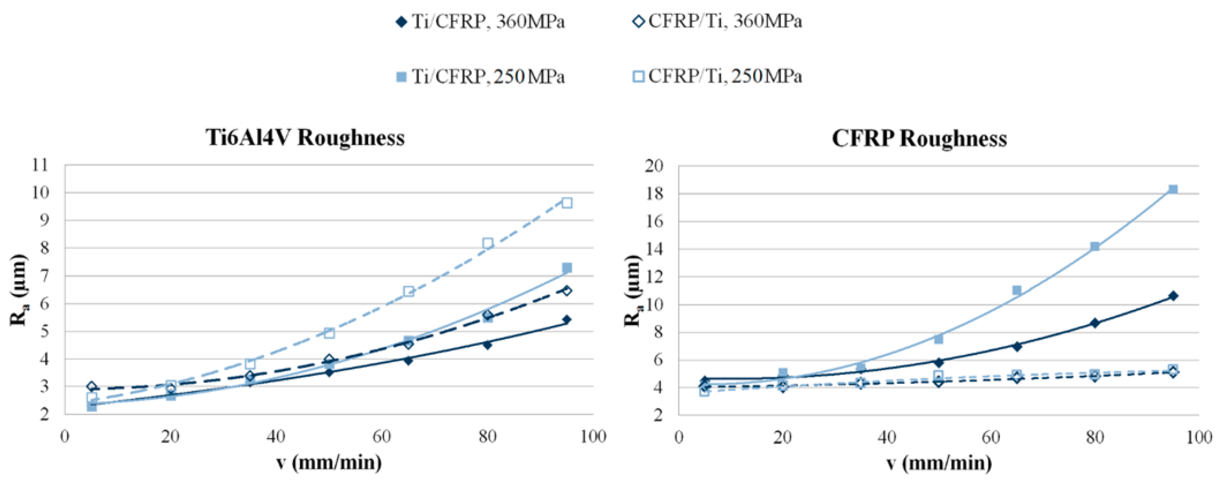
Li et al. [
51] indicate that, due to the different nature of the materials, the Ra values obtained are very different between both materials. Thus, the highest values of Ra are always reached in the composite material due to its anisotropy. Depending on the orientation of the carbon fibers, they are more likely to be completely eliminated when the jet is perpendicular. This fact, together with a more effective removal of the matrix results in a greater variation of the surface.
This difference in results is substantially amplified when presenting a metal/CFRP configuration, in comparison with CFRP/metal, where the Ra values are quite close when increasing the hydraulic pressure and reducing the advance speed, being thus in accordance with what has been exposed by other authors (
Figure 21).
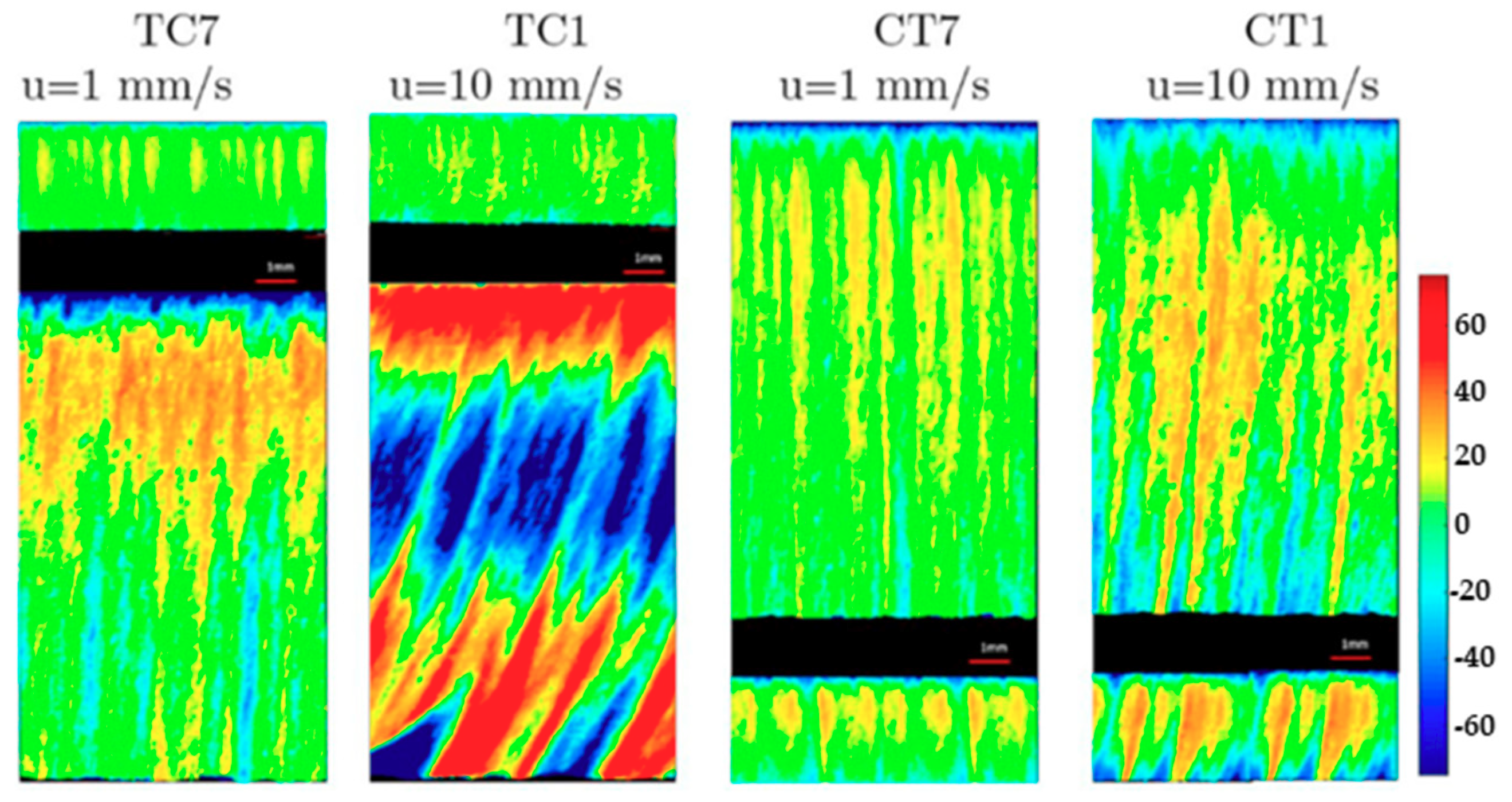
Pahuja et al. [
14] also explain the importance of traverse speed in water-jet machining of a hybrid CFRP/Ti structure. Here, by increasing the speed from 1 mm/min to 10 mm/min, the Ra values increase by 14% for the titanium alloy and 260% for the composite material (
Figure 22), which highlights the importance of this parameter.
As explained by Ruiz-Garcia et al. [
34] and Li et al. [
51], when the first material of the hybrid structure is the metallic alloy, the surface quality obtained is very different between both materials.
In this study, the roughness was increased by up to 72% with a reduction in the size of the nozzle orifice and an increase in the thickness of the sample, which is associated with a small orifice diameter injecting less mass flow of water, generating a rougher surface. In addition, a greater thickness give rise to a greater depth of penetration and a greater loss of energy, which causes more erosive wear instead of a sharp cut on the outlet side of the jet, generating a spiked and rougher surface.
In fact, the composite material was not properly machined for some combinations because the jet did not have enough cutting capacity when trying to machine the last region of this material, generating non-machined areas at the exit.
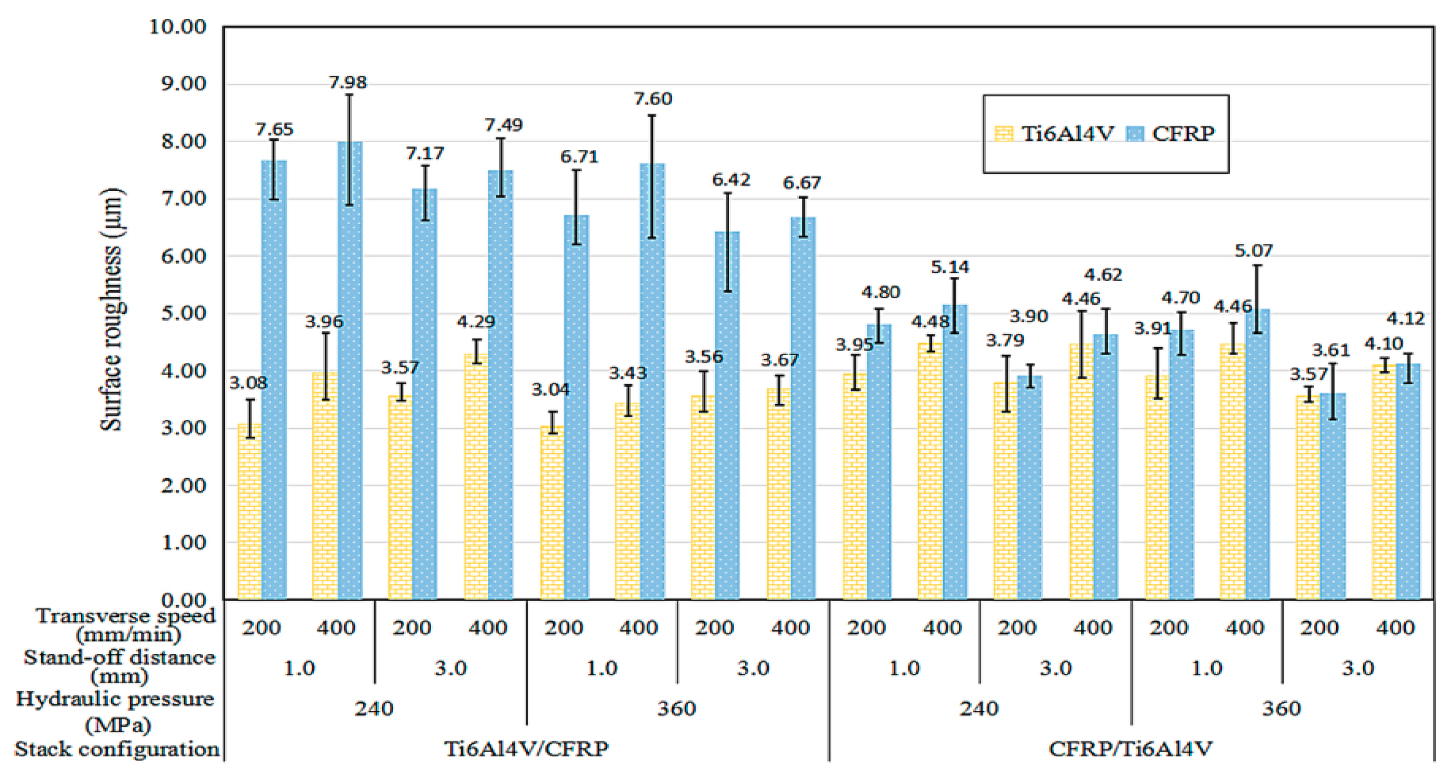
This influence was also studied by Alberdi et al. [
50] in the water-jet cutting of a hybrid CFRP/Ti6Al4V structure in both configurations. An ANOVA analysis corroborated the above, where the most influential factor in the surface quality of both materials is the traverse speed. However, the author highlighted that in the machining of a hybrid structure, the order of stacking before other parameters such as hydraulic pressure or abrasive mass flow has a greater influence on the surface quality obtained (
Figure 23).
On the other hand, Pahuja et al. [
17] studied water-jet cutting in an FML made up of titanium and graphite plates joined by a Polyether ether ketone (PEEK) thermoplastic matrix with a final thickness of 10.75 mm and 7.56 mm, indicating that for large thicknesses the jet loses cutting energy, resulting in a rough area. At the same time, it detects the appearance of the hydrodistortion phenomenon. Due to the different machinability of the materials, the metallic alloy absorbs more cutting energy, causing the jet to transversely mechanize the composite material and weakening the joints between the two materials.
By machining such large thicknesses, Pahuja confirmed the existence of the three regions previously indicated in the water jet cut for an FML constituted with a thermoplastic matrix, evaluating the surface quality in terms of Ra. This is in line with the results of Fengchao et al. [
70], which show the evolution of the surface quality after the machining of a Ti6Al4V alloy.
Thus, the machining of a hybrid structure should be selected at the most appropriate traverse speed, usually close to values below 100 mm/min, in order to avoid a dispersion of results in the machined thickness for both materials. At the same time, in order to improve the performance of the process and obtain the best surface quality in both materials, the composite material should be the first material to be machined by the water jet, with the metal alloy being the support material. In this way, thanks to the different machinability of both materials, the dispersion of kinetic energy is lower when coming into contact with the composite material, thus ensuring that the water jet is capable of correctly machining the metal alloy. In addition to this, parameters such as the jet-piece distance, are important in order to minimize the dispersion of the water jet as it leaves the nozzle and to reduce the loss of kinetic energy in both stacking configurations.

 ,
, 


