Angular Rolling of the Hollow Flanges of Pipe Joints


1
Department of Descriptive Geometry and Graphics, Faculty of Basic and Human Sciences, Saint-Petersburg Mining University, 2, 21st Line, 199106 Saint-Petersburg, Russia
2
Department of Micro- and Nanoelectronics, Faculty of Electronics, Saint-Petersburg Electrotechnical University «LETI», 5, pr. Popova, 197376 Saint-Petersburg, Russia
*
Author to whom correspondence should be addressed.
Metals 2021, 11(1), 166; https://0-doi-org.brum.beds.ac.uk/10.3390/met11010166
Submission received: 10 December 2020
/
Revised: 11 January 2021
/
Accepted: 12 January 2021
/
Published: 18 January 2021
(This article belongs to the Section Metal Casting, Forming and Heat Treatment)
Abstract
:The paper considers a three-stage technology for angular rolling of the pipe workpiece. This technology facilitates the expansion of the range of flange parts available by eliminating a number of drawbacks of the known methods of metal forming. In the presented paper, we analyze the results of numerical calculations and experiments, as well as the effective deformation values in blank material, using computer simulation in the DEFORM-3D software package. The results of the computer simulation were reached taking into account experimental studies of the rheological properties of copper alloy L68 in the form of a strain hardening curve using the Instron-8850 complex. The results of the ratio of basic geometric dimensions expanded the range of flange parts under investigation and allowed us to consider angular rolling technology with a variable angle of inclination of the rolling roll from a three-stage perspective, especially in small-scale production.
1. Introduction
In various industries, hollow axisymmetric parts with a developed flange are widely used, for example, in machine-building, metallurgical, gas, oil, refrigeration, electrical engineering, construction, etc. The range of these parts is very diverse and is regulated by various standards in our country and abroad. Parts with flanges provide reliable connections in hydraulic drives for various purposes, docking of parts in engineering products, LockRing connections in pipelines, and are the main element of structural passages that protect hydraulic and electrical communications from destruction. There are various manufacturing techniques for flange parts, including injection molding, hot forging, machining, but most of them are not distinguished by high metal utilization [1,2,3,4].
Casting is considered to be one of the simplest ways to obtain parts, the distinguishing feature of which is the presence of a sandy or metallic form to which molten metal is fed. The use of overpressure facilitates the filling of mold or liquid with liquid metal. However, the parts obtained are characterized by uneven mechanical properties and require time-consuming finishing operations, such as knocking, chipping, cleaning and the cleaning of castings.
Traditional hot die forging is economically unprofitable due to low serial production, as well as large allowances that increase the complexity of subsequent machining.
Another way to obtain axisymmetric thin-walled parts is mechanical processing. This method allows you to produce parts of various forms, but it is characterized by high labor intensity and the significant waste of metal into chips, which only makes the application of the method appropriate in single and pilot production [5,6].
Therefore, the most effective ways of obtaining such parts are the methods of volumetric shaping, such as traditional upsetting, rotary forging, orbital forging, radial extrusion, and axial rotary forging, allowing parts to be obtained with sufficient accuracy, practically without the loss of any material [7,8,9].
Axisymmetric parts with flanges located at some distance from the rotary forging (Figure 1) deserve special attention when choosing technology for their manufacture, due to the wide range of changes in the ratios of the main dimensions, which do not allow these products to be produced using one universal technology. Flange geometry is characterized by the basic flange: l is the length of the sleeve part to the flange, b is the flange width, and s is the wall thickness of a pipe workpiece (Figure 2).
In contrast to traditional upsetting [10], angular rolling technology has replacement deforming rolls, which have local contact with the workpiece. It can produce forces used for deformation in angular rolling that are much lower than in traditional upsetting. This means angular rolling technology exhibits the significant advantage of producing axisymmetric parts with a developed flange and good properties.
The use of rotary forging and cold orbital forging technologies with the force on the tool directed along the axis of the workpiece makes it possible to only obtain developed flanges from the rotary forging of the workpiece, effectively directing the flow of metal in radial forming [11,12]. Additionally, the direction of the deforming force in angular rolling technology coincides with the angle of dip of the roll to the axis of the workpiece. Moreover, the wider range of possibility when changing the angle of dip of the rolls at each stage of rolling allows for more effective control of the flow of the metal of the workpiece in both the radial and axial directions. This means that angular rolling technology exhibits a significant advantage in the production of axisymmetric parts with a developed flange located away from rotary forging.
Radial extrusion technology makes it possible to obtain a flange at almost any part of the pipe workpiece. However, the set of the required volume of metal to form a flange with a size ratio b/s ≤ 4.1 will require at least 4–6 transitions and is accompanied by defects [13], such as cracking, foldings, and loss of workpiece stability.
Choice of the rolling pattern is determined by the ratio of the height of flange h, the width of flange b, and the length of the sleeve part l to the wall thickness of the pipe workpieces.
For the production of parts with a developed flange in the rotary forging part with a ratio of sizes b/s ≤ 8.1, h/s ≤ 1.7, and l/s ≤ 1.2, face rolling schemes are used, for example, 1 and 2 in Figure 3. For the manufacture of parts with a flange significantly remote from the rotary forging of the workpiece, technologies 3 and 4 in Figure 3 should be used. It should be noted that this work has only determined the technological capabilities of five processes of cold volume forging for parts with flanges (Figure 3). This is because the other processes known do not extend to the nomenclature of the selected type of flanges.
There have been no reports so far on the application of cold forming metals technologies for the production of flange parts with a range of basic geometric dimensions b/s ≤ 5.4 and l/s ≤ 3.8. Production of this type of flanged part on the basis of a pipe workpiece requires a combined solution of volumetric metal distribution both in the radial direction, to form a developed flange of the required geometry, and in the axial direction, to form the sleeve portion.
The aim of this work is to develop three-stage angular rolling technology for a pipe workpiece, expanding the range of flanged parts obtained by controlling the flow of metal at each stage of forming by changing the angle of the rolling rolls. The parts under study involve the volumetric distribution of metal in both the radial and axial directions. This makes them difficult to form in one step of rolling. This research aims to propose an approach to the design technology of the cold angle rolling of a pipe workpiece in three stages to obtain parts with a developed flange located away from rotary forging.
The use of modern computational tools has become a powerful tool for evaluating new technologies and optimizing them [14,15,16]. Computer simulation of the cold angle rolling of a pipe workpiece in three stages with different angles of dip of the deforming roll makes it possible to predict the probability of rejects and choose optimal process parameters. A three-dimensional (3D) finite element (FE) [17,18,19,20] model of the cold angle rolling of flange gear is first constructed. Then, the processes of cold angle rolling in three stages at different angles of dip of the rolling roll are simulated, and the parameters of the main geometrical dimensions of the flanged parts are investigated. Finally, the angles of dip of the rolls at each stage of rolling are optimized, and the range of ratios of the main geometrical dimensions is determined. Experiments are also carried out, as well as the design approach for cold angle rolling technology to produce parts with a developed flange located away from rotary forging. Effective strain values in the workpiece material are analyzed, and the results of numerical calculations and experiments are compared.
2. Materials and Methods
Cold corner rolling technology has been developed [21] with the intention of manufacturing axisymmetric parts from bar and pipe workpieces. This technology refers to the processes of metal forming with a local focus on the deformation of the metal being processed. Only part of the workpiece is in contact with the deforming tool, which reduces the contact area, the magnitude of the contact stresses, and, accordingly, the necessary deformation force. The material used was L68 brass, a copper-zinc alloy, processed by the method of melting, the chemical composition of which is given in Table 1. Distinctive features of the alloy brass L68 are the flexibility of deformation in a cold state, high ductility, and corrosion resistance. The main mechanical properties of the alloy L68 at a temperature of T = 20 °C are tensile strength σb = 450–500 MPa, yield strength σs = 80–103 MPa, and relative elongation δ = 40–45%.
Computer simulation of a three-operational technological process for manufacturing a flange part was carried out with the software package DEFORM 3D (DEFORM V12.0, Scientific Forming Technology Corporation, Columbus, OH, USA) [22,23]. To simulate the assembly of a rolling unit, we used SolidWorks software (SolidWorks 2020, Dassault Systèmesm SOLIDWORKS Corp., Waltham, MA, USA). The assembly modeled in it was saved in the stl format and loaded into DEFORM 3D (Figure 4). A cylindrical workpiece with a stepped outer surface with diameters of Ø = 45 mm and Ø = 35 mm and an internal hole of Ø = 25 mm, with a height of 45 mm, was deformed according to the scheme of angular rolling with a roll with a diameter of Ø = 150 mm. The ejector in the form of a rod has a diameter of Ø = 25 mm, a cylindrical matrix with an outer diameter of Ø = 80 mm and inner diameter = 35 mm. Based on the fact that the rolling process is accompanied by large plastic deformations, the Siebel friction law was specified on the contact surface (in the DEFORM package, the Siebel friction law corresponds with the Shear model). The friction index was taken to be 0.15, and the temperature of the workpiece and the tool was 20 °C. The model of the workpiece environment is defined as rigid plastic with hardening. The rheological properties of the copper alloy L68 were set in the form of a strain hardening curve at various strain rates, obtained experimentally on the «Instron—8850» complex (the study was conducted in «Peter the Great St. Peterburg Polytechnic University», Saint-Petersburg, Russia). The number of finite elements of the workpiece is more than 60,000, and in the volume of the deformable part of the workpiece, a special area was created with a denser mesh, and the tool environment model was rigid. The deforming roll feed was 0.5 mm/s, and the rotation of the roll was due to friction on the contact with the workpiece. In the Rotation section, the torque parameter was chosen, and the value was set to 0.01 N·m. The rotation (angular) velocity values of the matrix, ejector, and the inner surface of the workpiece were 7 rad/s.
3. Results
To solve the problem of the production of parts with flanges significantly removed from the rotary forging of the workpiece, a new rotary technological process of corner rolling is proposed in three stages. Deformation of the workpiece is carried out with translational movement of the tool and the synchronous rotation of the workpiece and the tool due to the contact forces of friction between the surfaces of the tool and the workpiece. The first stage (Figure 5a) involves rolling a truncated cone on the rotary forging of the workpiece with the roll angle β1, equal to 30°, which ensures the flow of metal in both radial and axial directions. If the angle of dip of the rolling roll is less than 25°, the metal actively flows only in the radial direction, which does not allow for the formation of the required sleeve part of the detail. At angles of dip β1 of the rolling roll at the first stage of rolling, exceeding 35°, the metal flows mainly into the sleeve part. As a result, at the third stage of rolling, the part is formed with a flange not exceeding the diameter of the rolled section of the original workpiece.
In the second stage (Figure 5b) the position of the roll is changed to an angle β2 equal to 15°, and the preformed flange is formed. At angles β2 of less than 10°, the metal flows preferentially in the radial direction. At angles β2 greater than 20°, flanges are not formed at full volume in the third stage of rolling, due to the active flow of metal in the axial direction. At the third (final) stage, the contour of the flange part is formed by selecting the geometry of the rolling roll at an angle α to the axis of the workpiece, equal to 45° (Figure 5c). At angles of dip of the rolling roll equivalent to α, less than 40° of the sleeve part of the detail will remain unformed. At angles of dip α over 70°, flanges are not formed in full profile.
Figure 6 shows that the flange part obtained by the method of cold angle rolling in the physical experiment and computer simulation with the same modes and angles of dip of rolls are comparable, which confirms the feasibility of the approach for the design of new technology in the DEFORM 3D program, proposed in this research. The above results show that the choice of the angle of dip of the rolling roll at each stage of rolling determines the direction of metal flow forming the flange part of the detail in the radial direction and the sleeve part in the axial direction. From there, it shows their influence on the limits of the shaping of the studied type of flange parts, which should be optimized for each stage of rolling. At the first stage, 5b, the truncated cone is rolled at the rotary forging of the workpiece with a rational range of angles β1 constituting 25° ≤ β1 ≤ 35°. In the second stage of (Figure 5c), the position of the roll changes by an angle β2, and a pre-shaped flange is formed. The rational value of angle β2 is in the range of 10° ≤ β2 ≤ 20°. In the third (final) stage, a roll with a profile of the manufactured part at an angle α to the axis of the workpiece (Figure 5d) forms flange parts of the required shape. The rational values of angle α are equal to 45° ≤ α ≤ 75°. The optimized values of the angles of dip of the rolling rolls at each stage of rolling allow for the production of flange parts with a range of the ratios of the main geometric dimensions b/s ≤ 5.4 and l/s ≤ 3.8, which unambiguously expands the range of production of the studied type of flange parts.
The manufacturing technology of flange parts was implemented on the basis of a DIP 300 (1M63) lathe with a nominal force of 150 kN. The rotational speed of the machine spindle is 60 rpm. Feed roll—1.0 mm/rev. (at the beginning of the rolling process) and about 0.1 mm/rev. (at the end of rolling). The working area of this press is shown in Figure 7. The characteristics of the working area of the experimental stand allow you to roll out parts with a diameter of up to 200 mm and use blanks with a height of up to 180 mm. Lubrication of the contact zone of the roll with the workpiece is carried out by pouring oil «Industrial-20». Experimental testing of the technology was conducted in the conditions «Machine-Tool Plant» (Kirov, Russia).
The pipe workpiece with a height of 50 mm and the diameter of the deformable section of 45 mm, with a wall thickness of s = 10 mm, was deformed according to the scheme of angular rolling in three stages. Due to the choice of the angle of the roll from the range of rational values, it was possible to create favorable conditions for metal flow both in the radial and axial directions. This will make it possible to manufacture defect-free parts with well-developed flanges that are far from the rotary forging in the range of the ratio of the main geometrical dimensions b/s ≤ 5.4 and l/s ≤ 3.8 (Figure 8). Loss of stability and occurrence of defects in the form of cracking, chinking and folding with a relative elongation of the material not less than 30% was not observed. Roughness values of rolled surfaces correspond to grades 6a,b (1.84...1.26 Ra) according to GOST 25142-82. The rolling time of the flange part was three stages of 40–55 s. During the experiment, 25–30 flanged parts were produced.
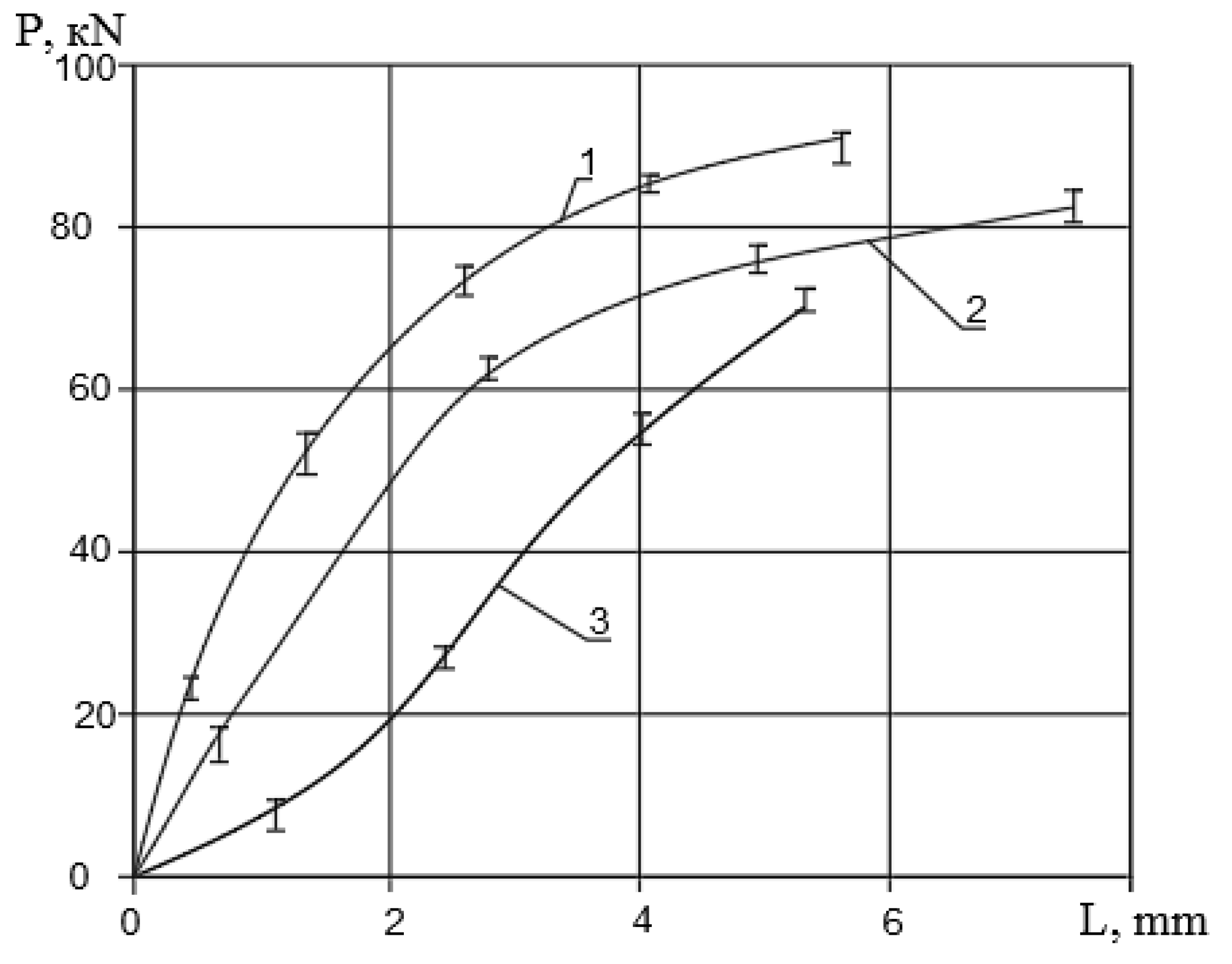
The energy-power parameters of the process were measured on the experimental stand. Measurement results were recorded on a H115 light-beam oscilloscope with a TA-5 amplifying strain gauge. Resistance sensors are assembled according to a half-bridge circuit. The ring mesdose was calibrated with a reference dynamometer of DS-150 kN. The dependences of deformation forces P on the movement of the roll at the three stages of flange rolling are shown in Figure 9, where the maximum roll force is 92 kN. The deformation force did not exceed the nominal force of the experimental stand—150 kN. Figure 9 shows the experimental curves of the deformation force of the workpiece at three stages: 1—at the third stage of part rolling; 2—at the second stage of part rolling; 3—at the first stage of part rolling.
According to the results of the computer simulation of the rolling process, analysis was made of the effective strain values in the workpiece for all three stages (Figure 10) [24]. The highest value of effective strain is observed in the hollow of the flange in the second and third stages (up to 3.7). In this zone, the stress state is close to the state of non-uniform all-round compression, and therefore, discontinuity of the metal in this zone is unlikely. A relatively small effective deformation is observed near the lower base of the formed truncated cone in the first stage, as well as in the upper part of the flange after the third stage. In these zones, predominantly tensile stresses act, which can lead to the appearance of defects [25] in the form of cracks if we continue the process of rolling.
4. Discussion
The proposed promising, new method of the angular rolling of pipe workpiece provides a stable process for forming flange parts in the ratio of the main geometric dimensions, b/s ≤ 5.4 and l/s ≤ 3.8, with a relative elongation of the workpiece metal of more than 30%. Cold angle rolling expands the nomenclature of the studied type of flanged parts and allows us to consider the promising technology of angle rolling with variable angles of the rolling roll at three stages, especially in small-scale production.
Numerical calculations in the program package DEFORM 3D made it possible to evaluate the formation of flange relief at any time, as well as to establish a rational range of angles of dip of the rollers at all stages of flange part shaping. For the first stage, β1 is 25° ≤ β1 ≤ 35°; the values of angles β2 in the second stage are 10° ≤ β2 ≤ 20°; and the range of angles α in the third stage is 45° ≤ α ≤ 75°.
The results of the experiments and computer simulation show that the technology of corner rolling in three stages eliminates a number of disadvantages of the known methods of metal forming in obtaining the type of parts being investigated, i.e., avoiding the loss of stability of the workpiece and overcoming a number of defects in the form of sinks, fractures, folds. Additionally, the creation of favorable conditions for the flow of metal and the elimination of the causes of defects by changing the angle of inclination of the roll increases the plasticity resource of the workpiece in areas with predominant tensile stresses.
Author Contributions
Kononov P.K.—paper writing, computer simulation in the DEFORM-3D software package, statistical data processing, conducting full-scale experiments. Ignatiev S.I.—interpretation of the obtained results, editing. Kononova I.K.—review of publications on the topic of the article, writing—review and editing. Levashov D.L.—translation of the article into English, Illustrations for the article. All authors have read and agreed to the published version of the manuscript.
Funding
This research was funded by Saint-Petersburg Mining University.
Institutional Review Board Statement
Not applicable.
Informed Consent Statement
Not applicable.
Data Availability Statement
Not applicable.
Conflicts of Interest
The authors declared no potential conflict of interest with respect to the research, authorship, and/or publication of this article.
References
- Kovka and Shtampovka S. Goryachaya Shtampovka; Semenov, E.I. (Ed.) Mashinostroenie: Moscow, Russia, 1986; p. 592. [Google Scholar]
- Kolikov, A.P.; Romancev, B.A. Teoriya Obrabotki Metallov Davleniem; MISIS: Moscow, Russia, 2017. [Google Scholar]
- Maksarov, V.V.; Olt, J. Dynamic stabilization of machining process based on local metastability in controlled robotic systems of CNC machines. J. Min. Inst. 2017, 226, 446–451. [Google Scholar]
- Milyaev, A.F. (Ed.) Foundry: Textbook Manual; Magnitogorsk MGTU: Moscow, Russia, 2005; p. 204. [Google Scholar]
- Tekhnologiya Konstrukcionnyh Materialov: Uchebnik Dlya Vuzov; Yu, M. (Ed.) Baron: St. Petersburg, Russia, 2012. [Google Scholar]
- Fedorova, L.V.; Ivanova, Y.S.; Voronina, M.V. Improvement of threaded joint reliability by means of electromechanical processing. J. Min. Inst. 2017, 266, 456–461. [Google Scholar]
- Aksenov, L.B.; Kunkin, S.N. 2016 Development of rotary forging machines: From idea to additive technologies Sciences of Europe, Praha, Czech Republic. Sci. Eur. 2016, 7, 4–11. [Google Scholar]
- Plancak, M.E.; Vilotic, D.Z.; Stefanovic, M.C.; Movrin, D.Z.; Kacmarcik, I.Z. Orbital forging—A possible alternative for bulk metal forming. J. Trends Dev. Mach. Assoc. Technol. 2012, 16, 35–38. [Google Scholar]
- Deng, X.B.; Hua, L.; Han, X.H. Numerical and experimental investigation of cold rotary forging of a 20CrMnTi alloy spur bevel gear. Mater. Des. 2011, 32, 1376–1389. [Google Scholar] [CrossRef]
- Winiarski, G.; Bulzak, T.; Wójcik, Ł.; Szala, M. Numerical Analysis of a Six Stage Forging Process for Producing Hollow Flanged Parts from Tubular Blanks. Adv. Sci. Technol. 2020, 14, 201–208. [Google Scholar] [CrossRef]
- Jin, Q.; Gu, Z.; Hua, J. Preform designing approach in cold orbital forging of flange gear. Adv. Mech. Eng. 2018, 10, 1–7. [Google Scholar] [CrossRef] [Green Version]
- Aksenov, L.B.; Kunkin, S.N. The Combined Cold Axial Rotary Forging of Thick Hollow Flanges. In Advances in Mechanical Engineering. Lecture Notes in Mechanical Engineering; Springer: Cham, Germany, 2017. [Google Scholar]
- Maksarov, V.V.; Efimov, A.E.; Golikov, T.S. Treatment of titanium alloys based on preliminary plastic impact. Key Eng. Mater. 2020, 836, 63–70. [Google Scholar] [CrossRef]
- Munshi, M.; Shah, K.; Cho, H.; Altan, T. 2005 Finite element analysis of orbital forming used in spindle/inner ring assembly. In Proceedings of the 8th ICTP 2005 International Conference on Technology of Plasticity, Verona, Italy, 9–13 October 2005. [Google Scholar]
- Vostrov, V.N.; Kononov, P.V. Finite-element simulation of flanging in the DEFORM 3D software package. Russ. Metall. Met. 2016, 5, 461–466. [Google Scholar] [CrossRef]
- Mishin, V.V.; Shishov, I.A. Investigation of deformation and fracture for thin beryllium foils under static loading by external pressure. Mater. Phys. Mech. 2018, 36, 100–113. [Google Scholar]
- Schipachev, A.M.; Samigullin, G.K.; Verzhbitskiy, K.D. Increasing service life of chuck unit of tank during cyclic loading. J. Phys. Conf. Ser. 2018, 1, 359–370. [Google Scholar]
- Bevza, V.F.; Grusha, V.P.; Krasnyi, V.A. Use of directional solidification for improving tubular workpiece quality of different cast irons. Metallurgist 2018, 62, 521–531. [Google Scholar] [CrossRef]
- Nosov, V.V.; Shipachev, A.M.; Palaev, A.G.; Grigorev, E.V. Quality assurance of sheets rolling on the basis of modeling the destruction process, plastic restructuring the structure of the material of the slab and the acoustic emissions parameters. J. Phys. Conf. Ser. 2020, 1431, 1136–1141. [Google Scholar] [CrossRef]
- Chupin, S.A.; Bolobov, V.I.; Jahr, A.; Heckmann, K.J. Study of the effect of thermomechanical processing of the cutter bit body material on its wear rate Innovation-Based Development of the Mineral Resources Sector: Challenges and Prospects. In Proceedings of the 11th Conference of the Russian-German Raw Materials, Potsdam, Germany, 7–8 November 2018; pp. 265–272. [Google Scholar]
- Vostrov, V.N.; Kononov, P.V. Method of rolling flanges on tubular blanks. RUS Patent 2,499,648, 27 November 2013. [Google Scholar]
- Chupin, S.A.; Bolobov, V.I. The investigation of the influence of thermomechanical treatment of the material of rotary cutter bit toolholders on its hardness. IOP Conf. Ser. Mater. Sci. Eng. 2017, 177, 012062. [Google Scholar] [CrossRef]
- Schipachev, A.M. Optimum Conditions of Turning and Surface Plastic Deformation Determination Taking into Account Technological Heredity. J. Phys. Conf. Ser. 2018, 10, 1118–1123. [Google Scholar]
- Kononov, P.; Ignatiev, S.; Tanacheva, T.; Tretyakova, Z.; Levashov, D. Numerical estimation of the plastically strain state of flange joints. Mater. Proc. 2020, 30, 532–537. [Google Scholar] [CrossRef]
- Kolbasnikov, N.G.; Mishin, V.V.; Shishov, I.A.; Matveev, M.A.; Korchagin, A.M. Surface-crack formation in the manufacture of microalloyed steel pipe. Steel Transl. 2016, 46, 665–670. [Google Scholar] [CrossRef]
Figure 1.
Axisymmetric parts with flanges.

Figure 2.
Sketch of the Flange part.

Figure 3.
Technological capabilities of the process of the cold metal forming of parts with flanges: 1—a curve limiting the area of the axial rotary forging the flanging scheme; 2—a curve limiting the area of rolling according to the scheme of rotary forging; 3—a curve limiting the area of rolling according to the scheme of angular rolling; 4—a curve limiting the area of manufacturing flange parts according to the radial extrusion scheme; and 5—a curve limiting the area of flange parts production according to the cross wedge rolling scheme.

Figure 4.
Finite element (FE) simulation of the cold angular rolling of a flange part.

Figure 5.
The sequence of flange part formed by angular rolling: (a–c) the first, second, and third stages of shaping.
Figure 5.
The sequence of flange part formed by angular rolling: (a–c) the first, second, and third stages of shaping.

Figure 6.
Comparison of computer and physical simulation forms for the angular rolling of a flange part at the rational angles of dip of rolling rolls: (a)—the first stage of rolling; (b)—the second stage of rolling; (c)—the third stage of rolling.
Figure 6.
Comparison of computer and physical simulation forms for the angular rolling of a flange part at the rational angles of dip of rolling rolls: (a)—the first stage of rolling; (b)—the second stage of rolling; (c)—the third stage of rolling.

Figure 7.
The working area of the experimental stand on the basis of lathe DIP 300 (1M63).

Figure 8.
The finished part.

Figure 9.
Dependences of deformation forces P at the obtained confidence intervals on the movement L of the work roll during part rolling.
Figure 9.
Dependences of deformation forces P at the obtained confidence intervals on the movement L of the work roll during part rolling.

Figure 10.
Distribution field of effective strain values of the workpiece at three stages of its deformation: (a)—the first stage of rolling out, angle of rolls β1 = 30°; (b)—the second stage, β2 = 15°; (c)—the third stage, α = 45°.
Figure 10.
Distribution field of effective strain values of the workpiece at three stages of its deformation: (a)—the first stage of rolling out, angle of rolls β1 = 30°; (b)—the second stage, β2 = 15°; (c)—the third stage, α = 45°.


Table 1.
The chemical composition of brass in mas.% L68 (according to GOST 15527-2004), analogue American C26800, German CuZn33.
Table 1.
The chemical composition of brass in mas.% L68 (according to GOST 15527-2004), analogue American C26800, German CuZn33.
| Alloy | Cu | Fe | P | Pb | Sb | Bi | Zn | Impurities |
|---|---|---|---|---|---|---|---|---|
| L68 | 67-70 | 0.1 | 0.001 | 0.03 | 0.005 | 0.002 | rest | 0.3 |
Publisher’s Note: MDPI stays neutral with regard to jurisdictional claims in published maps and institutional affiliations. |
© 2021 by the authors. Licensee MDPI, Basel, Switzerland. This article is an open access article distributed under the terms and conditions of the Creative Commons Attribution (CC BY) license (http://creativecommons.org/licenses/by/4.0/).
Share and Cite
MDPI and ACS Style
Kononov, P.; Ignatiev, S.; Levashov, D.; Kononova, I. Angular Rolling of the Hollow Flanges of Pipe Joints. Metals 2021, 11, 166. https://0-doi-org.brum.beds.ac.uk/10.3390/met11010166
AMA Style
Kononov P, Ignatiev S, Levashov D, Kononova I. Angular Rolling of the Hollow Flanges of Pipe Joints. Metals. 2021; 11(1):166. https://0-doi-org.brum.beds.ac.uk/10.3390/met11010166
Chicago/Turabian StyleKononov, Pavel, Sergey Ignatiev, Dmitry Levashov, and Irina Kononova. 2021. "Angular Rolling of the Hollow Flanges of Pipe Joints" Metals 11, no. 1: 166. https://0-doi-org.brum.beds.ac.uk/10.3390/met11010166
Note that from the first issue of 2016, this journal uses article numbers instead of page numbers. See further details here.