
Microstructural and Mechanical Characterization of W-CuCrZr Joints Brazed with Cu-Ti Filler Alloy


Materials Science and Engineering Area, ESCET, Rey Juan Carlos University, C/Tulipán s/n, 28933 Móstoles, Madrid, Spain
*
Author to whom correspondence should be addressed.
Metals 2021, 11(2), 202; https://0-doi-org.brum.beds.ac.uk/10.3390/met11020202
Submission received: 18 December 2020
/
Revised: 18 January 2021
/
Accepted: 20 January 2021
/
Published: 22 January 2021
(This article belongs to the Special Issue Mechanical Characteristics of Brazed Joints in Metallic Materials)
Abstract
:The determination of the mechanical properties of a brazed joint is an important factor to reach the metallurgical level of a joint development. This paper evaluates the mechanical properties, and its correlation with the joint microstructure, of a W-CuCrZr joint brazed in a high vacuum furnace using 80Cu-20Ti flexible filler material in tape form. This joint is meant to be implemented in the divertor application in future fusion power plants. Main experimental parameters were a brazing temperature of 960 °C and a dwell time of 10 min. The microstructure of the joint was constituted by Cu solid solution and Cu4Ti phases. This last phase was distributed in the W-braze interface. Mechanical properties were evaluated by means of Vickers microhardness and mechanical tests by applying pure shear loads. The microhardness profile of the brazed joint indicated that W remained with the as-received hardness but CuCrZr base material was softened after the brazing procedure. Shear strength of 96 ± 15 MPa was obtained for the brazed joint and fracture propagated at the W-braze interface.
1. Introduction
The continuous development of new materials in the industry makes new joining processes necessary. For a proper determination of the joint properties, a quality assurance process, which ensures that the joint covers all the requirements of the joint service conditions, is necessary. This process is usually developed by levels of joinability, where the first one is the consecution of a full metallic continuity along the joint interface. That ensures, in the case of brazing process, that the filler presents an acceptable wetting in the base materials and completely fills the joint clearance. The second level evaluates the joint from the mechanical point-of-view and ensures that the strength of the joint is within the design criteria of the brazed piece/component. To reach this level, the examination of the microstructure must be analyzed to correlate it with the mechanical properties, where the presence of brittle intermetallic compounds, diffusion layers, or base material affectation could have a strong influence on the mechanical properties [1,2].
This paper evaluates the second level of the joint development between tungsten and a copper alloy by measuring the mechanical properties of a brazed joint and its correlation with the joint microstructure using Cu-20Ti filler. This joint is thought to be implemented in the first wall or divertor component in future fusion power plants [3,4]. Tungsten, in these components, acts as a plasma facing layer, where its refractory nature helps to withstand the complex environment (high thermal loads, particle sputtering). On the other hand, copper alloy pipes (Cu-Cr-Zr alloy) are in direct contact with tungsten to extract the heat [5].
The heterogeneous nature of the joint along with the refractory character of one base material makes, in this case, a complex joint design that must be overcome. Although in a brazing process, the metallic continuity is fundamentally reached by the filling process of the joint clearance by the molten filler, some defects could be avoided by other mechanisms such as plastic deformation or diffusion mechanism. Those mechanisms include a lack of chemical interactions and low diffusion rates besides the mismatch in the different coefficient of thermal expansion (CTE).
The filler material must be chosen carefully in order to fulfill the general requirements such as high spreading capabilities, chemical compatibility or specific requirements, which in this case includes high solidus temperature, high thermal conductivity and capability to accommodate residual stresses as a consequence of the mismatch in the CTE of both base materials. Copper-titanium alloys, especially those richer in copper, are candidates to act as filler due to the high ductility of copper along with the active wetting behavior of titanium [6,7].
Different authors have tried to join W to copper with different results. For example, Li et al. used different stress relief interlayers obtaining high strength joints. However, brazing temperature was high (~1000 °C) considering the effect of this parameter in the base material properties [8,9]. Direct hot pressing technique was used for Jiang et al. also at temperatures of 1000 °C [10]. In addition, Greuner et al. and Richou et al. tried to relieve the residual stress generated during the cooling stage of the process by using a functionally graded interlayer. The results measured by High Heat Flux (HHF) tests showed some problems when a high number of cycles were applied [11,12].
This paper aims to determine the brazeability and mechanical properties of W-CuCrZr joints by using Cu-Ti filler material. Therefore, the microstructure of the joint was elucidated, using a SEM microscope, and correlated with the mechanical properties obtained by means of microhardness and pure shear strength tests.
2. Materials and Methods
2.1. Materials
The base materials used for the brazing tests were polycrystalline tungsten supplied by Plansee (Reutte, Austria) and CuCrZr alloy supplied by KME (Osnabrück, Germany) with chromium ranges between 0.2 and 1.2 wt.% and zirconium ranges between 0.05 and 0.25 wt.%. Cu-Ti fillers for joining W to CuCrZr were fabricated in form of flexible tapes. Therefore, the first step is the mill mixing of pure powders (Cu and Ti) for 2 h using a ball mill device Ancaja (Orto Alresa, Daganzo de Arriba, Spain) at 1.66 s−1. Both metallic powders were supplied by Cymit Química (Barcelona, Spain), copper powders, −325 mesh, +325 mesh, >99% purity and titanium powders, −200 mesh, and 99.95%. For the manufacturing of flexible tapes, the powders were mixed with an organic binder (powder/binder weight ratio: 95/5) and laminated using two anti-adherent films to obtain tapes with a thickness of around 150–200 µm. The binder used was polypropylene carbonate (PPC, QPAC 40) supplied by Empower Materials (New Castle, UK) in pellets form.
2.2. Brazing Tests
A high vacuum furnace (Nabertherm P330, Lilienthal, Germany) was used for the brazing tests at a residual pressure of 10−6 mbar. Prior to the brazing, samples of both base materials of 6 mm × 6 mm in area were grounded down with 4000 grit silicon carbide paper. Two different thicknesses of base material were used: 2 mm for the microstructural and microhardness tests, and 5 mm for the shear tests. The brazing conditions were 50 °C over the liquidus temperature of the filler alloy (960 °C) and dwell times were 10 min for all cases. This temperature ensures the correct melting and spreading of the alloy in the clearance according to previous works carried out with Cu-Ti alloys [13]. The heating and cooling rates were 5 °C/min.
2.3. Characterization Techniques
A scanning electron microscope (SEM, S3400 Hitachi, Chiyoda, Japan) equipped with energy dispersive X-ray spectroscopy (EDS, Bruker, Billerica, MA, USA) microanalysis and optical microscopy (OM, Leica, Wetzlar, Germany) was used for the microstructural examinations. Samples for metallographic analysis were perpendicular cut to the joint interface. The exposed surface was ground down to 4000 grit silicon carbide paper, polished with a diamond suspension of 1 um particle, and finally cleaned with isopropanol. In some cases, joints were etched to reveal their microstructure with an etchant solution ASTM nr. 30 (ammonia and hydrogen peroxide reactants).
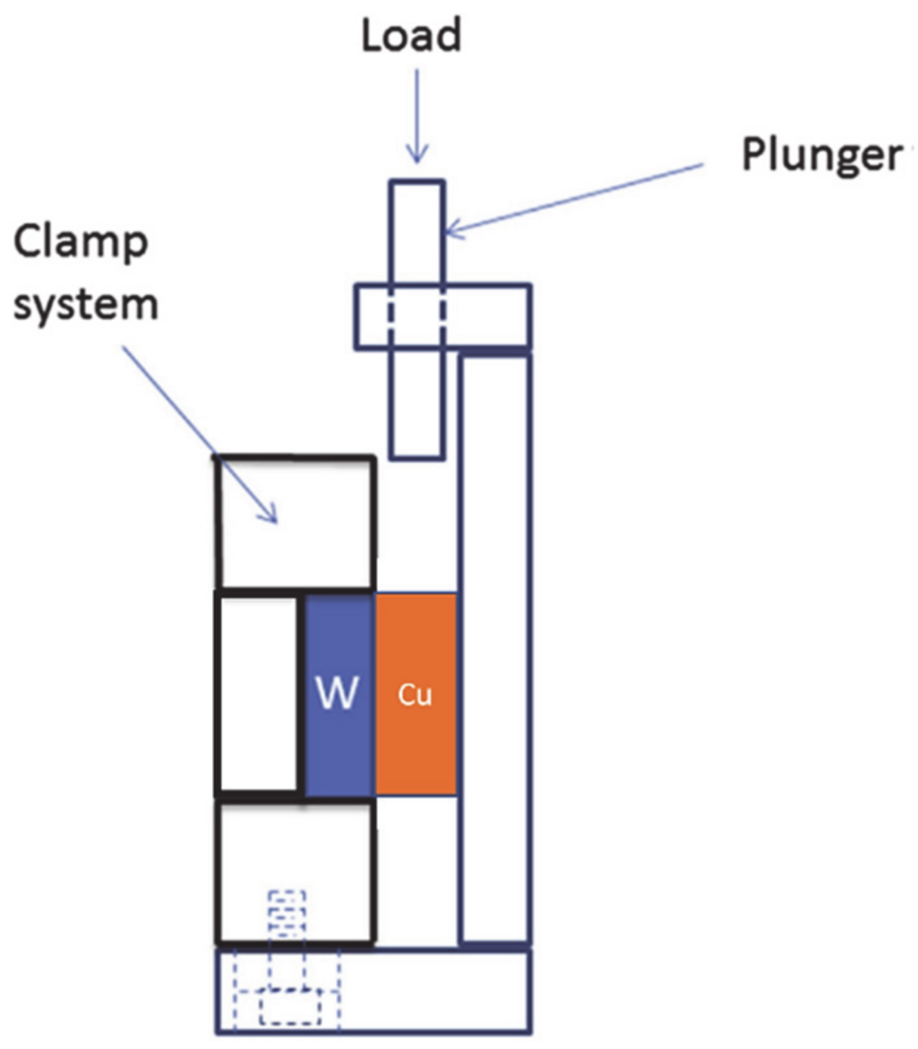
To evaluate the effect caused by the brazing process on the base materials, microhardness profiles across the joint were obtained by MHV-2 equipment (Shimadzu, Kioto, Japan). A load of 1 N was applied for 30 s from copper alloy to W and three indentations were made for each microhardness value. The strength of the joint was evaluated with a UTM machine Z100 (Zwick, Ulm, Germany) using a special shear fixture designed for that purpose shown in Figure 1. Three samples were measured to obtain the mean value along with its standard deviation. The objective is to avoid the misalignment of the joint interface during the tests and to ensure the pure shear stress of the joint. Pure shear allows obtaining information about the joint interface strength when the load is distributed, at least theoretically, homogeneously through the interface plane. This configuration is desired when the strength of the base metals are higher than the joint interface [14,15,16,17,18]. The shear tests were carried out at a velocity of 1 mm/min.
3. Results
3.1. Microstructural Characterization of the Joint
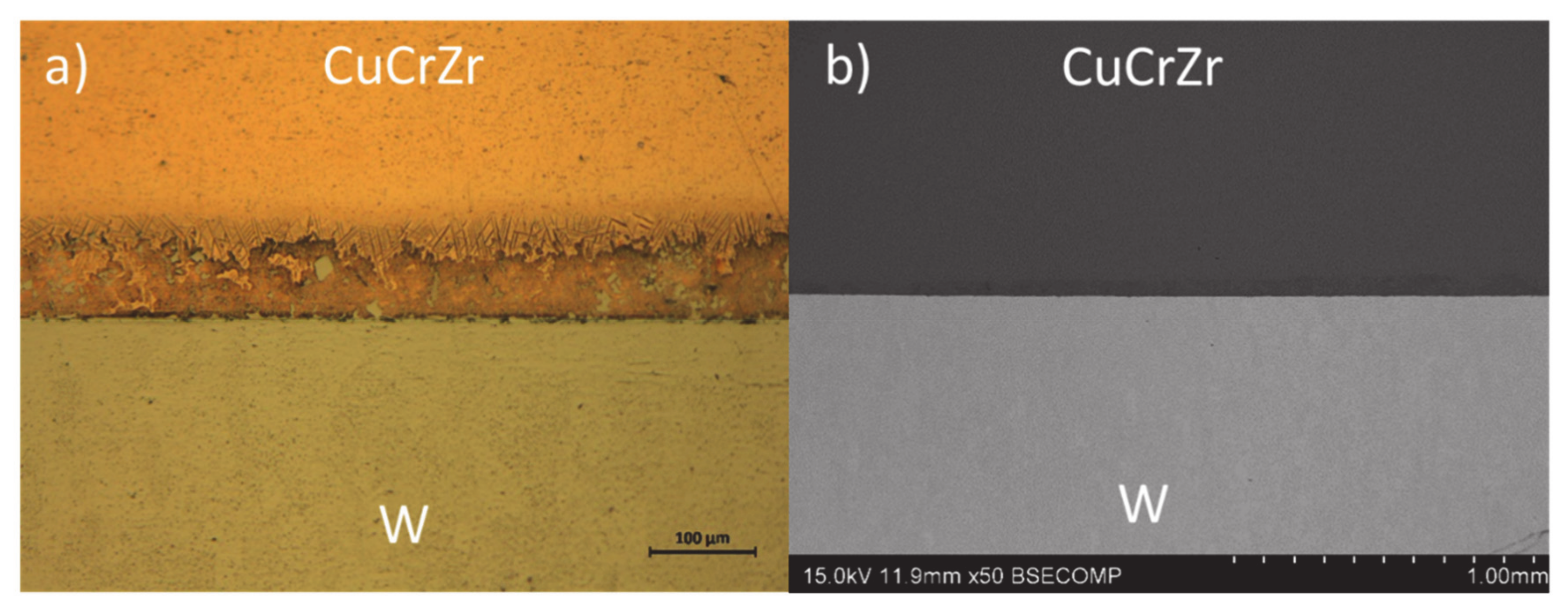
Figure 2a,b shows general micrographs of the W-CuCrZr joints obtained by optical microscopy and SEM. They confirmed that the first step of the joint development has been achieved. There is no sign of wetting or porosity defects in any of the interfaces reaching 100% of metallic contact.
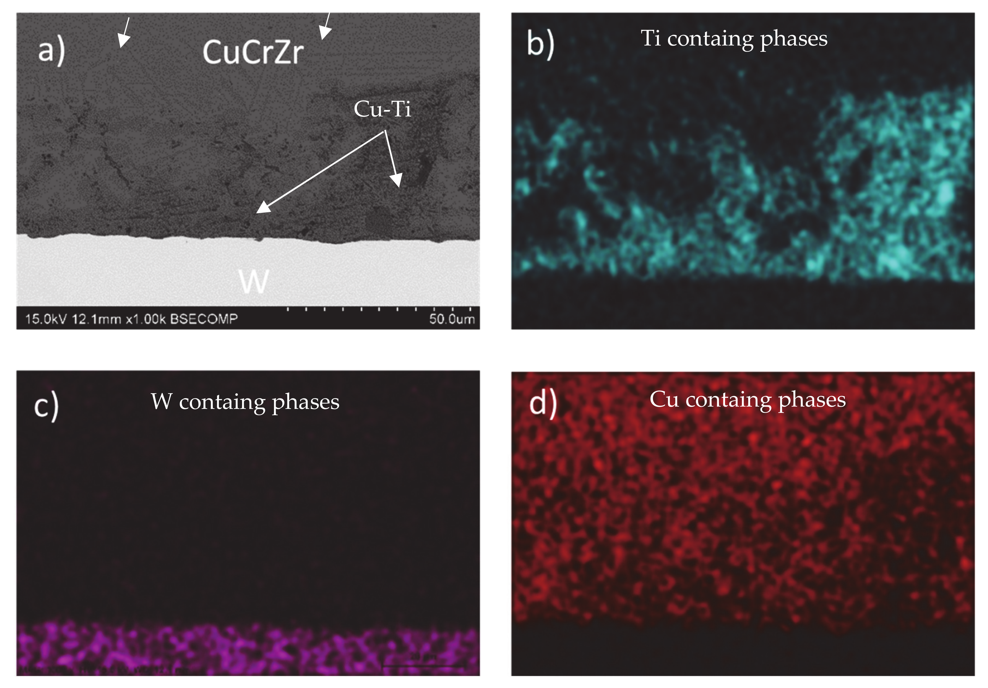
A deeper characterization analysis was carried out in Figure 3a. It shows a micrograph of the braze zone at higher magnification, where the heterogeneous microstructure that constitutes the braze can be observed. According to the distribution of the joint main elements, the phase containing Ti-Cu with a heterogeneous distribution is in contact with the W interface (Figure 3a). This phase shows a darker contrast in the SEM image and penetrates randomly into the braze zone. There is no sign of diffusion or dilution phenomena between tungsten and the braze elements at the interface (Figure 3b–d). This fact is associated with the lack of chemical interaction or diffusion phenomena of tungsten at the brazing temperature. Finally, the rest of the braze is constituted by copper, where the presence of acicular structures could be vaguely observed inside this phase in Figure 3a (arrowed) and more clearly in Figure 4b.
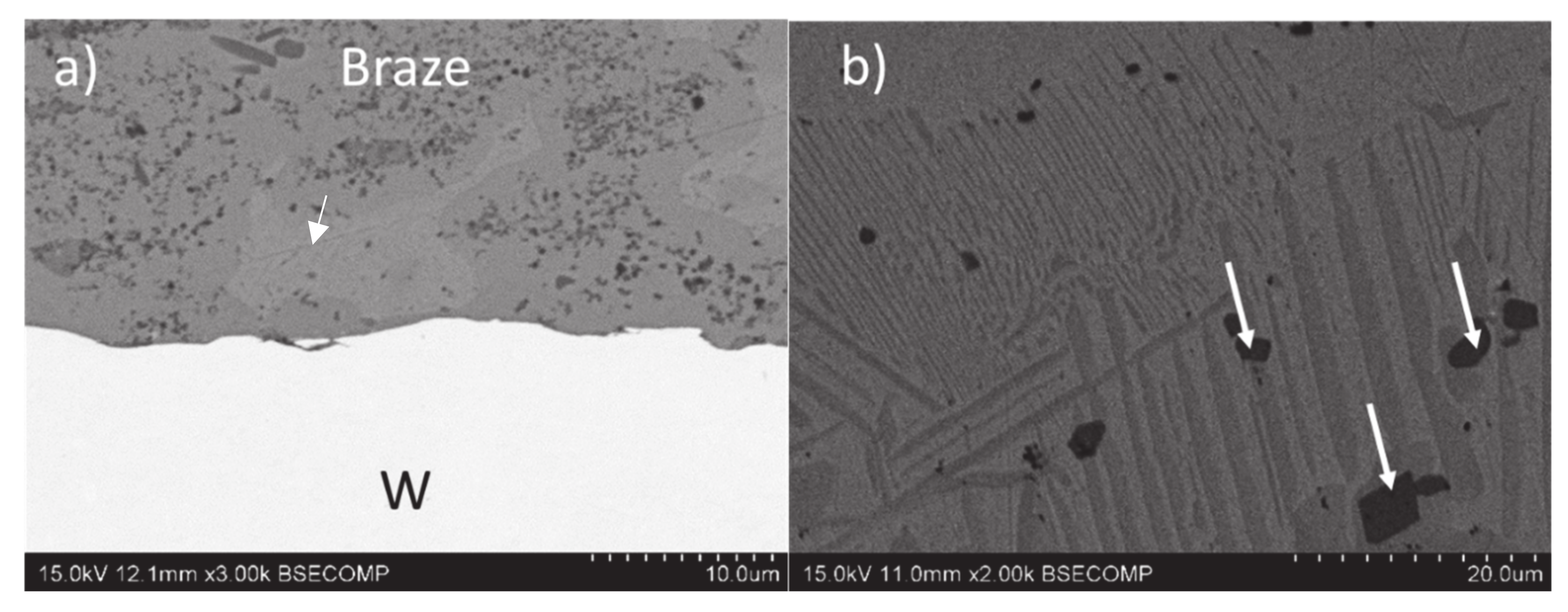
A deeper analysis of the joint interfaces is shown in Figure 4. The W-braze interface is characterized by the majority presence of the previously studied phase containing Ti-Cu, showing darker tonality at the back-scattered electron detector (BSE) image (Figure 4a). Inside this phase, a fine dispersion of homogeneously distributed precipitates can be observed. According to the semiquantitative EDS microanalysis, the phase contains 80Cu-20Ti in at. %, which agrees with the thermodynamically stable Cu4Ti phase detected in other works that studied the solidification of Cu-Ti alloys or fillers with similar compositions [6,13]. Besides the previous phase, a small presence of Cu solid solution phase, arrowed in Figure 4a showing lighter tonality, is also observed.
On the other hand, the study of the braze zone (Figure 4b) shows the presence of a eutectic-like microstructure formed by the copper rich phase (90Cu-8Ti-1Zr-1Cr in at. % by EDS microanalysis) and the 80Cu-20Ti phase. The distribution of the phases changes at the bottom part of the joint, where the presence of the acicular structures described in Figure 3a could be clearly observed. In addition, dark contrast precipitates with a composition of 63Cu-37Ti in at. % have also been detected (arrowed in Figure 4b).
3.2. Mechanical Characterization
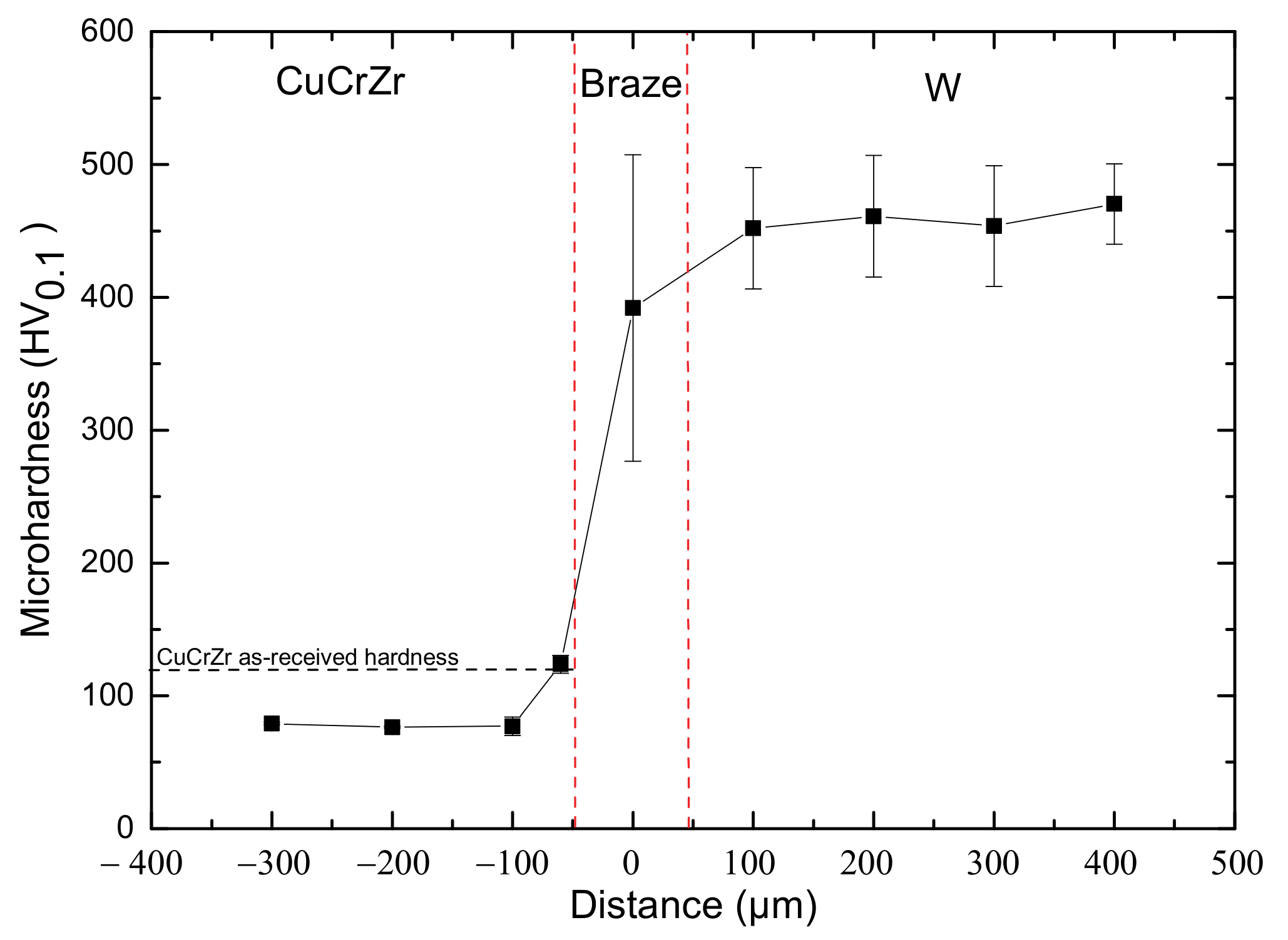
The hardness profile of W-CuCrZr joints is shown in Figure 5. The mean measured value of the CuCrZr base material after the brazing process is 77 HV0.1 versus 120 HV0.1 in the as-received conditions. The softening process is associated with a partial solubilization of the hardening precipitates, grain growth, or recrystallization process at the brazing temperature. Brazing temperatures situate the copper alloy in the solubilization field and could solubilize some alloying elements [19]. The subsequent slow cooling rate used is not enough to induce precipitation [20]. The application of quenching processes from the brazing temperature and subsequent aging treatment should be considered to avoid this phenomenon. However, high cooling rates could induce higher residual stress in the joint due to the mismatch in the CTE of the base materials. Therefore, the benefit of the application of a recovery process for the base material hardness should be balanced with the detrimental effect in the joint mechanical properties.
The high scatter value of the braze hardness is the consequence of the heterogeneous microstructure studied in the previous section. Depending on the phase indented, the hardness value varied but the main presence of the Cu4Ti phase, associated to high hardness values [21], makes an average hardness of the braze close to 400 HV0.1.
Regarding the tungsten base material, the as-received hardness has not been modified by the brazing process and corresponds to the hardness of polycrystalline tungsten found in the bibliography [22]. Because of the refractory nature of this base material, the temperatures reached are not high enough to cause recrystallization, grain growth process, or diffusion phenomena—processes which could modify the hardness of the material.
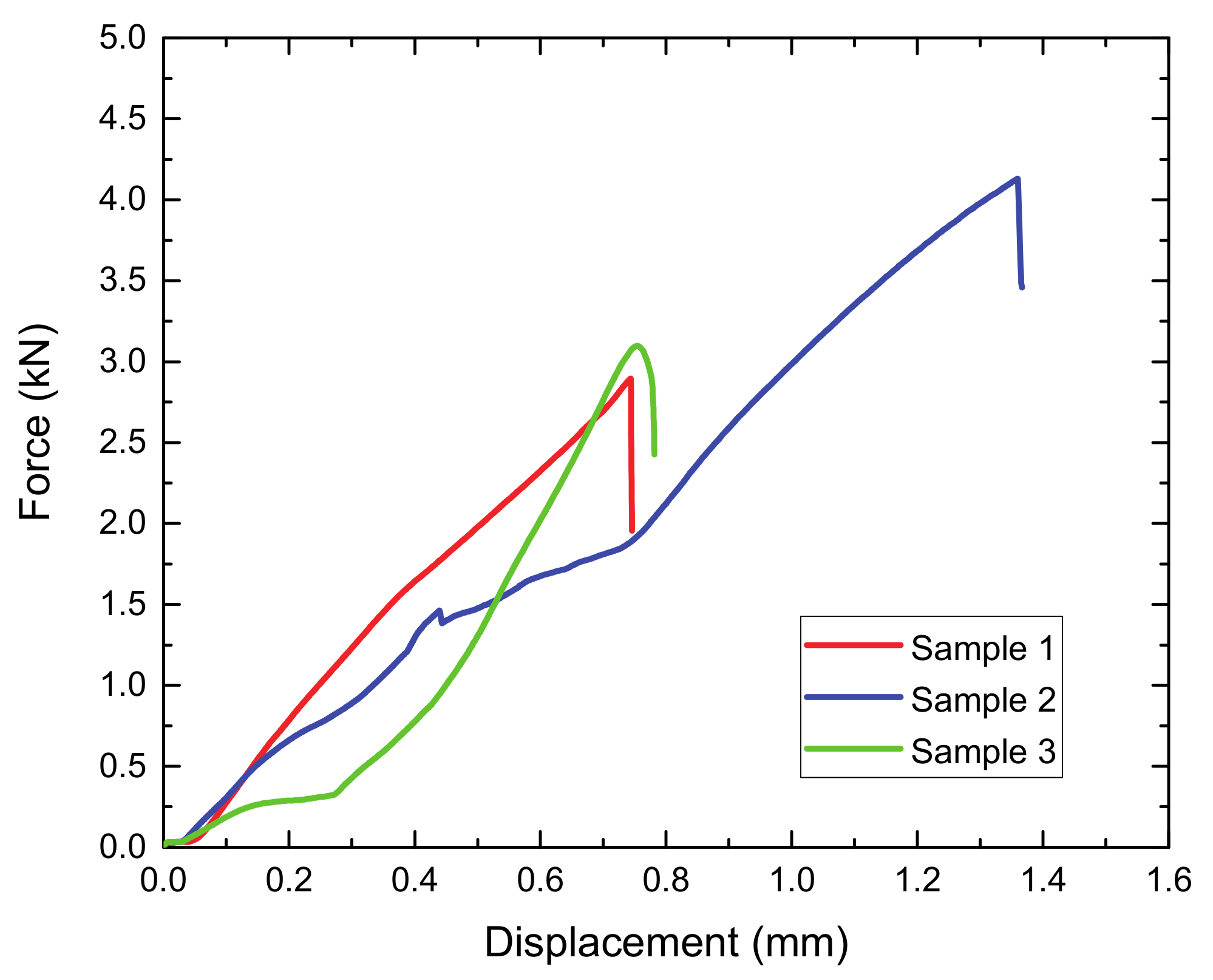
The force–displacement curves of the shear strength tests are shown in Figure 6. Two samples withstand 3 kN and the third one 4 kN. Fracture occurred with no apparent plastic deformation at displacements of 0.6 and 1.3 mm, respectively. The average shear strength was 96 ± 15 MPa, which is in the range of other works using the brazing technique. For example, Peng et al. also used Cu-Ti filler alloy, but using Ti richer contents, the filler applied to W-CuCrZr joints obtained 96 ± 18 MPa [23]; and Singh et al. obtained a strength of 22 MPa in the W-CuCrZr joint using a pure Cu interlayer when they joined a multilayered component [24].
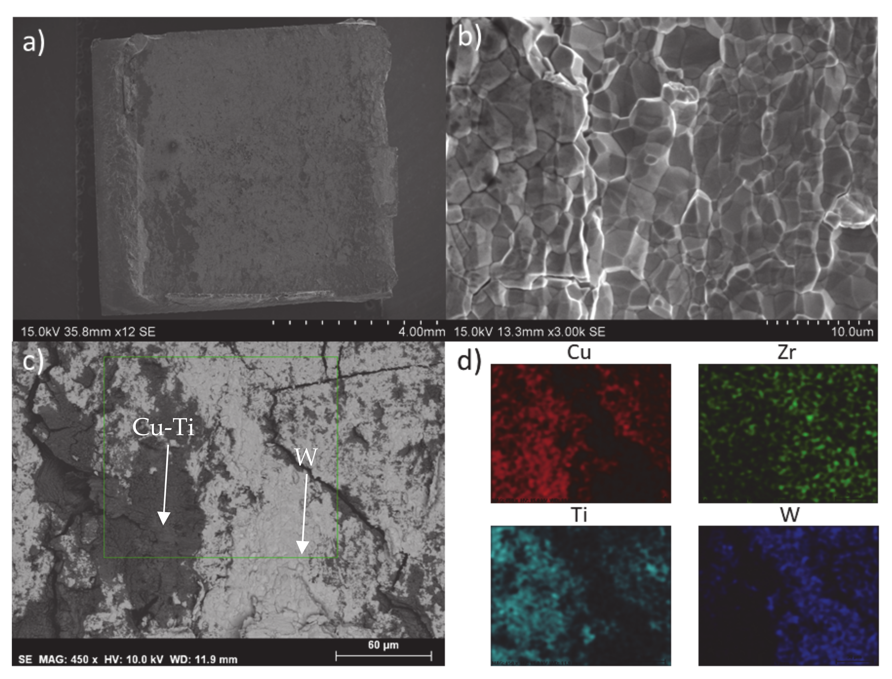
The analysis of the fracture surface of the CuCrZr side at low magnification confirms that plastic deformation has not occurred (Figure 7a). Furthermore, the fractography image at higher magnification of the tungsten side shows a brittle intergranular fracture mechanism. There is no presence of filler in this surface due to the fact that fracture has propagated in this base material in which tungsten grains can be observed (Figure 7b).
Figure 7c,d shows the fracture surface of the CuCrZr obtained by the back-scattering detector and EDS elemental distribution map of the selected area, respectively. In this case, the presence of Cu-Ti and W phases were detected, arrowed in Figure 7c and visible at the elemental mapping distribution in Figure 7d. This could be an indication that fracture propagated along the W-braze interface following the Cu4Ti brittle phase or through the tungsten base material that remained adhered to the CuCrZr base material. This fact shows the good adhesion properties of the braze.
4. Conclusions
The mechanical evaluation of the W-CuCrZr joint using Cu-20Ti filler material shows that the second level of the joint development was achieved. This achievement is the result of the high wettability properties showed by the selected filler that has formed a defect free braze after the brazing process. The microstructure of the joint was constituted by Cu solid solution and Cu4Ti phases. This last phase was distributed in the W-braze interface.
Tungsten base material hardness was not modified during the brazing process. However, softening of CuCrZr occurred associated to a dissolution process of the hardening precipitates. The strength of the joint measured in shear mode is 96 MPa. Fracture followed a brittle intergranular mechanism, where the presence of braze and tungsten material in the CuCrZr side indicated that crack has propagated along the CuCrZr-braze interface or in the tungsten material in the proximity of the interface.
Author Contributions
Writing—original draft, J.d.P. and M.S.; methodology, J.d.P. and M.S.; investigation J.d.P. and D.S.; supervision, M.S. and A.U.; funding acquisition, M.S. and A.U.; project administration, M.S. and A.U.; validation, D.S.; formal analysis D.S.; conceptualization, A.U.; visualization, A.U. All authors have read and agreed to the published version of the manuscript.
Funding
This work has been carried out within the framework of the EUROfusion Consortium and has received funding from the Euratom research and training programme 2014−2018 and 2019–2020 under grant agreement No 633053. The views and opinions expressed herein do not necessarily reflect those of the European Commission. The authors would also like to acknowledge the Community of Madrid in the frame work of the Multiannual Agreement with the Rey Juan Carlos University in line of action 1, “Encouragement of Young PhD students investigation” Project Ref. M 2168 Acronym DARUCEF.
Institutional Review Board Statement
Not applicable.
Informed Consent Statement
Not applicable.
Data Availability Statement
Data sharing not applicable.
Conflicts of Interest
The authors declare no conflict of interest.
References
- Ionel, O. Considerations on the Development of Brazed Joints Using Two Materials With Different Properties. J. Eng. Stud. Res. 2016, 18, 66–70. [Google Scholar] [CrossRef]
- Schwartz, M.M. Brazing; ASM International: Materials Park, OH, USA, 2003. [Google Scholar]
- Bonavolontà, U.; Bachmann, C.; Coccorese, D.; Di Gironimo, G.; Imbriani, V.; Marzullo, D.; Mazzone, G.; Vorpahl, C.; You, J.H. EU-DEMO divertor: Cassette design and PFCs integration at pre-conceptual stage. Fusion Eng. Des. 2020, 159, 111784. [Google Scholar] [CrossRef]
- Mozzillo, R.; Bachmann, C.; Aiello, G.; Marzullo, D. Design of the European DEMO vacuum vessel inboard wall. Fusion Eng. Des. 2020, 160, 111967. [Google Scholar] [CrossRef]
- Maviglia, F.; Albanese, R.; Ambrosino, R.; Arter, W.; Bachmann, C.; Barrett, T.; Federici, G.; Firdaous, M.; Gerardin, J.; Kovari, M.; et al. Wall protection strategies for DEMO plasma transients. Fusion Eng. Des. 2018, 136, 410–414. [Google Scholar] [CrossRef]
- De Prado, J.; Sánchez, M.; Ureña, A. Wettability study of a Cu-Ti alloy on tungsten and EUROFER substrates for brazing components of DEMO fusion reactor. Mater. Des. 2016, 99, 93–101. [Google Scholar] [CrossRef]
- De Prado, J.; Sánchez, M.; Ureña, A. Corrigendum to “Improvements in W-Eurofer first wall brazed joint using alloyed powders fillers”. Fusion Eng. Des. 2018, 128, 235. [Google Scholar] [CrossRef]
- Li, J.; Yang, J.F.; Chen, J.L. High heat load properties of actively cooled W/CuCrZr mock-ups by diffusion bonding with Ni or Ti interlayer. Fusion Eng. Des. 2011, 86, 2874–2878. [Google Scholar] [CrossRef]
- Jiang, D.; Long, J.; Cai, M.; Lin, Y.; Fan, P.; Zhang, H.; Zhong, M. Femtosecond laser fabricated micro/nano interface structures toward enhanced bonding strength and heat transfer capability of W/Cu joining. Mater. Des. 2017, 114, 185–193. [Google Scholar] [CrossRef]
- Jiang, D.; Long, J.; Han, J.; Cai, M.; Lin, Y.; Fan, P.; Zhang, H.; Zhong, M. Comprehensive enhancement of the mechanical and thermo-mechanical properties of W/Cu joints via femtosecond laser fabricated micro/nano interface structures. Mater. Sci. Eng. A 2017, 696, 429–436. [Google Scholar] [CrossRef]
- Greuner, H.; Zivelonghi, A.; Böswirth, B.; You, J.H. Results of high heat flux testing of W/CuCrZr multilayer composites with percolating microstructure for plasma-facing components. Fusion Eng. Des. 2015, 98–99, 1310–1313. [Google Scholar] [CrossRef] [Green Version]
- Richou, M.; Gallay, F.; Böswirth, B.; Chu, I.; Dose, G.; Greuner, H.; Kermouche, G.; Lenci, M.; Loewenhoff, T.; Maestracci, R.; et al. Performance assessment of thick W/Cu graded interlayer for DEMO divertor target. Fusion Eng. Des. 2020, 157, 111610. [Google Scholar] [CrossRef]
- De Prado, J.; Sánchez, M.; Urea, A. Development of Brazing Process for W-EUROFER Joints Using Cu-Based Fillers. Phys. Scr. 2016, 2016, 014022. [Google Scholar] [CrossRef]
- Rajendran, S.H.; Hwang, S.J.; Jung, J.P. Shear strength and aging characteristics of sn-3.0ag-0.5cu/cu solder joint reinforced with zro2 nanoparticles. Metals 2020, 10, 1295. [Google Scholar] [CrossRef]
- Wang, Z.; Xue, S.; Long, W.; Wang, B.; Wang, J.; Zhang, P. Effects of Extreme Thermal Shock on Microstructure and Mechanical Properties of Au-12Ge/Au/Ni/Cu Solder Joint. Metals 2020, 10, 1373. [Google Scholar] [CrossRef]
- De Prado, J.; Sánchez, M.; Ureña, A. Improvements in W-Eurofer first wall brazed joint using alloyed powders fillers. Fusion Eng. Des. 2017, 124, 1082–1085. [Google Scholar] [CrossRef]
- Process, M. The Effect of Recrystallization on Creep Properties of. Metals 2020, 10, 1443. [Google Scholar]
- Qiu, D.; Gao, Z.; Ba, X.; Wang, Z.; Niu, J. Vacuum brazing of 55 vol.% sicp/zl102 composites using micro-nano brazing filler metal fabricated by melt-spinning. Metals 2020, 10, 1470. [Google Scholar] [CrossRef]
- Zhang, B.; Zhang, Z.G.; Li, W. Effects of thermo-mechanical treatment on microstructure and properties of Cu-Cr-Zr alloys. Phys. Procedia 2013, 50, 55–60. [Google Scholar] [CrossRef] [Green Version]
- Liu, H.; Xue, F.; Bai, J.; Sun, Y. Effect of heat treatments on the microstructure and mechanical properties of an extruded Mg95.5Y3Zn1.5 alloy. Mater. Sci. Eng. A 2013, 585, 261–267. [Google Scholar] [CrossRef]
- De Prado, J.; Roldán, M.; Sánchez, M.; Bonache, V.; Rams, J.; Ureña, A. Interfacial characterization by TEM and nanoindentation of W-Eurofer brazed joints for the first wall component of the DEMO fusion reactor. Mater. Charact. 2018, 142, 162–169. [Google Scholar] [CrossRef]
- De Prado, J.; Sánchez, M.; Wirtz, M.; Pintsuk, G.; Du, J.; Linke, J.; Ureña, A. Impact of thermal fatigue on W–W brazed joints for divertor components. J. Mater. Process. Technol. 2018, 252, 211–216. [Google Scholar] [CrossRef]
- Peng, S.; Mao, Y.; Min, M.; Xi, L.; Deng, Q.; Wang, G.; Wang, S. Joining of tungsten to CuCrZr alloy with Cu-TiH2-Ni filler and Cu interlayer. Int. J. Refract. Met. Hard Mater. 2019, 79, 31–36. [Google Scholar] [CrossRef]
- Singh, K.P.; Khirwadkar, S.S.; Bhope, K.; Patel, N.; Mokaria, P. Feasibility study on joining of multi-layered W/Cu-CuCrZr-SS316L-SS316L materials using vacuum brazing. Fusion Eng. Des. 2018, 127, 73–82. [Google Scholar] [CrossRef]
Figure 1.
Shear fixture used for the mechanical tests.

Figure 2.
General micrographs of the W-CuCrZr joint brazed with Cu-20Ti filler obtained by (a) Optical Microscopy and (b) SEM.
Figure 2.
General micrographs of the W-CuCrZr joint brazed with Cu-20Ti filler obtained by (a) Optical Microscopy and (b) SEM.

Figure 3.
(a) SEM micrograph of the W-CuCrZr brazed joint, (b–d) elemental distribution of Ti, W, and Cu in the joint, respectively.
Figure 3.
(a) SEM micrograph of the W-CuCrZr brazed joint, (b–d) elemental distribution of Ti, W, and Cu in the joint, respectively.

Figure 4.
SEM micrograph of the W-CuCrZr brazed joint at: (a) W-braze interface and (b) braze zone.

Figure 5.
Microhardness profile of the W-CuCrZr brazed joint across the braze.

Figure 6.
Load–displacement curve of the brazed joint shear tests.

Figure 7.
Fractographic images obtained by SEM of (a) CuCrZr and (b) tungsten side, (c) SEM-BSE image at the CuCrZr side, and (d) EDS elemental distribution map, respectively.
Figure 7.
Fractographic images obtained by SEM of (a) CuCrZr and (b) tungsten side, (c) SEM-BSE image at the CuCrZr side, and (d) EDS elemental distribution map, respectively.

Publisher’s Note: MDPI stays neutral with regard to jurisdictional claims in published maps and institutional affiliations. |
© 2021 by the authors. Licensee MDPI, Basel, Switzerland. This article is an open access article distributed under the terms and conditions of the Creative Commons Attribution (CC BY) license (http://creativecommons.org/licenses/by/4.0/).
Share and Cite
MDPI and ACS Style
de Prado, J.; Sánchez, M.; Swan, D.; Ureña, A. Microstructural and Mechanical Characterization of W-CuCrZr Joints Brazed with Cu-Ti Filler Alloy. Metals 2021, 11, 202. https://0-doi-org.brum.beds.ac.uk/10.3390/met11020202
AMA Style
de Prado J, Sánchez M, Swan D, Ureña A. Microstructural and Mechanical Characterization of W-CuCrZr Joints Brazed with Cu-Ti Filler Alloy. Metals. 2021; 11(2):202. https://0-doi-org.brum.beds.ac.uk/10.3390/met11020202
Chicago/Turabian Stylede Prado, Javier, María Sánchez, David Swan, and Alejandro Ureña. 2021. "Microstructural and Mechanical Characterization of W-CuCrZr Joints Brazed with Cu-Ti Filler Alloy" Metals 11, no. 2: 202. https://0-doi-org.brum.beds.ac.uk/10.3390/met11020202
Note that from the first issue of 2016, this journal uses article numbers instead of page numbers. See further details here.