
Flotation Separation of Chalcopyrite and Molybdenite Assisted by Microencapsulation Using Ferrous and Phosphate Ions: Part II. Flotation

Abstract
:1. Introduction
2. Materials and Methods
2.1. Mineral Samples
2.2. Microencapsulation Treatment
2.3. Flotation Tests
2.4. Contact Angle Measurements
3. Results and Discussion
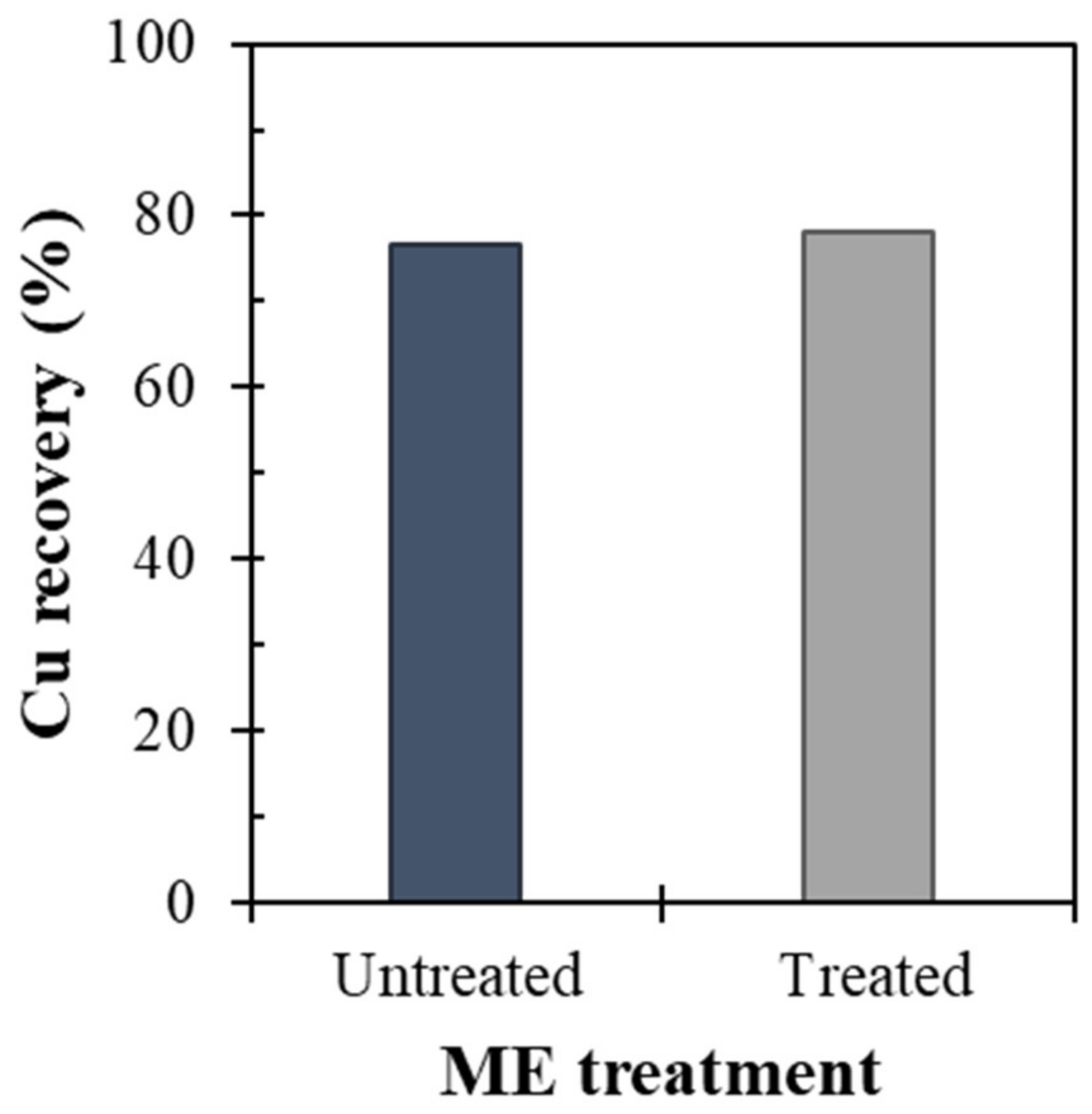
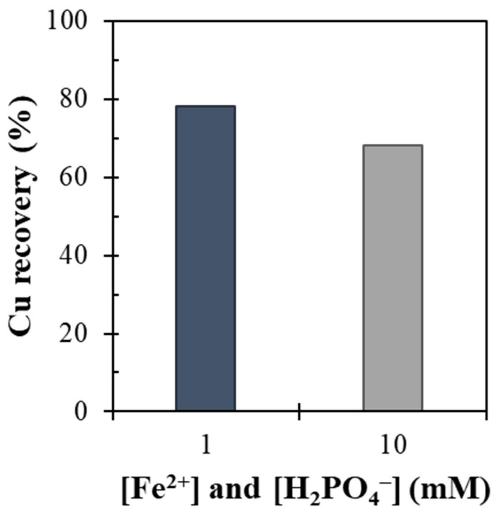
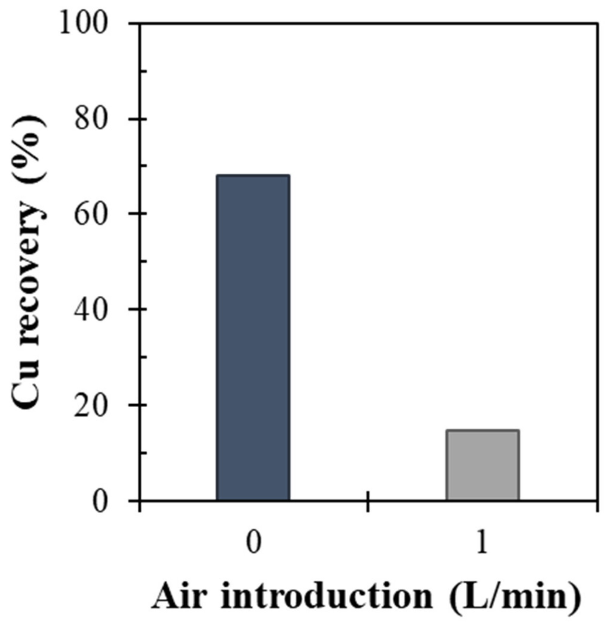
3.1. Flotation of Chalcopyrite
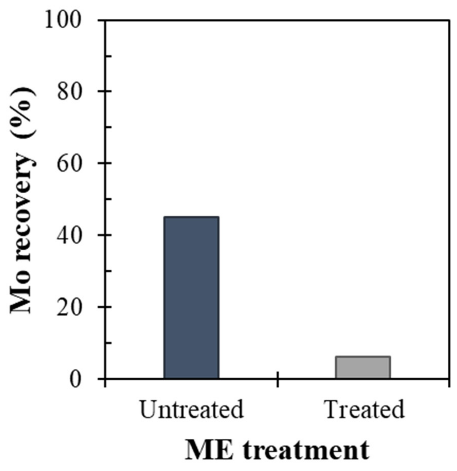
3.2. Flotation of Molybdenite
3.3. Flotation of Chalcopyrite/Molybdenite Mixture
4. Conclusions
- ME treatment using 10 mM had a negligible effect on the depression of chalcopyrite floatability, but air introduction during ME treatment dramatically reduced Cu recovery from ~70% to ~15%. The air introduction played an important role in enhancing ferrous oxidation occurring on the surface of chalcopyrite, thereby improving the formation of FePO4 coating on its surface.
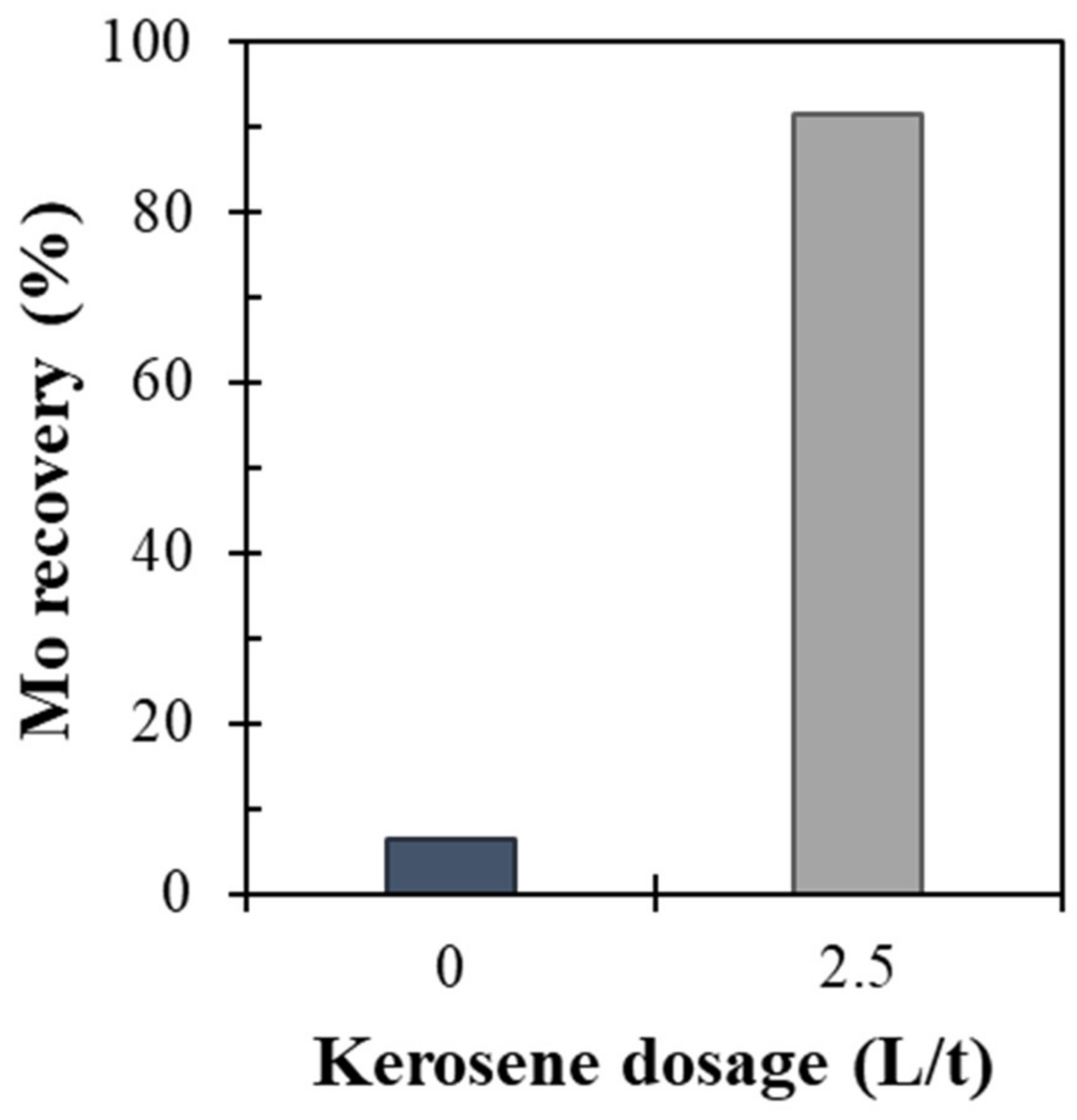
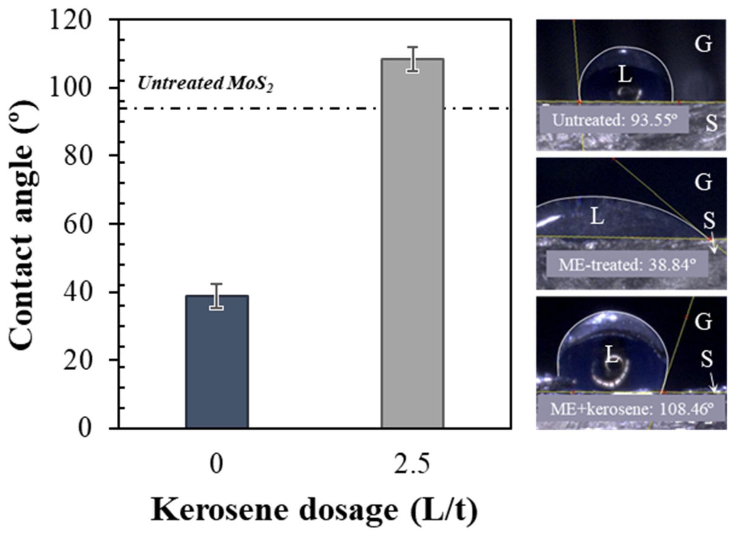
- Not only chalcopyrite, but the floatability of molybdenite was also depressed after ME treatment. The reduced floatability of ME-treated molybdenite, however, could be improved by utilizing emulsified kerosene during flotation.
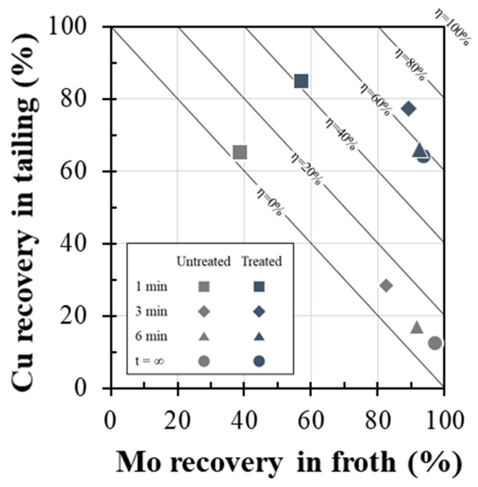
- The application of ME treatment was also effective for mixed minerals system that the separation efficiency increased from 10.9% (without ME treatment) to 66.8% (with ME treatment).
Author Contributions
Funding
Institutional Review Board Statement
Informed Consent Statement
Data Availability Statement
Conflicts of Interest
References
- Bulatovic, S.M. 12-Flotation of Copper Sulfide Ores. In Handbook of Flotation Reagents; Bulatovic, S.M., Ed.; Elsevier: Amsterdam, The Netherlands, 2007; pp. 235–293. ISBN 978-0-444-53029-5. [Google Scholar]
- Park, I.; Hong, S.; Jeon, S.; Ito, M.; Hiroyoshi, N. A Review of Recent Advances in Depression Techniques for Flotation Separation of Cu–Mo Sulfides in Porphyry Copper Deposits. Metals 2020, 10, 1269. [Google Scholar] [CrossRef]
- John, D.A.; Ayuso, R.A.; Barton, M.D.; Blakely, R.J.; Bodnar, R.J.; Dilles, J.H.; Gray, F.; Graybeal, F.T.; Mars, J.L.; McPhee, D.K.; et al. Porphyry Copper Deposit Model: Chapter B in Mineral Deposit Models for Resource Assessment; Scientific Investigations Report 2010-5070-B; U.S. Geological Survey: Menlo Park, CA, USA, 2010; 169p.
- Cioacă, M.-E.; Munteanu, M.; Lynch, E.P.; Arvanitidis, N.; Bergqvist, M.; Costin, G.; Ivanov, D.; Milu, V.; Arvidsson, R.; Iorga-Pavel, A.; et al. Mineralogical Setting of Precious Metals at the Assarel Porphyry Copper-Gold Deposit, Bulgaria, as Supporting Information for the Development of New Drill Core 3D XCT-XRF Scanning Technology. Minerals 2020, 10, 946. [Google Scholar] [CrossRef]
- Stull, D.R. Vapor Pressure of Pure Substances. Organic and Inorganic Compounds. Ind. Eng. Chem. 1947, 39, 517–540. [Google Scholar] [CrossRef]
- Amelunxen, P.; Schmitz, C.; Hill, H.; Goodweiler, N.; Andres, J. Molybdenum. In SME Mineral Processing & Extractive Metallurgy Handbook; Society for Mining, Metallurgy & Exploration (SME): Englewood, CO, USA, 2019; Volume 2, pp. 1891–1916. [Google Scholar]
- Hirajima, T.; Miki, H.; Suyantara, G.P.W.; Matsuoka, H.; Elmahdy, A.M.; Sasaki, K.; Imaizumi, Y.; Kuroiwa, S. Selective Flotation of Chalcopyrite and Molybdenite with H2O2 Oxidation. Miner. Eng. 2017, 100, 83–92. [Google Scholar] [CrossRef]
- Miki, H.; Matsuoka, H.; Hirajima, T.; Suyantara, G.P.W.; Sasaki, K. Electrolysis Oxidation of Chalcopyrite and Molybdenite for Selective Flotation. Mater. Trans. 2017, 58, 761–767. [Google Scholar] [CrossRef] [Green Version]
- Yin, Z.; Sun, W.; Hu, Y.; Zhang, C.; Guan, Q.; Zhang, C. Separation of Molybdenite from Chalcopyrite in the Presence of Novel Depressant 4-Amino-3-Thioxo-3,4-Dihydro-1,2,4-Triazin-5(2H)-One. Minerals 2017, 7, 146. [Google Scholar] [CrossRef] [Green Version]
- Park, I.; Tabelin, C.B.; Magaribuchi, K.; Seno, K.; Ito, M.; Hiroyoshi, N. Suppression of the Release of Arsenic from Arsenopyrite by Carrier-Microencapsulation Using Ti-Catechol Complex. J. Hazard. Mater. 2018, 344, 322–332. [Google Scholar] [CrossRef] [PubMed]
- Park, I.; Tabelin, C.B.; Seno, K.; Jeon, S.; Ito, M.; Hiroyoshi, N. Simultaneous Suppression of Acid Mine Drainage Formation and Arsenic Release by Carrier-Microencapsulation Using Aluminum-Catecholate Complexes. Chemosphere 2018, 205, 414–425. [Google Scholar] [CrossRef] [PubMed]
- Li, X.; Hiroyoshi, N.; Tabelin, C.B.; Naruwa, K.; Harada, C.; Ito, M. Suppressive Effects of Ferric-Catecholate Complexes on Pyrite Oxidation. Chemosphere 2019, 214, 70–78. [Google Scholar] [CrossRef] [PubMed]
- Park, I.; Tabelin, C.B.; Seno, K.; Jeon, S.; Inano, H.; Ito, M.; Hiroyoshi, N. Carrier-Microencapsulation of Arsenopyrite Using Al-Catecholate Complex: Nature of Oxidation Products, Effects on Anodic and Cathodic Reactions, and Coating Stability under Simulated Weathering Conditions. Heliyon 2020, 6, e03189. [Google Scholar] [CrossRef] [PubMed] [Green Version]
- Park, I.; Higuchi, K.; Tabelin, C.B.; Jeon, S.; Ito, M.; Hiroyoshi, N. Suppression of Arsenopyrite Oxidation by Microencapsulation Using Ferric-Catecholate Complexes and Phosphate. Chemosphere 2021, 269, 129413. [Google Scholar] [CrossRef] [PubMed]
- Park, I.; Hong, S.; Jeon, S.; Ito, M.; Hiroyoshi, N. Flotation Separation of Chalcopyrite and Molybdenite Assisted by Microencapsulation Using Ferrous and Phosphate Ions: Part I. Selective Coating Formation. Metals 2020, 10, 1667. [Google Scholar] [CrossRef]
- Hornn, V.; Ito, M.; Shimada, H.; Tabelin, C.B.; Jeon, S.; Park, I.; Hiroyoshi, N. Agglomeration-Flotation of Finely Ground Chalcopyrite and Quartz: Effects of Agitation Strength during Agglomeration Using Emulsified Oil on Chalcopyrite. Minerals 2020, 10, 380. [Google Scholar] [CrossRef]
- Hornn, V.; Ito, M.; Shimada, H.; Tabelin, C.B.; Jeon, S.; Park, I.; Hiroyoshi, N. Agglomeration–Flotation of Finely Ground Chalcopyrite Using Emulsified Oil Stabilized by Emulsifiers: Implications for Porphyry Copper Ore Flotation. Metals 2020, 10, 912. [Google Scholar] [CrossRef]
- Castro, S. Challenges in flotation of Cu–Co sulfide ores in sea water. In The First International Symposium on Water in Mineral Processing; Society for Mining, Metallurgy & Exploration (SME): Littleton, CO, USA, 2012; pp. 29–40. [Google Scholar]
- Jeldres, R.I.; Arancibia-Bravo, M.P.; Reyes, A.; Aguirre, C.E.; Cortes, L.; Cisternas, L.A. The Impact of Seawater with Calcium and Magnesium Removal for the Flotation of Copper-Molybdenum Sulphide Ores. Miner. Eng. 2017, 109, 10–13. [Google Scholar] [CrossRef]
- Hirajima, T.; Suyantara, G.P.W.; Ichikawa, O.; Elmahdy, A.M.; Miki, H.; Sasaki, K. Effect of Mg2+ and Ca2+ as Divalent Seawater Cations on the Floatability of Molybdenite and Chalcopyrite. Miner. Eng. 2016, 96–97, 83–93. [Google Scholar] [CrossRef]
- Suyantara, G.P.W.; Hirajima, T.; Miki, H.; Sasaki, K. Floatability of Molybdenite and Chalcopyrite in Artificial Seawater. Miner. Eng. 2018, 115, 117–130. [Google Scholar] [CrossRef]
- Hirajima, T.; Mori, M.; Ichikawa, O.; Sasaki, K.; Miki, H.; Farahat, M.; Sawada, M. Selective Flotation of Chalcopyrite and Molybdenite with Plasma Pre-Treatment. Miner. Eng. 2014, 66–68, 102–111. [Google Scholar] [CrossRef]
- King, R.P. Flotation. In Modeling and Simulation of Mineral Processing Systems; Butterworth Heinemann: Oxford, UK, 2001; pp. 289–350. [Google Scholar]
- Xu, M. Modified Flotation Rate Constant and Selectivity Index. Miner. Eng. 1998, 11, 271–278. [Google Scholar] [CrossRef]
- Bilal, M.; Ito, M.; Koike, K.; Hornn, V.; Ul Hassan, F.; Jeon, S.; Park, I.; Hiroyoshi, N. Effects of Coarse Chalcopyrite on Flotation Behavior of Fine Chalcopyrite. Miner. Eng. 2021, 163, 106776. [Google Scholar] [CrossRef]
- Farahat, M.; Hirajima, T.; Sasaki, K.; Doi, K. Adhesion of Escherichia Coli onto Quartz, Hematite and Corundum: Extended DLVO Theory and Flotation Behavior. Colloids Surf. B Biointerfaces 2009, 74, 140–149. [Google Scholar] [CrossRef] [PubMed]
- Aikawa, K.; Ito, M.; Kusano, A.; Park, I.; Oki, T.; Takahashi, T.; Furuya, H.; Hiroyoshi, N. Flotation of Seafloor Massive Sulfide Ores: Combination of Surface Cleaning and Deactivation of Lead-Activated Sphalerite to Improve the Separation Efficiency of Chalcopyrite and Sphalerite. Metals 2021, 11, 253. [Google Scholar] [CrossRef]


| Parameters | Untreated | Treated | ||
|---|---|---|---|---|
| Chalcopyrite | Molybdenite | Chalcopyrite | Molybdenite | |
| R2 | 0.99 | 0.99 | 0.93 | 0.99 |
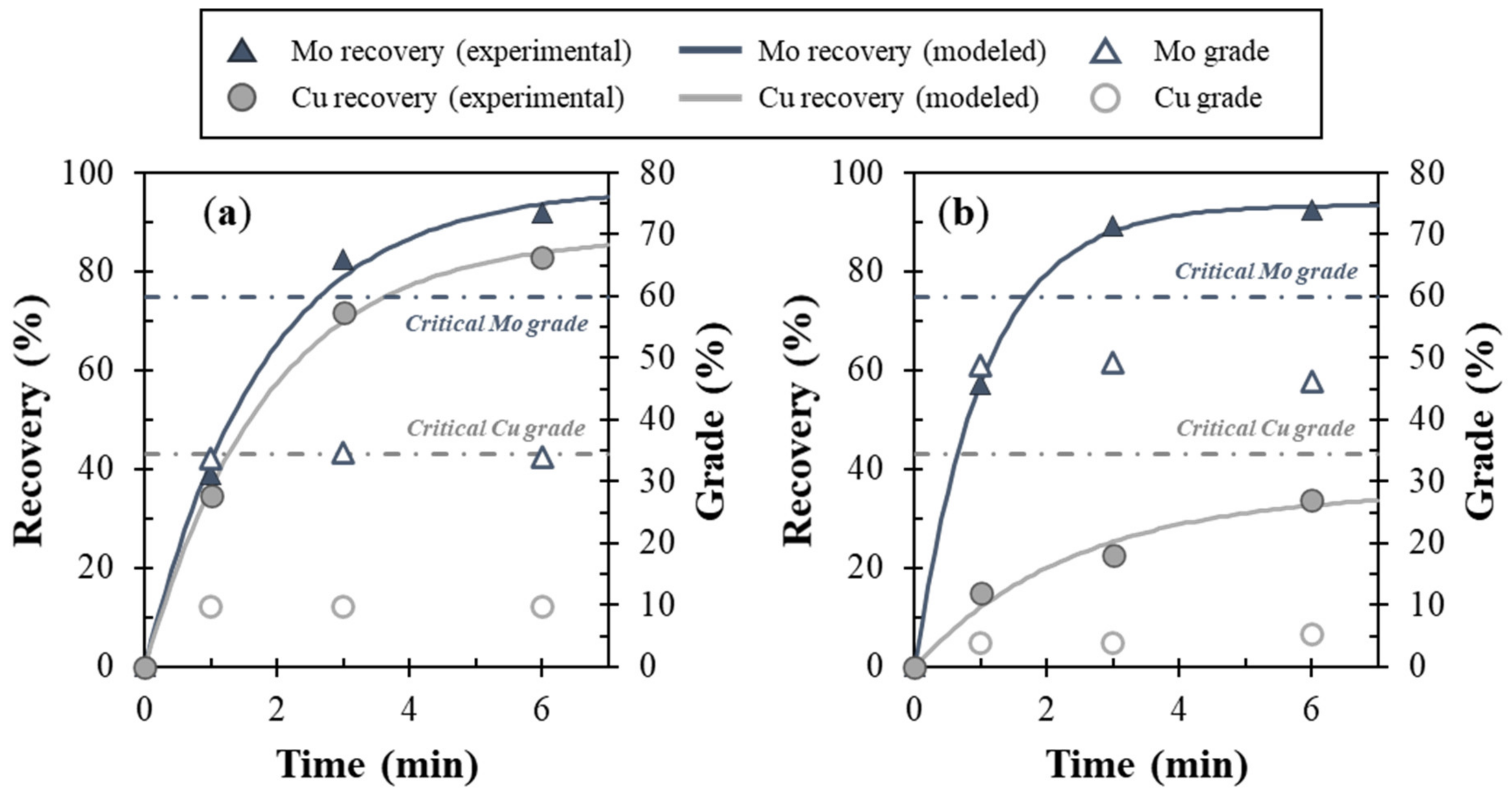
| R∞ (%) | 87.3 | 97.0 | 35.7 | 93.5 |
| k (min−1) | 0.54 | 0.56 | 0.41 | 0.96 |
| KM (min−1) | 0.47 | 0.54 | 0.15 | 0.89 |
| S.I. (Mo/Cu) | 1.16 | 6.08 | ||
Publisher’s Note: MDPI stays neutral with regard to jurisdictional claims in published maps and institutional affiliations. |
© 2021 by the authors. Licensee MDPI, Basel, Switzerland. This article is an open access article distributed under the terms and conditions of the Creative Commons Attribution (CC BY) license (http://creativecommons.org/licenses/by/4.0/).
Share and Cite
Park, I.; Hong, S.; Jeon, S.; Ito, M.; Hiroyoshi, N. Flotation Separation of Chalcopyrite and Molybdenite Assisted by Microencapsulation Using Ferrous and Phosphate Ions: Part II. Flotation. Metals 2021, 11, 439. https://0-doi-org.brum.beds.ac.uk/10.3390/met11030439
Park I, Hong S, Jeon S, Ito M, Hiroyoshi N. Flotation Separation of Chalcopyrite and Molybdenite Assisted by Microencapsulation Using Ferrous and Phosphate Ions: Part II. Flotation. Metals. 2021; 11(3):439. https://0-doi-org.brum.beds.ac.uk/10.3390/met11030439
Chicago/Turabian StylePark, Ilhwan, Seunggwan Hong, Sanghee Jeon, Mayumi Ito, and Naoki Hiroyoshi. 2021. "Flotation Separation of Chalcopyrite and Molybdenite Assisted by Microencapsulation Using Ferrous and Phosphate Ions: Part II. Flotation" Metals 11, no. 3: 439. https://0-doi-org.brum.beds.ac.uk/10.3390/met11030439