Article

Effect of Filler Metal Type on Microstructure and Mechanical Properties of Fabricated NiAl Bronze Alloy Using Wire Arc Additive Manufacturing System

Advanced Forming Process R&D Group, Korea Institute of Industrial Technology, Ulsan 44776, Korea
*
Author to whom correspondence should be addressed.
Submission received: 5 February 2021 / Revised: 23 February 2021 / Accepted: 10 March 2021 / Published: 19 March 2021
(This article belongs to the Special Issue Additive Manufacturing of Non-ferrous Alloys)

Abstract

:
This study observed the effect of filler metal type on mechanical properties of NAB (NiAl-bronze) material fabricated using wire arc additive manufacturing (WAAM) technology. The selection of filler metal type is must consider the field condition, mechanical properties required by customers, and economics. This study analyzed the bead shape for representative two kind of filler metal types use to maintenance and fabricated a two-dimensional bulk NAB material. The cold metal transfer (CMT) mode of gas metal arc welding (GMAW) was used. For a comparison of mechanical properties, the study obtained three specimens per welding direction from the fabricated bulk NAB material. In the tensile test, the NAB material deposited using filler metal wire A showed higher tensile strength and lower elongation (approx. +71 MPa yield strength, +107.1 MPa ultimate tensile strength, −12.4% elongation) than that deposited with filler metal wire B. The reason is that, a mixture of tangled fine α platelets and dense lamellar eutectoid α + κIII structure with β′ phases was observed in the wall made with filler metal wire A. On the other hand, the wall made with filler metal wire B was dominated by coarse α phases and lamellar eutectoid α + κIII structure in between.

Graphical Abstract

1. Introduction

Nickel aluminum bronze (NAB) alloys are commonly used in shipbuilding and marine engineering parts due to their excellent corrosion resistance and mechanical properties [1]. NAB alloys are copper-based quaternary alloys that generally contain aluminum, nickel, and iron (8–12 wt. % aluminum, 3–6 wt. % nickel, and iron) [2].
NAB alloy has a two-phase microstructure an equilibrium fcc α phase and a high-temperature bcc β phase. NAB alloys increase mechanical properties because when nickel and iron are added to the copper-aluminum alloy, several intermetallic κ phases are precipitated between α and β phases [3]. In addition, the low manganese content (max. 3.5 wt. %) of commercial NAB alloys has the advantage of improving the casting ability and stabilizing the microstructure [4,5]. NAB alloys are mainly used for marine propellers, pumps, and valves of huge ships and marine plants due to superior corrosion resistance and mechanical properties compared to general Cu-based alloys [6,7,8,9].
The 3D printing process refers to additive manufacturing (AM), in which 3D objects are manufactured by depositing materials based on 3D computer-aided design (CAD) information [10,11]. The first-generation 3D printing equipment is a commercial 3D system rapid prototyping machine, it is developed in the late 80 s, and various 3D printing machines such as powder bed fusion (PBF) processes and binder jetting (BJ) method have been developed since the 90 s [12]. One of the AM processes, direct energy deposition (DED) is deposited by melting a powder or solid filler metal using a heat source such as an electron beam, arc, or plasma [13]. Recently, CO2 lasers, Nd:YAG lasers, Yb-fiber lasers, and excimer lasers are extensively used as 3D printing sources due to which bring great benefits, such as energy-saving, less material consumption, and efficient production [14,15]. Wire-arc additive manufacturing (WAAM) is one of DED process that uses the conventional gas metal arc welding (GMAW) process as a heat source to deposit solid metal filler wires [16].
WAAM has the advantages that handling of commercial filler metal because commercial arc welding equipment can be used [17]. In the GMAW processes, there are no limitations on the size of parts that can be manufactured because there is no need to work inside the chamber due to the shielding gas provided by the welding gun. It also has a faster deposition rate, larger bead size, and higher modifiability compared to the powder process [18,19]. In addition, it is possible to minimize material loss by depositing weld bead according to the part design, and because the manufacturing speed is faster compared to the existing mold-making process, the processing time can be shortened [20,21]. For this reason, additive manufacturing (AM) has a competitive advantage to replace traditional processes in even strict industries such as aeronautical and automotive [22].
Recently, the application of WAAM has been expanded to fabricate propellers using bronze alloys, brass alloys, etc. Dong et al. [23] evaluated the microstructure and mechanical properties of additive-manufactured NAB alloys and cast NABs and then confirmed that functional NAB alloys could be manufactured through WAAM. Jisun Kim et al. [24] compared the shape of a single bead according to welding conditions through WAAM and compared and analyzed the mechanical properties (tensile, yield, elongation, hardness, impact, wear) of the cast NAB alloy and the deposited NAB alloy. However, to expand the applicability of the NAB alloy to the WAAM process, it is necessary to analyze the NAB material made with WAAM. In general, when using GMAW to manufacture a product with WAAM, the quality of the product is determined by the GMAW parameters, and the typical parameters are welding current, welding speed, welding voltage, filler metal type, and shielding gas [25].
In particular, in the case of the WAAM process, appropriately selection should be done according to the application, mechanical properties required by customers, and economics, because of filler metal are vary. The main role of the filler metal is joining the materials but greatly affects the WAAM product mechanical properties and quality due to each filler metal has different properties (wire type, chemical composition, strength, and diameter), which affect the output results from the welding Thus, care should be taken when selecting the filler metal for the WAAM process. In this study, compares the mechanical and metallurgical properties of two-dimensional NAB walls deposited using different commercial filler metals. First of all, deposited wall condition and inner defect for two kinds of filler metal with visual inspection and X-ray are analyzed. In addition, mechanical properties according to filler wire type was performed with direction of test piece production. The microstructure and fracture morphology analysis are performed to discuss in depth with supporting evidence differences in mechanical results.

2. Materials and Methods

In this study, the substrate is C95800, with dimensions of 150 mm (D) × 250 mm (H) × 15 mm (T), as defined in ASTM B 505. For the deposition experiment, two kinds of filler metal were used to prepare the deposits: ERCuNiAl (wire A) and CuAl9Ni5Fe3Mn2 (wire B). The chemical composition of materials and filler metals is shown in Table 1. A cold metal transfer (CMT) welding machine (TPS 4000, Fronius, Australia) and the robot motion system (KR60HA, Kuka, Germany) were used with a synergic number of 1712 (CuAl8-CMT mode). Figure 1 shows the configuration of the robot system and the GMAW machine used in the experiment. In a CMT welding machine, the synergic number should be selected according to material type, filler metal diameter and type, and the ratio of shielding gas and be selected welding conditions by welding wire feed rate. WAAM’s process using GMAW has the same input parameters as the general GMAW welding process, but it requires additional interlayer distance for bead deposition and a path to implement the part shape [26].
Figure 2 shows the schematic diagram of the WAAM process using GMAW. A zig-zag travel direction was used to prevent bead droop at the start and end positions. As shown in Table 2, this experiment used a contact tip to work distance (CTWD) of 15 mm, 100% Ar shielding gas with a flow rate of 20 L/min, and a torch angle of 90°. The wire feeding rate was 7.8 m/min, and the travel speed was 0.2 m/min. In CMT welding, the magnitude of the current and voltage are determined according to the feeding rate of the filler metal. Because the deposited NAB alloy is anisotropic, its tensile strength was tested in two directions (welding direction, WD, and transverse direction, TD) and two angles on samples from each of the two filler metals. Figure 3 shows the specimen preparation procedures for the tensile test. The tensile specimen was collected by laser cutting. To analysis the microstructure for NAB alloy, a mixed solution of 100 mL HNO3 + 100 mL alcohol was selected as the etching agent. The microstructure of the specimens was analyzed using an optical microscope (OM) and scanning electron microscopy (SEM). Tensile tests for three specimens were performed at room temperature at each condition, with cross head speed of 10 mm/min.

3. Results and Discussion

3.1. Deposited Material

Figure 4 shows a 100 mm long and 100 mm high wall deposited with various types of filler metal. Since the molten metal is solidified during the deposition process, strong dendrites are formed around small nuclei, causing metal anisotropy, which is determined by the deposition direction [27,28]. Wei [29] reported that in the deposition process using arc welding, the dendrites were determined by the deposition direction, and the bead shape and the surface condition of the beads were similar after deposition. The deposited walls were made uniformly, but there were lateral collapses at the start and endpoints of some layers of both walls. Typically, this is due to excessive heat sinks, heat input, cooling rates, or molten metal in the weld pool [30,31]. It can also be caused by errors such as mis teaching, manual teaching, and arc end delay time. The reason why the bead collapsed at the start and endpoints in this study is due to the lack of consistency of the welding start position by manual welding. However, from the perspective of the WAAM process, the collapsed bead is cut by processing to make the final product, so it is not important in terms of product precision. In general, evaporated wall parts have defects such as internal voids due to rapid solidification and shrinkage, which should be noted because mechanical properties such as tensile strength, fatigue performance and impact resistance are affected [32].
Figure 5 shows the X-ray 3D CT analysis of deposited NAB components. Defects in the deposited wall components, such as internal voids or cracks, were not observed. Other typical defects, such as portions of un-melted wire stuck to WAAM component walls, or large distortions due to heat accumulation, also were not observed [33].

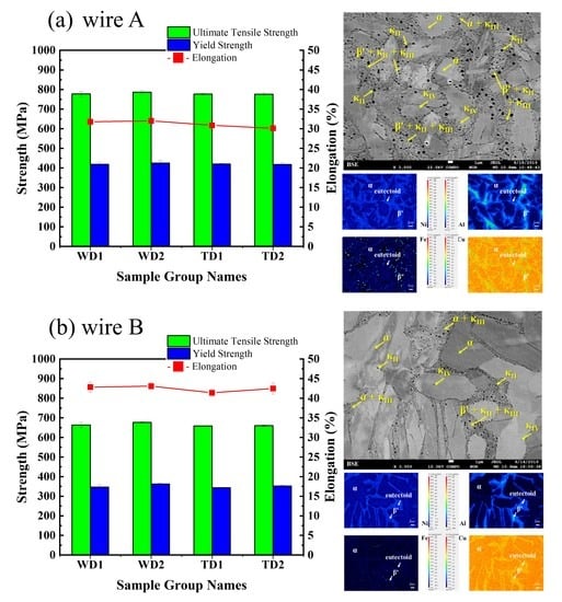
3.2. Mechanical Properties

The visual inspections and X-ray results confirmed that the dimensions of the deposited walls were similar for both types of filler metal wire. To compare the mechanical properties of the deposited walls according to filler metal type, a tensile test was conducted. Figure 6 shows the strength testing results. Because the deposited NAB material is anisotropic, the strength test of the deposited NAB materials was performed in two directions and two angles on each of the two filler metals. These two directions are divided into type WD and type TD, samples from both wire types had better mechanical properties than the initial cast material (590 MPa). No direction-dependent effects were observed. However, the strength and elongation differed depending on filler metal type. For the deposited NAB components using wire A, the average tensile strength was 777.6 MPa ± 12.5 MPa, the average yield strength was 418.9 MPa ± 10.6 MPa, and the average elongation was 30%, regardless of the direction and angle.
The deposited NAB components using wire B showed an average tensile strength of 663.9 MPa ± 12.9 MPa, an average yield strength of 347.06 MPa ± 11.7 MPa, and an aver-age elongation of 42.4%. In this test, the wall deposited using wire A had greater mechanical strength, and less elongation, than that of the wall deposited using wire B. The result that the mechanical properties of the deposited NAB vary depending on the type of filler metal is a very important factor in the actual structural design. In other words, it is very important to set the filler metal that meets the required conditions when designing the actual structure.

3.3. Microstructure of Deposited NAB Wall Components

Microstructures were analyzed to determine reasons for changes in mechanical properties such as strength and elongation. Figure 7 is a macro photo of a cross-section showing a high-density NAB alloy wall deposited with wire A. Figure 7a shows an overall image of the deposited wall. I confirmed that it was formed quite evenly. Figure 7b shows a representative microstructure of the deposited area. The deposited walls are organized in the following order: weld zone (WZ)—CGHAZ (coarse heat affected zone)—FGHAZ (fine heat affected zone)—ICHAZ (inter critical heat affected zone) formed by reheating—weld zone. Mainly widmanstätten α and very fine martensite (dark areas) were observed.
Figure 7c shows the heat affected zone (HAZ) and WZ zone found in the first layer bordering the substrate (cast NAB). The microstructure has undergone significant changes in HAZ. In particular, conversion of the eutectic structure to martensite took place in the region close to the line of fusion between WZ and HAZ. The peak temperature in this region is higher than the eutectic point and a β structure is formed. This was maintained by rapid cooling and subsequent formation of martensitic structures. The temperature gradient with distance from the fusion line led to the region of the partially deformed eutectic structure. These martensitic structures (β′) are harder than α phase, but are fragile and susceptible to corrosion and cavitation erosion, which is undesirable [34].
Figure 8 shows the microstructure and EPMA results for the deposited walls made with wire A. A mixture of tangled fine α platelets and dense lamellar eutectoid α + κIII structure with β′ phases was observed in Figure 8a. The lamellar eutectoid α + κIII structure formed with serrated boundaries near α platelets. Additionally, the β′ phases were found at the grain boundaries of α phases, consistent with the EPMA results. Furthermore, a larger amount of κIV precipitates were observed than in wire B. These structural features would have resulted in a fine α grain size and increment of strength [35]. Additionally, a larger amount of κII precipitates were observed than in wire B, which could reduce the ductility of the product. The increase in tensile and yield strength in the product made with Wire A can be attributed to the finer and more homogeneous solidification structure (grain boundary strengthening) and the presence of numerous fine κIV precipitates. These microstructural features can be attributed to the large amount of alloying elements in wire A; it had a greater chance of forming β phases, which transformed into β′ + κ precipitates during the subsequent cooling, rather than dissolving into α phase. The lamellar eutectoid intermetallic κ phase formed as penetrations into α platelets.
It would function as quasi-grain boundaries. Additionally, it could have resulted in fine α grain size and increment of strength. Figure 8b shows the microstructural features and EPMA results for the deposited wall made with wire B, dominated by the coarse α phases interspersed with lamellar eutectoid α + κIII structure. Varied sizes of κII and κIV were precipitated at the grain boundaries and within the grains, respectively. A small amount of retained β was found at the border of the grain boundary of α platelets and κ intermetallics. A small amount of κII precipitates were observed, which decreases the ductility. The microstructural analysis and EPMA indicate that the filler metal type affects the size of α phase and the fraction of the β′and κ precipitates. These differences affect the tensile and yield strength values.

3.4. Fracture Morphology Analysis of Deposited NAB Wall Components

The fracture surface of the transverse tensile test is shown in Figure 9. In both cases, it was observed that brittle fracture and micro void adhesion were mixed with elongation of 20% or more in both the fractured surface. The deposited walls mainly contain widmanstätten α. The fracture surface exhibits the lath structure, and it was observed that the fracture propagates preferentially along the lath boundary. The fine dimples on the fracture surface match the microstructure. In the case of the sedimentary wall made of wire A (Figure 9a), a complex structure dominated by α and β′phases with randomly scattered κ precipitates was observed, as can be seen from the microstructure analysis results. An intricately tangled fracture surface is shown in the enlarged image. A fracture face of the deposited wall made with wire B (Figure 9b) has a comparatively simple α and α + κIII eutectoid structure with κII and κIV, consistent with the microstructural analysis results. The fracture surfaces were found to function as an intergranular fracture mode of the dominant structures. We observed the grain boundaries of α and the location of the κ precipitates initially existed. The results indicate that the different filler metal types are associated with microstructural differences, such as the size of α phase and the fraction of the β′and κ precipitates, which appear to affect the fracture surface.

4. Conclusions

In this study, the mechanical and metallurgical properties of deposited NAB components using WAAM (wire arc additive manufacturing) were identified according to the wire type, and the conclusions in this research are as follows:
  • A high-density NAB alloy product without defects was produced by the WAAM process using commercial filler metal. Through visual inspection and X-ray analysis, it was confirmed that there was no visual difference according to the wire type.
  • The variations in mechanical properties between the wall’s components deposited with different filler metals type were significant. The deposited components made with filler metal wire A exhibited higher tensile and yield strength, but less elongation (approx. +71 MPa yield strength, +107.1 MPa ultimate tensile strength, −12.4% elongation).
  • Through microstructural analysis and EPMA results identified differences in the size of α phase and the fraction of the β′and κ precipitates depending on the filler metal type. The as-fabricated wall made with filler metal wire A exhibited considerably finer microstructure as compared to that made with filler metal wire B. For this reason, it was judged that the tensile strength made of wire A was superior to that of wire B.
  • It was considered through this study that it is necessary to select a filler metal wire that meets the requirements for product manufacturing.

Author Contributions

Conceptualization, J.K. (Jaewon Kim), J.K. (Jaedeuk Kim), J.C. and C.J.; experiment, J.K.(Jaedeuk Kim) and J.C.; validation, J.K.(Jaewon Kim), J.K.(Jaedeuk Kim), J.C. and C.J.; paper research, J.K.(Jaewon Kim), J.K.(Jaedeuk Kim), J.C. and C.J.; data analysis, J.K.(Jaewon Kim), J.K.(Jaedeuk Kim), J.C. and C.J.; writing—original draft preparation, J.K.(Jaewon Kim); writing—review and editing, J.K.(Jaewon Kim), J.K.(Jaedeuk Kim), J.C. and C.J.; supervision, C.J.; project administration, C.J. All authors have read and agreed to the published version of the manuscript.

Funding

This research has been conducted with the support of the Ministry of Trade, Industry and Energy (MOTIE) as “Development of manufacture/equipment/manufacturing process of 2m grade bronze alloy propeller for ship using Wire Arc 3D printing (20002805).”

Institutional Review Board Statement

Not applicable.

Informed Consent Statement

Not applicable.

Data Availability Statement

Not applicable.

Conflicts of Interest

The authors declare no conflict of interest.

Nomenclature

NABNickel-Aluminum Bronze
WAAMWire Arc Additive Manufacturing
GMAWGas Metal Arc Welding
CMTCold Metal Transfer
DEDDirect Energy Deposition
CADComputer-aided Design
CTWDContact Tip to Work Distance
WDWelding Direction
TDTransverse Direction
OMOptical Microscopy
SEMScanning Electron Microscopy

References

  1. Dharmendra, C.; Hadadzadeh, A.; Amirkhiz, B.S.; Mohammadi, M. The Morphology, Crystallography, and Chemistry of Phases in Wire-Arc Additively Manufactured Nickel Aluminum Bronze. In TMS 2019 148th Annual Meeting & Exhibition Supplemental Proceedings; Springer: Cham, Switzerland, 2019; pp. 443–453. [Google Scholar] [CrossRef]
  2. Brezina, P. Heat treatment of complex aluminium bronzes. Int. Mater. Rev. 1982, 27, 77–120. [Google Scholar] [CrossRef]
  3. Cook, M.; Fentiman, W.P.; Davis, E. Observations on the structure and properties of wrought copper-aluminium-nickel-iron alloys. J. Inst. Met. 1952, 80, 419–429. [Google Scholar]
  4. Strang, J.R.C. Cast valve materials for seawater service nickel-aluminum bronze and its rivals. In Proceedings of the Valve World Conference at the Maastricht Exhibition and Congress Center, Maastricht, The Netherlands, 7–9 November 2006. [Google Scholar]
  5. Powell, C.; Stillman, H. Corrosion Behavior of Copper Alloys Used in Marine Aquaculture; International Copper Association, Ltd.: New York, NY, USA, 2009; pp. 1–3. [Google Scholar]
  6. Culpan, E.; Rose, G. Microstructural characterization of cast nickel aluminium bronze. J. Mater. Sci. 1978, 13, 1647–1657. [Google Scholar] [CrossRef]
  7. Wu, Z.; Cheng, Y.F.; Liu, L.; Lv, W.; Hu, W. Effect of heat treatment on microstructure evolution and erosion–corrosion behavior of a nickel–aluminum bronze alloy in chloride solution. Corros. Sci. 2015, 98, 260–270. [Google Scholar] [CrossRef]
  8. Callcut, V.A. Aluminium bronze for industrial use. Met. Mater. 1989, 53, 128–132. [Google Scholar]
  9. Dharmendra, C.; Hadadzadeh, A.; Amirkhiz, B.; Ram, G.J.; Mohammadi, M. Microstructural evolution and mechanical behavior of nickel aluminum bronze Cu-9Al-4Fe-4Ni-1Mn fabricated through wire-arc additive manufacturing. Addit. Manuf. 2019, 30, 100872. [Google Scholar] [CrossRef]
  10. Shahrubudin, N.; Lee, T.; Ramlan, R. An Overview on 3D Printing Technology: Technological, Materials, and Applications. Proc. Manuf. 2019, 35, 1286–1296. [Google Scholar] [CrossRef]
  11. Nichols, M.R. How does the automotive industry benefit from 3D metal printing? Met. Powder Rep. 2019, 74, 257–258. [Google Scholar] [CrossRef]
  12. Murr, L.E.; Gaytan, S.M.; Ramirez, D.A.; Martinez, E.; Hernandez, J.; Amato, K.N.; Shindo, P.W.; Medina, F.R.; Wicker, R.B. Metal Fabrication by Additive Manufacturing Using Laser and Electron Beam Melting Technologies. J. Mater. Sci. Technol. 2012, 28, 1–14. [Google Scholar] [CrossRef]
  13. Kim, S.; Lim, S.; Chun, C.-K. Repair Properties of Desulfurization Pump Part Layers by Direct Energy Deposited Additive Manufacturing Process. J. Weld. Join. Soc. 2020, 38, 92–97. [Google Scholar] [CrossRef] [Green Version]
  14. Wang, C.; Suder, W.; Ding, J.; Williams, S. Wire based plasma arc and laser hybrid additive manufacture of Ti-6Al-4V. J. Mater. Process. Technol. 2021, 293, 117080. [Google Scholar] [CrossRef]
  15. Lee, H.; Lim, C.H.J.; Low, M.J.; Tham, N.; Murukeshan, V.M.; Kim, Y.J. Lasers in additive manufacturing: A review. Int. J. Precis. Eng. Manuf. Green Tech. 2017, 4, 307–322. [Google Scholar] [CrossRef]
  16. Byun, J.-G.; Cho, S.M. Trend of Metal 3D Printing by Welding. J. Weld. Join. Soc. 2016, 34, 1–8. [Google Scholar] [CrossRef] [Green Version]
  17. Wharton, J.A.; Barik, R.; Kear, G.; Wood, R.J.K.; Stokes, K.; Walsh, F. The corrosion of nickel–aluminium bronze in seawater. Corros. Sci. 2005, 47, 3336–3367. [Google Scholar] [CrossRef]
  18. Hwa, L.C.; Rajoo, S.; Noor, A.M.; Ahmad, N.; Uday, M. Recent advances in 3D printing of porous ceramics: A review. Curr. Opin. Solid State Mater. Sci. 2017, 21, 323–347. [Google Scholar] [CrossRef]
  19. Kam, D.-H.; Kim, Y.-M.; Kim, C. Recent Studies of Laser Metal 3D Deposition with Wire Feeding. J. Weld. Join. Soc. 2016, 34, 35–40. [Google Scholar] [CrossRef] [Green Version]
  20. Karakurt, I.; Lin, L. 3D printing technologies: Techniques, materials, and post-processing. Curr. Opin. Chem. Eng. 2020, 28, 134–143. [Google Scholar] [CrossRef]
  21. Cunningham, C.; Flynn, J.; Shokrani, A.; Dhokia, V.; Newman, S. Invited review article: Strategies and processes for high quality wire arc additive manufacturing. Addit. Manuf. 2018, 22, 672–686. [Google Scholar] [CrossRef]
  22. Haizea, G.B.; Amaia, C.-O.; Lamikiz, A.; Lopez de Lacalle, L.N. Manufacturing Processes of Integral Blade Rotors for Turbomachinery, Processes and New Approaches. Appl. Sci. 2020, 10, 3063. [Google Scholar] [CrossRef]
  23. Ding, D.; Pan, Z.; Van Duin, S.; Li, H.; Shen, C. Fabricating Superior NiAl Bronze Components through Wire Arc Additive Manufacturing. Materials 2016, 9, 652. [Google Scholar] [CrossRef] [Green Version]
  24. Kim, J.; Kim, J.; Pyo, C. Comparison of Mechanical Properties of Ni-Al-Bronze Alloy Fabricated through Wire Arc Additive Manufacturing with Ni-Al-Bronze Alloy Fabricated through Casting. Metals 2020, 10, 1164. [Google Scholar] [CrossRef]
  25. Wahsh, L.M.; Elshater, A.E.; Mansour, A.K.; Hamdy, F.A.; Turky, M.A.; Azzam, M.O.; Salem, H.G. Parameter selection for wire arc additive manufacturing (WAAM) process. In Proceedings of the Materials Science and Technology 2018, Columbus, OH, USA, 14–18 October 2018; pp. 78–85. [Google Scholar] [CrossRef]
  26. Kozamernik, N.; Bracun, D.; Klobcar, D. WAAM system with interpass temperature control and forced cooling for near-net-shaper printing of small metal components. Int. J. Adv. Manuf. Technol. 2020, 110, 1955–1968. [Google Scholar] [CrossRef]
  27. Li, Y.; Li, S.; Yang, L.; Zhong, H. Microstructure and properties of twinned dendrites in directionally solidified A356 alloy. Mater. Sci. Eng. A. 2018, 734, 7–19. [Google Scholar] [CrossRef]
  28. Wang, L.; Wei, Y.; Zhan, X.; Yu, F.; Cao, X.; Gu, C.; Ou, W. Simulation of dendrite growth in the laser welding pool of aluminum alloy 2024 under transient conditions. J. Mater. Process. Technol. 2017, 246, 22–29. [Google Scholar] [CrossRef]
  29. Wei, H.L.; Mazumder, J.; Debroy, T. Evolution of solidification texture during additive manufacturing. Sci. Rep. 2015, 5, 16446. [Google Scholar] [CrossRef] [PubMed] [Green Version]
  30. Kim, J.-D.; Kim, J.W.; Cheon, J.Y.; Kim, Y.-D.; Ji, C. Effect of shielding gases on the wire arc additive manufacturability of 5 Cr-4 Mo tool steel for die casting mold making. Korean J. Met. Mater. 2020, 5812, 852–862. [Google Scholar] [CrossRef]
  31. Luo, Y.; Li, J.; Xu, J.; Zhu, L.; Han, J.; Zhang, C. Influence of pulsed arc on the metal droplet deposited by projected transfer mode in wire-arc additive manufacturing. Mater. Process. Tech. 2018, 259, 353–360. [Google Scholar] [CrossRef]
  32. Campbell, F.C. Inspection of Metals: Understanding the Basics; ASM International: Russell Township, OH, USA, 2013; pp. 411–417. [Google Scholar]
  33. Rodrigues, T.; Duarte, V.; Miranda, R.M.; Santos, T.G.; Oliveira, J.P. Current status and perspectives on wire and arc additive manufacturing (WAAM). Materials 2019, 12, 1121. [Google Scholar] [CrossRef] [Green Version]
  34. Yu, H.; Zheng, Y.; Yao, Z. Cavitation erosion corrosion behaviour of manganese-nickel-aluminum bronze in comparison with manganese-brass. J. Mater. Sci. Technol. 2009, 25, 758–766. [Google Scholar]
  35. Manikandan, R.; Kumaresh Babu, S.P.; Murali, M.; Vallimanalan, A. Investigation of microstructure and mechanical properties in Nickel aluminium Bronze alloy with Nb and Y for aqueous applications. Mater. Today Proc. 2020, 27, 2591–2595. [Google Scholar] [CrossRef]
Figure 1. Wire arc additive manufacturing (WAAM) system adopted in the experiment.
Metals 11 00513 g001
Figure 2. Schematic illustration of experimental variable.
Metals 11 00513 g002
Figure 3. Schematic illustration of tensile strength test specimen location; (a) welding direction (x-y axis), (b) transverse direction (x-z axis).
Metals 11 00513 g003
Figure 4. Additively-manufactured NAB components and 3D X-ray analysis; (a) isometric view (b) top view (c) side view.
Metals 11 00513 g004
Figure 5. 3D X-ray of additively-manufactured NAB components (a) wire A; (b) wire B.
Metals 11 00513 g005
Figure 6. Comparison of tensile properties in the WAAM-fabricated NAB (a) wire A; (b) wire B.
Metals 11 00513 g006
Figure 7. Microstructure morphology in cross-section (y-z plane) of as-fabricated components; (a) whole profile of the part in cross-section (y-z plane) (b) the middle region; (c) the bottom region.
Metals 11 00513 g007
Figure 8. Phase analysis of intermetallic phase and EPMA results on additively-manufactured NAB components made in (a) wire A; (b) wire B.
Metals 11 00513 g008
Figure 9. Fracture morphology of the tensile sample and EDS analysis results of (a) wire A; (b) wire B.
Metals 11 00513 g009
Table 1. Chemical compositions and mechanical properties of materials (wt. %)
Composition [wt. %]
AlloyAlNiFeMnCu
CAC703 (Substrate)8.5−10.53.0−6.03.0−6.00.1−1.578.0−85.0
ERCuNiAl (Wire A)8.5−9.54.0−5.53.0−5.00.6−3.5Balance
CuAl9Ni5Fe3Mn2 (Wire B)9.04.53.51.0Balance
Table 2. Deposition parameter of the experiment.
Wire Feeding Rate
(m/min)
Travel Speed
(m/min)
CTWD *
(mm)
Deposited Distance
(mm)
Deposition DirectionTorch Angle
(°)
Shielding Gas
(L/min)
7.80.215100ZIG ZAG9020
(Ar 99.99%)
* CTWD: Contact Tip to Work Distance.
Publisher’s Note: MDPI stays neutral with regard to jurisdictional claims in published maps and institutional affiliations.

