Communication

Differences in Deformation Behaviors Caused by Microband-Induced Plasticity of [0 0 1]- and [1 1 1]-Oriented Austenite Micro-Pillars

Key Laboratory of Pressure Systems and Safety, Ministry of Education, School of Mechanical and Power Engineering, East China University of Science and Technology, Shanghai 200237, China
*
Author to whom correspondence should be addressed.
Submission received: 28 June 2021 / Revised: 20 July 2021 / Accepted: 22 July 2021 / Published: 24 July 2021

Abstract

:
A uniaxial compression test and scanning/transmission electron microscopy observations were performed to investigate the differences in mechanical behavior and deformed microstructure between focused ion beam-manufactured [1 1 1]- and [0 0 1]-oriented austenite micro-pillars with 5 μm diameter from duplex stainless steel. After yielding, the strain hardening of two orientation micro-pillars increased sharply as a result of the formation of a microband, namely microband-induced plasticity, MBIP. The same phenomenon could be observed in a [0 0 1]-oriented pillar due to the activation of the secondary slip system, while slight strain hardening behavior was observed in the [1 1 1] orientation because of the refinement of the microband. Furthermore, the trend of the calculated strain hardening rates of both [1 1 1]- and [0 0 1]-oriented micro-pillars were in good agreement with the experimental data. This study proved that MBIP can be helpful for the mechanical property enhancement of steels.

1. Introduction

Austenite-ferrite duplex stainless steels (DSS) are widely used as the pressure vessel and piping in thermal power, nuclear power and other industries [1,2]. As a dual-phase steel, DSS takes advantage of the beneficial properties of its constituent phase, exhibiting higher strength than pure austenite or ferrite stainless steels and not less than 15% elongation, i.e., excellent work hardening performance. Compared with the ferrite phase, the austenite phase undertakes most of the plastic deformation during straining, which mainly determines the overall ductility of DSS [3,4]. Hence, the investigation of the plasticity of local austenite phase is helpful to understand and improve the mechanical properties of whole DSS steel. Depending on the value of stacking fault energy (SFE), plastic deformation mechanisms of austenite phase include austenite-to-martensite transformation-induced plasticity (TRIP, SFE < 20 mJ/m2) [5,6,7], twinning-induced plasticity (TWIP, 20 mJ/m2 < SFE < 50 mJ/m2) [8,9,10,11] and microband-induced plasticity (MBIP, SFE > 50 mJ/m2) [12,13,14,15]. Many studies have reported the enhancement effect of the formation and evolution of strain-induced martensite and mechanical twinning on plasticity and ductility under uniaxial stress by macro-tensile test [16,17,18,19,20,21] and micro-pillar compression test [22,23,24,25]. I. V. Kireeva et al. [20] pointed out that strain hardening reached the maximum when twinning developed in two systems and decreased in a transition period of the development of twinning predominantly in one system simultaneously with slip. Soares et al. [21] showed strain hardening behavior and microstructural evolution of AISI 304 steel by uniaxial tensile test and found complex strain hardening behavior due to the formation of strain-induced martensitic transformation. Choi et al. [23] conducted the compression tests on micro-pillars fabricated from an austenitic Fe-Mn-C twinning-induced plasticity steel and learned that deformation twinning induced higher flow stresses and dislocation glide produced more stable work hardening behaviors. Compared with TRIP and TWIP steels, MBIP steel possesses the same excellent combination of strength and ductility, but more stable and continuous strain hardening behavior during straining and more homogeneous microstructure and better strain coordination after deformation. There have been some studies about the strain hardening behavior of nickel compression pillars caused by the dislocation interaction [26,27,28], but little research has been conducted to investigate the contribution of microband formation to the work hardening behavior of the austenite phase at the micro-scale. Hence, in this paper, the plasticity caused by micro-band evolution was studied by compression test on two austenite micro-pillars with different orientations.

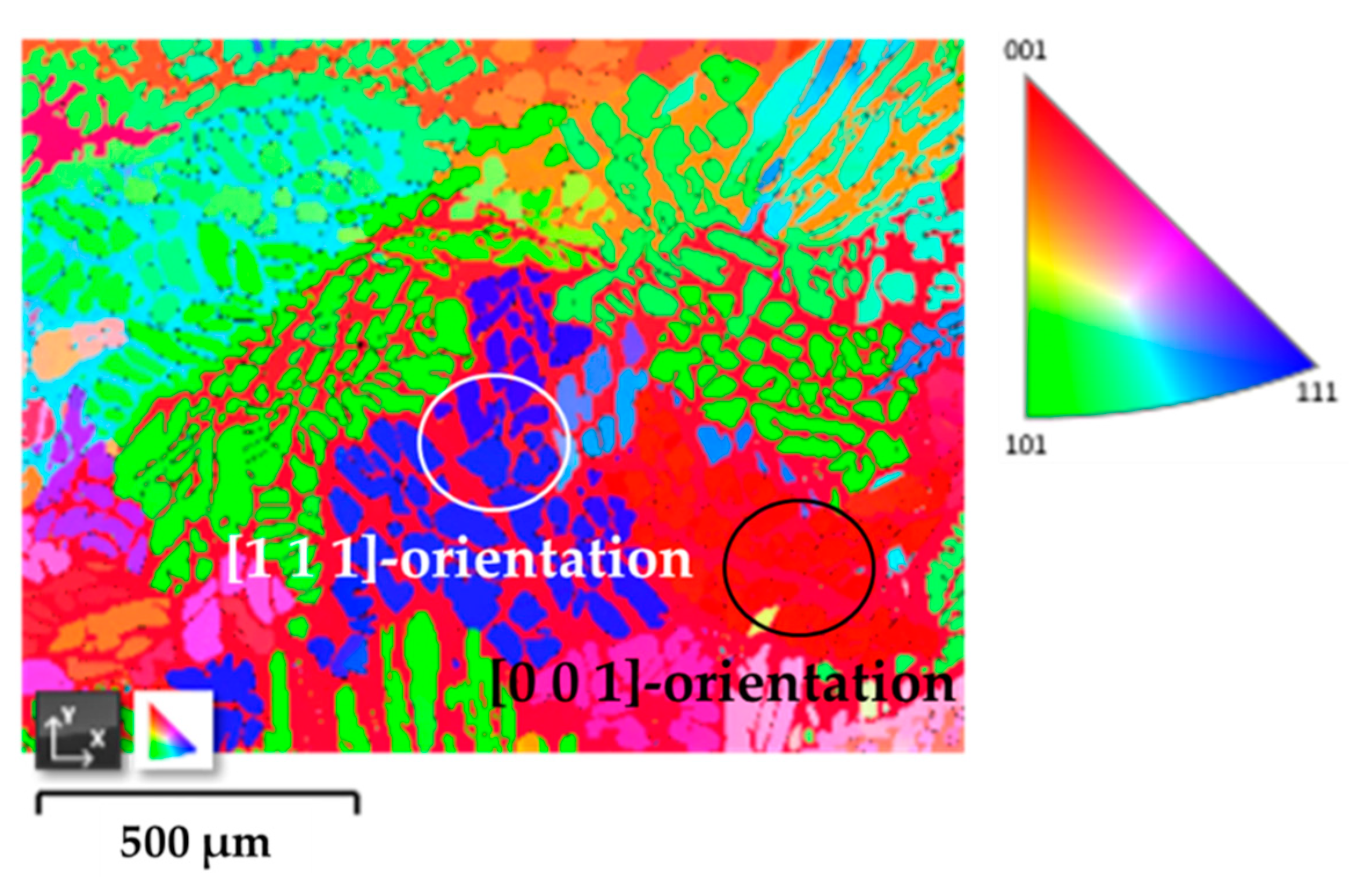
2. Materials and Methods

Studied austenite crystals were from commercial austenite-ferrite duplex stainless steel obtained from Baosteel stainless steel Co., Ltd (Shanghai, China). The chemical compositions and stacking fault energy of the tested austenite phase are shown in Table 1. According to the calculation based on the research result Dai et al. [29], SFE of austenite phase at room temperature was estimated to be 58–73 mJ/m2. More information was described in detail previously [30]. As-received material was solution-annealed at 1050 °C for 12 h followed by water quenching to obtain recrystallized coarse grain. Crystallographic orientations of austenite grains were characterized by Electron Backscatter Diffraction analysis (EBSD, Oxford Instruments). Figure 1 shows the EBSD inverse pole figure to Z axis (IPF-Z) of austenite and ferrite grains in the studied DSS. As the surrounded black and white circles show in Figure 1, austenite grains, which had Euler Angles of [263° 3.1° 85.4°] and [49.9° 47.9° 40.3°], were selected for micro-pillar fabrication. The Miller factor of the selected grains, [h k l], could be calculated by:
g = ( u r h v s k w t l ) = ( cos φ sin φ 0 sin φ cos φ 0 0 0 1 ) ( 1 0 0 0 cos θ sin θ 0 sin θ cos θ ) ( cos ψ sin ψ 0 sin ψ cos ψ 0 0 0 1 ) = ( cos ψ cos φ sin ψ sin φ cos θ sin ψ cos θ + cos ψ sin φ cos θ sin φ sin θ cos ψ sin φ sin ψ cos φ cos θ sin ψ sin φ + cos ψ cos θ cos φ sin θ sin ψ sin θ cos ψ sin θ cos θ )
where (ψ θ φ) is Euler Angle of selected grain. The actual crystallographic orientation of the selected austenite grains closed to ideal [0 0 1]- and [1 1 1]-orientations were more inclined to [1 0 17]- and [12 14 17]-orientations, respectively. Micro-pillars were fabricated using a dual-beam Focused Ion Beam with Scanning Electron Microscope (SEM/FIB Crossbeam System, FEI Helios Nanolab 600i, FEI Ltd., Hillsboro, Oregon, USA). The final pillars had a length-to-diameter ratio around 3 with 5 μm diameter. Taper angles were ensured to be less than 5°, as confirmed by SEM. Compression tests were carried out at room temperature using Agilent Nano Indenter G200 (Agilent Technologies Inc., Santa Rosa, CA, USA) with a 20 μm diameter flat-ended diamond tip. The tests were performed under a constant loading rate of 0.1 mN/s up to the maximum penetration depth (strain) of 5 μm (33%). The compression engineering stress (σ) - strain (ε) curves of tested micro-pillars were converted from the compressive load (P) - displacement (h) data by the average value of top, middle and bottom cross-sectional area and the height of the micro-pillar. Finally, lamellae with thickness less than 100 nm, fabricated from deformed pillars by FIB milling, were observed by transmission electron microscopy (TEM, JEOL JEM-2100, JEOL Ltd., Tokyo, Japan). The cross sections of TEM specimens were perpendicular to the slip planes of the slip systems to analyze the activated deformation carriers and their interactions.

3. Results

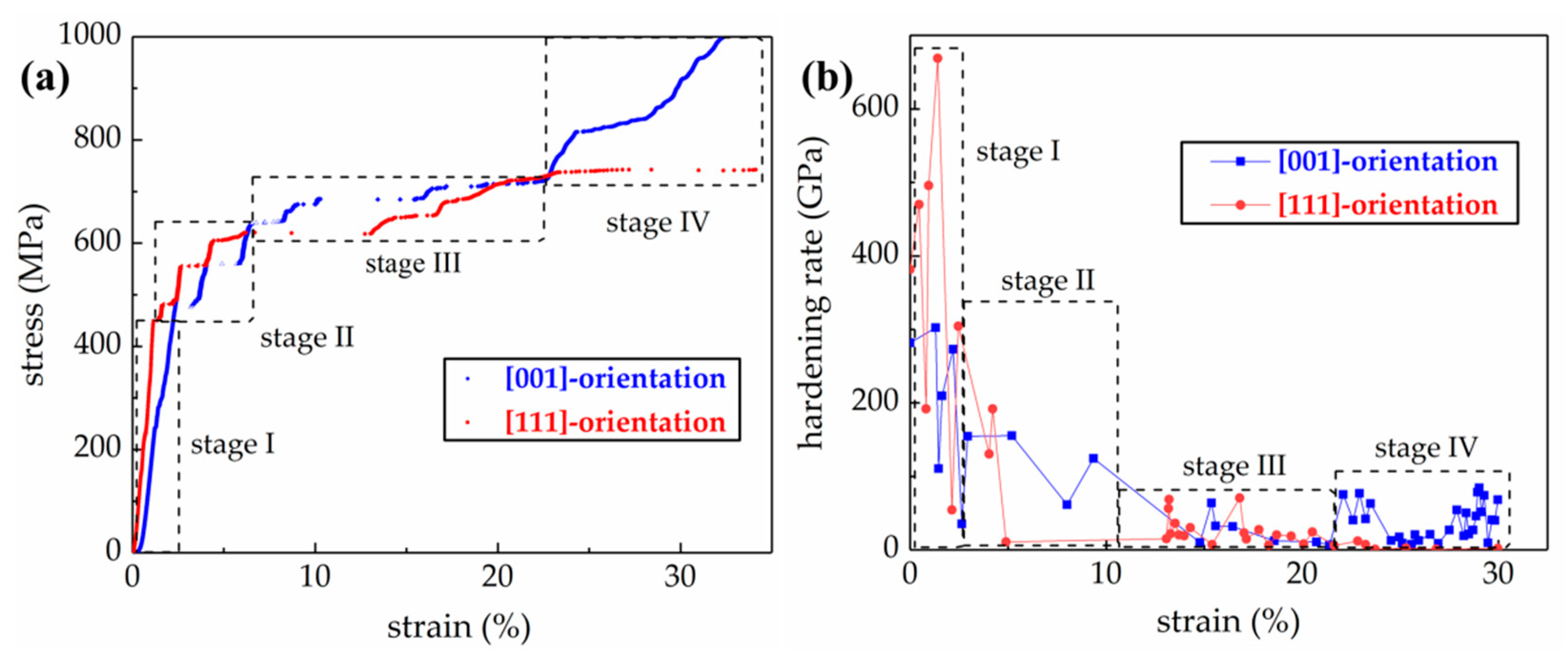
3.1. Stress-Strain Curves

Figure 2a,b show σ-ε curves and the strain hardening rate (dσ/dε) at some strain points of tested [0 0 1]- and [1 1 1]-oriented austenite micro-pillars, respectively. At the beginning, both [0 0 1]- and [1 1 1]-oriented austenite micro-pillars experienced elastic deformation stage, i.e., stage I. Young’s modulus (E) for the [0 0 1]- and [1 1 1]-oriented austenite micro-pillars (197.2 GPa and 273.3 GPa, respectively) was crystallographic orientation-dependent. After yielding, both [0 0 1]- and [1 1 1]-oriented austenite micro-pillars presented small strain bursts, which implied the processes of plastic deformation, named as stage II. In this stage, plastic deformation proceeded by discrete strain bursts, and the average and total strain burst sizes were 1.01% and 5.07% for the [0 0 1]-oriented pillar and 0.88% and 1.75% for the [1 1 1]-oriented pillars before the strain reached 7.7% for the [0 0 1]-oriented micro-pillar and 4.3% for the [1 1 1]-oriented pillar. Between the strain bursts in stage II, flow stresses surged drastically with dσ/dε values closing Young’s modulus. Specifically, the dσ/dε values of [0 0 1]- and [1 1 1]-oriented micro-pillars reached 204.4 GPa at 2.46% strain and 154.5 GPa at 2.95% strain, respectively. This phenomenon is called exhaustion hardening. After that, the flow stresses of both pillars climbed moderately, i.e., stage III. In this stage, both pillars possessed lower hardening rate, having the maximum rate of 32.51 GPa at 15.58% strain for the [0 0 1]-orientation and 36.30 GPa at 13.52% strain for the [1 1 1]-orientation. Apparent differences in stress-strain responses dependent on crystallographic orientation could be observed after the strain reached 20%, considered as stage IV. Differently from the stable deformation behavior up to strain larger than 30% of the [1 1 1]-oriented pillar, [0 0 1]-oriented pillars experienced a sharp climb again in flow stress at strain larger than 22%, similar to the deformation during stage II. For example, the rate of the [0 0 1]-oriented micro-pillar reached 76.9 GPa at 22.91%, while that of the [1 1 1]-orientation was 11.9 GPa at 22.83% strain.

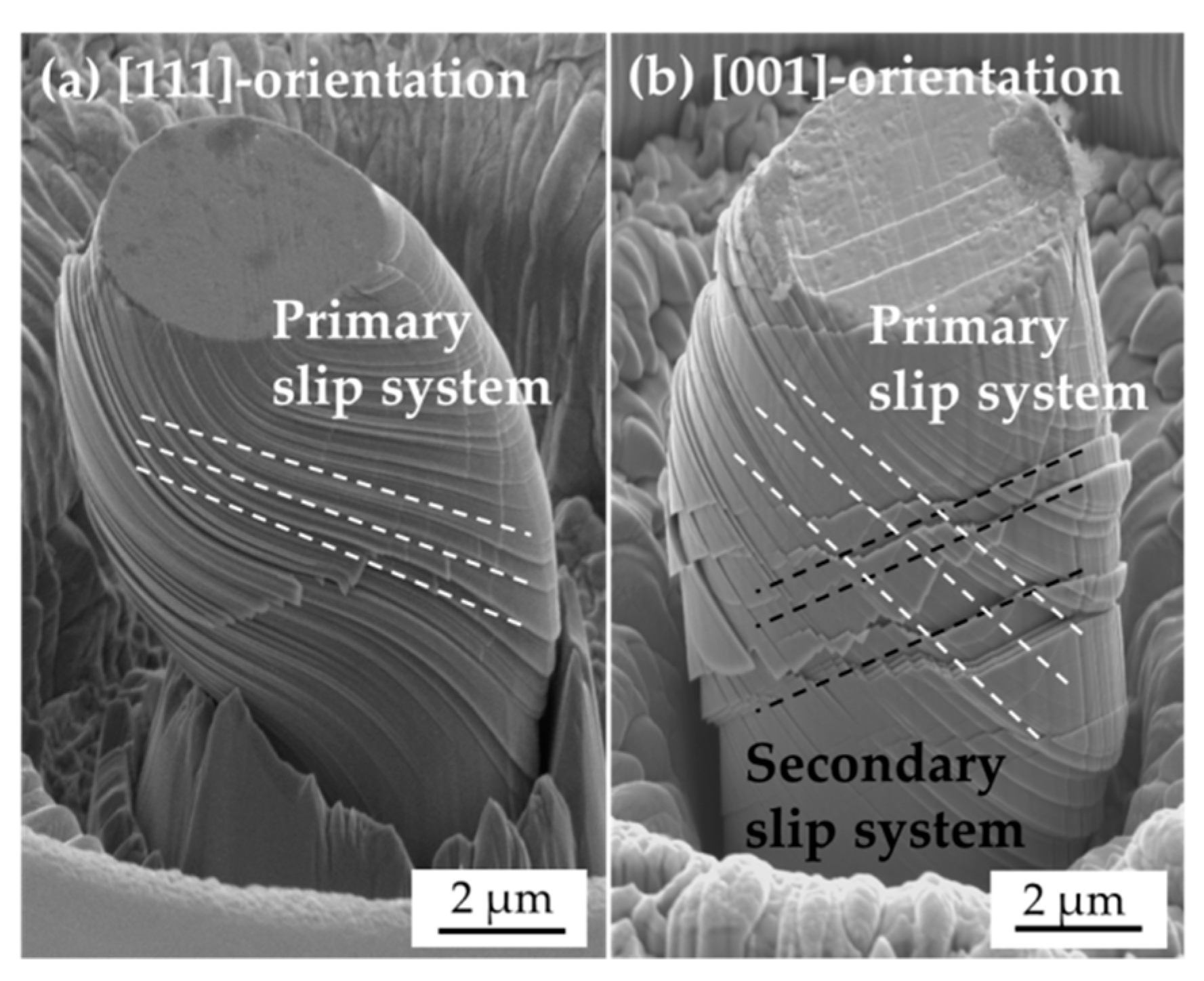
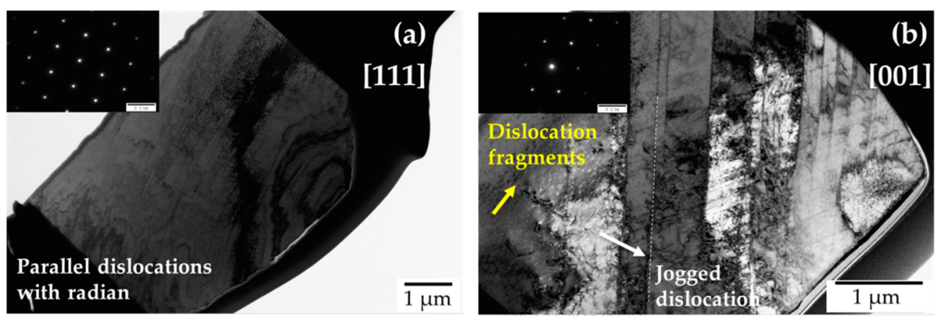
3.2. Microstructure Observation
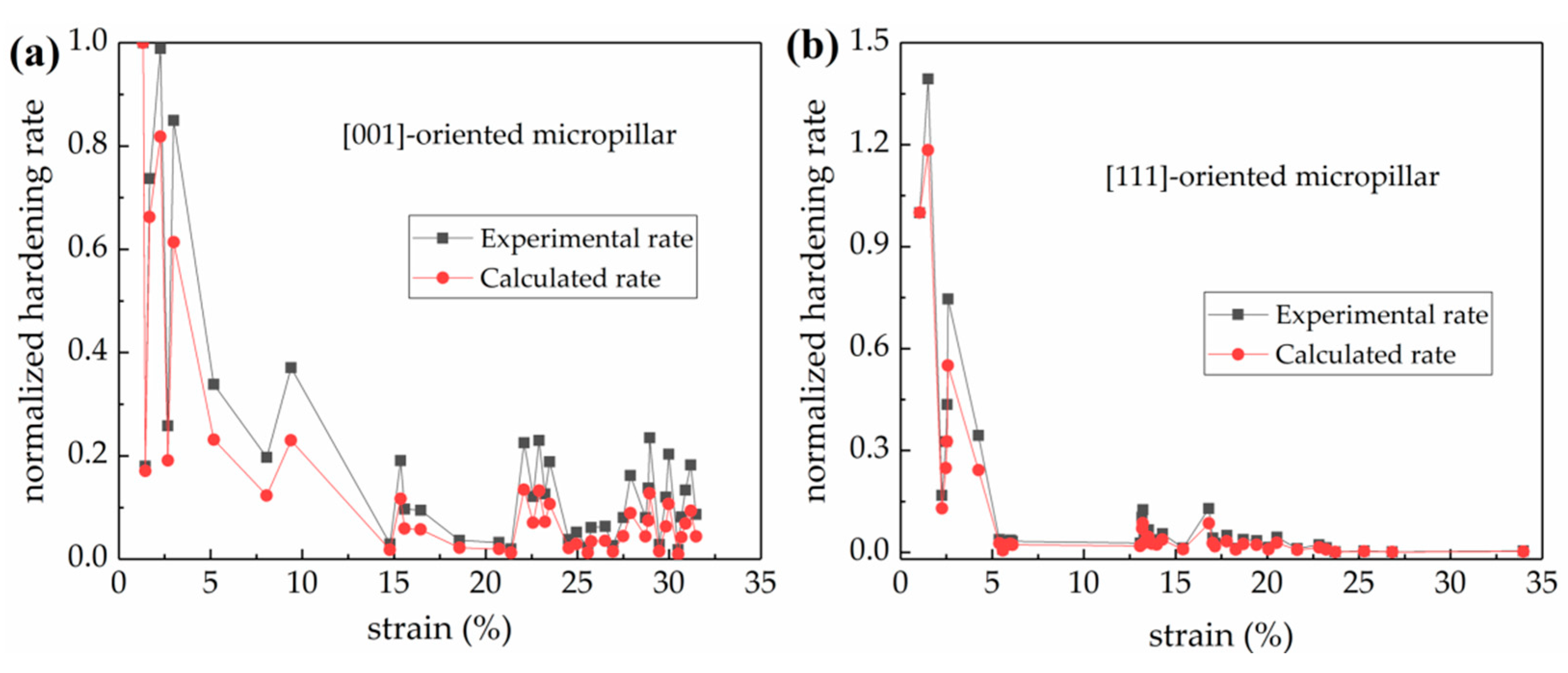
Figure 3 shows the SEM microtopography of compressed austenite micro-pillars. After dramatic deformation with strain larger than 30%, distinct glide traces of inclined slip planes were visible and concentrated on the top and middle of both [0 0 1]- and [1 1 1]-oriented deformed micro-pillar surface. However, the appearance of slip planes on the surface was also crystallographic orientation-dependent. As presented in Figure 3a, in the [1 1 1]-oriented pillar, surface steps were concentrated on one slip plane exclusively and uniformly, i.e., presented in the primary slip system. The repeated gliding on the same plane led to obvious lattice torsion. The angle between activated slip planes and the normal direction of experimental pillar was measured to be 63.9°. By contrast, the surface of the [0 0 1]-oriented deformed micro-pillar presented two glide traces on different slip systems, marked by white and black dashed lines, as shown in Figure 3b, which indicated that, besides the primary slip system, the second set of slip planes was activated. Because of the relatively homogeneous distribution and smaller spacing, the slip traces marked by red dashed lines were considered as the primary slip system, which had a deviation angle of 58.5°. Several slip lines with different angles were found near the top of the [1 1 1]-oriented micro-pillar, indicating that another slip system was activated, which could be explained by the inhomogeneous distribution of compression stress near the top surface of the micro-pillar. The same phenomenon can be observed in another study [31]. The effect of this slipping on strain hardening behavior was negligible to this study.
Table 2 lists the Schmid factor and deviation angle of all potential slip systems under the theoretical and experimented loading conditions. The ideal [1 1 1]-oriented austenite micro-pillar had the same tendency on six slipping systems. Practical direction of the studied [1 1 1]-oriented austenite pillar was more inclined to [12 14 17]-orientation, and the deviation angle (8°), smaller than 10°, was acceptable. Slip trace analysis indicated that (−1 1 1)[1 0 1] slip direction had the highest Schmid factor of 0.36, i.e., proved to be the primary activate slip system. The angle between the normal of the slip plane and the compression axis should be 63.9° by the calculation result of the geometric relationship. The measured angle was 61.8°, however, having a very small difference, which could be caused by the measurement issue, and the deviation was acceptable. The tested [0 0 1]-oriented micro-pillar exhibited two obvious slip systems during the deformation. The actual compressive axis along the [1 0 18] direction had tendentious slip systems of (−1 1 1)[1 0 1] and (1 1 −1)[0 1 1] with Schmid factors of 0.41 and 0.38., respectively. The inclined angle of above two slip system was observed to be 58.5°, in good agreement with the theoretical angle of 57°. The activation of the second slip system was attributed to the increase of the resolved shear stress on the second slip plane with increasing strain.
Figure 4 illustrates cross-sectional TEM bright field images and the selected area diffraction pattern of [1 1 1]- and [0 0 1]-oriented compressed micro-pillars. One can note from both microstructure characterization results that clear slip traces could be observed, and no transformation-induced twinning and martensite phase could be found due to high stacking fault energy of the tested austenite crystals. For [1 1 1] orientation, the slip traces were parallel in the exclusive glide plane, and the distribution was uniform and dense on the top of micro-pillar, as shown in Figure 4a. Due to the crystal lattice twist, the slip bands exhibited arc-shaped traces, i.e., had a radian. Compared with the arc-shaped traces of the [1 1 1]-oriented pillar, the slip traces of compressed [0 0 1]-orientation were in the shape of straight lines. Two slip planes with an intersect angle of 69.57° could be observed, indicating that the secondary slip system was activated. Differently from the whole slip traces with radian in the [1 1 1]-oriented micro-pillar, some of those in the [0 0 1] orientation were inflected, which was considered to be caused by jogged dislocation, marked by white arrows in Figure 4b. The caused dislocation stairs could also be observed on the surface of the deformed micro-pillar characterized by SEM. Some short dislocation fragments could be observed near the bottom of micro-pillar, marked by yellow arrows in Figure 4b, believed to be independent of deformation, i.e., presented in the initial dislocation.

4. Discussion

4.1. Elastic Deformation

From the above we can see that for single crystal micro-pillars, the mechanical responses were dependent on the crystallographic orientation. During the elastic deformation stage, the [1 1 1]-oriented micro-pillar possessed a higher Young’s modulus of 273.3 GPa than the [0 0 1]-orientation with that of 197.2 GPa. The increase in E111 can be explained by the anisotropy parameter [32]:
A h k l = h 2 k 2 + k 2 l 2 + l 2 h 2 ( h 2 + k 2 + l 2 ) 2
and thus, A111 and A001 have the largest discrepancy of 0 and 1/3, respectively. The relationship between Ehkl and Ahkl can be expressed by:
1 E h k l = S 11 + ( 2 S 12 2 S 11 + S 44 ) A h k l
where S11, S12 and S44 are three independent factors of a cubic system, taken as 10.7 × 10⁻³, 4.25 × 10⁻³ and 8.6 × 10⁻³, respectively [33]. Hence, E111 should be much higher than E001, which is in accordance with our experimental result.

4.2. Plastic Deformation

From Figure 2, the yield stresses of [0 0 1]- and [1 1 1]-oriented austenite micro-pillars were 426.9 MPa and 492.5 MPa, respectively. Combined with the Schmid factors of the primary slip system verified by the deformed microstructure observation, the Critical Shear Stresses (CRSS) of [0 0 1]- and [1 1 1]-oriented micro-pillars were calculated to be 183.6 MPa and 173.3 MPa, respectively. The average value of CRSS was calculated to be 178.5 MPa, and the deviation was about 5%, which was negligible here. Other research has also shown that the CRSS value is related to the materials and independent of grain orientation [9,23]. After yielding, the engineering stress-strain curves of both [0 0 1]- and [1 1 1]-oriented micro-pillars exhibited multiple plastic deformation stages with different strain hardening rates. Compared with the slight strain hardening of the [1 1 1]-oriented micro-pillar from stage III, the deformation response of the [0 0 1]-orientation showed a climb in stage IV. Based on SEM and TEM observation of the tested austenite micro-pillars, the deformed microstructure was characterized by a pronounced dislocation glide plane, which led to the formation of crystallographic slip bands on the activated slip systems, i.e., microband-induced plasticity, MBIP. The tested [1 1 1]-oriented micro-pillar exhibited dislocation glide traces with the same direction while the [0 0 1]-orientation revealed the secondary slip system. Hence, the activation of the secondary slip system induced higher flow stresses.

4.3. Flow Stress Expression

The total flow stress (σt) after the yielding can be expressed by:
σ t = σ y + σ SH ( ε )
where σy is the yield stress and σ(ε) is the plasticity-driven strain hardening capacity in the flow stress. The first term, σy, representing the activation of perfect dislocation in the present tests, can be calculated by [8]:
σ y = 2 α 0 G b perfect Λ
where α0 is a constant describing the character of dislocation, considered as 0.5 for pure edge dislocations here [8], bp is the magnitude of the Burgers vector for perfect dislocation, considered as 0.256 nm for face-centered crystal lattice [8,13] and G is the shear modulus, which was taken as 105.1 GPa and 75.8 GPa for [0 0 1]-oriented and [1 1 1]-oriented micro-pillars, respectively. Additionally, Λ mentioned before is defined as the “mean free path”, which is the average feasible distance of dislocations before they stored or annihilated [34]. The values of Λ were calculated to be 319.7 nm and 206.1 nm for the [1 1 1]- and [0 0 1]-oriented micro-pillars, respectively.
For pure dislocation-dislocation mediated plasticity steels, the change of flow stress can be expressed by the evolution of dislocation density, ρ, invariably [35]:
σ SH ( ε ) = α G b ρ
where α is a factor related to the material, generally ranged from 0.3 to 0.5 [35]. Differentiating both sides of Equation (6) to the strain, the strain hardening rate, Θ = d σ d ε , can be expressed as:
σ Θ = ( α G ) 2 2 b Λ
where the rate of dislocation accumulation to the strain can be formally expressed as d ρ d ε = 1 b Λ . Hence, the strain hardening itself can be expressed as:
Θ = ( α G ) 2 D Λ
where D is the mean dislocation spacing, expressed as D = 1 / ρ . According to Equation (8), the strain hardening rate of the research material during plastic deformation is proportional to the ratio of the mean dislocation spacing and the mean free path. The trend of experimental and calculated strain hardening rates of [0 0 1]- and [1 1 1]-oriented micro-pillars are presented in Figure 5a,b, respectively. For better comparison, all experimental and calculated strain hardening rates were standardized by the strain hardening rate at the yield point. The calculation results had a good description of the trend of strain hardening rate.
Micro-pillar compression tests combined with SEM/TEM observation were carried out in this work to describe the differences in mechanical responses and properties of [0 0 1]- and [1 1 1]-oriented single crystal austenite micro-pillars with high SFE value. Another task will be to explore the deformation behaviors of ferrite grains and the effect of grain boundaries on the mechanical property by the same experimental method. The research results can provide a local deformation mechanism support for the overall mechanical description and safety prediction of duplex stainless steel components.

5. Conclusions

The deformation behaviors and micro-structure evolution of austenite micro-pillars were investigated by a compression test and SEM and TEM observation. The main conclusions are:
  • The elastic modulus of 5 μm austenite pillars with [0 0 1]- and [1 1 1]-orientation was 197.2 GPa and 273.3 GPa, respectively, and was crystallographic orientation-dependent. The calculated CRSS values derived from the experiments were about 178.5 MPa for both [0 0 1]- and [1 1 1]-oriented micro-pillars, relating to the activation of dislocation gliding.
  • Deformation microstructures of both micro-pillars were characterized by pronounced planar slip. The slipping band structure undergoes refinement during straining, resulting in the strain hardening behavior.
  • Higher flow stress and unstable strain hardening behavior in [0 0 1]-oriented austenite micro-pillars were assumed to be caused by the easy activation of secondary slip systems.

Author Contributions

Conceptualization, Y.-F.J. and F.-Z.X.; methodology, Y.-Y.C. and Y.-F.J.; software, Y.-Y.C.; validation, Y.-Y.C. and Y.-F.J.; formal analysis, Y.-Y.C.; investigation, Y.-Y.C.; resources, Y.-F.J. and F.-Z.X.; data curation, Y.-Y.C. and Y.-F.J.; writing—original draft preparation, Y.-Y.C.; writing—review and editing, Y.-F.J.; visualization, Y.-Y.C. and Y.-F.J.; supervision, F.-Z.X.; project administration, F.-Z.X.; funding acquisition, Y.-F.J. All authors have read and agreed to the published version of the manuscript.

Funding

This work was sponsored by the National Natural Science Foundation of China (51975211, 51835003) and Shanghai Rising-Star Program (20QA1402500).

Data Availability Statement

Not applicable.

Conflicts of Interest

The authors declare no conflict of interest.

Abbreviations

SymbolDefinitionValueUnitReference
[0 0 1][1 1 1]
SFEStacking fault energy58–73mJ/m2[21]
EYoung’s modulus197.2273.3GPa
σyYield stress
αConstant0.5 [8]
bBurgers vector0.256nm[8,13]
GShear modulus105.175.8GPa
CRSSCritical shear stress175.8MPa
ρDislocation density
ɅMean free path206.1319.7nm
ΘStrain hardening rate
DMean dislocation spacing

References

  1. Weibull, I. Duplex stainless steels and their application, particularly in centrifugal separators. Part A History & Development. Mater. Des. 1987, 8, 35–40. [Google Scholar]
  2. Terao, H. Structure and mechanical properties of high-manganese dual-phase steels. J. Mater. Sci. 1986, 21, 1715–1720. [Google Scholar] [CrossRef]
  3. Yanru, S.; Guangjian, Y.; Sujuan, G. Micromechanics finite element analysis of local micro-deformation behaviour of duplex stainless steel under uniaxial tension. Chin. Q. Mech. 2020, 41, 29–38. [Google Scholar]
  4. Liu, J.-H. Quantitative deformation measurements and analysis of the ferrite-austenite banded structure in a 2205 duplex stainless steel at 250 °C. Chin. Phys. B 2018, 27, 038102. [Google Scholar] [CrossRef]
  5. Nimaga, O.G.; Cheng, G.J.; Yen, H.W.; Huang, M.X. Large strain burst induced by martensitic transformation in austenitic micropillars. Scr. Mater. 2017, 137, 64–68. [Google Scholar] [CrossRef]
  6. Dimiduk, D.M.; Uchic, M.D.; Parthasarathy, T.A. Size-affected single-slip behavior of pure nickel microcrystals. Acta Mater. 2005, 53, 4065–4077. [Google Scholar] [CrossRef]
  7. Bai, S.; Xiao, W.; Niu, W.; Li, D.; Liang, W. Microstructure and mechanical properties of a medium-Mn steel with 1.3 GPa-strength and 40%-ductility. Materials 2021, 14, 2233. [Google Scholar] [CrossRef]
  8. Seo, E.J.; Kim, J.K.; Cho, L.; Mola, J.; Oh, C.Y.; De Cooman, B.C. Micro-plasticity of medium Mn austenitic steel: Perfect dislocation plasticity and deformation twinning. Acta Mater. 2017, 135, 112–123. [Google Scholar] [CrossRef]
  9. Choi, W.S.; De Cooman, B.C.; Sandlöbes, S.; Raabe, D. Size and orientation effects in partial dislocation-mediated deformation of twinning-induced plasticity steel micro-pillars. Acta Mater. 2015, 98, 391–404. [Google Scholar] [CrossRef]
  10. Yang, G.; Kim, J.-K. An overview of high yield strength twinning-induced plasticity steels. Metals 2021, 11, 124. [Google Scholar] [CrossRef]
  11. Zhi, H.; Zhang, C.; Guo, Z.; Antonov, S.; Su, Y. Outstanding tensile properties and their origins in twinning-induced plasticity (TWIP) steels with gradient substructures. Materials 2020, 13, 1184. [Google Scholar] [CrossRef] [PubMed] [Green Version]
  12. Yoo, J.D.; Park, K.-T. Microband-induced plasticity in a high Mn–Al–C light steel. Mater. Sci. Eng. A 2008, 496, 417–424. [Google Scholar] [CrossRef]
  13. Welsch, E.; Ponge, D.; Hafez Haghighat, S.M.; Sandlöbes, S.; Choi, P.; Herbig, M.; Zaefferer, S.; Raabe, D. Strain hardening by dynamic slip band refinement in a high-Mn lightweight steel. Acta Mater. 2016, 116, 188–199. [Google Scholar] [CrossRef]
  14. Kim, S.-D.; Park, J.Y.; Park, S.-J.; Jang, J.h.; Moon, J.; Ha, H.-Y.; Lee, C.-H.; Kang, J.-Y.; Shin, J.-H.; Lee, T.-H. Direct observation of dislocation plasticity in high-Mn lightweight steel by in-situ TEM. Sci. Rep. 2019, 9, 15171. [Google Scholar] [CrossRef] [PubMed]
  15. Park, K.-T. Tensile deformation of low-density Fe–Mn–Al–C austenitic steels at ambient temperature. Scr. Mater. 2013, 68, 375–379. [Google Scholar] [CrossRef]
  16. Qayyum, F.; Guk, S.; Prahl, U. Studying the damage evolution and the micro-mechanical response of X8CrMnNi16-6-6 TRIP steel matrix and 10% zirconia particle composite using a calibrated physics and crystal-plasticity-based numerical simulation model. Crystals 2021, 11, 759. [Google Scholar] [CrossRef]
  17. Qayyum, F.; Guk, S.; Schmidtchen, M.; Kawalla, R.; Prahl, U. Modeling the local deformation and transformation behavior of cast X8CrMnNi16-6-6 TRIP steel and 10% Mg-PSZ composite using a continuum mechanics-based crystal plasticity model. Crystals 2020, 10, 221. [Google Scholar] [CrossRef] [Green Version]
  18. Qayyum, F.; Guk, S.; Prüger, S.; Schmidtchen, M.; Saenko, I.; Kiefer, B.; Kawalla, R.; Prahl, U. Investigating the local deformation and transformation behavior of sintered X3CrMnNi16-7-6 TRIP steel using a calibrated crystal plasticity-based numerical simulation model. Int. J. Mater. Res. 2020, 111, 392–404. [Google Scholar] [CrossRef]
  19. Chowdhury, P.; Canadinc, D.; Sehitoglu, H. On deformation behavior of Fe-Mn based structural alloys. Mater. Sci. Eng. R Rep. 2017, 122, 1–28. [Google Scholar] [CrossRef]
  20. Kireeva, I.V.; Chumlyakov, Y.I.; Vyrodova, A.V.; Pobedennaya, Z.V.; Karaman, I. Effect of twinning on the orientation dependence of mechanical behaviour and fracture in single crystals of the equiatomic CoCrFeMnNi high-entropy alloy at 77K. Mater. Sci. Eng. A 2020, 784, 139315. [Google Scholar] [CrossRef]
  21. Soares, G.C.; Gonzalez, B.M.; de Arruda Santos, L. Strain hardening behavior and microstructural evolution during plastic deformation of dual phase, non-grain oriented electrical and AISI 304 steels. Mater. Sci. Eng. A 2017, 684, 577–585. [Google Scholar] [CrossRef]
  22. Uchic, M.D.; Shade, P.A.; Dimiduk, D.M. Plasticity of micrometer-scale single crystals in compression. Annu. Rev. Mater. Res. 2009, 39, 361–386. [Google Scholar] [CrossRef] [Green Version]
  23. Choi, W.S.; Sandlöbes, S.; Malyar, N.V.; Kirchlechner, C.; Korte-Kerzel, S.; Dehm, G.; De Cooman, B.C.; Raabe, D. Dislocation interaction and twinning-induced plasticity in face-centered cubic Fe-Mn-C micro-pillars. Acta Mater. 2017, 132, 162–173. [Google Scholar] [CrossRef]
  24. Wu, S.Z.; Yen, H.W.; Huang, M.X.; Ngan, A.H.W. Deformation twinning in submicron and micron pillars of twinning-induced plasticity steel. Scr. Mater. 2012, 67, 641–644. [Google Scholar] [CrossRef]
  25. Timofeeva, E.E.; Panchenko, E.Y.; Chumlyakov, Y.I.; Maier, H.J.; Gerstein, G. Peculiarities of high-temperature superelasticity in Ni–Fe–Ga single crystals in compression. Tech. Phys. Lett. 2017, 43, 320–323. [Google Scholar] [CrossRef]
  26. Yilmaz, H.; Williams, C.J.; Derby, B. Size effects on strength and plasticity of ferrite and austenite pillars in a duplex stainless steel. Mater. Sci. Eng. A. 2020, 793, 8. [Google Scholar] [CrossRef]
  27. Maaß, R.; Uchic, M.D. In-Situ characterization of the dislocation-structure evolution in Ni micro-pillars. Acta Mater. 2012, 60, 1027–1037. [Google Scholar] [CrossRef]
  28. Frick, C.P.; Clark, B.G.; Orso, S.; Schneider, A.S.; Arzt, E. Size effect on strength and strain hardening of small-scale [111] nickel compression pillars. Mater. Sci. Eng. A 2008, 489, 319–329. [Google Scholar] [CrossRef]
  29. Qi-Xun, D.; An-Dong, W.; Xiao-Nong, C.; Xin-Min, L. Stacking fault energy of cryogenic austenitic steels. Chin. Phys. 2002, 11, 596–600. [Google Scholar] [CrossRef]
  30. Cui, Y.Y.; Jia, Y.F.; Xuan, F.Z. Micro-deformation evolutions of the constituent phases in duplex stainless steel during cyclic nanoindentation. Sci. Rep. 2018, 8, 6199. [Google Scholar] [CrossRef]
  31. Zhu, Q.; Wu, X.; Cao, L.; Zhang, L.; Liu, Y.; Liu, S.; Liu, Q. In-Situ micro-compression of single-crystal aluminum alloy 6063. Mater. Sci. Eng. A 2020, 775, 138974. [Google Scholar] [CrossRef]
  32. Kang, S.; Jung, Y.-S.; Yoo, B.-G.; Jang, J.-i.; Lee, Y.-K. Orientation-dependent indentation modulus and yielding in a high Mn twinning-induced plasticity steel. Mater. Sci. Eng. A 2012, 532, 500–504. [Google Scholar] [CrossRef]
  33. Stinville, J.C.; Tromas, C.; Villechaise, P.; Templier, C. Anisotropy changes in hardness and indentation modulus induced by plasma nitriding of 316L polycrystalline stainless steel. Scr. Mater. 2011, 64, 37–40. [Google Scholar] [CrossRef]
  34. Devincre, B.; Hoc, T.; Kubin, L. Dislocation mean free paths and strain hardening of crystals. Science 2008, 320, 1745–1748. [Google Scholar] [CrossRef]
  35. Kocks, U.F.; Mecking, H. Physics and phenomenology of strain hardening: The FCC case. Prog. Mater. Sci. 2003, 48, 171–273. [Google Scholar] [CrossRef]
Figure 1. EBSD inverse pole figure to Z axis (IPF-Z) of austenite and ferrite grains in the studied DSS.
Metals 11 01179 g001
Figure 2. (a) The stress-strain curves and (b) the strain hardening rates at some strain points of [0 0 1]- and [1 1 1]-oriented austenite micro-pillars.
Metals 11 01179 g002
Figure 3. SEM morphology of compressed (a) [1 1 1]-oriented and (b) [0 0 1]-oriented austenite micro-pillars after 33% strain.
Metals 11 01179 g003
Figure 4. TEM bright images show (a) abundant microbands in deformed [1 1 1]-oriented pillar and (b) intersecting bands in deformed [0 0 1]-oriented pillars after 33% strain.
Metals 11 01179 g004
Figure 5. Experimental and calculated normalized strain hardening rates of (a) [0 0 1]- oriented micro-pillar and (b) [1 1 1]-oriented micro-pillar.
Metals 11 01179 g005
Table 1. Chemical compositions and stacking fault energy of the tested austenite phase.
Chemical Composition (wt.%)Characteristics
CCrNiMoMnSiSFE (mJ/m2) [29]
0.05625.057.812.910.810.3858–73
Table 2. The corresponding Schmid factor and angles of slip systems for perfect dislocation under different loading orientations.
Slip System[0 0 1]-Oriented Grain[1 0 18]-Oriented Grain[1 1 1]-Oriented Grain[12 14 17]-Oriented Grain
Schmid FactorAngleSchmid FactorAngleSchmid FactorAngleSchmid FactorAngle
[1 0 1]( −1 1 1)0.4154.70.41570.2770.50.3663.9
[0 −1 1]( −1 1 1)0.4154.70.3857--0.0363.9
[1 1 0](-1 1 1)--0.02570.2770.50.3263.9
[0 −1 1](1 1 1)0.4154.70.4352.3--0.077.9
[−1 1 0](1 1 1)--0.0252.3--0.067.9
[1 0 -1](1 1 1)0.4154.70.4152.3--0.147.9
[−1 0 1](1 −1 1)0.4154.70.452.6--0.0570.4
[0 1 1](1 −1 1)0.4154.70.4352.60.2770.50.2970.4
[1 1 0](1 −1 1)--0.0352.60.2770.50.2570.4
[1 0 1](1 1 -1)0.4154.70.457.20.2770.50.1777.6
[0 1 1](1 1 −1)0.4154.70.3857.20.2770.50.1977.6
[1 −1 0](1 1 −1)--0.0257.2--0.0177.6
Publisher’s Note: MDPI stays neutral with regard to jurisdictional claims in published maps and institutional affiliations.

