
Tool Wear Analysis during Ultrasonic Assisted Turning of Nimonic-90 under Dry and Wet Conditions


1
Department of Mechanical Engineering, Indian Institute of Technology-Ropar, Rupnagar 140001, India
2
CFAA, University of the Basque Country (UPV/EHU), Parque Tecnológico de Bizkaia 202, 48170 Bilbao, Spain
3
Department of Mechanical Engineering, University of the Basque Country (UPV/EHU), Plaza Torres de Quevedo s/n, 48013 Bilbao, Spain
4
Advanced Manufacturing Laboratory, Institute of Infrastructure Technology Research and Management (IITRAM), Ahmedabad 380026, India
*
Authors to whom correspondence should be addressed.
Metals 2021, 11(8), 1253; https://0-doi-org.brum.beds.ac.uk/10.3390/met11081253
Submission received: 7 July 2021
/
Revised: 4 August 2021
/
Accepted: 5 August 2021
/
Published: 7 August 2021
(This article belongs to the Special Issue Optimization and Analysis of Metal Cutting Processes)
Abstract
:Nickel-based superalloys are widely used in the aerospace, automotive, marine and medical sectors, owing to their high mechanical strength and corrosion resistance. However, they exhibit poor machinability due to low thermal conductivity, high shear modulus, strain hardening, etc. Various modifications have been incorporated into existing machining techniques to address these issues. One such modification is the incorporation of ultrasonic assistance to turning operations. The assisted process is popularly known as ultrasonic assisted turning (UAT), and uses ultrasonic vibration to the processing zone to cut the material. The present article investigates the effect of ultrasonic vibration on coated carbide tool wear for machining Nimonic-90 under dry and wet conditions. UAT and conventional turning (CT) were performed at constant cutting speed, feed rate and depth of cut. The results show that the main wear mechanisms were abrasion, chipping, notch wear and adhesion of the built-up edge in both processes. However, by using a coolant, the formation of the built-up edge was reduced. CT and UAT under dry conditions showed an approximate reduction of 20% in the width of flank wear compared to CT and UAT under wet conditions. UAT showed approximate reductions of 6–20% in cutting force and 13–27% in feed force compared to the CT process. The chips formed during UAT were thinner, smoother and shorter than those formed during CT.
1. Introduction
Nickel-based superalloys exhibit good mechanical strength and corrosion resistance. Due to their superior properties, they are used in aircraft gas turbines, power plants, engines, medical applications, space vehicles, etc. However, some characteristics such as work hardening during machining, localisation of shear in the chips and tendency of built-up edge (BUE) formation make them poor for machining. Moreover, these characteristics produce high temperatures and stresses and increase tool wear, cutting forces, power consumption, etc. [1]. Several researchers have applied various methods to reduce such problems in the machining of superalloys. These methods incorporate hybridisation to the existing machining process, modification of the microstructure of the workpiece material, etc. Some hybrid machining processes, such as ultrasonic vibration-assisted [2], induction-assisted [3], LASER-assisted [4], gas-assisted [5] and minimum quantity lubrication (MQL)-assisted [6,7] machining are used to improve the machinability of those alloys.
Ultrasonic-assisted machining uses ultrasonic vibration to the cutting zone [2]. The vibration is superimposed on the cutting action of the tool. Ultrasonic vibration has been implemented to various conventional machining processes such as turning, milling and drilling. Muhammad et al. [8] performed UAT of the titanium base alloy Ti 6Al 7Zr 6Mo 0.9La to analyse forces and chips. The UAT showed an approximate reduction of 74% in cutting force than in CT. The chips formed in UAT were shorter, thinner and discontinuous compared with CT. Likewise, Khanna et al. [9] observed in the UAT of Inconel 718 that surface roughness and power consumption significantly reduce compared to CT. Puga et al. [10] studied surface quality in the UAT of cast and wrought aluminium alloy. It was noted that the surface quality improved by 82%, and maximum peak height reduced by 59% in the UAT compared to CT. Maroju and Pasam [11] showed that UAT generated more compressive residual stresses compared to CT. This was attributed to a reduction in heat and stresses at the machining zone in the UAT compared to CT. Ultrasonic-assisted milling (UAM) of Al 6063 was performed by Verma and Pandey [12] and showed that vibration in the axial direction reduced average cutting force and increased standard deviation. Similarly, Zhao et al. [13] investigated in UAM that the amplitude of vibration was mainly responsible for a good surface quality. Moreover, it was also noted that the coefficient of friction was lower in the UAM than in conventional milling (CM) for the same process parameters. Niu et al. [14] implemented longitudinal-torsional vibration in milling of Titanium 64 and concluded that the cutting force in the feed direction and the width of the cut direction were reduced by 24% and 29%. A similar study of the UAM of Titanium 64 showed that the chip curl angle was smaller and edge burr was not obvious in UAM as compared to CM [15]. Suárez et al. [16] performed UAM of Inconel 718 and found that ultrasonic milling processed components showed a higher fatigue life than conventional milling processed components. Paktinat and Amini [17,18] performed ultrasonic-assisted drilling (UAD) of aluminium alloys to analyse burr formation, chips and surface quality of holes. The UAD showed a reduction in burr height, thrust force and improved hole quality compared to CT. Moreover, UAD produced discontinuous chips due to intermittent contact. In another study of UAD of Al 6061-T6, it was seen that the UAD enhanced drilling depth and reduced the magnitude of rubbing and stick-slip torque compared to conventional drilling [19]. Pujana et al. [20] performed the UAD of Titanium 64 and found that the UAD reduced feed force by 10–20% compared to conventional drilling. Moreover, it was also concluded that the temperature at the tooltip was higher when vibration was applied.
Apart from surface roughness, cutting forces and power consumption in the UAT process, few pieces of research have highlighted tool wear in the UAT process. Dong et al. [21] performed UAT of Al2024 reinforced with SiC particles using the PCD tool to determine the effect on tool wear. It was observed that the tool flank wear reduced in UAT, and the possible mechanisms of wear were abrasion and adhesion. In a similar study carried out by Amini et al. [22], it was found that tool wear was more significant in UAT than in CT due to high impact forces exerted on the tool. Zou et al. [23] investigated diamond tool wear behaviour in UAT of die steel. The UAT reduced approximately 58% of diffusion wear of the diamond tool and 33% of graphitisation degree compared to that in CT. Likewise, in UAT of 4140 steel using the diamond tool, it was found that the tool wear was less significant in UAT due to lower heat and stress concentration produced [24]. In an ultrasonic-assisted end milling operation of hard mould steel, Tsai et al. [25] observed that tool wear was less significant with ultrasonic vibration due to an axial movement of the cutter, which promotes interfacial lubrication.
The above literature shows that UAT is an useful technique as it enhances the machining performance of hard-to-cut materials. However, the behaviour of the tool wear in the UAT of these materials is not clear. The following gaps may be considered: (1) A comparative analysis of the tool wear of Nimonic-90 in UAT and CT has to be studied; (2) the mechanisms and behaviour of tool wear in UAT under dry and wet conditions need to be explored.
An experimental study was performed under dry and wet conditions for UAT and CT processes using Nimonic-90 as the workpiece material to address the gaps as mentioned above. The output responses in terms of machining forces, tool wear behaviour and geometry of chips formed during machining are discussed. The machining forces in terms of cutting and feed forces, and tool wear in terms of flank and crater wear, have been analysed for both processes under dry and wet conditions.
2. Experimental Procedure
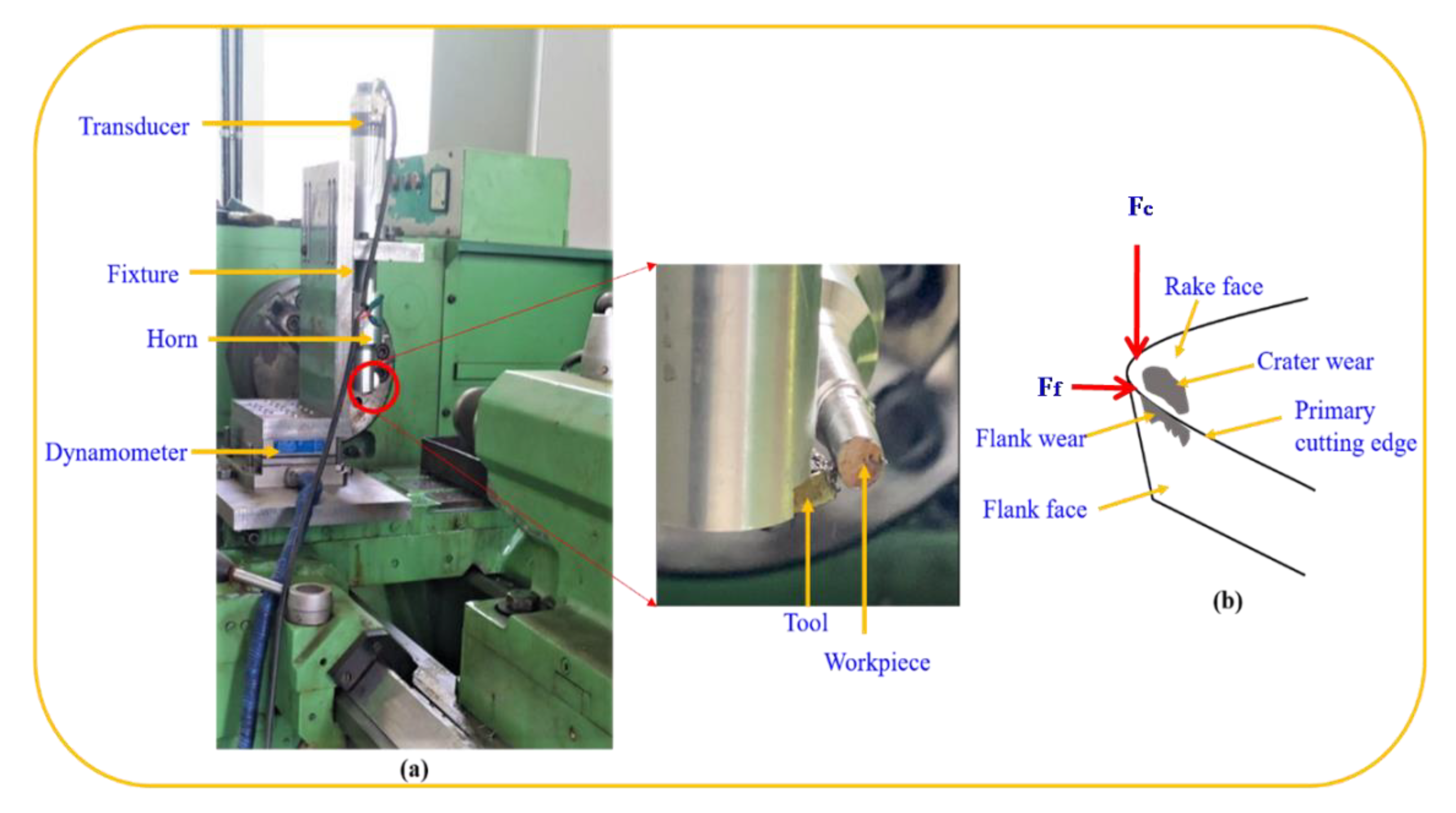
An in-house-developed UAT setup was used to perform the experiments. The setup consists of a fixture, dynamometer, frequency generator, transducer, horn and cutting tool, as shown in Figure 1. The frequency generator generates the electrical signal, which is converted into mechanical vibrations by a piezoelectric transducer. These mechanical signals propagate through the ultrasonic horn to the cutting tool attached at the end. The objective of the ultrasonic horn is to amplify the vibrations to reasonable amplitudes. The horn is a critical component as the vibration transmitted to the tool depends upon a few important design parameters such as the length and diameter of the horn. Any deviation from the recommendations for the parameters leads to the undesirable effect of transverse vibration. As a consequence, the desired effect of longitudinal vibration decreases [26,27]. Here, the material used for the horn is aluminium 7075. The dynamometer placed beneath the fixture measures the forces acting on the tool. The cutting force and feed force acting on the tool are shown in Figure 1.
Nimonic-90 was used as a workpiece material to perform the experiments. Nimonic-90 is a precipitation-hardened nickel-based superalloy with high mechanical properties along with corrosion resistance. It is strengthened by adding titanium and aluminium with 16–20% chromium to enhance the corrosion resistance. It is used for components subjected to high-temperature environments [28]. The chemical composition of the workpiece material is listed in Table 1. Similarly, for performing the turning experiments, chemical vapour deposition (CVD) coated carbide inserts, CNMG 120408 (Make: TaeguTec) with a layer of TiCN, Al2O3 and TiN, were used. The length of the cut used was 30 mm and, for each cut, a fresh cutting edge was used.
The experiments were carried out at constant cutting speed, feed rate, depth of cut and tool geometries, as given in Table 2. The machining was performed using CT and UAT under dry and wet conditions. Flood cooling was used for wet cutting conditions. The length of the cut of 30 mm was considered for each experiment. Each experiment was performed using a new cutting edge and was repeated two more times to reduce the experimental error. The average of three responses was considered for analysis. Here, the full factorial design has been considered for analysis, as a parametric study has not been carried out.
The cutting force was measured in the direction of cutting speed and feed, using a dynamometer. The dynamometer was placed beneath the fixture as shown in Figure 1. The specifications of the dynamometer are given in Table 3. As per the ISO standard ISO 841:2001, the components of the cutting force in the cutting speed and feed direction can be provided by and . The cutting force was measured three times at each input condition, and the average value was considered for analysis. For each setting of parameters, a new cutting edge was used. The cutting force was measured for 65 s and repeated two more times to consider the average responses.
Responses such as tool wear in terms of flank and crater wear were analysed and compared for both the processes. The worn tools were inspected and characterised after each experiment. The flank wear on a flank face and the crater wear on a rake face were analysed, as shown in Figure 1b. The worn tools were etched in dilute hydrochloric acid (HCl) to remove the adhered material for the characterisation. It was shown that HCl-based solution does not affect the WC grains [29]. The flank wear measurement was performed using an optical microscope. A scanning electron microscope was used to examine the analysis and pattern of the tool wear. The description of the scanning electron microscope is given in Table 3. As listed below, the tool wear was decided as per the criteria given by ISO 3685:1993 [30].
- The average width of flank wear (VBb) is larger than 0.3 mm.
- Catastrophic failure of the cutting edge.
3. Results and Discussion
As mentioned in Section 1, nickel-based superalloy exhibits higher tensile strength and shear modulus, poor thermal conductivity, etc. These properties lead to accelerating the tool wear and resulting in high machining forces and power consumption. The machining forces in terms of cutting and feed forces, tool wear behaviour and chip formation are discussed in subsequent subsections.
3.1. Machining Forces
The machining forces, in terms of cutting and feed forces, generated during CT and UAT were measured, and average values are considered for the analysis. The variability is shown by using a normal error bar.
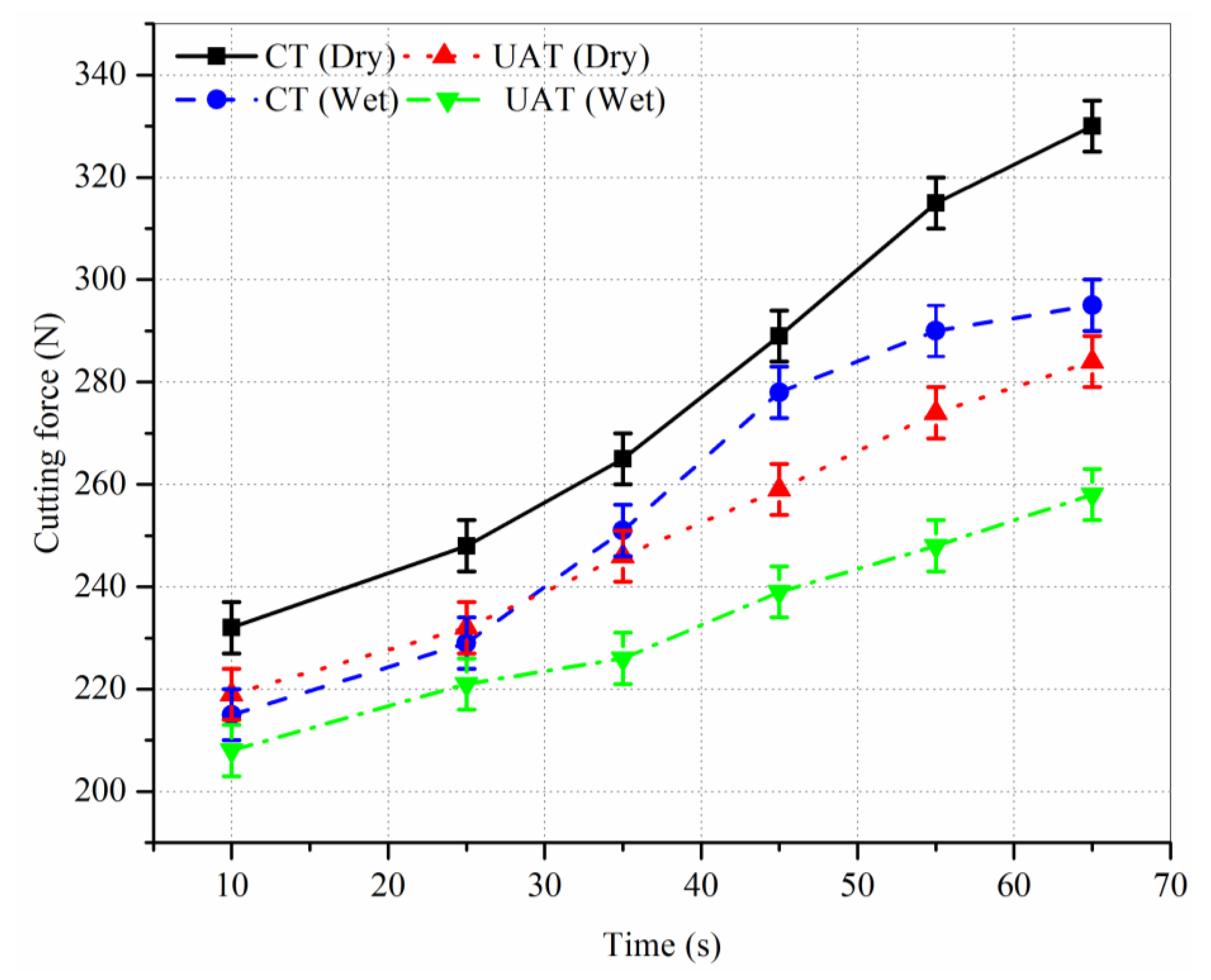
The variation in cutting force with time in CT and UAT under dry and wet conditions is shown in Figure 2. The variation in cutting force is almost similar in all the conditions. The cutting forces progressively rise due to an increase in tool wear. The CT under dry conditions produces the highest cutting force, whereas the UAT under wet conditions produces the lowest cutting force. In the CT, the tool is in continuous contact with the workpiece, which produces a high cutting force. In contrast, the intermittent cutting characteristics reduce the friction between tool and workpiece, which ultimately reduces the cutting force in the UAT [31]. Moreover, in the UAT, during disengagement, the cutting fluid is allowed to penetrate between the tool and the chip, which further reduces the cutting force by reducing friction. The CT under wet conditions also significantly reduces cutting force compared to that in CT under dry conditions. The approximate reductions in the cutting force in UAT under dry conditions are 20%, 9% and 6% compared to CT under dry, CT under wet, and UAT under dry conditions, respectively.
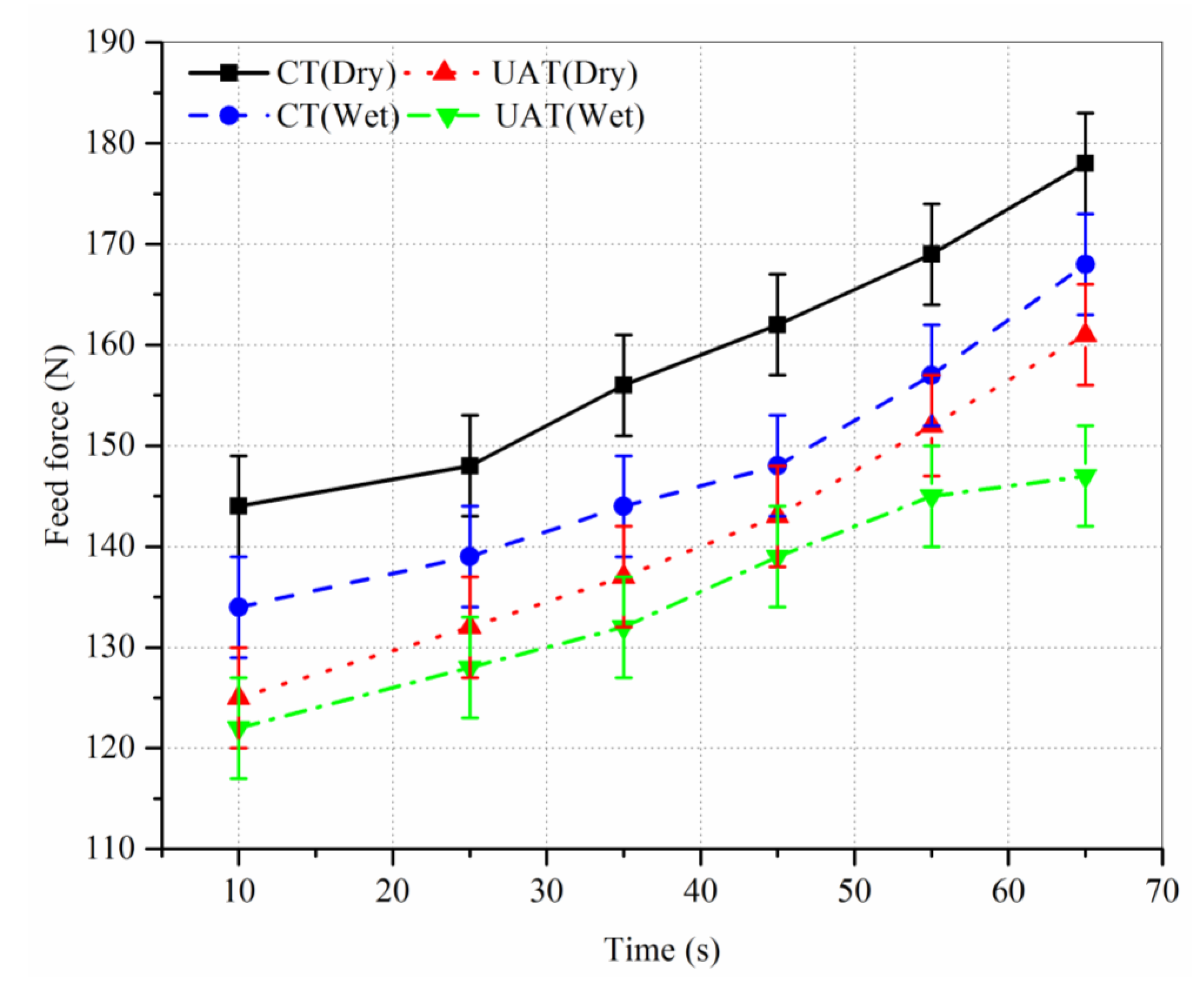
A variation in feed force with time in CT and UAT under dry and wet conditions is shown in Figure 3. The variation in cutting force is almost similar in all the conditions. The feed forces progressively rise due to an increase in tool wear. The feed force obtained in CT and UAT under dry and wet conditions is shown in Figure 3. The feed force obtained in the UAT under wet conditions is the lowest amongst both conditions. The CT does not show a significant difference in feed force under dry and wet conditions; however, the difference is noticeable in the UAT for both conditions. The UAT allows the cutting fluid to penetrate during the disengagement period, which reduces contact between tool and workpiece and ultimately reduces the feed force [32]. The approximate reductions in the feed force in UAT under dry conditions are 27%, 17%, and 13% compared to CT under dry, CT under wet and UAT under dry conditions, respectively.
3.2. Tool Wear
In order to analyse the characteristics and mechanisms of tool wear in UAT and CT, optical and scanning electron microscopy were used. The results obtained for flank and crater wear are discussed subsequently.
3.2.1. Flank Wear
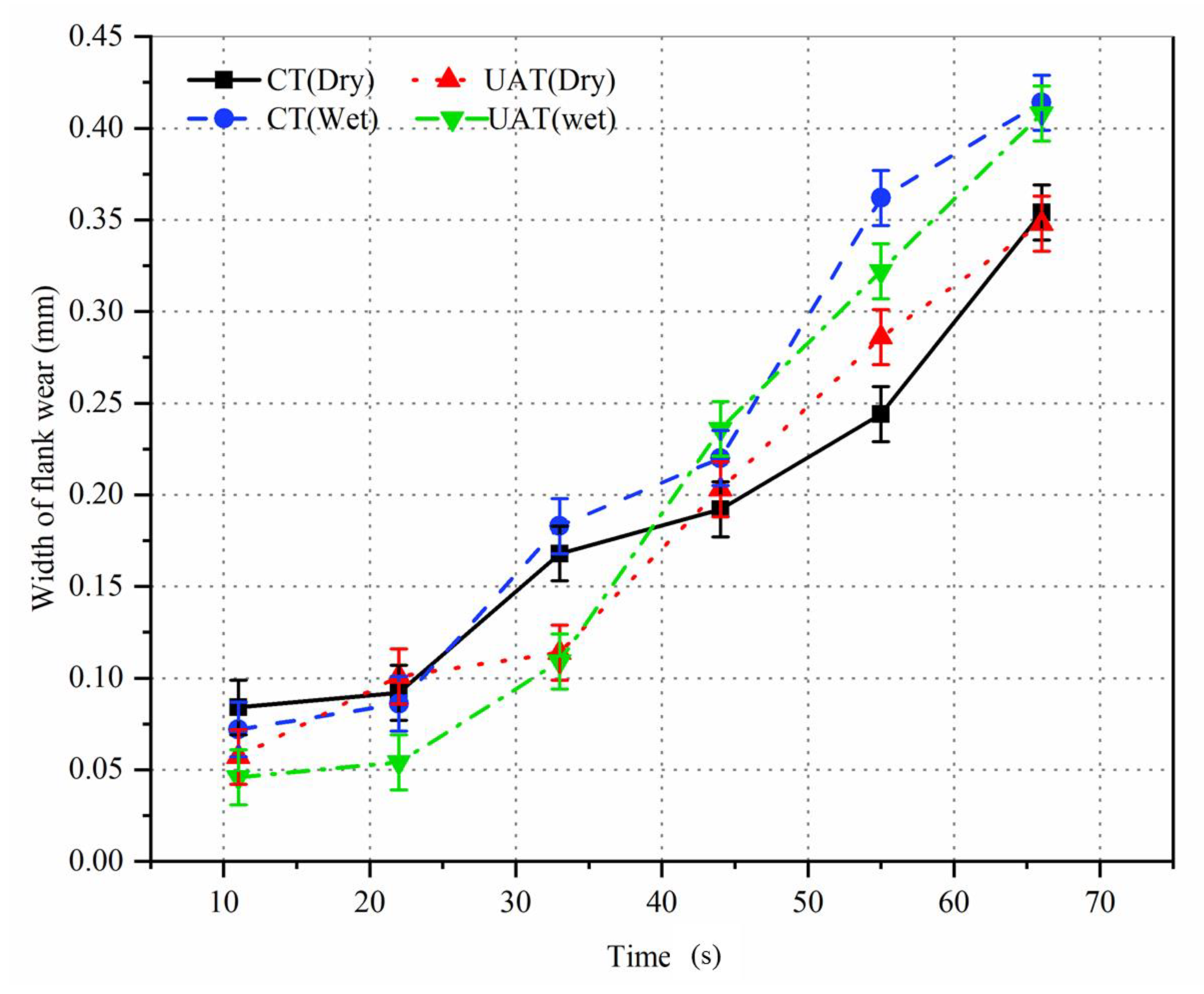
The variation in the width of flank wear (VBb) with machining time for UAT and CT under dry and wet conditions is shown in Figure 4. The poor thermal conductivity of Nimonic-90 increases the shear stress imposed on the tool, and ultimately, tool wear increases rapidly [33]. The trend is almost similar for both cutting conditions. Initially, the difference between VBb in UAT and CT is not significant. At the end of machining, CT and UAT under dry conditions show a lower value of VBb than in wet conditions in both the processes. This could be due to higher strain hardening during the machining of Nimonic-90 under wet conditions, increasing the flank wear and reducing the tool life [34]. In the UAT, the intermittent contact between tool and workpiece reduces the tool–workpiece contact ratio and decreases tool wear. However, the UAT under wet conditions shows a nearly similar value of VBb to that in CT under wet conditions. The CT and UAT under dry conditions show similar results at the end of machining. However, the CT under dry conditions shows better results between durations of 45 s and 65 s. This can be attributed to built-up edge formation in the CT under dry conditions, as shown in Figure 5 and Figure 6, which may reduce the contact between the tool and the workpiece and reduce the VBb [35]. At the end of machining, the size of the built-up edge may reduce, increasing the contact between tool and workpiece, which increases the VBb. An approximate reduction in the VBb is 20% in the UAT and CT under dry conditions compared to UAT and CT under wet conditions at the end of machining. In other words, the VBb can be reduced by using dry conditions in both the processes.
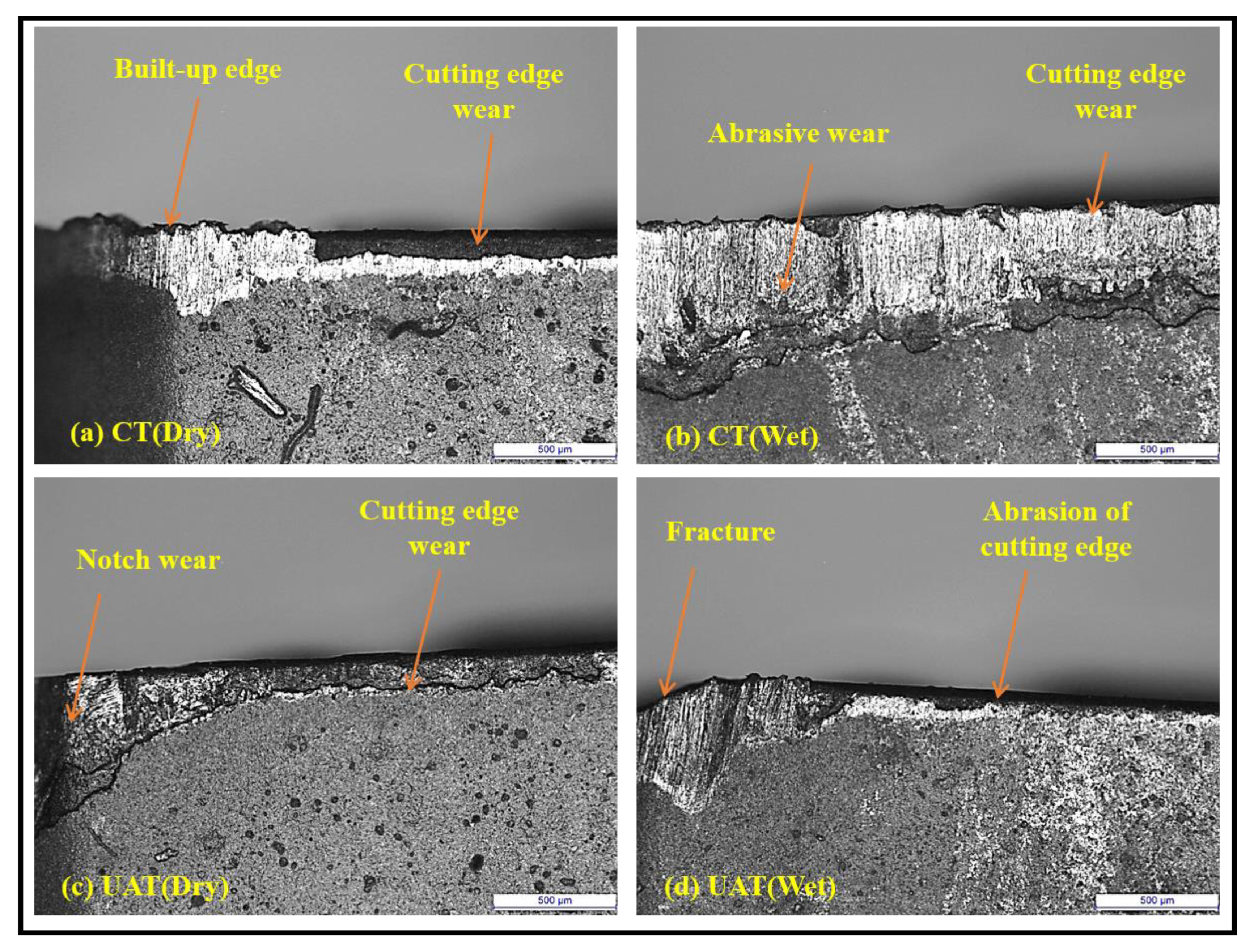
Characteristics of the flank wear in UAT and CT under dry and wet conditions, observed by optical microscope, are shown in Figure 5. A built-up edge is observed near the tool nose in the CT under dry conditions, as shown in Figure 5a. The built-up edge is formed due to the chemical affinity and ductility of Nimonic-90. A similar observation has been made by Chetan et al. [36] for machining Nimonic-90 under dry conditions. The wear of the main cutting edge is also observed under the same condition. This may be due to friction between the tool and the chip, which causes the abrasion of the main cutting edge [24]. The CT under wet conditions shows more abrasion on the flank face and the main cutting edge, as shown in Figure 5b. The width of flank wear significantly increases under wet conditions compared to dry conditions. It can be said that the conventional cooling or wet conditions accelerate the tool flank wear. The coolant suppresses the built-up edge formation and increases the contact between tool and chip, increasing the abrasion at the flank face and main cutting edge in wet conditions [37]. The UAT significantly reduces the width of flank wear under dry conditions compared to CT, as shown in Figure 5c. The notch wear at the tool nose is prominent in the UAT, which is not obvious in the CT. Since the cutting action is intermittent in the UAT, the contact between tool and workpiece reduces, decreasing the abrasion on the flank face. However, due to intermittent cutting action, the load on the tool nose rises, increasing the possibility of notch wear at the tool nose. The UAT under wet conditions reduces the flank wear compared to CT under wet conditions, as shown in Figure 5d. A similar observation of a reduction in flank wear in UAT of AISI 4140 was also observed by Lotfi et al. [24]. Due to the high stresses imposed by Nimonic-90, cyclic motion of the tool, and thermal stresses due to wet conditions, the fracture is obvious in the UAT. It can be said that conventional wet cooling increases the tool flank wear in the machining of Nimonic-90.
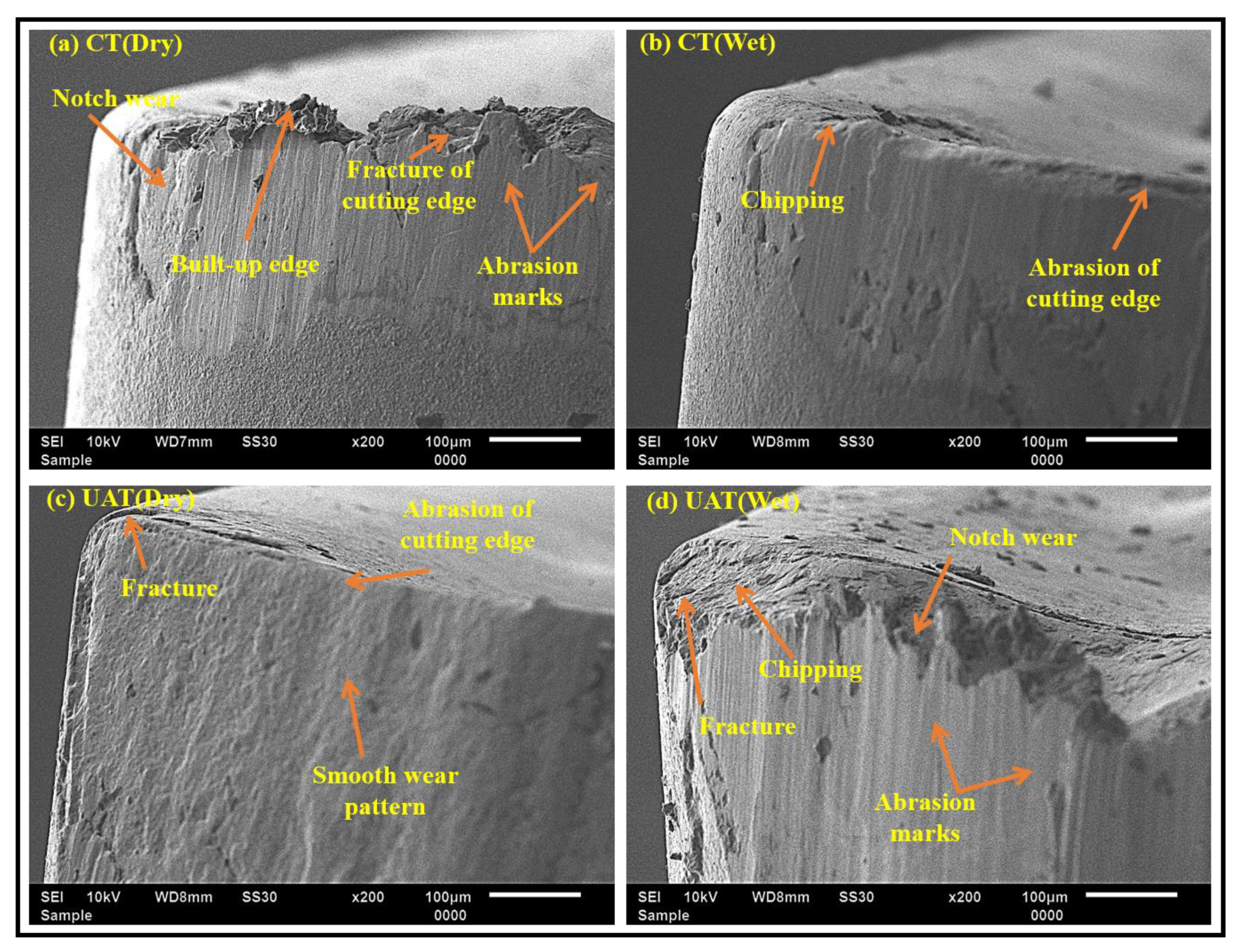
In order to understand the behaviour of tool flank wear, scanning electron microscopy (SEM, manufacturer, Dartford, UK) was used. The results obtained for the flank face are shown in Figure 6. Initially, the CT shows better results compared to UAT under dry conditions, as shown in Figure 4. At the end of machining, it shows a significant wear on the flank face, as shown in Figure 6a. As explained earlier, the built-up edge is prominent in the machining of Nimonic-90. When the built-up edge breaks, it takes away a small particle of tool material, which leads to the fracture of the cutting edge. This may result in an increment of flank wear as shown in Figure 4. Moreover, the fracture and notch wear are observed on the flank face in the same condition. The notch wear is a V-shaped groove in a depth-of-cut direction during the machining of nickel-based superalloy [38]. Another wear mechanism observed is abrasion on the flank face. Hard carbide particles enter the tool–workpiece interface leading to abrasion. The CT under wet conditions does not show significant wear on the flank face, as shown in Figure 6b. Small chipping is noted at the cutting edge due to the breakage of the built-up edge. In the wet conditions, the abrasion on the flank face is not severe, which is obvious in dry conditions. Small abrasion on the cutting edge is detected due to insufficient cooling near the edge [39]. In UAT under dry conditions, the fracture at the nose and abrasion at the cutting edge are observed, as shown in Figure 6c. The wear is not as severe as in CT under dry conditions. The fracture is mainly due to the intermittent cutting action of the tool, and the hardness of Nimonic-90. As the tool repeatedly separates from the workpiece, the hard carbide particles entering into the tool–workpiece interface are reduced, thus the abrasion marks are not noted. However, the situation is quite the opposite in the UAT under wet conditions, as shown in Figure 6d. The use of a coolant enhances the tool wear in the UAT. The fracture and notch wear at the tool nose and chipping at the cutting edge are observed. These may be attributed to the work hardening of Nimonic-90 and fatigue loading due to ultrasonic vibration, enhancing the wear even in wet conditions [26]. It can be said that the wet conditions accelerate the tool wear and consequently reduce the tool life in the CT and UAT processes.
3.2.2. Crater Wear
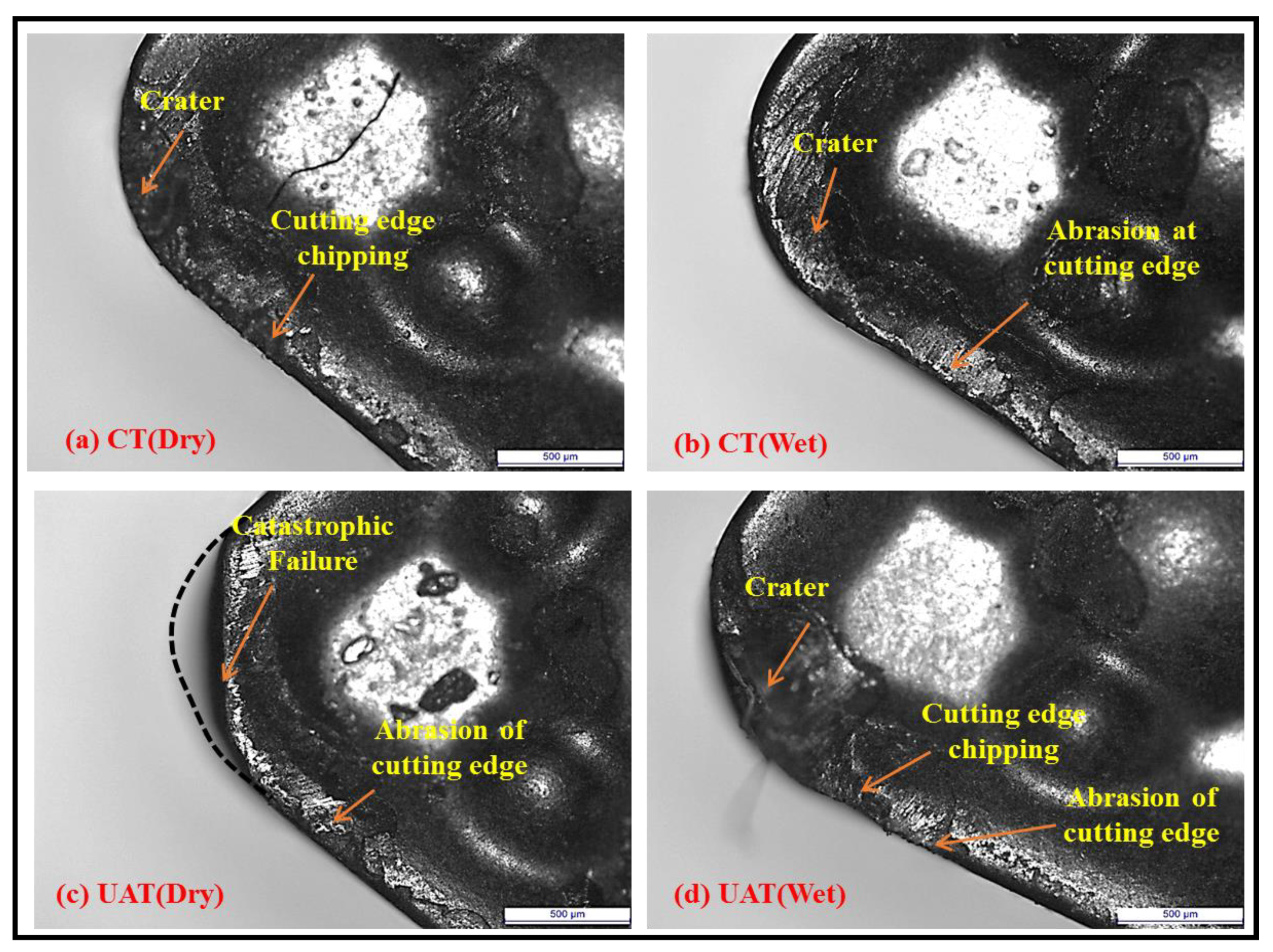
Characteristics of the wear on the rake face in UAT and CT under dry and wet conditions, observed by optical microscope, are shown in Figure 7. The crater is observed in the CT under dry conditions, as shown in Figure 7a. The chips flow over the rake face, which is mainly responsible for the crater formation. Nickel-based superalloy induces higher stresses than steel, brass, copper, lead etc. during machining. These stresses are in the range 900–1000 MPa for nickel-based superalloy, whereas they are 500–600 MPa for titanium, 700–800 MPa for stainless steel, etc. [40]. In the machining of Nimonic-90, the pressure and stresses near the tool edge increase the friction between tool and chip, which causes crater wear. The edge chipping is also observed in the same condition. This may be attributed to the high temperature generation at the cutting edge [36]. Figure 7b shows that the CT under wet conditions displays a crater formation, but it is not as prominent as in dry conditions. The wet conditions reduce the heat generation at the cutting edge, decreasing the tendency of the crater. In this condition, the abrasion is also observed at the cutting edge due to friction between tool and chip. The UAT under dry conditions shows a catastrophic failure of the tool nose, as shown in Figure 7c. The dotted line indicates the tool nose before machining. The cyclic action of the tool causes fatigue loading on the tool, and the brittleness of tungsten carbide, leading to the failure of the tool nose. In the same condition, a small abrasion is also observed at the cutting edge. The UAT under wet conditions suppresses the failure of the tool nose, as shown in Figure 7d. However, the formation of the crater and the chipping and a small abrasion of the cutting edge are observed in the same condition. The crater formation is due to high temperature and pressure near the cutting edge.
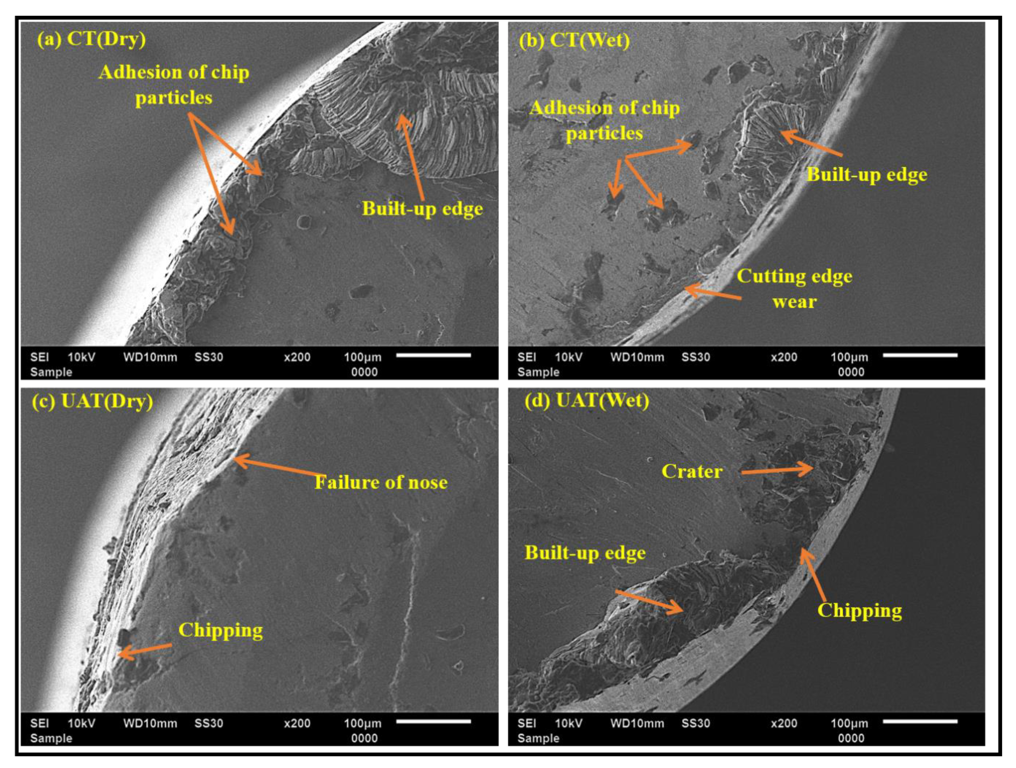
In order to understand the behaviour of wear on the rake face, scanning electron microscopy (SEM) was performed. The results obtained are shown in Figure 8. The CT under dry conditions shows adhesion of the built-up edge and small chip particles on the rake face, as shown in Figure 8a. The adhesion is attributed to sticking chips with the tool due to a high pressure near the cutting edge [41]. In the wet conditions, a small built-up edge and microparticles of chips adhere near the cutting edge. The use of coolant suppresses the adhesion of the built-up edge on the rake face. However, insufficient penetration of the coolant and high stresses near the cutting edge lead to the adhesion and wear of the cutting edge. The research group of L.N.L. d.L [38,42] promoted discussion of crater wear results and gave some ideas about the performance of coolant on superalloys. During the machining of the superalloy under wet conditions, it was found that strong adhesion on the rake face leads to a nose breakage on the tooltip. In the case of the UAT, failure of the tool nose and chipping at the cutting edge are observed, as shown in Figure 8c. This is explained by the phenomenon that in the machining of Nimonic-90, the temperature and pressure are very high near the cutting edge, increasing the plastic deformation of the tool near the nose in the dry condions [36]. Furthermore, a cyclic motion of the tool in the UAT enforces the plastic deformation and ultimately leads to failure. The fracture at the nose is suppressed by using the coolant in the UAT, as shown in Figure 8d. However, a small crater, built-up edge and chipping of the cutting edge are observed. The crater is mainly due to the chemical affinity of Nimonic-90 and tools [34,35]. A high temperature near the cutting edge imposes the welding between chip and tool even in the UAT, leading to the built-up edge and chipping adhesion.
3.3. Chip Analysis
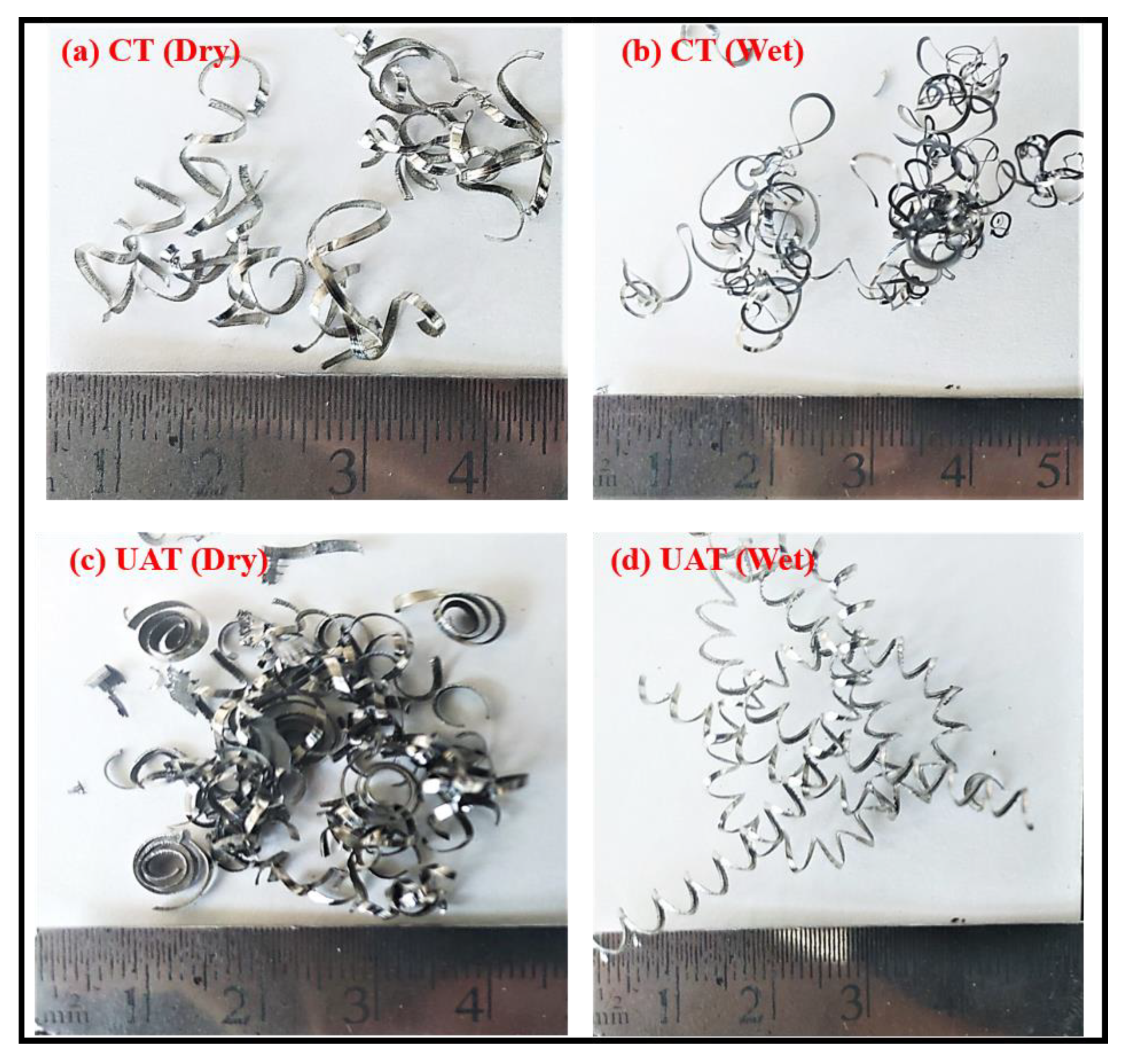
The geometry and morphology of chips formed during machining are an integral part of the machinability of workpiece material. The chips are variable in shape and size in machining processes. The formation of chips comprises a shearing of the workpiece in the primary deformation zone [40]. The chips produced during UAT and CT under dry and wet conditions are shown in Figure 9. The chips formed under dry conditions are thicker, whereas they are thinner under the wet conditions in both the processes. The coolant reduces the chip thickness by reducing friction [26]. The CT under both the conditions produces chips with a larger distortion and curling radius due to continuous contact with the tool and workpiece [43]. However, the UAT under both conditions produces chips with lower distortion and curling radius. This may be attributed to the aerodynamic lubricating action that takes place in UAT, which reduces the distortion and thickness. The chips formed during UAT under dry conditions show a better chip breakability. This is attributed to the higher value of shear angle, reducing chip thickness and increasing the chip breakability. The UAT under wet conditions produces continuous chips, as shown in Figure 9d. This may be due to the cooling action, which restricts the crack propagation on the chip and produces a continuous chip.
4. Conclusions
CT and UAT of Nimonic-90 under dry and wet conditions were performed to analyse cutting force tool wear behaviour and chips. The behaviour of tool flank and crater wear was analysed microscopically. UAT on the mentioned conditions has been explored less in the past; therefore, given the importance of UAT, a comprehensive study has been presented. The following conclusions can be made:
- UAT under wet conditions shows approximate reductions in cutting force of 20%, 9% and 6% compared to CT under dry, CT under wet, and UAT under dry conditions, respectively.
- UAT under wet conditions shows approximate reductions in feed force of 27%, 17%, and 13% compared to CT under dry, CT under wet and UAT under dry conditions, respectively.
- At the end of machining, CT and UAT under dry conditions show an approximate reduction of 20% in the width of flank wear compared to CT and UAT under wet conditions.
- The primary wear mechanisms are abrasion, chipping, notch wear and adhesion of the built-up edge in both processes. However, by using a coolant, the formation of the built-up edge can be reduced.
- The chips formed during UAT are thinner, smoother and shorter than those formed during CT, leading to improved machinability during the UAT process.
Author Contributions
Conceptualization, J.A.; methodology, J.A., C.K.N., N.K.; software, J.A.; validation, J.A., formal analysis, J.A.; investigation, J.A.; resources, N.K., L.N.L.d.L.; data curation, J.A., C.K.N., N.K.; writing—original draft preparation, J.A.; writing—review and editing, C.K.N., N.K., L.N.L.d.L.; visualization, J.A., C.K.N., N.K., L.N.L.d.L. All authors have read and agreed to the published version of the manuscript.
Funding
This research received no external funding.
Institutional Review Board Statement
Not applicable.
Informed Consent Statement
Not applicable.
Data Availability Statement
Not applicable.
Acknowledgments
The executed work is as per the MOU signed between the Advanced Manufacturing Laboratory (IITRAM, India) and the Advanced Manufacturing Research Group (UPV/EHU, Bilbao, Spain), and the research collaboration between the Advanced Manufacturing Laboratory (IITRAM, India) and the Micromachining and Monitoring Lab (IIT Ropar, India). The authors are thankful to the ICFAMMT 2022 (IITRAM, India) for facilitating submission in peer-reviewed journals.
Conflicts of Interest
The authors declare no conflict of interest.
Nomenclature
| a | Depth of cut (mm) |
| Feed rate (mm/rev) | |
| Cutting speed (m/min) | |
| Cutting force | |
| Feed force | |
| VBb | Width of flank wear |
| CT | Conventional turning |
| CM | Conventional milling |
| CVD | Chemical vapour deposition |
| PCD | Polycrystalline diamond |
| SEM | Scanning electron microscopy |
| UAD | Ultrasonic assisted drilling |
| UAM | Ultrasonic assisted milling |
| UAT | Ultrasonic assisted turning |
References
- Choudhury, I.A.; El-Baradie, M.A. Machinability of nickel-base super alloys: A general review. J. Mater. Process Technol. 1998, 77, 278–284. [Google Scholar] [CrossRef]
- Khanna, N.; Airao, J.; Gupta, M.K.; Song, Q.; Liu, Z.; Mial, M.; Maruda, R.; Krolczyk, G. Optimization of power consumption as-sociated with surface roughness in ultrasonic assisted turning ofNimonic-90 using hybrid particle swarm-simplex method. Materials 2019, 12, 3418. [Google Scholar] [CrossRef] [Green Version]
- Choi, Y.H.; Lee, C.M. A study on the machining characteristics of AISI 1045 steel and inconel 718with circular cone shape in induction assisted machining. J. Manuf. Process. 2018, 34, 463–476. [Google Scholar] [CrossRef]
- Germain, G.; DalSanto, P.; Lebrun, J.L. Comprehension of chip formation in laser assisted machining. Int. J. Mach.Tools Manuf. 2011, 51, 230–238. [Google Scholar] [CrossRef] [Green Version]
- Parida, A.K.; Maity, K. Study of machinability in heat-assisted machining of nickel-base alloy. Measurement 2021, 170, 108682. [Google Scholar] [CrossRef]
- Gupta, M.K.; Mia, M.; Pruncu, C.I.; Kaplonek, W.; Nadolny, K.; Patra, K.; Mikolajczyk, T.; Pimenov, D.Y.; Sarikaya, M.; Sharma, V.S. Parametric optimisation and process capability analysis for machining of nickel-based superalloy. Int. J. Adv. Manuf. Technol. 2019, 102, 3995–4009. [Google Scholar] [CrossRef] [Green Version]
- Gupta, M.K.; Song, Q.; Liu, Z.; Sarikaya, M.; Jamil, M.; Mia, M.; Singla, A.K.; Khan, A.M.; Khanna, N.; Pimenov, D.Y. Environment and economic burden of sustainable cooling/lubrication methods in machining of Inconel-800. J. Clean. Prod. 2021, 287, 125074. [Google Scholar] [CrossRef]
- Muhammad, R.; Hussain, M.S.; Maurotto, A.; Siemers, C.; Roy, A.; Silberschmidt, V.V. Analysis of a free machining α+β titanium alloy using conventional and ultrasonically assisted turning. J. Mater. Process. Technol. 2014, 214, 906–915. [Google Scholar] [CrossRef] [Green Version]
- Khanna, N.; Shah, P.; Agrawal, C.; Pusavec, F.; Hegab, H. Inconel 718 machining performance evaluation using indigenously developed hybrid machining facilities: Experimental investigation and sustainability assessment. Int. J. Adv. Manuf. Technol. 2020, 106, 4987–4999. [Google Scholar] [CrossRef]
- Puga, H.; Grilo, J.; Carneiro, V.H. Ultrasonic Assisted Turning of Al alloys: Influence of Material Processing to Improve Surface Roughness. Surfaces 2019, 2, 24. [Google Scholar] [CrossRef] [Green Version]
- Maroju, N.K.; Pasam, V.K. FE Modeling and Experimental Analysis of Residual Stresses in Vibration Assisted Turning of Ti6Al4V. Int. J. Precis. Eng. Manuf. 2019, 20, 417–425. [Google Scholar] [CrossRef]
- Verma, G.C.; Pandey, P.M. Machining forces in ultrasonic-vibration assisted end milling. Ultrasonics 2019, 94, 350–363. [Google Scholar] [CrossRef]
- Zhao, C.; Wang, X.; Zhao, B.; Jiao, F. Microstructure of High-Performance Aluminum Alloy Surface Processed by the Single-Excitation Same-Frequency Longitudinal–Torsional Coupled Ultrasonic Vibration Milling. Materials 2018, 11, 1975. [Google Scholar] [CrossRef] [PubMed] [Green Version]
- Niu, Y.; Jiao, F.; Zhao, B.; Gao, G. Investigation of Cutting Force in Longitudinal-Torsional Ultrasonic-Assisted Milling of Ti-6Al-4V. Materials 2019, 12, 1955. [Google Scholar] [CrossRef] [PubMed] [Green Version]
- Liu, Q.; Xu, J.; Yu, H. Experimental study of tool wear and its effects on cutting process of ultrasonic-assisted milling of Ti6Al4V. Int. J. Adv. Manuf. Technol. 2020, 108, 2917–2928. [Google Scholar] [CrossRef]
- Suárez, A.; Veiga, F.; de Lacalle, L.N.L.; Polvorosa, R.; Lutze, S.; Wretland, A. Effects of Ultrasonics-Assisted Face Milling on Surface Integrity and Fatigue Life of Ni-Alloy 718. J. Mater. Eng. Perform. 2016, 25, 5076–5086. [Google Scholar] [CrossRef]
- Paktinat, H.; Amini, S. Ultrasonic assistance in drilling: FEM analysis and experimental approaches. Int. J. Adv. Manuf. Technol. 2017, 92, 2653–2665. [Google Scholar] [CrossRef]
- Paktinat, H.; Amini, S. Experiments and Finite Element Simulation of Ultrasonic Assisted Drilling. ASME J. Manuf. Sci. Eng. 2018, 140, 101002. [Google Scholar] [CrossRef]
- Chu, N.H.; Nguyen, V.D.; Ngo, Q.H. Machinability enhancements of ultrasonic-assisted deep drilling of aluminum alloys. Mach. Sci. Technol. 2020, 24, 112–135. [Google Scholar] [CrossRef]
- Pujana, J.; Rivero, A.; Celaya, A.; López de Lacalle, L.N. Analysis of ultrasonic-assisted drilling of Ti6Al4V. Int. J. Mach. Tools Manuf. 2009, 49, 500–508. [Google Scholar] [CrossRef]
- Dong, G.; Zhang, H.; Zhou, M.; Zhang, Y. Experimental Investigation on Ultrasonic Vibration-Assisted Turning of SiCp/Al Composites. Mater. Manuf. Process. 2013, 28, 999–1002. [Google Scholar] [CrossRef]
- Amini, S.; Khosrojerdi, M.R.; Nosouhi, R.; Behbahani, S. An Experimental Investigation on the Machinability of Al2O3 in Vibration-Assisted Turning Using PCD Tool. Mater. Manuf. Process. 2014, 29, 331–336. [Google Scholar] [CrossRef]
- Zou, L.; Huang, Y.; Zhou, M.; Duan, L. Investigation on diamond tool wear in ultrasonic vibration-assisted turning die steels. Mater. Manuf. Process. 2017, 32, 1505–1511. [Google Scholar] [CrossRef]
- Lotfi, M.; Amini, S.; Aghaei, M. Tool Wear Prediction and Surface Improvement in Vibration Cutting. Tribol. Trans. 2018, 61, 414–423. [Google Scholar] [CrossRef]
- Tsai, M.Y.; Chang, C.T.; Ho, J.K. The Machining of Hard Mold Steel by Ultrasonic Assisted End Milling. Appl. Sci. 2016, 6, 373. [Google Scholar] [CrossRef] [Green Version]
- Airao, J.; Khanna, N.; Roy, A.; Hegab, H. Comprehensive experimental analysis and sustainability assessment of machining Nimonic 90 using ultrasonic-assisted turning facility. Int. J. Adv. Manuf. Technol. 2020, 109, 1447–1462. [Google Scholar] [CrossRef]
- Celaya, A.; López de Lacalle, L.N.; Campa, F.J.; Lamikiz, A. Ultrasonic Assisted Turning of mild steels. Int. J. Mater. Prod. Technol. 2010, 37, 60. [Google Scholar] [CrossRef]
- Helmi. A.Y. Machining of Stainless Steels and Super Alloys; John Wiley & Sons: Chichester, UK, 2015. [Google Scholar]
- Hoier, P.; Malakizadi, A.; Friebe, S.; Klement, U.; Krajnik, P. Microstructural variations in 316l austenitic stainless steel and their influence on tool wear in machining. Wear 2019, 428, 315–327. [Google Scholar] [CrossRef]
- Kaynak, Y.; Lu, T.; Jawahir, I.S. Cryogenic machining-induced surface integrity: A review and comparison with Dry, MQL, and flood-cooled machining. Mach. Sci. Technol. 2014, 18, 149–198. [Google Scholar] [CrossRef]
- Babitsky, V.; Mitrofanov, A.V.; Silberschmidt, V.V. Ultrasonically assisted turning of aviation materials: Simulations and experimental study. Ultrasonics 2004, 42, 81–86. [Google Scholar] [CrossRef] [PubMed]
- Bai, W.; Bisht, A.; Roy, A.; Suwas, S.; Sun, R.; Silberschmidt, S. Improvements of machinability of aerospace-grade Inconel alloys with ultrasonically assisted hybrid machining. Int. J. Adv. Manuf. Technol. 2019, 101, 1143–1156. [Google Scholar] [CrossRef] [Green Version]
- Ross, K.N.S.; Manimaran, G.; Anwar, S.; Rahman, M.A.; Korkmaz, M.E.; Gupta, M.K.; Alfaify, A.; Mia, M. Investigation of surface modification and tool wear on milling Nimonic 80A under hybrid lubrication. Tribol. Int. 2021, 155, 106762. [Google Scholar]
- Patel, T.; Khanna, N.; Yadav, S.; Shah, P.; Sarikaya, M.; Singh, D.; Gupta, M.K.; Kotkunde, N. Machinability analysis of nickel-based superalloy Nimonic 90: A comparison between wet and LCO2 as a cryogenic coolant. Int. J. Adv. Manuf. Technol. 2021, 113, 3613–3628. [Google Scholar]
- Muhammad, A.; Gupta, M.K.; Mikołajczyk, T.; Pimenov, D.Y.; Giasin, K. Effect of Tool Coating and Cutting Parameters on Surface Roughness and Burr Formation during Micromilling of Inconel 718. Metals 2021, 11, 167. [Google Scholar] [CrossRef]
- Chetan, G.S.; Rao, P.V. Performance evaluation of deep cryogenic processed carbide inserts during dry turning of Nimonic 90 aerospace grade alloy. Tribol. Int. 2017, 115, 397–408. [Google Scholar] [CrossRef]
- Ji, H.; Gupta, M.K.; Song, Q.; Cai, W.; Zheng, T.; Zhao, Y.; Liu, Z.; Pimenov, D.Y. Microstructure and machinability evaluation in micro milling of selective laser melted Inconel 718 alloy. J. Mater. Res. Technol. 2021, 14, 348–362. [Google Scholar] [CrossRef]
- Polvorosa, R.; Suárez, A.; López de Lacalle, L.N.; Cerrillo, I.; Wretland, A.; Veiga, F. Tool wear on nickel alloys with different coolant pressures: Comparison of Alloy 718 and Waspaloy. J. Manuf. Process 2017, 26, b44–b56. [Google Scholar] [CrossRef]
- Zhu, D.; Zhang, X.; Ding, H. Tool wear characteristics in machining of nickel-based superalloys. Int. J. Mach. Tools Manuf. 2013, 64, 60–77. [Google Scholar] [CrossRef]
- Trent, E.M.; Wright, P.K. Metal Cutting. Butterworth-Heinemann; Elsevier: Amsterdam, The Netherlands, 2000. [Google Scholar]
- Khanna, N.; Agrawal, C.; Dogra, M.; Pruncu, C.I. Evaluation of tool wear, energy consumption, and surface roughness during turning of inconel 718 using sustainable machining technique. J. Mater. Res. Technol. 2020, 9, 5794–5804. [Google Scholar] [CrossRef]
- Fernández-Valdivielso, A.; López de Lacalle, L.N.; Urbikain, G.; Rodríguez, A. Detecting the key geometrical features and grades of carbide inserts for the turning of nickel-based alloys concerning surface integrity. Proc. Inst. Mech. Eng. Part C J. Mechanical. Eng. Sci. 2015, 230, 3725–3742. [Google Scholar] [CrossRef]
- Celaya, A.; López de Lacalle, L.N.; Campa, F.J.; Lamikiz, A. Application of ultrasonics as assistance inmachining operations. In Ultrasonics: Theory, Techniques and Practical Applications; Ayabito, H., Katsukawa, M., Eds.; Nova Science Publishers: New York, NY, USA, 2013; pp. 159–172. ISBN 978-1-62257-685-2. [Google Scholar]
Figure 1.
(a) In-house-developed UAT setup and (b) flank and crater wear measurement.

Figure 2.
Variation in cutting force with time in CT and UAT under dry and wet conditions (= 50 m/min, = 0.2 mm/rev, = 0.4 mm).
Figure 2.
Variation in cutting force with time in CT and UAT under dry and wet conditions (= 50 m/min, = 0.2 mm/rev, = 0.4 mm).

Figure 3.
Variation in feed force with time in CT and UAT under dry and wet conditions (= 50 m/min, = 0.2 mm/rev, = 0.4 mm).
Figure 3.
Variation in feed force with time in CT and UAT under dry and wet conditions (= 50 m/min, = 0.2 mm/rev, = 0.4 mm).

Figure 4.
Variation in flank wear with machining time in CT and UAT under dry and wet conditions (= 50 m/min, = 0.2 mm/rev, = 0.4 mm).
Figure 4.
Variation in flank wear with machining time in CT and UAT under dry and wet conditions (= 50 m/min, = 0.2 mm/rev, = 0.4 mm).

Figure 5.
Characteristics of flank wear observed by optical microscope (= 50 m/min, = 0.2 mm/rev, = 0.4 mm).
Figure 5.
Characteristics of flank wear observed by optical microscope (= 50 m/min, = 0.2 mm/rev, = 0.4 mm).

Figure 6.
The behaviour of flank wear observed by scanning electron microscope (= 50 m/min, = 0.2 mm/rev, = 0.4 mm).
Figure 6.
The behaviour of flank wear observed by scanning electron microscope (= 50 m/min, = 0.2 mm/rev, = 0.4 mm).

Figure 7.
Characteristics of crater wear observed by optical microscope (= 50 m/min, = 0.2 mm/rev, = 0.4 mm).
Figure 7.
Characteristics of crater wear observed by optical microscope (= 50 m/min, = 0.2 mm/rev, = 0.4 mm).

Figure 8.
The behaviour of wear on the rake face observed by scanning electron microscope (= 50 m/min, = 0.2 mm/rev, = 0.4 mm).
Figure 8.
The behaviour of wear on the rake face observed by scanning electron microscope (= 50 m/min, = 0.2 mm/rev, = 0.4 mm).

Figure 9.
Chips formed during CT and UAT and dry and wet conditions (= 50 m/min, = 0.2 mm/rev, = 0.4 mm).
Figure 9.
Chips formed during CT and UAT and dry and wet conditions (= 50 m/min, = 0.2 mm/rev, = 0.4 mm).


Table 1.
Chemical composition of Nimonic-90 [26].
Table 1.
Chemical composition of Nimonic-90 [26].
| Element | C | Si | Mg | Cr | Ni | Ti | Al | Co | Fe |
|---|---|---|---|---|---|---|---|---|---|
| % Weight | 0.08 | 0.13 | 0.018 | 18.1 | Balance | 2.4 | 1.09 | 18.5 | 0.82 |
Table 2.
Input process parameters for experimentation.
| Parameter | Range | |||
|---|---|---|---|---|
| Workpiece | Nimonic-90 cylindrical rod with a diameter of 40 mm | |||
| Tool | WC with CVD coating of TiCN-Al2O3-TiN | |||
| Coating thickness (µm) | 1–4 microns for each layer of coating | |||
| Rake angle (°) | 5 | |||
| Nose radius (mm) | 0.8 | |||
| Machine tool | Conventional lathe (HMT NH 22) | |||
| Specification | Power of 11 kW, maximum spindle speed 2040 rpm | |||
| Cutting speed (m/min) | 50 | |||
| Feed rate (mm/rev) | 0.2 | |||
| Depth of cut (mm) | 0.4 | |||
| Cutting time | 65 s at each input condition | |||
| Cutting action | Conventional turning | Ultrasonic assisted turning | ||
| Frequency (Hz) | 0 | 20,000 | ||
| Amplitude (µm) | 0 | 10 | ||
| Cutting condition | Dry | Wet | Dry | Wet |
| Cooling system | Conventional flood cooling (SAE oil diluted in water) | |||
Table 3.
Specifications of measuring instruments.
| Dynamometer for Force Measurement | |
| Manufacturer | KISTLER |
| Series | 9257 multicomponent |
| Measuring range | −5 kN to 5 kN |
| Natural frequency | 2–3 kHz |
| Scanning Electron Microscope to Characterise Tool Wear | |
| Manufacturer | JEOL |
| Series | JSM 6610LV |
| Resolution mode | 3.0 nm (30 kV), 8 nm (3 kV), 15 nm (1 kV) |
| Magnification | 300,000 |
| Accelarating Voltage | 0.3–30 kV |
Publisher’s Note: MDPI stays neutral with regard to jurisdictional claims in published maps and institutional affiliations. |
© 2021 by the authors. Licensee MDPI, Basel, Switzerland. This article is an open access article distributed under the terms and conditions of the Creative Commons Attribution (CC BY) license (https://creativecommons.org/licenses/by/4.0/).
Share and Cite
MDPI and ACS Style
Airao, J.; Nirala, C.K.; Lacalle, L.N.L.d.; Khanna, N. Tool Wear Analysis during Ultrasonic Assisted Turning of Nimonic-90 under Dry and Wet Conditions. Metals 2021, 11, 1253. https://0-doi-org.brum.beds.ac.uk/10.3390/met11081253
AMA Style
Airao J, Nirala CK, Lacalle LNLd, Khanna N. Tool Wear Analysis during Ultrasonic Assisted Turning of Nimonic-90 under Dry and Wet Conditions. Metals. 2021; 11(8):1253. https://0-doi-org.brum.beds.ac.uk/10.3390/met11081253
Chicago/Turabian StyleAirao, Jay, Chandrakant K. Nirala, Luis Noberto López de Lacalle, and Navneet Khanna. 2021. "Tool Wear Analysis during Ultrasonic Assisted Turning of Nimonic-90 under Dry and Wet Conditions" Metals 11, no. 8: 1253. https://0-doi-org.brum.beds.ac.uk/10.3390/met11081253
Note that from the first issue of 2016, this journal uses article numbers instead of page numbers. See further details here.