Article

Research on the Negative Multistage Incremental Forming of Straight-Wall Parts Based on the Extrusion from the Forward and Reverse Side of the Sheet

1
College of Mechanical and Electrical Engineering, Shenyang Aerospace University, Shenyang 110023, China
2
Department of Mechanical Engineering, Jeju National University, Jeju-si 63243, Jeju-do, Korea
*
Authors to whom correspondence should be addressed.
Submission received: 17 January 2022 / Revised: 26 February 2022 / Accepted: 2 March 2022 / Published: 9 March 2022
(This article belongs to the Special Issue Innovative and Flexible Sheet Forming Technologies)

Abstract

:
Because the forming area involved in traditional reverse multistage incremental forming is only located inside the model, the sheet-metal thinning rate is relatively large. Particularly, the straight-wall parts with a narrow internal space cannot be formed using traditional multistage incremental forming. Therefore, a negative multistage incremental forming that extrudes the sheet from the forward and the reverse side of the straight-wall part is proposed in this paper. In this method, firstly, the auxiliary surface is generated to divide the straight-wall part model into three forming regions; secondly, the first- and second-stage forming are carried out from the forward side of the straight-wall part with support, respectively; Thirdly, the third-stage forming is carried out from the forward side of the straight-wall part without support. The software system for auxiliary-surface generation, the straight-wall parts partition, each intermediate-stage-forming model, and each stage-forming toolpath generation was developed by using C++, VC++, and OpenGL library. In order to verify the feasibility of the proposed method in this paper, the forming experiments of a 1060 aluminum sheet were conducted using traditional reverse multistage forming and the proposed method in this paper, and the forming effects were compared and analyzed. The results show that compared with traditional reverse multistage incremental forming with forward-side extrusion, the multistage incremental forming method with the forward and the reverse-sided extrusion proposed in this paper can increase the area of the sheet participating in the deformation and avoid the problem of excessive thinning of sheet thickness, especially suitable for the straight-wall part model with narrow internal space.

1. Introduction

Sheet-metal CNC (Computer Numerical Control) incremental forming is a flexible and economical flexible forming technology [1]. Compared with the traditional sheet-metal forming, this technology is suitable for small-batch and multi variety production, which has advantages of high formability, high flexibility, and low cost [2]. Therefore, it can be widely used in various fields such as aviation, automobiles, biomedicine, research, and concept development [3]. The principle of sheet-metal CNC incremental forming is to divide the three-dimensional geometry into a series of two-dimensional slices, and extrude the sheet along the preprogrammed toolpath by using the forming tool controlled by the CNC machine to gradually deform the sheet plastically [4]. According to different directions of the convex surface of the sheet-metal part, incremental forming can be divided into two types: if the direction of the convex surface is upward, it is a positive incremental forming (Figure 1a), otherwise it is a negative incremental forming (Figure 1b) [5]. The principle of positive incremental forming is that the sheet fixed on the sheet moves down along the Z-axis along the guidepost with the forming movement of the forming tool [6]. The principle of negative incremental forming is that the forming tool gradually extrudes the sheet fixed on the fixture according to the forming toolpath to form the sheet with a certain geometry [7].
The straight-wall part has always been a difficult problem to solve in CNC incremental-forming research [8]. Because the forming angle of the straight-wall part is generally greater than the forming-limit angle of materials, the traditional single-stage incremental forming cannot realize the forming of the straight-wall part [9]. For straight-wall parts, a multistage forming method is proposed. That is, the straight-wall part is realized through multistage forming with a forming angle less than the forming limit angle [10]. At present, research on multistage incremental forming is mainly carried out from two aspects: positive incremental forming and negative incremental forming. Among them, there are many studies on negative multistage incremental forming (as shown in Figure 2) with relatively low equipment requirements.
For the studies of the forming strategy, Zhu and Liu [11] proposed a forming method of multidirectional adjustment of the sheet posture based on the auxiliary body, and successfully formed straight-wall parts with a forming angle of 80°. Gianluca et al. [12] analyzed three forming strategies: monodirectional incremental draw angle; monodirectional incremental draw angle with an increasing part side; and multidirectional approach with a nonhorizontal path. They showed that the multidirectional approach with a nonhorizontal path can make the material flow from the thick area to the thin area and redistribute itself, which can achieve relatively good thickness distribution. Li et al. [13] studied three multistage forming-path strategies: the parallel-line strategy, variable-angle strategy, and stretch-bend-assisted strategy, and concluded that the variable-angle strategy is better in thickness distribution and geometric errors. Li et al. [14] compared and analyzed the effects of parallel-straight-line-path strategy, translation-arc-path strategy, variable-angle-path strategy and stretch-bend-assisted strategy on thickness distribution. They concluded that the thickness distribution of the variable-angle straight-line-path strategy is better than others. Grimm et al. [15] proposed a new forming toolpath that passes through the center of the workpiece, which can generate a more uniform thickness profile and improve formability by 21%. These forming strategies play an important role in CNC incremental forming, but these forming strategies are to extrude one side of the sheet and are not suitable for forming the straight-wall parts with narrow internal space.
Forming parameters also have a great influence on forming quality. Ömer [16] studied the incremental forming of a part with a circular generatrix form with a variable wall angle to determine the best forming parameters. The results show that the surface quality and forming force will decrease with an increase in feed rate and a decrease in feed speed, and the surface roughness and forming force will also increase with an increase in tool diameter. Ajay et al. [17] discussed the influence of the tool radius and the forming angle on surface roughness, and concluded that the average roughness increases with an increase in the angle and the surface roughness of formed parts decreases with an increase in tool diameter. Hardik et al. [18] studied the influence of forming parameters such as tool diameter, thickness, layer spacing, and feed rate on the surface roughness of AA3003-0 aluminum alloy, and concluded that the tool diameter has the greatest influence on the surface roughness. Sherwan and Imre [19] studied the effects of the forming-tool material, tool shape, tool end-corner radius and tool-surface roughness on the geometric accuracy and formability of the parts, and concluded that the characteristics of tools play an important role in the prediction of formability. Ganesh et al. [20] and Vijayakumara et al. [21] studied the effects of tool diameter, feed rate, layer spacing, and spindle speed on surface roughness and angle, and concluded that the tool diameter and the spindle speed had the greatest effects on the surface roughness and the wall angle, respectively. When forming the C-channel, Gupta et al. [22] conducted comparative experiments on hemispherical tools and flat tools, and concluded that planar-forming tools are suitable for flat-bottom parts. Vedat [23] studied the effects of the forming-tool diameter, holding pressure, increment size, and feed rate on spring back, wall thickness, surface roughness, and forming force, and concluded that the spring back increased with an increase in forming-tool diameter, holding pressure, and feed rate. The research shows that the tool diameter and shape have a great influence on the forming quality.
Sinking and thickness decreases are common problems in traditional multistage incremental forming. Wu et al. [24] proposed a multistage optimization strategy, which can improve the formability and the thickness distribution of difficult forming parts. They pointed out that the mismatch of tool radius is the main reason for large plastic deformation, uneven thickness distribution and large sinking. Li et al. [25] studied the influence of the number of stages and the angular interval between adjacent stages on the thickness distribution, and pointed out that with the increase in the number of stages, the minimum thickness of the sheet also increases and the variance of the sheet thickness decreases. However, with the increase in the adjacent stage angle, the minimum thickness first increases and then decreases.
For bottom sinking, Suresh et al. [26] used four stages to form the straight-wall part with a forming angle of 85°, and concluded that the material is stretched biaxially with the increase in stages, which results in large subsidence. Ndip-Agbor et al. [27] proposed a method for predicting the rigid body motion to solve the sinking problem of the multistage forming. Dai et al. [28] improved the geometric accuracy of complex parts by optimizing the process parameters and reduced the subsidence by the toolpath compensation for each stage. Li et al. [29] concluded that the thickness distribution of the sheet-metal part can be improved with the expansion of the deformation area and pointed out that the expansion of the deformation area is a feasible means to improve the forming quality. However, the traditional negative multistage incremental forming adopts the single-sided extrusion forming method as shown in Figure 2, so only the sheet located in the internal area of the straight-wall part participates in the deformation, and the material flows downward, which results in problems such as large sheet-thickness thinning, uneven distribution, and large subsidence, and cannot be applied to the straight-wall part with narrow internal space.
For the above studies, a single side of sheet metal was extruded in the forming process. Jung et al. [30] and Pranav et al. [31] extruded the sheet metal from both the forward and reverse side. In order to reduce the shape error by using negative forming on the basis of the first-stage forming, Jung et al. [30] turned the first-stage-forming part over and squeezed its edge. However, they only analyzed the simple model, not the straight-wall part. For the forming of the C-channels, Pranav et al. [31] proposed a multistage forming strategy that combines the SPIF (Single-Point Incremental Forming) and TPIF (Two-Point Incremental Forming) based on the forward and reverse extrusion from the side of the sheet. The forming strategy was divided into six stages in total: In Stage 1, a flat tool with a diameter of 12.7 mm is used to form the forward of the sheet by using the SPIF without support. Then, the sheet is turned over and the reverse surfaces of the sheet are formed through the other five forming stages. In Stage 2 and Stage 3, the hemispherical tool with a diameter of 12.7 mm is used to extrude the sheet from the outside to the inner side at an angle, which helps to reduce the bottom width. In Stage 4 and Stage 5, the reverse surface of the sheet is extruded from top to bottom. In Stage 6, the sheet is formed with the new hemispherical tool with a diameter of 6 mm, which can reduce the corner radius at the intersection of the flange and the formed geometry. This forming strategy can not only expand the area of the sheet participating in flow, but also reduce geometric error in the critical areas. The forming of Stage 2~6 is conducted using the TPIF with partial support. However, the area of the sheet metal participating in forming is only located outside the model and used for sidewall forming, which results in a waste of the sheet metal and an uneven thickness distribution of the bottom and the sidewall.
In order to solve the earlier problems, a negative multistage incremental forming that extrudes the sheet from the forward and the reverse side of the straight-wall part is proposed in this paper.

2. Proposed Method

The general idea of the negative multistage incremental forming is described by taking the straight-wall part model shown in Figure 3a as an example, which extrudes the sheet from the forward and the reverse side of the straight-wall part. Firstly, an auxiliary surface with an inclination angle of α is constructed at the height H of the straight-wall part model, as shown in Figure 3b. Then, using the auxiliary surface, the straight-wall part model is divided into three forming areas, namely forming areas 1, 2, and 3, as shown in Figure 3c.
In this paper, the three divided forming areas are formed through three stages, respectively. Firstly, the negative-CNC incremental forming is adopted for forming area 1, and the first-stage forming is carried out by using the contour toolpath with scattered pressing-down points (as shown in Figure 4a), so as to obtain the first-stage forming model as shown in Figure 5a. Then, the negative-CNC incremental forming method is also adopted for forming area 2 to carry out the second-stage forming using the parallel toolpath with a stretching angle (as shown in Figure 4b), and the second-stage forming model as shown in in Figure 5b is obtained. The first-stage forming and the second-stage forming are all conducted using the supports, as shown in Figure 4a,b. Finally, the sheet-metal part is turned over and the negative-CNC incremental forming method is adopted for forming area 3 to carry out the third-stage forming using the parallel toolpath with a stretching angle (as shown in Figure 4c) to obtain the third-stage forming model, as shown in Figure 5c.
Compared with the traditional multistage incremental forming of single-sided extrusion, the method proposed in this paper can increase the area of the sheet involved in deformation and avoid the problem of excessive thinning of the sheet thickness, which is especially suitable for the straight-wall part model with narrow internal space. In addition, the inclination and position of the auxiliary surface can be determined by the inclination angle α and height H. The amount of sheet metal involved in deformation, metal flow, the forming angle of each forming stage can be determined by controlling α and H so as to obtain the best forming effect.
The area of the sheet participating in forming is relatively small in traditional multistage forming. When the inclination angle α in the method in this paper is the same as the first-stage forming angle of Pranav’s method [31], the sheet areas of participating forming are the same between the method in our paper and Pranav’s method [31], and all larger than that of traditional multistage forming.
The traditional multistage forming method only uses the sheet located inside the model, so the thickness of the part must be greatly reduced. Pranav’s method only uses the sheet located outside the model, but fails to make full use of the sheet located inside the model, resulting in material waste. However, the method in this paper makes use of both the sheet located inside and outside the model, and can change the partition condition of the straight-wall part by adjusting the inclination angle α and the height H, thus changing the amount of the sheet inside and outside the model participating in the forming, so it has great flexibility.
Pranav’s method [31] is a special case of this method when the height H is set as the total height of the sheet-metal part model. For the distribution of the forming angle: Pranav’s method distributes the forming angle from the top of the model. The method in this paper is to distribute the forming angle in the middle of the model, making the sheet-metal distribution more uniform and the thickness distribution more uniform.
In summary, the proposed method in this paper and Pranav’s method [31] have a larger area of the sheet participating in forming than that of the traditional multistage forming, which can obtain a larger thickness of the formed parts than that of the traditional multistage forming. However, because the position of the sheet that participates in the forming area of the proposed method is different from that of Pranav’s method, the thickness distribution of the formed part is better than that of Pranav’s method and can be adjusted by controlling the variable forming parameter, i.e., the inclination angle α and height H.
In order to realize the negative multistage incremental forming of straight-wall parts by the forward and reverse sides’ extrusion based on the auxiliary surface, this paper mainly studies the auxiliary-surface-generation algorithm based on α and H, the partition algorithm of the straight-wall part model based on the auxiliary surface, the construction algorithm of each intermediate-stage forming model, and the generation algorithm of each intermediate-stage forming toolpath.

3. Generation of Auxiliary Surface and Forming Model of Each Intermediate Stage

3.1. Auxiliary-Surface-Generation Algorithm

(1)
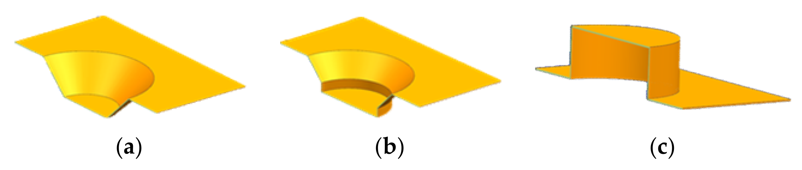
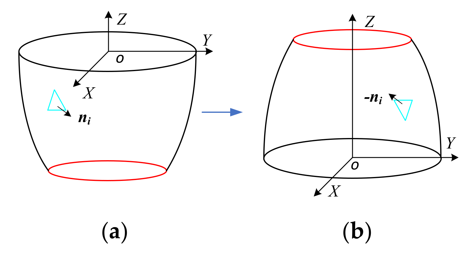
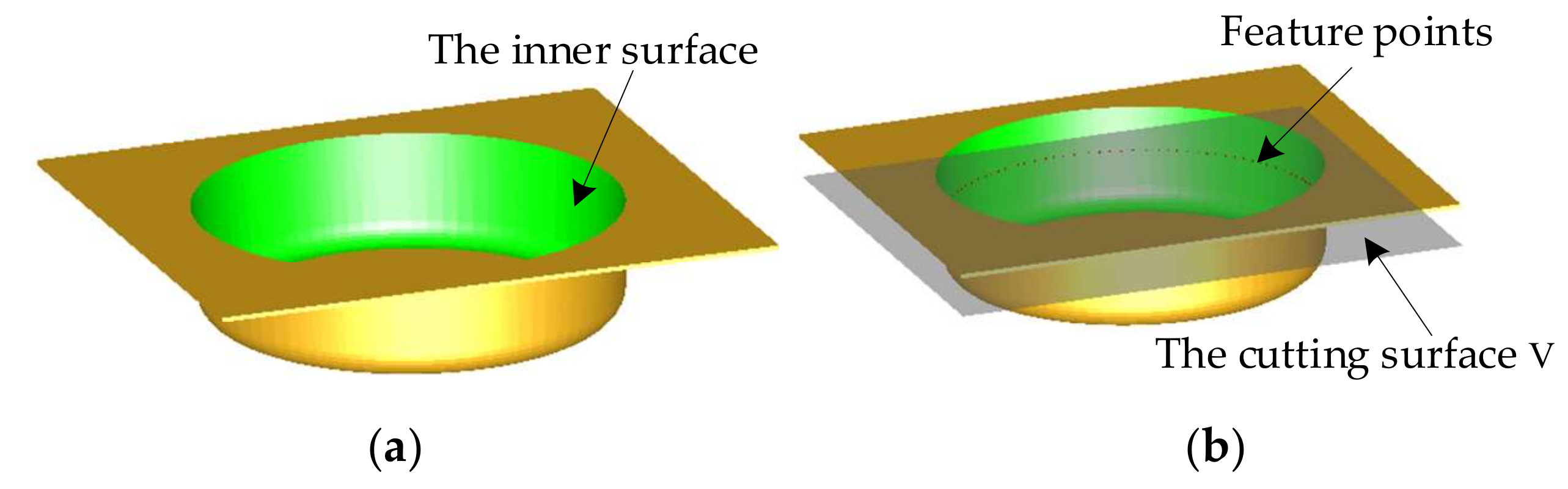
Extract the inner surface of the STL (Stereo Lithography) model of straight-wall parts. The STL model consists of triangular patches and their normal vectors. The triangular patches with the Z coordinate the value of the normal vector ni in the interval (0,1]) are extracted as the inner surface.
(2)
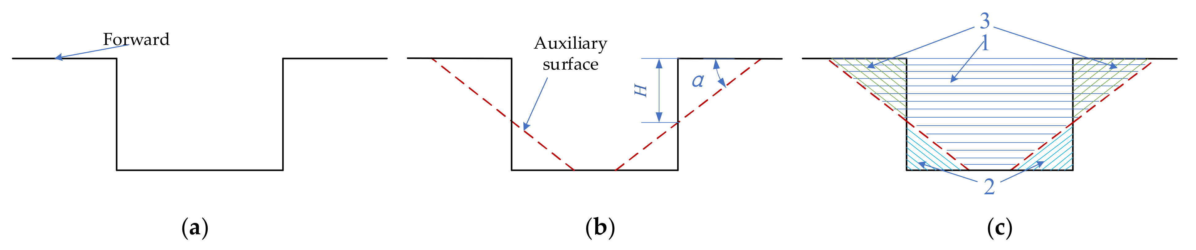
Set the inclination angle of the auxiliary surface α . Firstly, the forming angle of each triangular patch on the inner surface is calculated θ i = cos 1 ( n i · s n i ) and the maximum forming angle θ m a x is found, where s (0,0,1) is the normal vector of the horizontal plane; Then, the inclination angle   α of the auxiliary surface is set by the user according to the maximum forming angle θ m a x .
(3)
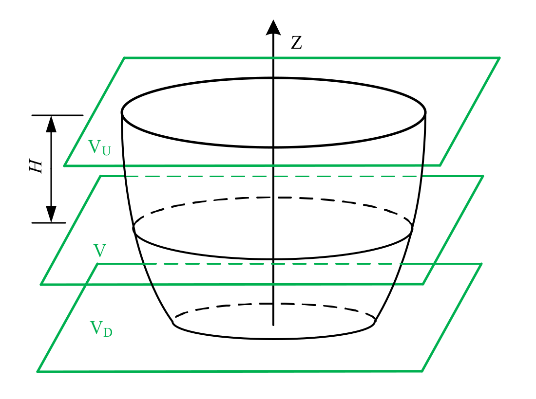
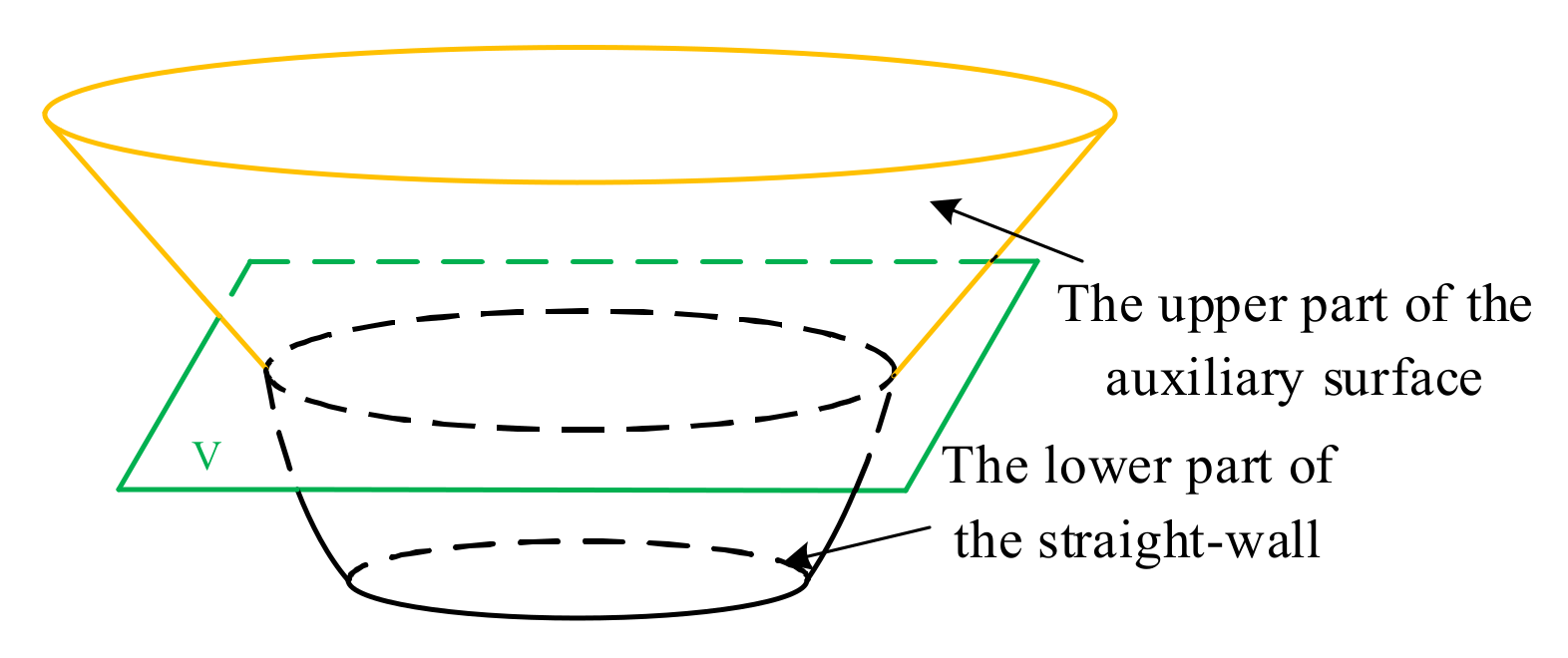
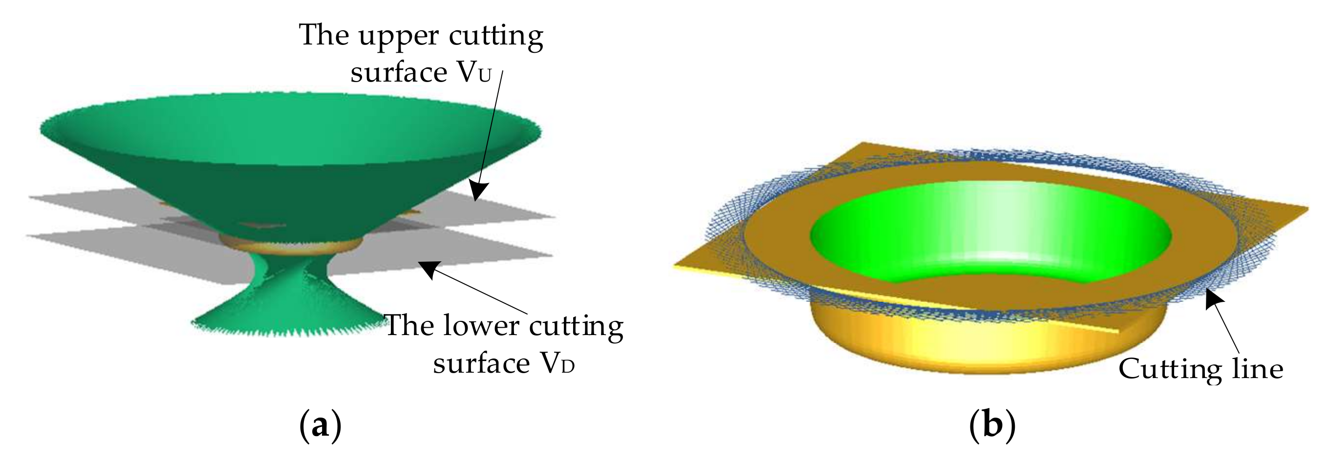
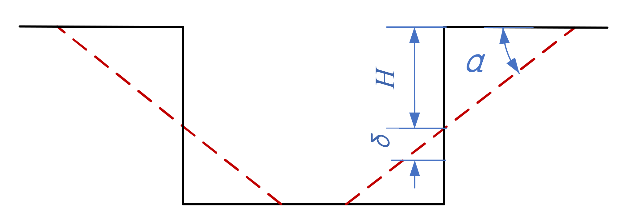
Generate the cutting surface through the triangular patch vertices with the maximum and minimum Z coordinate values on the inner surface, respectively, to generate the horizontal cutting surface VU (generally coincident with the top surface of the model) and VD (generally coincident with the bottom surface of the model), and generate a cutting surface V that is parallel to the cutting surface VU and is located at a distance of H from the cutting surface VU (Figure 6).
(4)
Generate feature points. The extracted inner surface is cut with the cutting surface V, that is, the cutting surface V intersects each edge of the triangular patch at a point, which is the feature point Dj (Figure 6).
(5)
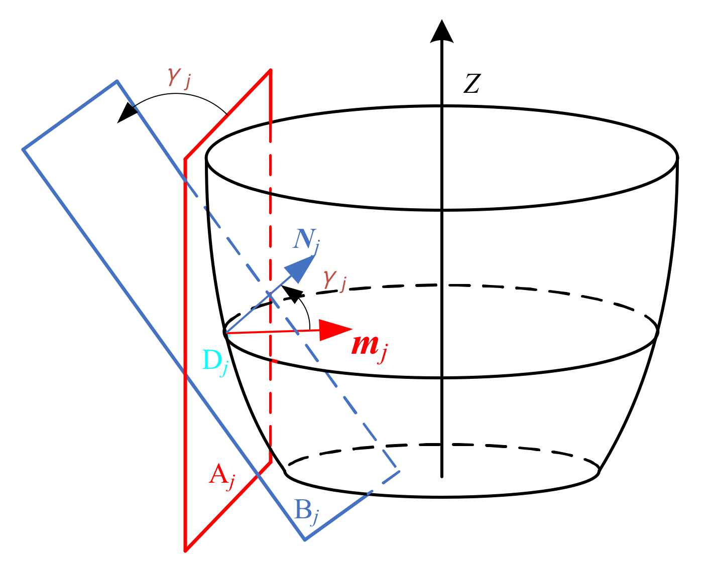
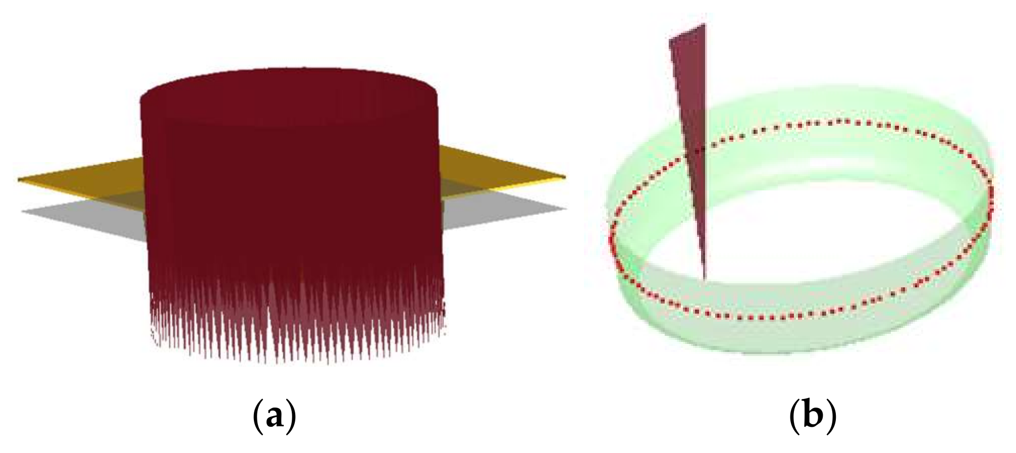
Generate vertical faces. A vertical plane Aj is established through the feature point Dj (Figure 7). The direction of the normal vector mj of the vertical plane Aj is the direction of the angular bisector between feature points, and the size is the unit vector.
(6)
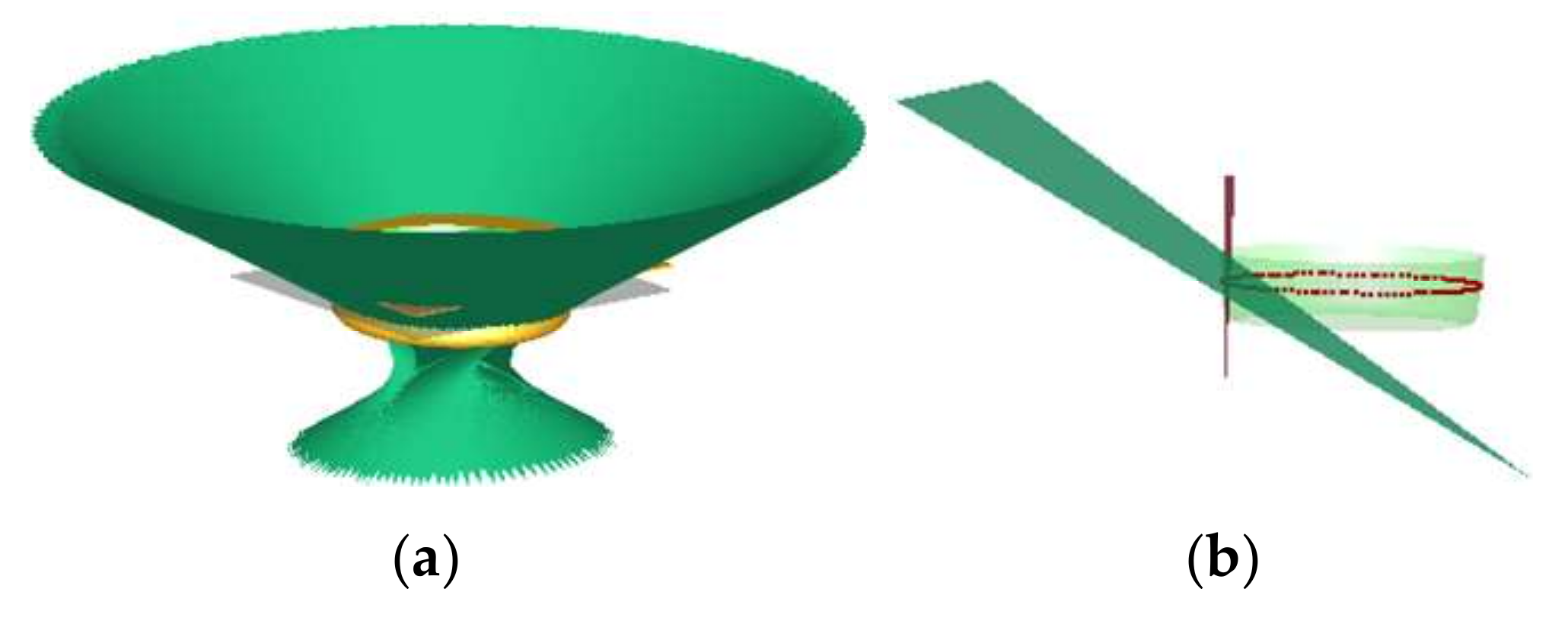
Rotate the vertical plane. Rotate the vertical plane Aj by γ j = 90 ° α   around the point Dj to obtain the plane Bj. That is, the normal vector mj of the vertical plane Aj is rotated γ j counterclockwise around the point Dj in the plane determined by the vertical line passing through the point Dj and the normal vector mj of the vertical plane Aj to obtain the normal vector Nj of the plane Bj (Figure 7). Then, the equation of the plane Bj is obtained by using the point Dj and the normal vector Nj, as shown in Figure 7.
(7)
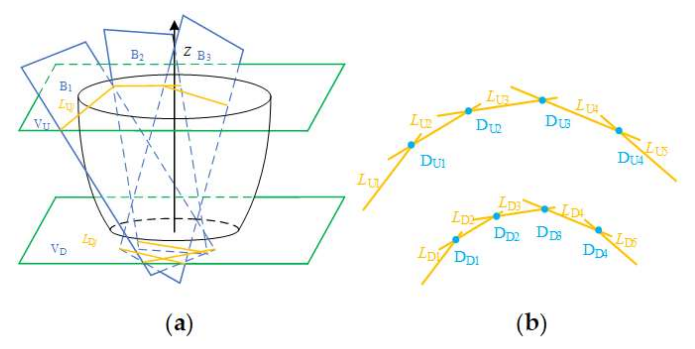
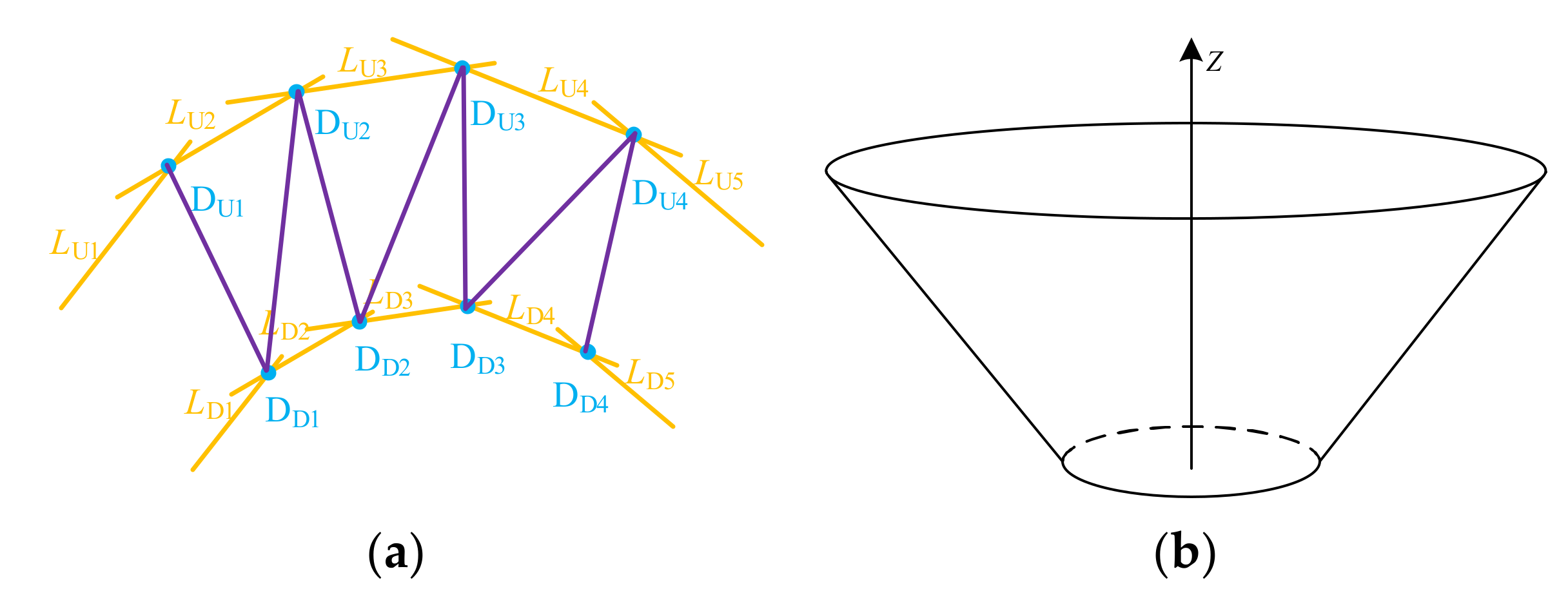
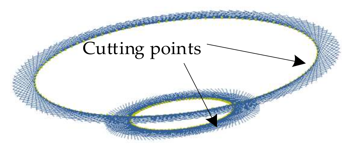
For the upper and lower cutting surfaces, judge whether the rotated plane Bj coincides; if it coincides with the previous plane, remove this plane. The cutting line LUj is obtained by cutting the rotated plane Bj using the cutting surface VU, and the cutting line LDj is obtained by cutting the rotated plane Bj using the cutting surface VD (Figure 8a). The upper cutting points DUj are the intersection points of the cutting line LUj and the lower cutting points DDj are the intersection points of the cutting line LDj (Figure 8b).
(8)
Generate the auxiliary surface. The cutting points on the upper and lower cutting lines are connected alternately to construct a triangular patch (Figure 9a) to obtain the auxiliary surfaces (Figure 9b).

3.2. Generation Algorithm for Each Intermediate Forming-Stage Model

According to Figure 3, the second-stage forming model can directly adopt the auxiliary surface. The second-stage forming model is composed of the part on the straight-wall part below the cutting surface V (Figure 6) and the part on the auxiliary surface above the cutting surface V. Therefore, the auxiliary surface and the straight-wall part are divided into two parts using the cutting surface V, the upper part of the auxiliary surface, and the lower part of the straight-wall part, respectively, and the points on the cutting line are connected in turn to form a new triangular patch. The upper part of the auxiliary surface and the lower part of the straight-wall part are combined into a new surface; thus, the second-stage forming model is obtained (Figure 10).
The third-stage forming model is the part on the straight-wall part above the cutting surface V (Figure 6). In order to extrude forming area 3 from the reverse side, it is necessary to turn the straight-wall part over and take the part on the straight-wall part above the cutting surface V (Figure 6). To this end, first extract the inner surface of the straight-wall part; then, convert the vertices (xi,yi,zi) of each triangular patch to (−xi,yi,zi) and the normal vector ni of the triangular patch to −ni; finally, connect the converted triangular patches to obtain the third-stage forming model, as shown in Figure 11.

3.3. Case Studies

In this paper, the first-stage forming model, the second-stage forming model and the third-stage forming-model-generation software system are developed by using C language, OpenGL graphics library and VC + + 6.0 under a Windows 7 environment. The feasibility of the generation algorithm of the auxiliary surface, the first-stage forming model, the second-stage forming model, and the third-stage forming model are verified by taking the straight-wall part model shown in Figure 12a as an example. The forming angle θ of the straight-wall part is 85°, the depth h is 23 mm (Figure 12b), and the section shape is ellipse (Figure 12c), the semimajor axis is 50 mm, and the semiminor axis is 45 mm.
Figure 13a shows the inner surface of the straight-wall part. Figure 13b shows the feature points obtained by cutting the inner surface with a cutting surface V with a height H of 10 mm.
Figure 14a shows a vertical plane established through each feature point. Figure 14b shows a vertical plane passing through a certain feature point.
In the case studies, the inclination angle of the auxiliary surface α is set to 30°. The rotated plane is generated by rotating the vertical plane of 60°. The generated rotation plane is shown in Figure 15a. In order to more clearly show the rotation effect of the vertical plane, one of the rotated planes obtained by rotating the vertical plane that passes through a certain feature point is shown in Figure 15b.
Figure 16a shows the rotated planes that are intersected with the upper and lower cutting surfaces, and Figure 16b shows cutting lines.
Figure 17 shows the intersection points obtained by the intersection of cutting lines, that is, cutting points.
Figure 18a shows an auxiliary surface constructed by alternately connecting the upper and lower cutting points, that is, the first-stage forming model. Figure 18b shows the second-stage forming model obtained by combining the lower part of the straight-wall part located on the cutting surface V and the upper part of the auxiliary surface. Figure 18c shows the third-stage forming model obtained by turning over the straight-wall part of 180° and taking the part on the cutting surface V on the straight-wall part surface.

4. Generation of Forming Toolpath for Each Stage

4.1. First-Stage Forming-Toolpath Planning and Generation

The purpose of the first-stage forming is to reduce the forming angle and ensure the smoothness of the forming surface as much as possible, so as to pave the way for the second-stage forming and the third-stage forming. The contour toolpath [32] is adopted for the first-stage forming toolpath.

4.2. Second- and Third-Stage Forming-Toolpath Planning and Generation

The second- and third-stage forming toolpath adopt the parallel toolpath with a stretching angle [33]. When generating the third-stage forming toolpath, it should be noted that in the extrusion from the forward and reverse sides in the second-stage forming and the third-stage forming, creases may occur at the height H of the straight-wall part. Therefore, the third-stage forming toolpath is generated at the starting position of H + δ (Figure 19). δ can be determined by the user according to the forming tool diameter and forming accuracy requirements. It can also be calculated more accurately according to the forming tool diameter, forming accuracy requirements, residual height, layer spacing of toolpath, and surface characteristics, but these contents cannot be touched in this paper, which will be further studied in the follow-up study.

4.3. Case Studies

Figure 20a shows the tool location surface of the first-stage forming model. Figure 20b shows the generated contour toolpath with the dispersed pressing-down points when the layer spacing Δh and the slope angle ε are set to 0.8 mm and 60°, respectively.
Figure 21a shows the surface of the second-stage forming area and Figure 21b shows the tool location surface of the second-stage forming area. Figure 21c shows the generated second-stage forming toolpath when the layer spacing Δh1 and the stretching angle ψ are set as 0.2 mm and 15°, respectively.
Figure 22a shows the surface of the third-stage forming area and Figure 22b shows the tool location surface of the third-stage forming area. Figure 22c shows the generated third-stage forming toolpath when the layer spacing Δh1 and the stretching angle ψ and δ are set as 0.2 mm, 15°, and 3 mm, respectively.

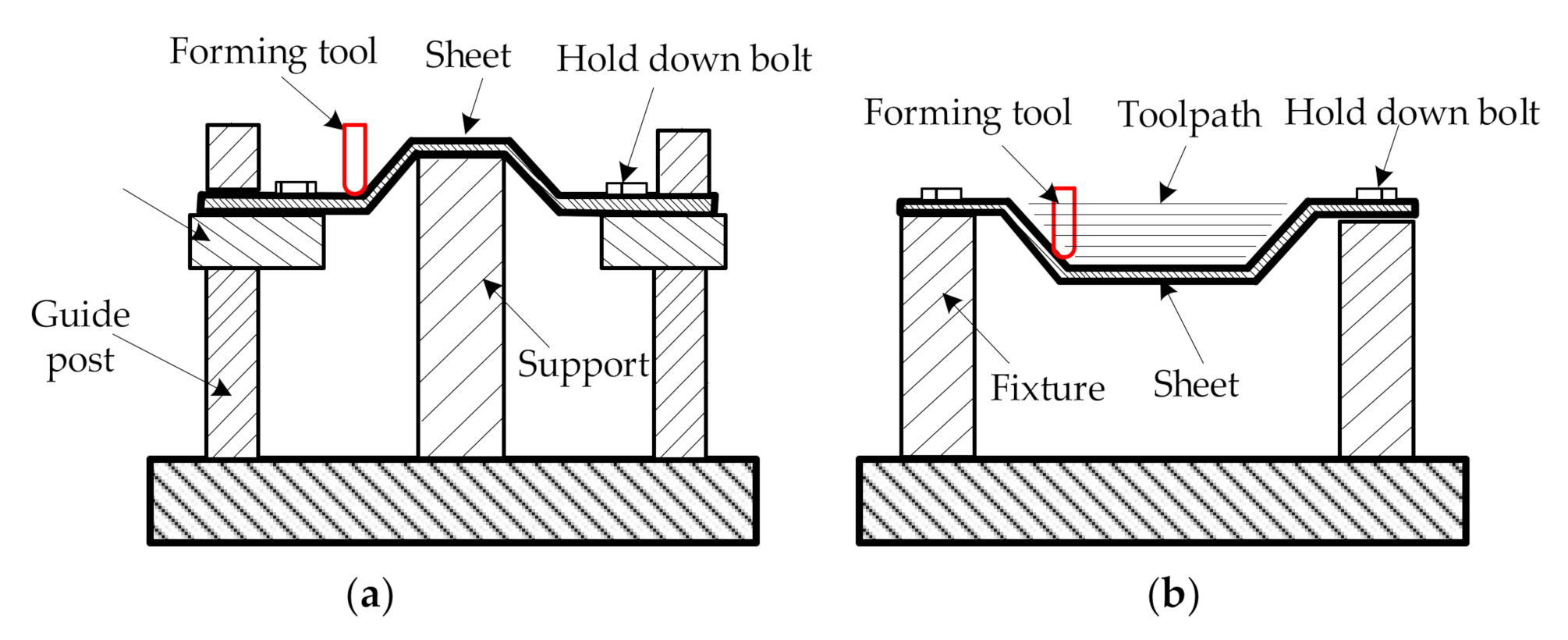
5. Forming Experiment

5.1. Forming Experiment Process

In order to verify the feasibility and effectiveness of the method proposed in this paper, a forming experiment based on the traditional multistage forming and the proposed method is conducted by taking the straight-wall part model shown in Figure 12a as the test model.
The traditional multistage forming method is shown in Figure 23. The first-stage forming angle θ1 is 30° and the first-stage forming depth h1 is 13 mm; the second-stage forming angle θ2 is 60° and the second-stage forming depth h2 is 18 mm.
Figure 24a shows the support model for the traditional multistage forming, whose internal surfaces are generated according to the outer surface of the straight-wall part (Figure 12a). Figure 24b shows the support model for the proposed method in the paper, in which the round table surface A is used for the first-stage forming, and the cylindrical surface B is used for the second-stage forming. Firstly, in order to conduct the first-stage forming and the second-stage forming, the internal surfaces of the support are generated according to the outer surface of the first- and second-stage-forming model (Figure 18). Secondly, because the sheet needs to be turned over in the third-stage forming, positioning holes (for installing the positioning pin) are set on the support to reduce the turning-over error.
According to the support model shown in Figure 24, the actual supports are fabricated by using a milling process and nylon material, as shown in Figure 25a. Figure 25b is the support for the traditional multistage forming and Figure 25c is the support for the proposed method.
The forming experiments are carried out on the three-axis CNC machining center shown in Figure 26a. The forming equipment (Roland DG Corporation, Osaka, Japan) is shown in Figure 26b, in which the 1060 aluminum sheet (density 2700 kg/m3, modulus of elasticity 55.94 GPa, poisson’s ratio 0.324, yield stress 153.6 MPa, tangential modulus 2.9 GPa, hardening coefficient 0.1978.) with a size of 200 mm × 200 mm × 1 mm is used as the forming sheet; the forming tool is a hemispherically shaped tool with a diameter of 10 mm. The spindle speed, the feed rate, and the layer spacing of the toolpath are set as 600 rmp, 840 mm/min, and 0.2 mm, respectively. Engine oil is used as the lubricating oil.

5.2. Analysis of Forming Experiment Results

Figure 27a shows the traditional multistage forming process, and Figure 27b shows the experimental part after forming. It can be seen that the experimental part has been broken at a depth of 12 mm.
Figure 28a shows the first-stage forming process based on the proposed method, in which the inclination angle α is 30° and the height H is 10 mm. Figure 28b shows the circular platform-shaped part formed by first-stage forming.
Figure 29a shows the second-stage forming process. Figure 29b shows the part formed by the second-stage forming.
Figure 30a shows the process of turning over the second-stage forming part and performing the third-stage forming. Figure 30b shows the third-stage forming part, in which the circular table surface of the second stage is formed into a cylindrical surface.
Figure 31 shows the experimental part after the third-stage forming. Figure 31a is a forward view of the experimental part, and Figure 31b is a reverse view of the experimental part. It can be seen that the appearance quality of the experimental part is relatively good, but there is slight sinking at the bottom.
Because the experimental parts with traditional multistage forming are broken, this paper only analyzes the experimental part with the proposed method from the thickness distribution and contour dimension accuracy, so as to prove the feasibility of the strategy proposed in this paper.

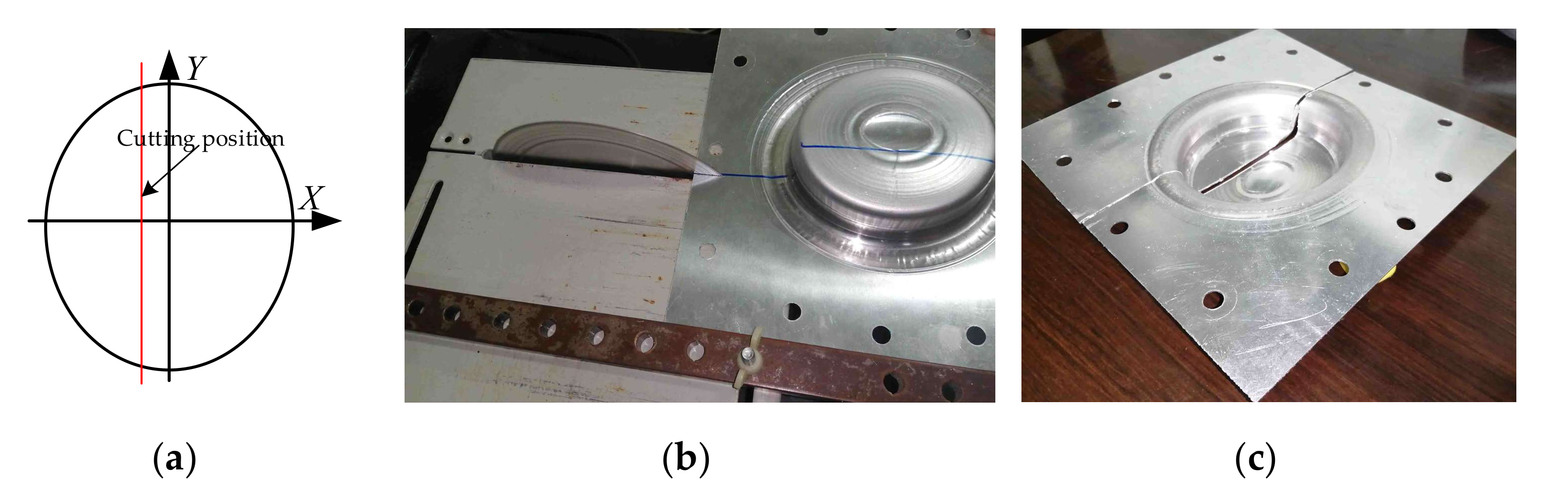
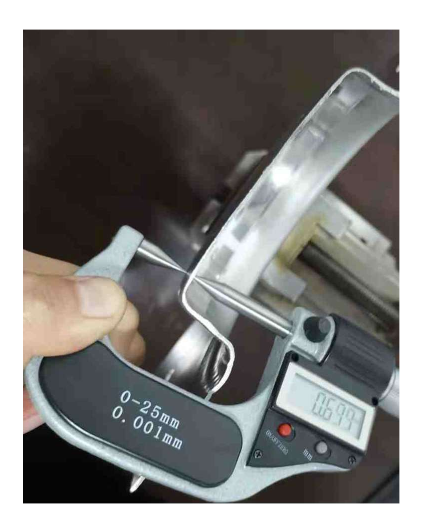
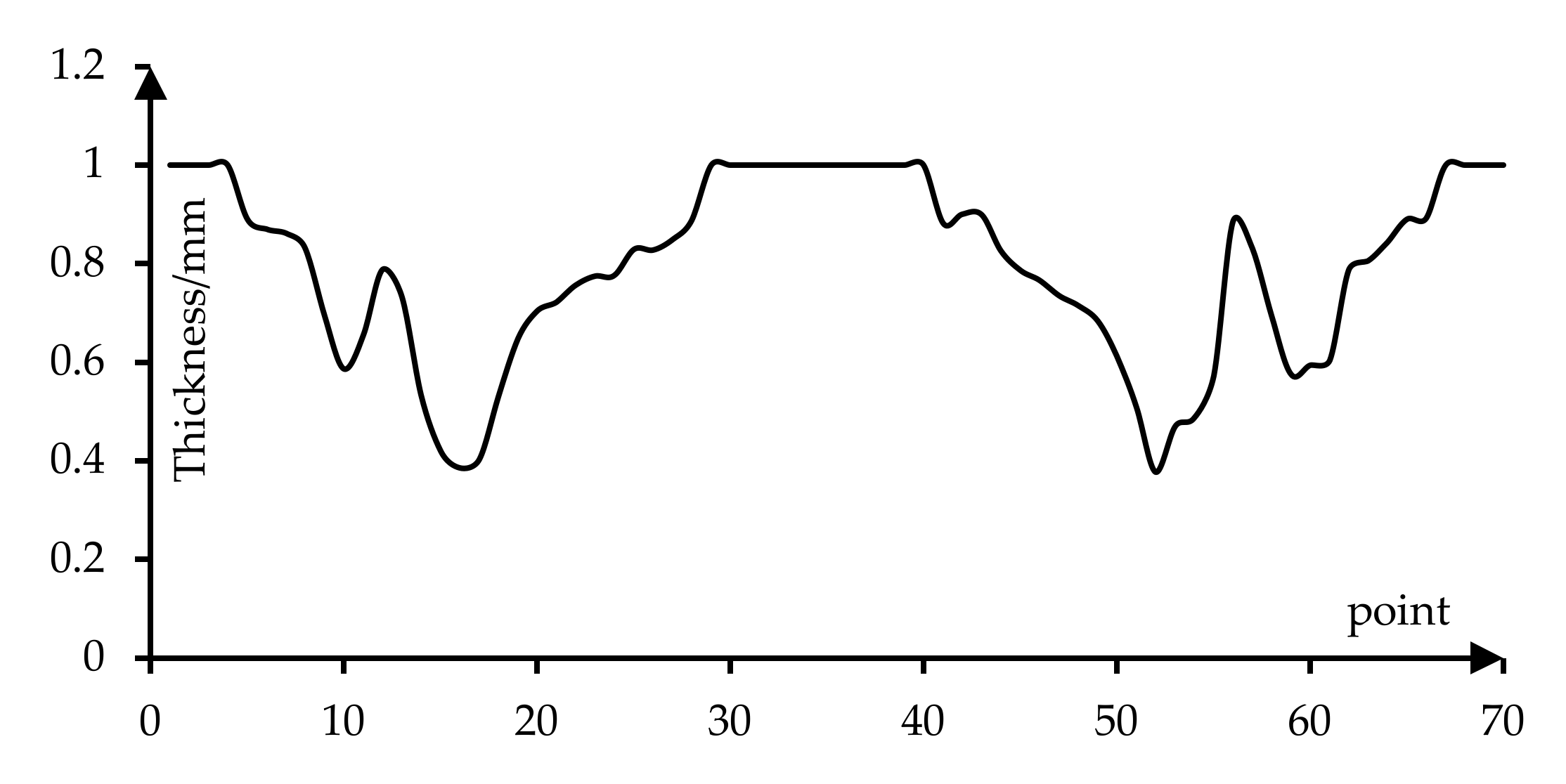
5.2.1. Thickness Distribution

To measure the sheet thickness of the section at the x = 0, the experimental part has been cut by using a bench mill at a certain distance from the Y-axis as shown in Figure 32a (the distance is between 5 mm and 20 mm), Figure 32b shows the cutting process of the experimental part, and Figure 32c shows the experimental part after cutting.
In order to accurately measure the thickness distribution of the experimental part on the x = 0 section, the experimental part was measured by a pointed micrometer (Figure 33). The measured results were sorted and the thickness distribution curve was drawn (Figure 34).
Figure 34 shows a thickness-distribution curve of an experimental part formed by using the proposed forming method. As can be seen, the thickness value in the transition area between the side wall and the bottom is the smallest, and the minimum thickness value is 0.378 mm. On the side wall of the experimental part (in the horizontal axis are (4,17) and (50,67)), the thickness will become thinner with the increase in forming depth. The thickness of areas (in the horizontal axis are (10,14) and (55,59)) will increase because the two areas (10,14) and (55,59) are near the overturned surface.

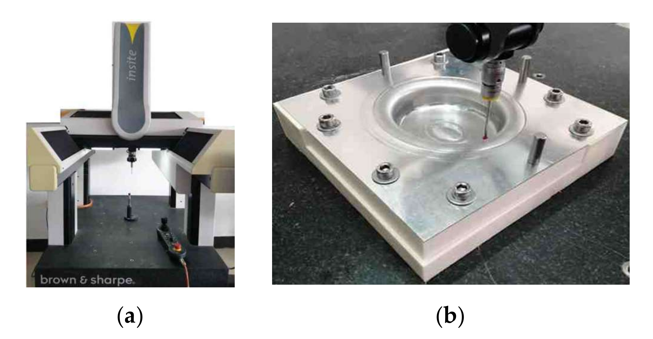
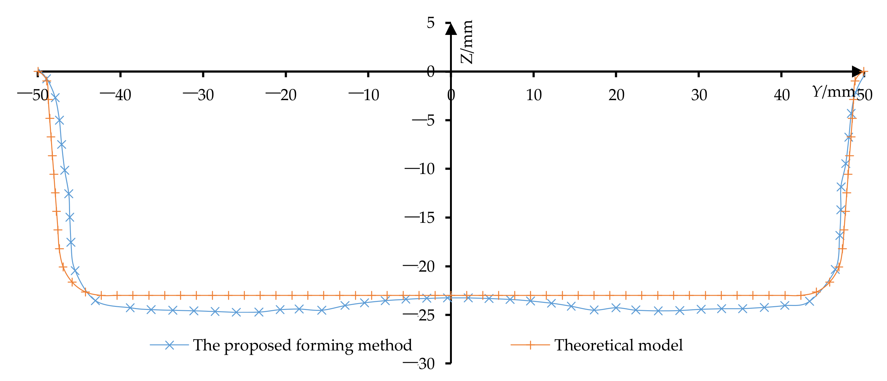
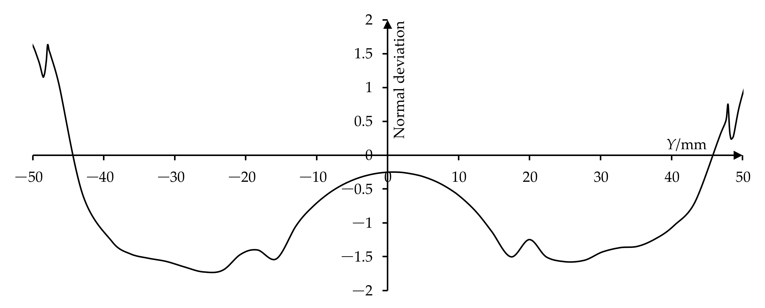
5.2.2. Profile Curve

In order to obtain the profile curve at the x = 0 section of the experimental part, the experimental part was measured by the hexagon three-coordinate measuring instrument (Figure 35a). Figure 35b shows the contour measurement process, and the measurement-spacing changes in the range of 1–2 mm.
Figure 36 shows the contour curve of the experimental part formed by using the proposed method. As can be seen from the figure, there is subsidence in the area of [−45~−10, 10~45]. Compared with the theoretical model, the normal direction deviation of the left side wall is larger and the deviation of the right side wall is smaller.
In order to analyze the normal direction deviation between the experimental part based on the proposed method and the theoretical model, the normal deviation curve shown in Figure 37 is drawn. The normal direction deviation of the experimental part is mainly distributed between −1.5 and 1 mm, and the average deviation is 1.0521 mm. The maximum normal deviation at x = −25.9694 mm is is the largest and its value −1.7246 mm.

6. Conclusions

(1)
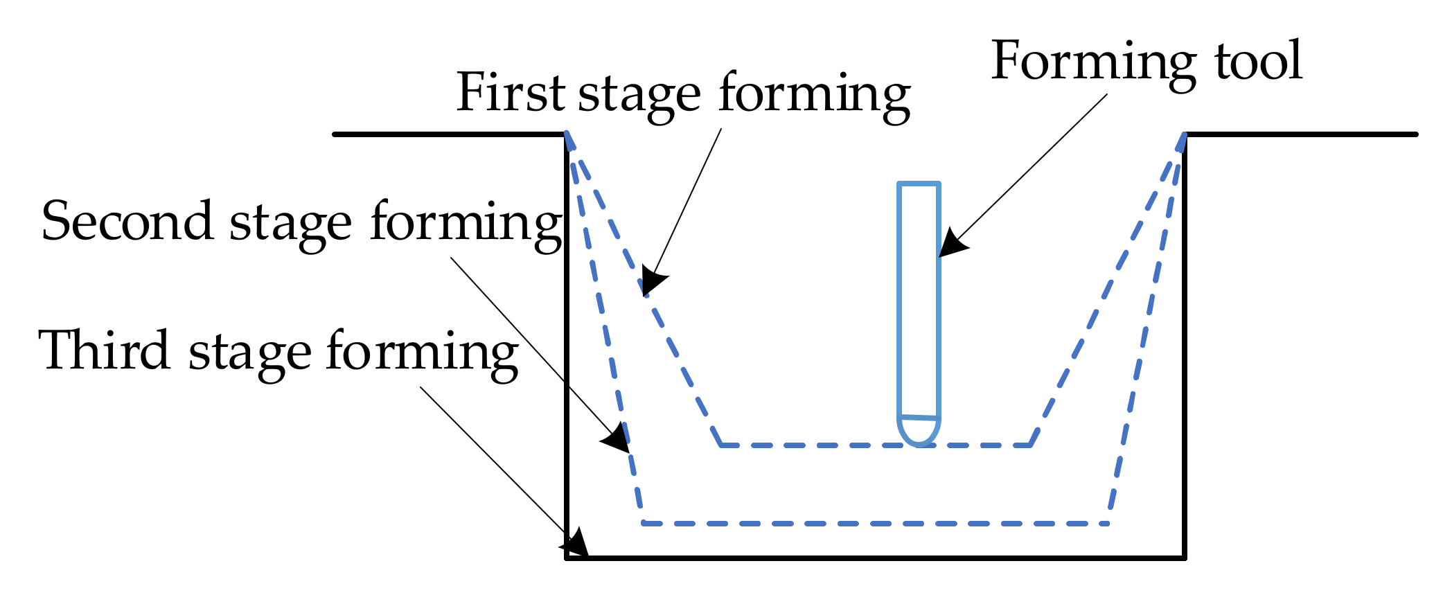
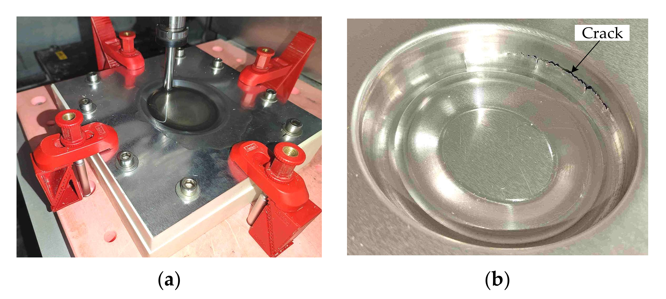
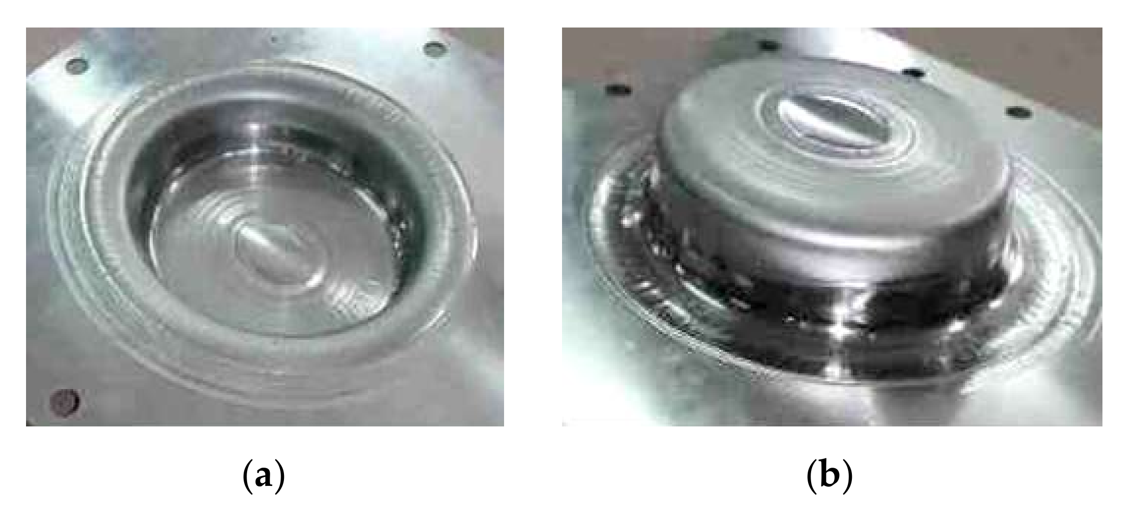
The straight-wall part with a forming angle of 85° cannot be formed by the traditional multistage forming strategy mentioned in this paper. The sheet was broken during the third-stage forming.
(2)
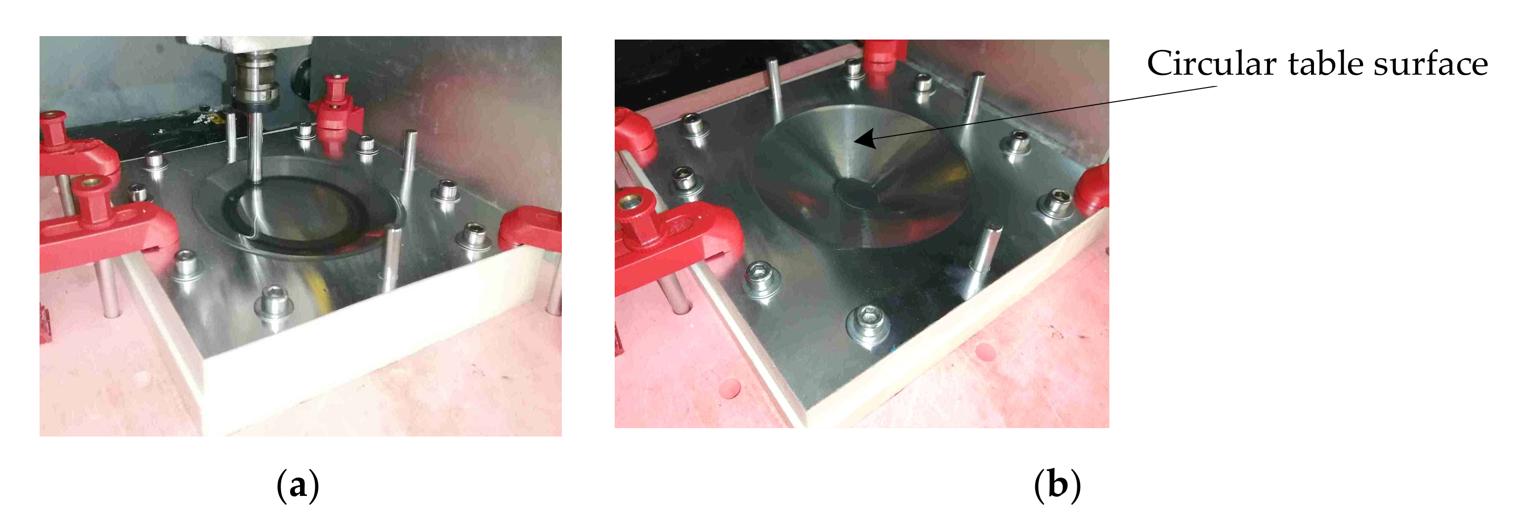
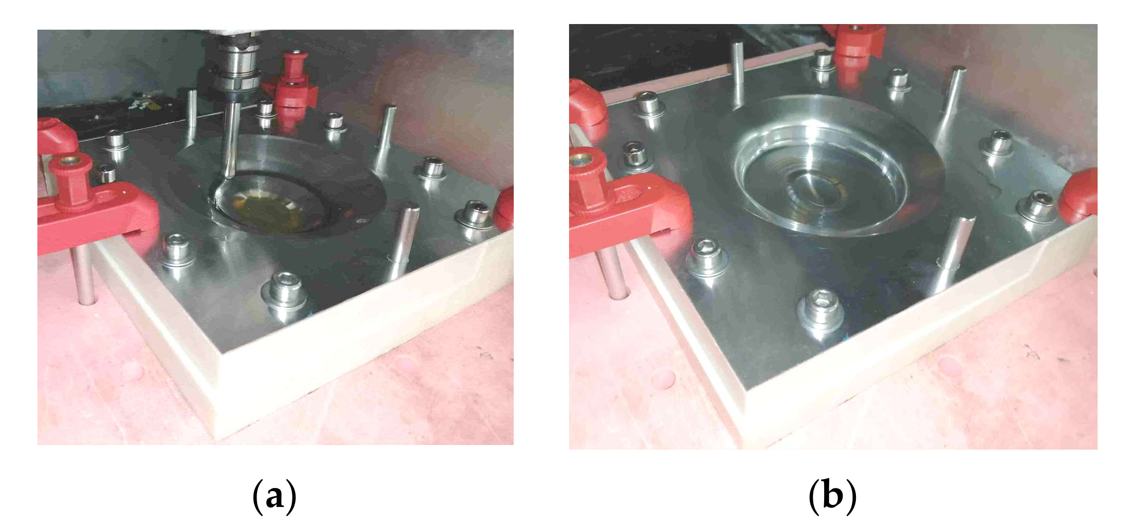
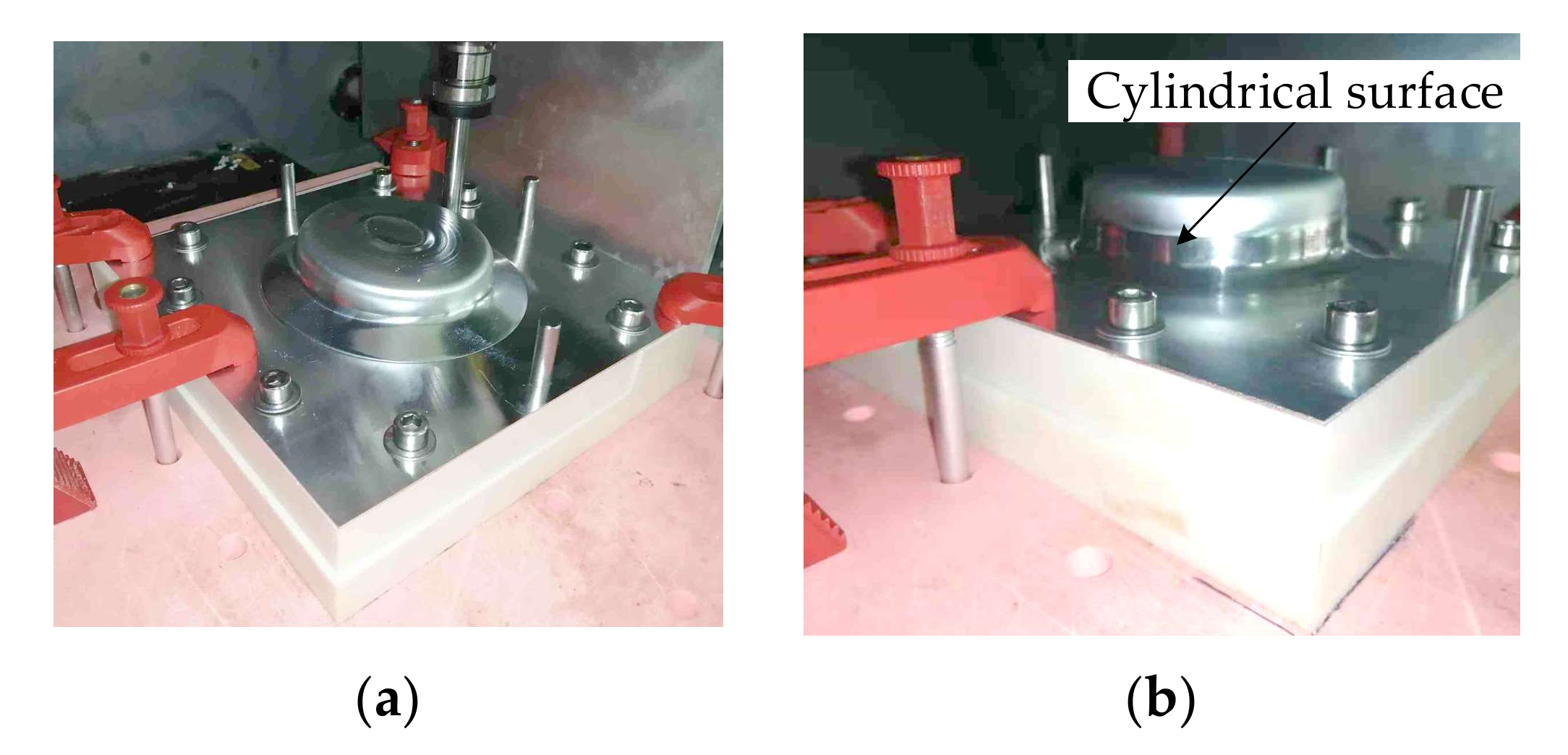
The straight-wall part with a forming angle of 85° can be successfully formed by using the proposed method in this paper, and the appearance quality is better. The profile-dimension accuracy and thickness distribution of the experimental part are good, and its minimum thickness is 0.378 mm.
(3)
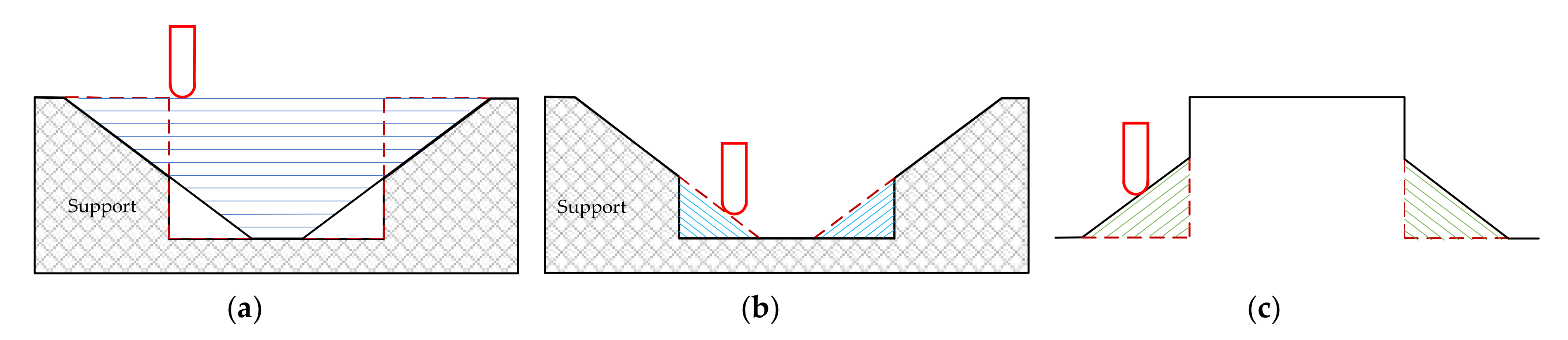
Compared with traditional negative multistage forming, under the supporting die, the proposed method can increase the area of the sheet metal participating in forming, which effectively increases the thickness of the sheet-metal part and is suitable for the straight-wall part model with narrow internal space.
(4)
The zoning of straight-wall parts can be adjusted by controlling the inclination angle α and height H, so that the amount of materials inside and outside the model that participate in the forming can be adjusted; additionally, the reasonable partition of straight-wall parts can be obtained to make the thickness distribution of the straight-wall parts more uniform.
(5)
In future work, it is necessary to find the best combination of the inclination angle α and height H. In addition, the double-sided CNC incremental forming technology is expected to be used in the proposed method so that the forward- and reverse-extrusion process can be conducted at the same time to reduce the errors occurring in the sheet-turnover process.

Author Contributions

Software, formal analysis, writing, and experiment, G.C.; conceptualization, methodology, and algorithms, H.Z.; methodology and supervision, D.J. All authors have read and agreed to the published version of the manuscript.

Funding

This research received no external funding. The APC was funded by the 2022 scientific promotion program of Jeju National University.

Institutional Review Board Statement

Not applicable.

Informed Consent Statement

Not applicable.

Data Availability Statement

Not applicable.

Conflicts of Interest

The authors declare no conflict of interest.

References

  1. Pratheesh, K.S.; Elangovan, S.; Mohanraj, R.; Boopathi, S. A comprehensive review in incremental forming on approaches of deformation analysis and surface morphologies. Mater. Today Proceed. 2021, 43, 3129–3139. [Google Scholar] [CrossRef]
  2. Shakir, G.; Hengan, O. Surface roughness analysis of medical grade titanium sheets formed by single point incremental forming. Int. J. Adv. Manuf. Technol. 2021, 114, 2975–2990. [Google Scholar]
  3. Pratheesh, K.S.; Elangovan, S.; Mohanraj, R.; Boopathi, S. Real-time applications and novel manufacturing strategies of incremental forming: An industrial perspective. Mater. Today Proceed. 2021, 46, 8153–8164. [Google Scholar]
  4. Harish, K.N.; Anupam, A. Residual stress inclusion in the incrementally formed geometry using Fractal Geometry Based Incremental Toolpath (FGBIT). J. Mater. Process. Technol. 2020, 279, 116575. [Google Scholar]
  5. Siddiqi, M.U.R.; Corney, J.R.; Sivaswamy, G.; Amir, M.; Bhattacharya, R. Design and validation of a fixture for positive incremental sheet forming. Proc. Inst. Mech. Eng. Part B J. Eng. Manuf. 2017, 232, 629–643. [Google Scholar] [CrossRef] [Green Version]
  6. Ben, K.N.; Thiery, S. Incremental sheet forming with active medium. CIRP Ann. 2019, 168, 313–316. [Google Scholar]
  7. Zhu, H.; Cheng, G.X.; Won, J.D. Comparison of the positive and negative two points incremental forming quality. J. Phys. Conf. Ser. 2021, 1922, 012012. [Google Scholar] [CrossRef]
  8. Kumar, D.S.; Ethiraj, N. Improvement of wall angle in AISI 304 stainless steel cup using five stage single point incremental forming. Int. J. Veh. Struct. Syst. 2020, 12, 17–21. [Google Scholar]
  9. Li, Z.F.; Lu, S.H.; Zhang, T.; Feng, T.H.; An, Z.G.; Xue, C.C. Numerical prediction of ductile fracture in multi-stage single point incremental forming based on phenomenological modified Mohr–Coulomb. Measurement 2020, 154, 107505. [Google Scholar] [CrossRef]
  10. Vignesh, G.; Pandivelan, C.; Narayanan, C.S. Review on multi-stage incremental forming process to form vertical walled cup. Mater. Today Proceed. 2020, 27, 2297–2302. [Google Scholar] [CrossRef]
  11. Zhu, H.; Liu, L.T. Research the CNC incremental forming of straight-wall parts based on a virtual auxiliary body. J. Mater. Process. Technol. 2021, 288, 116841. [Google Scholar] [CrossRef]
  12. Gianluca, B.; Marco, G.; Livan, F.; Fabrizio, M. Multi-directional vs. mono-directional multi-step strategies for single point incremental forming of non-axisymmetric components. J. Manuf. Process. 2020, 55, 22–30. [Google Scholar]
  13. Li, X.Q.; Han, K.; Xu, P.; Wang, H.B.; Li, D.S.; Li, Y.L.; Li, Q. Experimental and theoretical analysis of the thickness distribution in multistage two point incremental sheet forming. Int. J. Adv. Manuf. Technol. 2020, 107, 191–203. [Google Scholar] [CrossRef]
  14. Li, X.Q.; Han, K.; Li, D.S. Multi-Stage two point incremental sheet forming. J. Phys. Conf. Ser. 2018, 1063, 012064. [Google Scholar] [CrossRef]
  15. Grimm, T.J.; Mears, L. Investigation of a radial toolpath in single point incremental forming. Procedia Manuf. 2020, 48, 215–222. [Google Scholar] [CrossRef]
  16. Ömer, S. Effect of operational parameters on incremental forming of low-alloy sheet metals and its optimization. Adv. Mater. Process. Technol. 2021, 7, 71–84. [Google Scholar]
  17. Ajay, K.; Vinay, S.; Sujata, N.; Amit, K.; Ankit, T.; Anita, S. Impact of process variables on surface roughness in negative incremental forming process. Mater. Today Proceed. 2021, 5, 930–934. [Google Scholar]
  18. Hardik, R.D.; Devang, A.P.; Akash, B.P.; Divyangkumar, D.P.; Sekar, S. Experimental investigation of surface roughness for AA 3003-0 aluminium alloy using single point incremental forming. Mater. Today Proceed. 2021, 46, 8655–8662. [Google Scholar]
  19. Sherwan, M.N.; Imre, P. Artificial neural network for modeling and investigating the effects of forming tool characteristics on the accuracy and formability of thin aluminum alloy blanks when using SPIF. Int. J. Adv. Manuf. Technol. 2021, 114, 2591–2615. [Google Scholar]
  20. Ganesh, P.; Visagan, A.; Ethiraj, N.; Prabhahar, M.; Sendilvelan, S. Optimization of pyramid shaped single point incremental forming of AA5052 alloy sheet. Mater. Today Proceed. 2021, 45, 5892–5898. [Google Scholar] [CrossRef]
  21. Vjaykumar, M.D.; Chandramohan, D.; Gopalaramasubramaniyan, G. Experimental investigation on single point incremental forming of IS513Cr3 using response surface method. Mater. Today Proceed. 2020, 21, 902–907. [Google Scholar] [CrossRef]
  22. Gupta, P.; Szekeres, A.; Jeswiet, J. Design and development of an aerospace component with single-point incremental forming. Int. J. Adv. Manuf. Technol. 2019, 103, 3683–3702. [Google Scholar] [CrossRef]
  23. Vedat, T. Optimization of incremental forming of Low-Alloy High-Yield-Strength HC300LA sheet using a rolling blank holder method. Steel Res. Int. 2021, 92, 2000512. [Google Scholar]
  24. Wu, S.; Ma, Y.; Gao, L.; Zhao, Y.; Rashed, S.; Ma, N. A novel multi-step strategy of single point incremental forming for high wall angle shape. J. Mater. Process. 2020, 56, 697–706. [Google Scholar] [CrossRef]
  25. Li, J.C.; Yang, F.F.; Zhou, Z.Q. Thickness distribution of multi-stage incremental forming with different forming stages and angle intervals. J. Cent. South Univ. 2015, 22, 842–848. [Google Scholar] [CrossRef]
  26. Suresh, K.; Regalla, S.P.; Kotkundae, N. Finite element simulations of multi stage incremental forming process. Mater. Today Proceed. 2018, 5, 3802–3810. [Google Scholar] [CrossRef]
  27. Ndip-Agbor, E.; Cheng, P.; Moser, N.; Ehmann, K.; Cao, J. Prediction of rigid body motion in multi-pass single point incremental forming. J. Mater. Process. Technol. 2019, 269, 117–127. [Google Scholar] [CrossRef]
  28. Dai, P.P.; Chang, Z.D.; Li, M.; Chen, J. Reduction of geometric deviation by multi-pass incremental forming combined with tool path compensation for non-axisymmetric aluminum alloy component with stepped feature. Int. J. Adv. Manuf. Technol. 2019, 102, 809–817. [Google Scholar] [CrossRef]
  29. Li, J.C.; Hu, J.B.; Pan, J.J. Thickness distribution and design of a multi-stage process for sheet metal incremental forming. Int. J. Adv. Manuf. Technol. 2012, 62, 981–988. [Google Scholar] [CrossRef]
  30. Jung, K.S.; Yu, J.H.; Chung, W.J.; Lee, C.W. Tool path design of the counter single point incremental forming process to decrease shape error. Materials 2020, 13, 4719. [Google Scholar] [CrossRef]
  31. Pranav, G.; Alexander, S.; Jacob, J. Manufacture of an aerospace component with hybrid incremental forming methodology. Int. J. Mater. Form. 2021, 14, 293–308. [Google Scholar]
  32. Zhu, H.; Zhang, W.; Ju, J. Generation of the underdraught points uniformly distributed contour tool path for CNC incremental forming. Appl. Mech. Mater. 2014, 635, 511–514. [Google Scholar] [CrossRef]
  33. Zhu, H.; Cheng, G.X.; Jung, D.W. Toolpath planning and generation for multi-stage incremental forming based on stretching angle. Materials 2021, 14, 4818. [Google Scholar] [CrossRef] [PubMed]
Figure 1. Incremental forming types: (a) positive incremental forming; (b) negative incremental forming.
Metals 12 00459 g001
Figure 2. Negative multistage incremental forming.
Metals 12 00459 g002
Figure 3. Division of forming area: (a) the straight-wall part model; (b) auxiliary surface; (c) forming area.
Metals 12 00459 g003
Figure 4. Three stages of forming: (a) the first stage; (b) the second stage; (c) the third stage.
Metals 12 00459 g004
Figure 5. The forming model of each stage: (a) the first stage; (b) the second stage; (c) the third stage.
Metals 12 00459 g005
Figure 6. Construction of the cutting surface.
Metals 12 00459 g006
Figure 7. Rotation of the vertical plane.
Metals 12 00459 g007
Figure 8. Intersection of the cutting surface and the rotating surface: (a) upper and lower cutting lines; (b) upper and lower cutting points.
Metals 12 00459 g008
Figure 9. The auxiliary surface generation: (a) triangular meshing; (b) the first-stage forming model.
Metals 12 00459 g009
Figure 10. The second-stage forming-model generation.
Metals 12 00459 g010
Figure 11. Turn-over transformation of the straight-wall model: (a) before overturn; (b) after overturn.
Metals 12 00459 g011
Figure 12. The straight-wall part model: (a) three-dimensional model; (b) longitudinal section; (c) cross section.
Metals 12 00459 g012
Figure 13. Feature points generation: (a) the inner surface extraction; (b) the cutting surface and feature points.
Metals 12 00459 g013
Figure 14. Vertical-plane generation: (a) generated vertical planes; (b) the single vertical plane.
Metals 12 00459 g014
Figure 15. Rotation of the vertical plane: (a) the plane after rotation; (b) the single plane of rotation.
Metals 12 00459 g015
Figure 16. Intersection of cutting surfaces and rotated surface: (a) upper and lower cutting surfaces; (b) cutting lines.
Metals 12 00459 g016
Figure 17. Generation of the cutting points.
Metals 12 00459 g017
Figure 18. Forming model of each intermediate stage: (a) the first stage; (b) the second stage; (c) the third stage.
Metals 12 00459 g018
Figure 19. The starting position of the third-stage forming.
Metals 12 00459 g019
Figure 20. The first-stage forming toolpath: (a) the tool location surface; (b) the generated forming toolpath.
Metals 12 00459 g020
Figure 21. The second-stage forming toolpath: (a) the surface of forming area; (b) the tool location surface; (c) the generated forming toolpath.
Metals 12 00459 g021
Figure 22. The third-stage forming toolpath: (a) the surface of the forming area; (b) the tool location surface; (c) the generated forming toolpath.
Metals 12 00459 g022
Figure 23. The traditional multistage forming strategy.
Metals 12 00459 g023
Figure 24. Support model: (a) for traditional multistage forming; (b) for the proposed method.
Metals 12 00459 g024
Figure 25. The actual support: (a) milling process; (b) for the traditional multistage forming, (c) for the proposed method.
Metals 12 00459 g025
Figure 26. Forming equipment: (a) Roland 3D mold-engraving machine MDX-540; (b) the forming process.
Metals 12 00459 g026
Figure 27. The traditional multistage forming: (a) the forming process; (b) the experimental part.
Metals 12 00459 g027
Figure 28. The proposed forming method: (a) the first-stage forming process; (b) the part formed by the first-stage forming.
Metals 12 00459 g028
Figure 29. The proposed forming method: (a) the second-stage forming process; (b) the part formed by the second-stage forming.
Metals 12 00459 g029
Figure 30. The proposed forming method: (a) the third-stage forming process; (b) the part formed by the third-stage forming.
Metals 12 00459 g030
Figure 31. The experimental part: (a) the forward view (b) the reverse view.
Metals 12 00459 g031
Figure 32. Cutting: (a) the cutting position; (b) the cutting process; (c) the experimental part after cutting.
Metals 12 00459 g032
Figure 33. Thickness measurement.
Metals 12 00459 g033
Figure 34. Thickness-distribution curve.
Metals 12 00459 g034
Figure 35. Profile measurement: (a) the three-coordinate measuring instrument; (b) measurement process.
Metals 12 00459 g035
Figure 36. The profile curves.
Metals 12 00459 g036
Figure 37. Normal direction deviation of the profile curves.
Metals 12 00459 g037
Publisher’s Note: MDPI stays neutral with regard to jurisdictional claims in published maps and institutional affiliations.

