Article

Designing a Mixed Texture in Mg/Mg Laminated Composite via Bimetal Co-Extrusion to Ameliorate the Mechanical Anisotropy

1
School of Mechanical Engineering, Yangzhou University, Yangzhou 225127, China
2
National Engineering Research Center for Magnesium Alloys, Chongqing University, Chongqing 400044, China
3
School of Materials and Energy, Yunnan University, Kunming 650599, China
*
Author to whom correspondence should be addressed.
Submission received: 17 March 2022 / Revised: 31 March 2022 / Accepted: 6 April 2022 / Published: 7 April 2022
(This article belongs to the Special Issue Forming Mechanism for Extrusion of Metals and Alloys)

Abstract

:
Room-temperature (RT) mechanical anisotropy limits the broad applications of wrought magnesium (Mg) alloys. To weaken the anisotropy, here, we proposed a design idea to create a mixed texture. In the present study, we successfully fabricated the Mg-3Y/Mg-5Li (W3/L5, wt.%) laminated composite, having a mixed texture with a closely orthotropic shape, consisting of an ED-split component in the W3 layer and a TD-split in the L5 layer, via bimetal co-extrusion (ED and TD represent the extrusion and transverse directions, respectively). The mechanical results show that the W3/L5 laminated composite demonstrates a better isotropy at RT, indicating that forming a mixed texture is an effective method to reduce the anisotropy of wrought Mg alloys by bimetal co-extrusion. However, extremely poor interface shear strength, induced by rich O element voids on the interface, triggered poor interface bonding, leading to worse ultimate strength and elongation -to-failure. In future works, controlling co-extrusion parameters or implementing a suitable heat-treatment after extrusion will be necessary to further ameliorate the mechanical properties of the Mg/Mg laminated composites with mixed texture.

Graphical Abstract

1. Introduction

As one of the lightest structural materials, magnesium (Mg) and its alloys have attracted considerable attention for potential applications in the automotive industries. Due to a hexagonal close-packed (HCP) structure, Mg alloys tend to exhibit a strong mechanical anisotropy at room temperature (RT), which greatly restricts their industrial applications [1,2,3]. Therefore, this obvious mechanical anisotropy is urgently weakened, and even eliminated, to promote the development of Mg alloys.
In the last decade, material scientists have been committed to unveiling the origin of mechanical anisotropy, as well as the exploration of new methods conducted on the mechanical isotropy of Mg alloys. It is widely believed that texture results in mechanical anisotropy when an alloy is subjected to tensile stresses in different directions. In other words, if the texture is such that slip or twinning becomes more easily activated under an applied tensile stress, the flow stress generally becomes low; in contrast, it is higher without sufficient slip or twinning, as an alloy is applied to tension along the deformation hard orientation [4,5,6]. Texture randomization is, therefore, put forward as a strategy for the formation of an isotropic alloy.
In order to obtain an isotropic alloy with superior mechanical properties, impressive studies have been implemented using alloying element addition [7,8,9], severe plastic deformation [10,11] and pre-deformation processing [12,13]. Pei et al. [7] reported that a modified commercial AZ31 alloy with 0.3 wt.% Ca, namely AZX310 alloy, having a rather weak and scattered basal texture, showed a tensile isotropy with an elongation-to-failure of ~26% after multi-pass rolling and subsequent annealing. Hoseini-Athar et al. [10] showed that a new component with basal poles rotated 15~30° toward the extrusion direction (ED) was introduced during multi-pass constrained groove pressing (CGP), thereby making an annular texture in Mg-2Gd-3Zn (wt.%) alloy that exhibited a mechanical isotropy, accompanied with a yield strength of ~200 MPa and an elongation-to-failure of ~33%. With respect to an alloy with a special texture upon the pole axis completely rotated to one direction, i.e., Mg-3Li-3Al-1Zn (wt.%) alloy, pre-deformation and subsequent annealing provided an effective solution to introduce the specific twins for a scattered basal texture and improve the mechanical anisotropy [12].
However, the above-mentioned methods need complex processing to gain the desirable texture and mechanical properties. An enlightening insight on constructing a mixed texture through one-pass bimetal co-extrusion offers potential, i.e., Mg/Al [14,15,16] and Mg/Mg [17,18,19] composites. For example, an AZ31/7075 rod had a much lower tension-compression yield asymmetry than a monolithic Mg rod, since the formation of a mixed texture changed the deformation modes during tension-compression [15]. In an AZ31/W1 rod, combining a typical basal texture in the AZ31 layer with an off-basal texture in the W1 layer increased the basal slip activity in tension, but decreased the {10–12} extension twinning in compression, thereby creating a reduced yield asymmetry [17]. If a mixed texture can be used to sheet alloys as well, then an evident impact on reducing the mechanical anisotropy is expected. Therefore, an attempt has been made to develop an Mg/Mg laminated composite with a mixed texture.
In this work, Mg-3Y (W3, wt.%) and Mg-5Li (L5, wt.%) binary alloys are used as basis materials, and they are co-extruded into an Mg-3Y/Mg-5Li (W3/L5) laminated composite. Microstructures and mechanical properties are systematically analyzed. The influence of the mixed texture on the tensile anisotropy is discussed. Finally, note that the interface of the W3/L5 laminated composite is also observed, and considered as a crucial factor on the mechanical properties of the W3/L5 laminated composite.

2. Materials and Methods

As-cast W3 and L5 alloys (Φ 80 mm × 200 mm) were prepared, respectively, in an electric resistance furnace under the atmosphere of SF6 and CO2 mixed gas (mixing volume ratio 1:99) and a vacuum induction furnace. Chemical compositions of the as-cast alloys were measured by inductively coupled plasma-atomic emission spectroscopy (ICP-AES) and the results show that the real chemical compositions of the investigated alloys are Mg-2.8 wt.% Y and Mg-4.7 wt.% Li, respectively. Subsequently, each as-cast alloy was cut into two isopyknic pieces along the axe line direction, and then homogenized (the as-cast W3 and L5 alloys at 530 °C for 8 h and 250 °C for 12 h [20,21], respectively). Each surface of the pieces was ground with a wire brush to remove the surface oxidation layer and pollutants, removing the grease with acetone. Before the extrusion, the half-cylinders of the two investigated alloys were cobbled together into a complete billet (see Figure 1a). The extrusion process was conducted at 350 °C with a ram speed of ~10 mm/s and an extrusion ratio of 32:1. The W3/L5 laminated composite (with dimensions of 56 × 3 mm in width and thickness of sheet) was successfully fabricated by bimetal co-extrusion process. There was almost the same thickness, of ~1.5 mm, for the W3 and L5 layers. The bimetal co-extrusion process and the microstructure of laminated composite are shown in Figure 1b,c, respectively.
The microstructures of the laminated composite were analyzed by an optical microscopy (OM) using ZEISS Axiovert 40 MAT derive and an electron back scattered diffraction (EBSD) technique using JEOL JSM-7800F derive. EBSD preparation consisted of grinding on SiC papers of grit sizes 280, 400, 600, 800, 1000, 1200 and 2000#, washing, blow-drying, as well as electro-polishing, at a voltage of 20 V and an electric current of 0.03 A for 120 s at a temperature of −20 °C with a special electrolyte named AC2. The step size of EBSD scanning was set as 0.5 μm. All EBSD data were analyzed using the Channel 5 software. The average grain size values were measured using the linear intercept method from EBSD inverse pole figure (IPF) maps using only grain boundaries with misorientation angles greater than 15°. The interface of the laminated composite and the fracture surface of tensile samples were observed by a scanning electron microscope (SEM) using Gemini SEM 300 derive equipped with an energy dispersive spectrometer (EDS).
Tensile samples with 10 mm in initial gauge length, 6 mm in gauge width and 3 mm in gauge thickness were machined from the laminated composite in the tensile directions of 0° (ED), 45° and 90° (TD, transverse direction) for investigation of the mechanical anisotropy, as shown in Figure 2a. Tensile tests were performed by a CMT6305-300 KN universal testing machine with a strain rate of 10−3 s−1 at RT. Each sample was repeatedly tested three times. In addition, the interface bonding strength of the laminated composite was measured by the shear deformation with a speed of 1 mm/min (the size of the shear sample labeled in Figure 2b).

3. Results and Discussion

Figure 3 shows the microstructures of the W3 and L5 layers in the W3/L5 laminated composite, by both OM and EBSD observation. As for the W3 layer (see Figure 3a,b), the homogeneous and fine grain structure is exhibited, along with the average grain size, of about 7 μm. A typical rare earth (RE) texture with the basal pole located ~±28° towards the ED from the normal direction (ND) and a maximum intensity of 13.71 is shown in (0001) pole figure. No preferred orientation is found in (10–10) pole figure. Regarding the L5 layer, a large number of black bands distributed along the ED exist in the matrix, and these black bands and coarse grains are dispersed interchangeably in Figure 3c. Combined with the EBSD result, these black bands are confirmed as fine grain structures with a necklace shape embedded into the coarse grain matrix, along with an average grain size of ~21 μm, shown in Figure 3d. A similar microstructural feature was reported for Mg-Li binary alloy containing high Li content in the work of Zeng et al. [21], where the formation of the necklace-shaped fine grain structure mainly resulted from non-basal dislocation activities as the potential dynamic recrystallization nucleation sites during extrusion. These fine grains are easily corroded at first, and rapidly turn an extremely dark color during etching. On the texture, the basal pole locates ~±80° towards the TD from the ND in (0001) pole figure, with a maximum intensity of 17.08. In (10–10) pole figure, the orientation with <10–10>//ED is preferred.
Figure 4 exhibits the true tensile stress-strain curves of the W3 layer, the L5 layer and the W3/L5 laminated composite at RT along 0°, 45° and 90°. The tensile properties data are summarized in Table 1. It can be seen that the tensile properties are strongly dependent on the tensile direction for the W3 and L5 layers. The ED-split W3 layer presents the lowest yield strength, but the highest ultimate strength and elongation-to-failure along 0°. The inverse results are found along 90° (see Figure 4a). With respect to the TD-split L5 layer, the lowest strength (yield strength and ultimate strength) and the highest elongation-to-failure are found along 45°. On the contrary, the highest mentioned strength and the lowest elongation-to-failure are shown along 90° (see Figure 4b). Obviously, both the W3 and L5 layers have a strong tensile anisotropy. The highest schmid factor (SF) for basal slip along 0° in the W3 layer, among the three tensile directions, leads to the lowest strength and the highest elongation-to-failure, shown in Figure 5a–d. No {10–12} extension twins participate in the deformation at each tensile direction due to the “hard” orientation of {10–12} extension twinning in Figure 5e–h. For the L5 layer, basal slip and {10–12} extension twinning are easily activated along 45° and 90°, respectively. This leads to lower strength and higher elongation-to-failure values than along 0°, where there are the lowest SFs for basal slip and {10–12} extension twinning, as displayed in Figure 5i–p. The difference in deformation mode selection during tension is the origin of the mechanical anisotropy.
Interestingly, the true stress-strain curves of the W3/L5 laminated composite tend to coincide along the three tensile directions (see Figure 4c). Similar mechanical properties suggest that the W3/L5 laminated composite shows a closely isotropic feature. In comparison to the W3 and L5 layers, the W3/L5 laminated composite has a weaker fluctuation in both the SFs for basal slip and {10–12} extension twinning along different tensile directions, covering the angles between 0° and 180° away from the ED to the TD, as shown in Figure 6a,b, respectively. At the same time, the higher SFs for basal slip than those for {10–12} extension twinning indicates that basal slip is the dominant deformation mode to accommodate the strain along each tensile direction under the influence of the mixed texture. The consistent deformation behaviors during tension determine the almost identical mechanical properties for the W3/L5 laminated composite along different tensile directions, giving rise to the reduced mechanical anisotropy.
Note that “serration point”, marked by an arrow, is found on each tensile stress-strain curve of the W3/L5 laminated composite rather than on the individual W3 and L5 layers, as shown in Figure 4d, from the partial high-magnified view of Figure 4c. Stress reduction may be an indicator of local failure in the laminated composite, which seriously influences its mechanical properties, especially for the ultimate strength and elongation-to-failure. For the hybrid metal composites, in general, it is reported that the role of mixture (ROM), shown in Equation (1) [15,22,23], works well to predict the strength of composites.
σ c = σ 1 × V 1 + σ 2 × V 2
where σ c is the strength of composite and σ 1 ( σ 2 ) and V 1 ( V 2 ) are the strength and volume fractions of each constituent, respectively. The predicted tensile properties are also listed in Table 1. It can be observed that the predicted yield strength values only show a slight deviation from the experimented ones along the three tensile directions. However, the experimented ultimate strength values are significantly lower than the predicted ones. Most notably, there is an absolute maximum difference of ~51 MPa along 90°. This phenomenon is also mentioned in the work of Wu et al. [23]. They pointed out that the AZ31/7050 laminated composite had quite a low ultimate strength and elongation-to-failure compared to the monolithic AZ31 and 7050 layers, which was attributed to cracking of the Mg/Al interface, induced by the formatted brittle Mg17Al12 and Mg2Al3 intermetallics. Those brittle phases easily cracked during loading, leading to the early cracking of the interface, which strongly reduced the ultimate strength and the elongation-to-failure [23,24,25]. In this work, no intermetallics can be observed on the W3/L5 laminated composite interface, as can be seen from the SEM results in Figure 7a. Under careful observation, there exist many voids labeled by red arrows. SEM mapping and line scanning results show O element aggregates around the voids, indicating the oxidation formation (see Figure 7b,e), which is very conducive to attaining a good metallurgical interface bonding during the fabrication of bimetal composites [26]. Poor metallurgical interface bonding may be the cause of a “serration point” on each stress-strain curve, remarkably worsening the ultimate strength and elongation-to-failure of the investigated composite.
In order to further illustrate the relationship between the interface bonding and tensile properties of the W3/L5 laminated composite, shear tests were performed to measure the interface shear strength values. Figure 8 shows the load-displacement curves during shear tests along 0°, 45° and 90°. The interface shear strength values were calculated by Equation (2) as follows [25,27]:
τ s = F m a x / L × W
where τ s and F m a x are the interface shear strength and maximum force when the composite is applied to a shear load, respectively. L and W are the length and width of the contact area between the two monolithic layers, respectively. The data are summarized in Table 2. The calculated results display that the W3/L5 laminated composite has low shear strength values of ~46.98, ~58.75 and ~45.59 MPa along 0°, 45° and 90°, respectively, which are far lower than other composites, such as AZ31/WE43 and ZK60/WE43 composites (maximum interface shear strength values of ~108 and ~159 MPa, respectively) [28,29]. Once the deviation of the applied stresses between the W3 and L5 layers exceeds the interface shear strength, it is possible to form the interface fracture in the W3/L5 laminated composite. This can be confirmed by two aspects, as follows:
(1)
Fracture observation. Figure 9 shows the tensile fracture surfaces of the W3/L5 laminated composite along 0°, 45° and 90°. It can be clearly seen in the cross section that the interface crack traverses the whole fracture surface (marked by red arrows). Moreover, the crack gradually propagates along the interface, which can be observed in the longitudinal section of each fracture surface. These results sufficiently indicate that interface instability leads to local fracturing. In the previous studies [23,24,25], the preceded cracking of brittle intermetallics was the main origin of the interface instability during tension. However, in this work, combining the high magnification observation of the W3/L5 interface in Figure 7, we can conclude that it derives from the crack propagation triggered by rich O element voids.
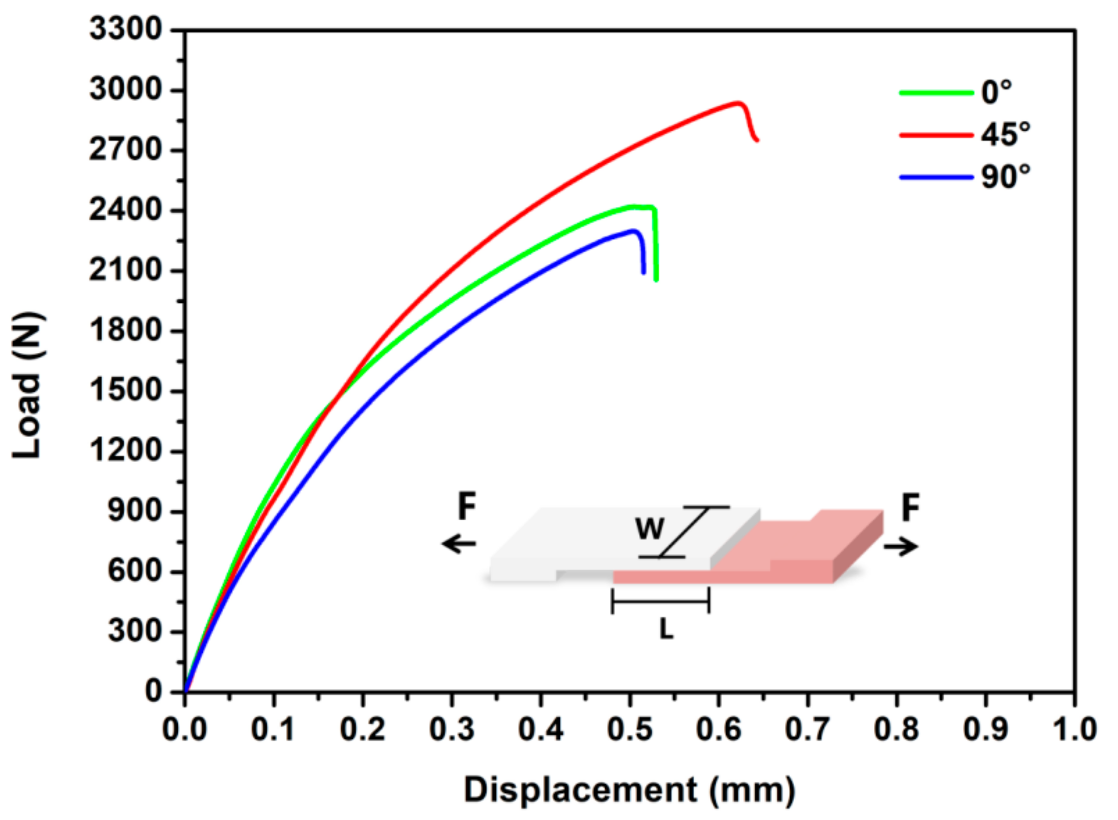
(2)
Numerical calculation. We calculate the deviation of the applied stresses between the W3 and L5 layers at the serration strain on each stress-strain curve and the interface shear strength along the corresponding tensile direction. The results are listed in Table 3. It can be seen that all the deviations are larger than the interface shear strength values. Therefore, it is believed that the interface fracture forms when the W3/L5 laminated composite is tensioned to the serration strain along each tensile direction. When increasing the stress, the interface becomes the source of prior fracture, leading to the deterioration of ultimate strength and elongation-to-failure.
As mentioned above, the yield strength of the laminated composite is perfectly satisfied by the ROM law, but it does not work to the ultimate strength and elongation-to-failure. The low interface shear strength results in poor metallurgical interface bonding. With the development of tension, the interface fracture forms, and it induces the prior fracture of the W3/L5 laminated composite, worsening its ultimate strength and elongation-to-failure.

4. Conclusions

In the present study, we designed a mixed texture with a closely orthotropic shape to ameliorate mechanical anisotropy through successfully fabricating the W3/L5 laminated composite via bimetal co-extrusion. Compared with the W3 and L5 alloys, the W3/L5 laminated composite displayed a better mechanical isotropy, detected by similar deformation behaviors (basal slip dominated the tensile deformation) in different tensile directions. The yield strength of the laminated composite perfectly coincided with the ROM law. However, poor metallurgical interface bonding resulted in worse ultimate strength and elongation-to-failure, due to rich O element voids on the interface inducing the prior interface fracture. Therefore, we believe that improving interface bonding is urgently needed in future works; controlling co-extrusion parameters or implementing a suitable heat treatment after extrusion can lead to improved mechanical properties of laminated composites with a mixed texture.

Author Contributions

Conceptualization, H.Z. and Q.W.; methodology, H.Z. and Q.W.; validation, H.Z., Q.W., G.X. and Z.J.; formal analysis, H.Z. and Q.W.; investigation, H.Z.; resources, Q.W.; data curation, H.Z. and Q.W.; writing—original draft preparation, H.Z. and Q.W.; writing—review and editing, Q.W., B.J., Y.S. and Z.J.; supervision, Q.W., B.J. and Z.J.; project administration, B.J.; funding acquisition, B.J. All authors have read and agreed to the published version of the manuscript.

Funding

This research was funded by the National Key Research and Development Program of China (U1764253) and the Chongqing Scientific & Technological Talents Program (KJXX2017002).

Data Availability Statement

Not applicable.

Conflicts of Interest

The authors declare no conflict of interest.

References

  1. Wang, Q.; Jiang, B.; Chen, D.; Jin, Z.; Zhao, L.; Yang, Q.; Huang, G.; Pan, F. Strategies for enhancing the room-temperature stretch formability of magnesium alloy sheets: A review. J. Mater. Sci. 2021, 56, 12965–12998. [Google Scholar] [CrossRef]
  2. Lee, T.; Kwak, B.J.; Yu, J.; Lee, J.H.; Noh, Y.; Moon, Y.H. Deep-learning approach to predict a severe plastic anisotropy of caliber-rolled Mg alloy. Mater. Lett. 2020, 269, 127652. [Google Scholar] [CrossRef]
  3. Li, D.; Le, Q.; Li, X.; Wang, P.; Liao, Q.; Zhou, X.; Hu, C. The microstructure evolution and mechanical anisotropy of extruded Mg-2Zn-0.4Ce-0.4Mn alloy tube during tension in different directions. J. Alloys Compd. 2021, 873, 159829. [Google Scholar] [CrossRef]
  4. Hong, S.-G.; Park, S.H.; Lee, C.S. Role of {10–12} twinning characteristics in the deformation behavior of a polycrystalline magnesium alloy. Acta Mater. 2010, 58, 5873–5885. [Google Scholar] [CrossRef]
  5. Wang, Q.; Shen, Y.; Jiang, B.; Tang, A.; Chai, Y.; Song, J.; Yang, T.; Huang, G.; Pan, F. A good balance between ductility and stretch formability of dilute Mg-Sn-Y sheet at room temperature. Mater. Sci. Eng. A 2018, 736, 404–416. [Google Scholar] [CrossRef]
  6. Rakshith, M.; Seenuvasaperumal, P. Review on the effect of different processing techniques on the microstructure and mechanical behaviour of AZ31 Magnesium alloy. J. Magnes. Alloys 2021, 9, 1692–1714. [Google Scholar]
  7. Pei, R.; Korte-Kerzel, S.; Al-Samman, T. Superior microstructure and mechanical properties of a next-generation AZX310 magnesium sheet alloy. Mater. Sci. Eng. A 2019, 763, 138112. [Google Scholar] [CrossRef]
  8. Chai, Y.; Shan, L.; Jiang, B.; Yang, H.; He, C.; Hao, W.; He, J.; Yang, Q.; Yuan, M.; Pan, F. Ameliorating mechanical properties and reducing anisotropy of as-extruded Mg-1.0Sn-0.5Ca alloy via Al addition. Prog. Nat. Sci. 2021, 31, 722–730. [Google Scholar] [CrossRef]
  9. Yang, Z.Q.; Ma, A.B.; Xu, B.Q.; Jiang, J.H.; Sun, J.P. Development of a high-strength Mg–11Gd–2Ag (wt%) alloy sheet with extra-low anisotropy. Mater. Sci. Eng. A 2021, 811, 141084. [Google Scholar] [CrossRef]
  10. Hoseini-Athar, M.M.; Mahmudi, R.; Prasath Babu, R.; Hedström, P. Tailoring the texture of an extruded Mg sheet through constrained groove pressing for achieving low mechanical anisotropy and high yield strength. Scr. Mater. 2020, 186, 253–258. [Google Scholar] [CrossRef]
  11. Xu, J.; Jiang, B.; Kang, Y.; Zhao, J.; Zhang, W.; Zheng, K.; Pan, F. Tailoring microstructure and texture of Mg-3Al-1Zn alloy sheets through curve extrusion process for achieving low planar anisotropy. J. Mater. Sci. Technol. 2022, 113, 48–60. [Google Scholar] [CrossRef]
  12. He, J.; Jiang, B.; Yang, Q.; Xu, J.; Liu, B.; Pan, F. Improved the anisotropy of extruded Mg-3Li-3Al-Zn alloy sheet by presetting grain re-orientation and subsequent annealing. J. Alloys Compd. 2016, 676, 64–73. [Google Scholar] [CrossRef]
  13. Li, X.; Jiang, B.; He, J.; Zhang, J.; Jiang, Z.; Liu, B.; Pan, F. Improvement of planar isotropy, mechanical properties and corrosion resistance of extruded Mg-3Al-1Zn alloy sheet by special grain re-orientation. J. Alloys Compd. 2017, 721, 106–117. [Google Scholar] [CrossRef]
  14. Feng, B.; Xin, Y.; Hong, R.; Yu, H.; Wu, Y.; Liu, Q. The effect of architecture on the mechanical properties of Mg-3Al-1Zn rods containing hard Al alloy cores. Scr. Mater. 2015, 98, 56–59. [Google Scholar] [CrossRef]
  15. Feng, B.; Xin, Y.; Guo, F.; Yu, H.; Wu, Y.; Liu, Q. Compressive mechanical behavior of Al/Mg composite rods with different types of Al sleeve. Acta Mater. 2016, 120, 379–390. [Google Scholar] [CrossRef]
  16. Feng, B.; Sun, Z.; Wu, Y.; Feng, X.; Wang, J.; Zheng, K. Microstructure and mechanical behavior of Mg ZK60/Al 1100 composite plates fabricated by co-extrusion. J. Alloys Compd. 2020, 842, 155676. [Google Scholar] [CrossRef]
  17. Wang, Q.; Song, Y.; Jiang, B.; Fu, J.; Tang, A.; Sheng, H.; Song, J.; Zhang, D.; Jiang, Z.; Huang, G.; et al. Fabrication of Mg/Mg composite with sleeve-core structure and its effect on room-temperature yield asymmetry via bimetal casting-co-extrusion. Mater. Sci. Eng. A 2020, 769, 138476. [Google Scholar] [CrossRef]
  18. Zhao, K.N.; Xu, D.X.; Li, H.X.; Zhang, J.S.; Chen, D.L. Microstructure and mechanical properties of Mg/Mg bimetal composites fabricated by hot-pressing diffusion and co-extrusion. Mater. Sci. Eng. A 2019, 764, 138194. [Google Scholar] [CrossRef]
  19. Meng, Y.; Zhang, H.; Lin, B.; Wang, L.; Fan, J.; Lu, L.; Zhou, X.; Huang, H.; Zhang, S.; Roven, H.J. Microstructure and mechanical properties of the AZ31/GW103K bimetal composite rods fabricated by co-extrusion. Mater. Sci. Eng. A 2022, 833, 142578. [Google Scholar] [CrossRef]
  20. Yang, W.; Quan, G.F.; Ji, B.; Wan, Y.F.; Zhou, H.; Zheng, J.; Yin, D.D. Effect of Y content and equal channel angular pressing on the microstructure, texture and mechanical property of extruded Mg-Y alloys. J. Magnes. Alloys 2022, 10, 195–208. [Google Scholar] [CrossRef]
  21. Zeng, Y.; Jiang, B.; Yang, Q.R.; Quan, G.F.; He, J.J.; Jiang, Z.T.; Pan, F.S. Effect of Li content on microstructure, texture and mechanical behaviors of the as-extruded Mg-Li sheets. Mater. Sci. Eng. A 2017, 700, 59–65. [Google Scholar] [CrossRef]
  22. Tan, H.F.; Zhang, B.; Luo, X.M.; Sun, X.D.; Zhang, G.P. Strain rate dependent tensile plasticity of ultrafine-grained Cu/Ni laminated composites. Mater. Sci. Eng. A 2014, 609, 318–322. [Google Scholar] [CrossRef]
  23. Wu, Y.; Feng, B.; Xin, Y.; Hong, R.; Yu, H.; Liu, Q. Microstructure and mechanical behavior of a Mg AZ31/Al 7050 laminate composite fabricated by extrusion. Mater. Sci. Eng. A 2015, 640, 454–459. [Google Scholar] [CrossRef]
  24. Liu, J.C.; Hu, J.; Nie, X.Y.; Li, H.X.; Du, Q.; Zhang, J.S.; Zhuang, L.Z. The interface bonding mechanism and related mechanical properties of Mg/Al compound materials fabricated by insert molding. Mater. Sci. Eng. A 2015, 635, 70–76. [Google Scholar] [CrossRef]
  25. Wu, H.; Wang, T.; Wu, R.; Hou, L.; Zhang, J.; Li, X.; Zhang, M. Effects of Annealing Process on the Interface of Alternate α/β Mg-Li Composite Sheets Prepared by Accumulative Roll Bonding. J. Mater. Process. Technol. 2018, 254, 265–276. [Google Scholar] [CrossRef]
  26. Zhao, K.N.; Liu, J.C.; Nie, X.Y.; Li, Y.; Li, H.X.; Du, Q.; Zhuang, L.Z.; Zhang, J.S. Interface formation in magnesium–magnesium bimetal composites fabricated by insert molding method. Mater. Des. 2016, 91, 122–131. [Google Scholar] [CrossRef]
  27. Wang, Q.; Shen, Y.; Jiang, B.; Tang, A.; Song, J.; Jiang, Z.; Yang, T.; Huang, G.; Pan, F. Enhanced stretch formability at room temperature for Mg-Al-Zn/Mg-Y laminated composite via porthole die extrusion. Mater. Sci. Eng. A 2018, 731, 184–194. [Google Scholar] [CrossRef]
  28. Zhao, K.N.; Li, H.X.; Luo, J.R.; Liu, Y.J.; Du, Q.; Zhang, J.S. Interfacial bonding mechanism and mechanical properties of novel AZ31/WE43 bimetal composites fabricated by insert molding method. J. Alloys Compd. 2017, 729, 344–353. [Google Scholar] [CrossRef]
  29. Zhao, K.N.; Xu, D.X.; Li, H.X.; Wang, J.; Ma, Y.Z.; Zhang, J.S. Fabrication, microstructure, and properties of interface-reinforced Mg/Mg bimetal composites by long-period stacking ordered structures. J. Alloys Compd. 2020, 816, 152526. [Google Scholar] [CrossRef]
Figure 1. (a) Preparation of cast Mg-3Y/Mg-5Li (W3/L5) composite billet; (b) bimetal co-extrusion process; (c) SEM image of W3/L5 laminated composite, where ND and ED represent the normal and extrusion directions, respectively.
Metals 12 00637 g001
Figure 2. Schematic diagrams of tensile sample (a) and shear sample (b) in W3/L5 laminated composite.
Metals 12 00637 g002
Figure 3. (a,c) OM images of W3 and L5 layers in W3/L5 laminated composite, respectively; (b,d) EBSD results including IPF and micro-texture maps of W3 and L5 layers in W3/L5 laminated composite, respectively.
Metals 12 00637 g003
Figure 4. True tensile stress-strain curves of W3 layer (a), L5 layer (b) and W3/L5 laminated composite (c) at RT along 0°, 45° and 90°; (d) view of high magnification from black frame in (c).
Metals 12 00637 g004
Figure 5. Schmid factor (SF) maps for basal slip of W3 (ac) and L5 (ik) layers and SF maps for {10–12} extension twinning of W3 (eg) and L5 (mo) layers applied to tension along 0°, 45° and 90°, respectively; average SF values for basal slip of W3 (d) and L5 (h) layers and average SF values for {10–12} extension twinning of W3 (l) and L5 (p) layers, respectively.
Metals 12 00637 g005
Figure 6. SFs for basal slip (a) and {10–12} extension twinning (b) of W3 layer, L5 layer and W3/L5 laminated composite along different tensile directions, covering the angles between 0° and 180° away from the ED to the TD.
Metals 12 00637 g006
Figure 7. (a) SEM image of the interface of W3/L5 laminated composite including many voids labeled by red arrows; (b) high magnification view from black frame A in (a); (c) SEM mapping from yellow frame in (b); (d) high magnification view from black frame B in (a); (e) SEM line scanning from yellow line in (d).
Metals 12 00637 g007
Figure 8. Load-displacement curves of W3/L5 laminated composite applied to shear force along 0°, 45° and 90°.
Metals 12 00637 g008
Figure 9. SEM images showing cross (a,d,g) and longitudinal (b,e,h) sections of fracture samples (for W3/L5 laminated composite) applied to tension along 0°, 45° and 90°, respectively; (c,f,i) views of high magnification from yellow frames in (b,e,h), respectively.
Metals 12 00637 g009
Table 1. Experimented and predicted tensile properties of W3 layer, L5 layer and W3/L5 laminated composite along 0°, 45° and 90° at RT.
SampleYield Strength (MPa)Ultimate Strength (MPa)Elongation-to-Failure (%)
45°90°45°90°45°90°
W3/L5 (W3)161.4 ± 3.2196.3 ± 2.8205.5 ± 2.2380.1 ± 4.5399.5 ± 3.1417.1 ± 5.635.8 ± 1.225.8 ± 0.824.6 ± 0.9
W3/L5 (L5)133.8 ± 2.1104.3 ± 2.3132.7 ± 2.8254.2 ± 3.1247.9 ± 4.5259.1 ± 3.924.5 ± 0.836.1 ± 0.725.7 ± 1.1
W3/L5 Exp.153.8 ± 3.3148.4 ± 2.6162.8 ± 2.8298.4 ± 4.2286.9 ± 3.8286.9 ± 3.117.2 ± 0.718.6 ± 0.916.9 ± 0.8
W3/L5 Pre.147.6 ± 2.7150.3 ± 2.5169.1 ± 2.5317.2 ± 3.8323.4 ± 3.8338.1 ± 4.8---
∆ *6.2 ± 3.0−1.9 ± 2.6−6.3 ± 2.6−18.8 ± 4.1−36.5 ± 3.8−51.2 ± 3.9---
* ∆ = W3/L5 Exp. − W3/L5 Pre.
Table 2. Interface shear strength values of W3/L5 laminated composite along 0°, 45° and 90° at RT.
SampleLoad (N)Contact Area (mm2)Shear Strength (MPa)
W3/L5-0°24205.12 × 10.0646.98
W3/L5-45°29354.98 × 10.0358.75
W3/L5-90°22985.05 × 9.9845.59
Table 3. Deviations of applied stresses between W3 and L5 layers at the serration strain on each stress-strain curve of the W3/L5 laminated composite along 0°, 45° and 90° at RT.
Tensile DirectionSerration StrainStress (MPa)∆ * (MPa)
W3L5
0.12027521758
45°0.068263155108
90°0.100304187117
* ∆ = Stress (W3) − Stress (L5).
Publisher’s Note: MDPI stays neutral with regard to jurisdictional claims in published maps and institutional affiliations.

