Article

Experimental Modeling of the Bifurcation Set Equation of the Chip-Splitting Catastrophe in Symmetrical Straight Double-Edged Cutting

School of Mechanical Science and Engineering, Huazhong University of Science and Technology, Wuhan 430074, China
*
Author to whom correspondence should be addressed.
Submission received: 5 April 2022 / Revised: 17 May 2022 / Accepted: 20 May 2022 / Published: 22 May 2022

Abstract

:
The chip-splitting catastrophe (CSC) generated by symmetrical cutting with a straight double-edged tool will lead to a significant reduction in cutting force. This has enormous potential for energy-saving machining and for the design of energy efficient cutting tools. The premise of the utilization is to establish a mathematical model that can predict the critical conditions of CSC. However, no related literature has studied the prediction model of CSC. Therefore, this paper proposes an experimental method based on catastrophe theory to establish a model of CSC bifurcation set equations that can predict critical conditions. A total of 355 groups of experiments are conducted to observe the critical conditions of CSC in symmetrical straight double-edged cutting, and 22 groups of experimental data of the critical conditions were acquired. The modeling process is converted into the optimal solution of the function coefficient value when the mapping function from a set of actual control parameters to theoretical control parameters (u, v, w) is a linear function. The bifurcation set equation of CSC is established, which can predict CSC in the symmetrical cutting of a straight double-edged turning tool with any combination of edge angle and rake angle. With verification, it is found that the occurrence of CSC has obvious regularity, and the occurrence of CSC will lead to a maximum reduction of 64.68% in the specific cutting force. The predicted values of the critical cutting thickness for the CSC of the established equation are in good agreement with the experimental results (the average absolute error is 5.34%). This study lays the foundation for the energy-saving optimization of tool geometry and process parameters through the reasonable utilization of CSC.

1. Introduction

The chip-splitting catastrophe (CSC) is a kind of abrupt change in chip morphology, and it can often be observed when cutting with a double-edged tool under continuously changing technological (control) parameters. For example, when a straight double-edged tool with a cutting edge angle of 45° is used to symmetrically transverse feed an AISI 1045 steel disc workpiece at a specific spindle speed and feed rate, the following CSC can be observed. In the cutting process, when the cutting speed continuously reduces to a critical value, a single strip chip that remains intact will suddenly split from the middle. In this case, two strip chips are obtained, and they eventually flow out in two different directions [1].
Artificial chip splitting differs from cutting with multi-tooth cutting tools with chip-splitting structures, such as multi-facet drills [2], milling cutters [3], a dedicated cutting tool in the dry orbital drilling process [4] and in broaching [5], etc., in that artificial chip splitting is caused by the discontinuity of the cutting layout [6]. CSC, however, is generated by the inherent law of the cutting process, which belongs to the natural chip splitting [1]. Additionally, the cutting force caused by CSC is substantially reduced (the reduction is much larger than that of the artificial chip splitting) [7], which makes people aware of the considerable utilization potential of CSC in energy-saving machining and in the design of energy-efficient cutting tools. Therefore, a systematic experimental investigation of the critical conditions and the modeling technique of CSC in double-edged cutting is significant to promote the development of metal cutting theory and energy conservation and discharge reduction technology. Meanwhile, it is conducive to solving practical engineering problems, such as the excessive deformation of the workpiece [8], tool wear, and other issues produced by the superfluous cutting force in the processing of numerous thin-walled parts [9], crucial parts [10], and aircraft landing gear in the petroleum and aviation industries.
For a long time, a lot of research efforts have been devoted to studying the rules of change in chip morphology and the modeling techniques under different processing conditions, and fruitful achievements have been achieved. For instance, through experimental observations of the chip morphology in the machining of EN16MnCr5 steel with a straight double-edged tool, Monkova et al. [11] found that the larger the cutting thickness and the edge inclination angle, the longer the chip. Polvorosa et al. [12] compared the tool wear with its corresponding chip morphology when turning Alloy 718 with cemented carbide inserts. They pointed out that tool wear can be predicted by observing the chip morphology under specific processing conditions. During the turning experiment of AISI 1045 steel, Dilip Jerold [13] reported that using cryogenic carbon dioxide as the cutting fluid can reduce the chip thickness and decrease the chip compression ratio and cutting force, thus achieving a better surface quality of the workpiece. Based on the experimental data, Patwari et al. [14] developed a chip serration frequency prediction model for the high-speed end milling of S45C steel using TiN inserts, and the prediction accuracy of the model reached 95%. Under other operating conditions, such as the step shoulder down-milling of Ti-6Al-4V [15], the combination of friction drilling and a tapping process for making ‘nutless’ bolted joints [16], and the orthogonal cutting of hardened low alloy steel 51CrV4 + Q [17], many significant research findings regarding chip morphology have been obtained. Unfortunately, these findings all assumed fixed process parameters and did not involve the sudden change of the chip morphology, so they cannot be applied to the modeling of CSC.
The research on CSC began 50 years ago. In an experiment with a symmetrical V-shaped double-edge cutting tool in a V-trough for a right-angle fixed-width cutting workpiece, Luk [18] observed that, when the ratio between the incomplete deep cut thickness (the second cut) and the complete deep cut thickness (the first cut) is gradually reduced to less than 0.1, CSC will occur during the second cutting. Based on this, Yamamoto and Nakamura [19] further experimentally studied CSC by using straight double-edged V-shaped tools. A combination of two different cutting edge angles and three different rake angles was applied to the plane brass blocks with five different widths, thus achieving six sets of CSC critical conditions with the same rake angle. Further, a simple mechanical model was established in the investigation to qualitatively explain the mechanism of CSC. It was identified that the specific cutting force in CSC was up to 30% lower than that in no CSC. To examine the influence of CSC on the process parameter design, Shi [20] conducted cutting experiments by traversing low-carbon steel disc workpieces with a high-speed steel straight double-edged tool under different cutting edge angles. Meanwhile, both the edge inclination angle and rake angle were maintained at 0. It was revealed that the cutting force decreased greatly before and after CSC, with a maximum reduction of up to 40.55%. Additionally, the research found that CSC is more likely to occur when the cutting edge angle becomes larger and the rake angle and cutting thickness become smaller within a certain range of the process parameters. Using the same type of tools with a non-zero cutting edge inclination angle and a rake angle to perform similar experiments, Xu et al. [21] discovered that CSC lowered the maximum specific cutting force by 51.23%. They also define the critical cutting thickness of the CSC. Rezayi Khoshdarregi and Altintas [22] also noticed CSC in thread-turning experiments with a V-profile insert, but they did not conduct further investigation into this. Zhu et al. [23] proposed a new combined constitutive model, using the finite element method to simulate the chip morphology after CSC, but a mathematical model of the critical cutting conditions for CSC has not been established.
Obviously, the above-mentioned studies on CSC are all in the preliminary stage of the experimental observation and qualitative explanation of the CSC mechanism. Currently, no systematic experiments have been conducted to obtain complete experimental data of CSC under critical conditions, nor has a mathematical model of CSC been established based on the existing experimental data to realize and predict the critical conditions for CSC accurately. One of the main reasons for this is that the existing studies exploit the calculus approach to research the continuous and gradual changing phenomena of metal cutting [24]. However, this approach is not suitable for studying the non-continuous and abruptly changing cutting catastrophe phenomenon exhibited by CSC. The mathematical tool suitable for modeling the cutting catastrophe phenomenon is the catastrophe theory, which was established in 1970s [25]. It adopts seven standard catastrophe mathematical models that exploit the potential function, manifold surface equation, and bifurcation set equation (to predict the critical conditions of catastrophe) to describe the catastrophe phenomenon in which the control variables change continuously [26]. It provides two methods for establishing mathematical models of CSC, including the theoretical modeling method and the experimental modeling method. So far, catastrophe theory and its two recommended modeling methods have been successfully applied to modeling, controlling, and utilizing the catastrophe phenomena in different fields [27], and many achievements have occurred.
In the field of mechanical engineering, the theoretical modeling methods based on catastrophe theory have been successfully applied to many catastrophe phenomena, such as shear angle catastrophe [28], friction coefficient catastrophe [29], chip flow angle catastrophe when cutting with a double-edged tool with an edge inclination angle of 0 [30,31] or an arbitrary edge inclination angle [32], etc. In the experimental modeling research based on experimental data, Luo [33] assumed that a linear function existed between the actual control variables of the abrupt change of the tool wear state and the theoretical control variables of the cusp catastrophe [25]. Based on this assumption, the coefficients of the functions were fitted according to the experimental data, and the cusp catastrophe model of tool wear state catastrophe was established. This model obtained a prediction error of less than 10%. Unfortunately, the research on CSC is mainly concentrated in the experimental observation stage; there have not been any reports on the modeling and prediction of the CSC exercising catastrophe.
In this study, the complete data of CSC under critical conditions are obtained by conducting systematic experiments on CSC. According to the experimental results, based on the standard bifurcation set equation of the swallowtail catastrophe [25] from catastrophe theory, this paper assumes that the mapping from the actual control variables of CSC to the theoretical control variables of the swallowtail catastrophe is a linear function. Then, 12 coefficients of the function are fitted by using a modern optimization technique. Meanwhile, the bifurcation set equation of CSC suitable for straight double-edged tools with any combination of cutting edge angles and rake angles is established. Through actual cutting experiments, the effectiveness of the bifurcation set equation is verified, and an accurate prediction of the critical cutting thickness of CSC is achieved.

2. Experimental Investigation and Acquisition of Experimental Data under Critical Conditions of CSC

The material used in the experiments was a normalized medium carbon steel AISI 1045. The chemical composition of the batch in weight (%) is listed in Table 1 [34].
Transverse turning of the discal workpiece with a double-edged tool is shown in Figure 1, where θ is the cutting edge angle, γ0 is the rake angle, ac is the cutting thickness, f is the cutting feed, aw is the cutting width, and λ s is the tool cutting edge inclination angle. Ps, Pr, and P0 are the cutting plane, reference plane, and orthogonal plane, respectively.
The approach for shooting and analyzing the three-round chip shape video was exploited for the high speed steel (HSS) straight double-edged tool to transversely feed the AISI 1045 steel disc workpieces. In this way, whether CSC occurs under a given set of cutting conditions can be examined, and the experimental data of CSC under the critical conditions can be obtained, including θ, γ0, and ac during CSC. Meanwhile, the three-dimensional dynamic cutting force can be measured.

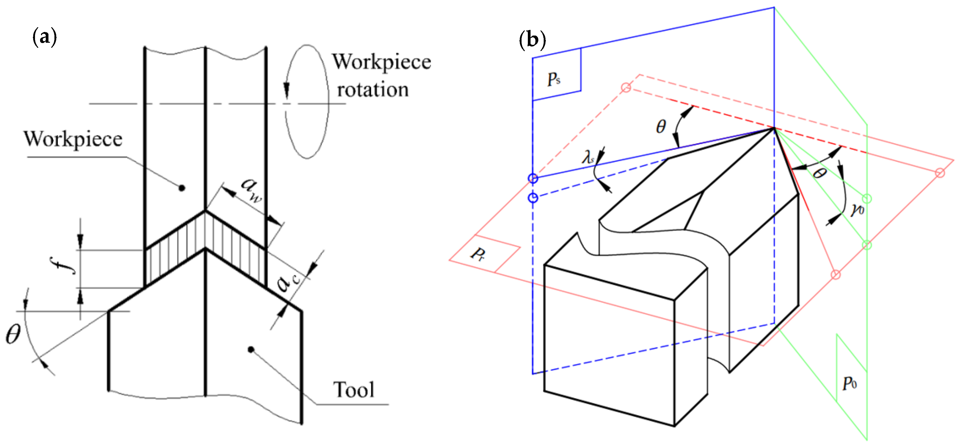
2.1. Experimental Design

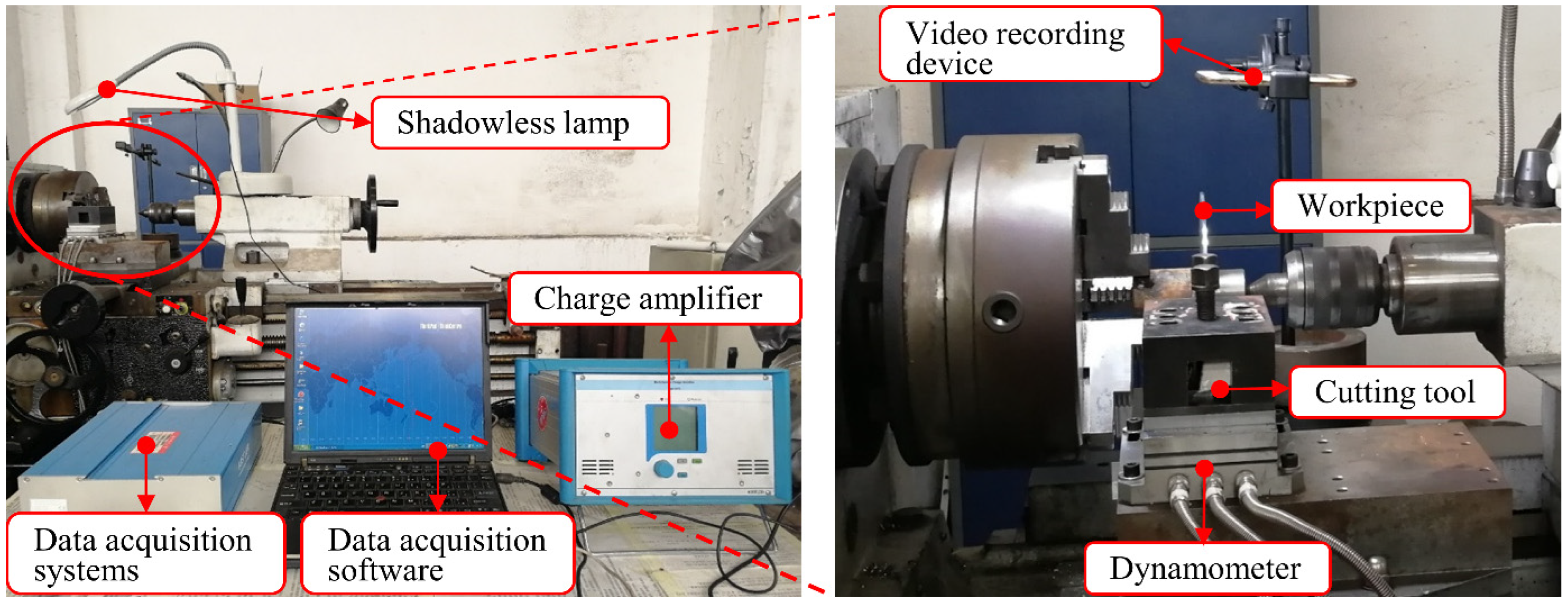
2.1.1. Experimental Devices

The experiment was conducted on a CW6163E precision (Dalian Machine Tool Group, Dalian, China) lathe equipped with a Yaskawa-A1000 inverter (YASKAWA Electric Corporation, Kitakyushu, Japan). As shown in Figure 2, the experimental platform consisted of a disc workpiece, a tool, a video recording device, and a Kistler turning force measuring system. Specifically, the disc workpiece has a diameter of 180 mm and a thickness of b (See Table 2). The tolerance values for the radial runout and end runout of the disc workpieces are set at no more than 0.05 mm. It was clamped between the scroll chuck and the tailstock; the tool was a self-made straight double-edged tool with a cutting edge angle θ and a rake angle γ0. The tool holder was horizontally mounted and perpendicular to the workpiece axis to ensure that the corner passed through the spindle rotation center; the video recording device was an iPhone 6 mobile phone (Apple Inc., Cupertino, CA, USA) with a slow-motion recording function, and it was fixed by a bracket placed on the machine’s cross slide carriage at a guaranteed level; the Kistler turning force measurement system consisted of a Kistler 9257A three-dimensional force gauge (Kistler Group, Winterthur, Switzerland), a Kistler 5070 charge amplifier (Kistler Group, Winterthur, Switzerland), a Kistler 5697 data acquisition system (Kistler Group, Winterthur, Switzerland), and DynoWare data analysis software (Type 2825A-02, Kistler Group, Winterthur, Switzerland).

2.1.2. Experimental Conditions and Related Instructions

Dry cutting was adopted to facilitate the observation and video shooting of the chip morphology. A low cutting speed (V = 5 m/min) was used to avoid the formation of built-up edges [35]. It is also convenient to observe the occurrence and change law of CSC by using a lower cutting speed to record the chip flow video. Similarly, low speed is often used in processing operations such as thread turning, planning, and broaching [5].
In each of the cutting experiments, the average value of the diameter of the workpiece before and after cutting was taken as the effective workpiece diameter to the calculated cutting speed. The frequency was also dynamically adjusted to keep the speed of the spindle of the machine tool constant so as to ensure that the change of the workpiece diameter would not cause large fluctuations in the cutting speed.
For a convenient comparison of the experimental results, the cutting edge inclination angle λs of all the tools in the experiment was set to 5°. Additionally, the cutting width aw of the cutting edges of all the tools in the experiment was uniformly set to 3 mm. In this way, we can get the following relationship [21]:
b = 2awcosθ = 6cosθ
Among them, b is the workpiece thickness, and its unit is mm; θ is the edge angle, and its unit is deg. That is, the thickness b of the workpiece can be calculated and determined according to the edge angle θ set in the experiment.
During the experiment, the adjustment of the cutting thickness ac was realized by changing the transverse feed f of the machine tool, i.e.,
f = ac/cosθ
In the formula, f represents the transverse feed, and its unit is mm/r; ac is the cutting thickness, and its unit is mm. As for the CW6163E precision lathe, the adjustment of f is graded, as is the adjustment of ac. Due to this, the critical cutting thickness and its boundary values can be obtained by the cutting experiment.
The grinding process of the experimental turning tool was completed on an MQ6025 universal tool grinder (a grinding head with three rotational degrees of freedom, Wuhan Machine Tool Co., Ltd., Wuhan, China) equipped with a universal clamp with three rotational degrees of freedom. The rotational angle resolution of the three degrees of freedom of the universal clamp and the grinding head are both 2°. In the process of grinding, the adjustment and calculation of the angle of the universal clamp and the grinding head are completed by the plane representation method proposed by Shi [1]. The measurement of the tool geometry is carried out by a Vernier universal angle ruler, and the angle measurement error is controlled within 2‘.

2.2. Methods and Processes for Obtaining Experimental Data of Critical Conditions

As mentioned above, three-round cutting experiments were conducted to obtain the critical conditions of CSC, namely, the cutting edge angle θ, rake angle γ0, and cutting thickness ac. The specific methods and processes are described as follows:
Based on the findings achieved by previous research on the regularity of the occurrence of CSC [1] and the related experimental results, as well as the minimum interval between the two consecutive feedings in the machine tool, the dichotomy method was applied to gradually reduce the interval of the control variable value and the experimental value interval used in the three-round experiments. In this way, the experimental data of CSC under the critical conditions were obtained.
After appropriate amplification, the interval ranges of the three control variables, i.e., the cutting edge angle θ, the rake angle γ0, and the cutting thickness ac, were set according to the range of the approximate critical conditions of CSC obtained in the prior experimental research. For θ (40°, 60°), γ0 (−20°, 0°), and ac (0.05 mm, 0.20 mm), the three control variables were assigned five, five, and four different values with equal spacing, respectively. In this way, the cutting edge angle θ was assigned 40°, 45°, 50°, 55°, and 60°; the rake angle γ0 was assigned −20°, −15°, −10°, −5°, and 0°; and the cutting thickness ac was assigned 0.05 mm, 0.10 mm, 0.15 mm, and 0.20 mm. The corresponding tool number used in the first round of experiments, the accessible machine feed value f, the actual cutting thickness ace0 calculated in reverse according to the f value, and the workpiece width b calculated according to the cutting edge angle θ are all listed in Table 2.
Twenty-five straight double-edged tools were ground (Figure 3) according to the full-factor experimental design method. Meanwhile, four cutting experiments were completed with each tool in the first round of the experiment. So, there were 100 experiments in total for all tools on the basis of which to observe and judge whether CSC occurred in the cutting process. If CSC is observed or not in the four experiments of a tool, it indicates that the critical cutting thickness is not within the value range, and the cutting experiment of the tool ends here; if CSC is observed or not in the four experiments of a tool, the difference between the two adjacent cutting thicknesses that lead to CSC is set as the new cutting thickness interval. The second round cutting experiment was carried out with this tool.
For the tools that need the second round of the cutting experiments, three-level values with equal spacing within the value range of the cutting thickness were used to accomplish another three experiments with the same method as in Step 3. The experiments for two of the three boundary-level values have already been completed, and only the experiment for the middle-level value needs to be conducted. The results of these three experiments will not be the same, that is, they will not all be chip-splitting, nor will they all be non-chip-spitting at the same time. Following the same method as in Step 3, the boundary value of the renewed cutting thickness was obtained. Additionally, one value was chosen from the boundary values as the critical cutting thickness of the tool, and then it was added to the list of the obtained critical conditions together with the corresponding edge angle θ and rake angle γ0.
After the completion of the second round of experiments, if any set of critical condition data in the critical condition list is the same as two of the three cutting parameters (i.e., ac and tγ0 or ac and θ) and the other tool angle parameters (i.e., θ or γ0) are different but adjacent, then the critical value of this angle parameter should be included within the two adjacent values. Here, “two of the three cutting parameters” are from a non-chip-splitting experiment in the previous two rounds of the experiments. This set of the critical condition data would be removed from the list of critical conditions, and the two values of this angle parameter would be used as the boundary values for the new value range. From this angle parameter, such as the rake angle γ0, three horizontal values (two of which are interval boundary values) were obtained based on the equal interval principle to grind out a new tool with intermediate horizontal values. The cutting thickness ac of the new tool is the critical cutting thickness obtained from the previous two tools. Then, a third round of the experiment was carried out with this new tool.
Based on the results obtained in the third round of the cutting experiments and following the same method mentioned above, a new boundary value for the rake angle γ0 can be obtained. Meanwhile, the greater absolute value of the two boundary values was taken to be the critical value of the rake angle γ0 (or cutting edge angle θ). This value, together with the corresponding cutting edge angle θ (or rake angle γ0) and cutting thickness ac, were added to the list of the obtained critical conditions.

2.3. Experimental Results

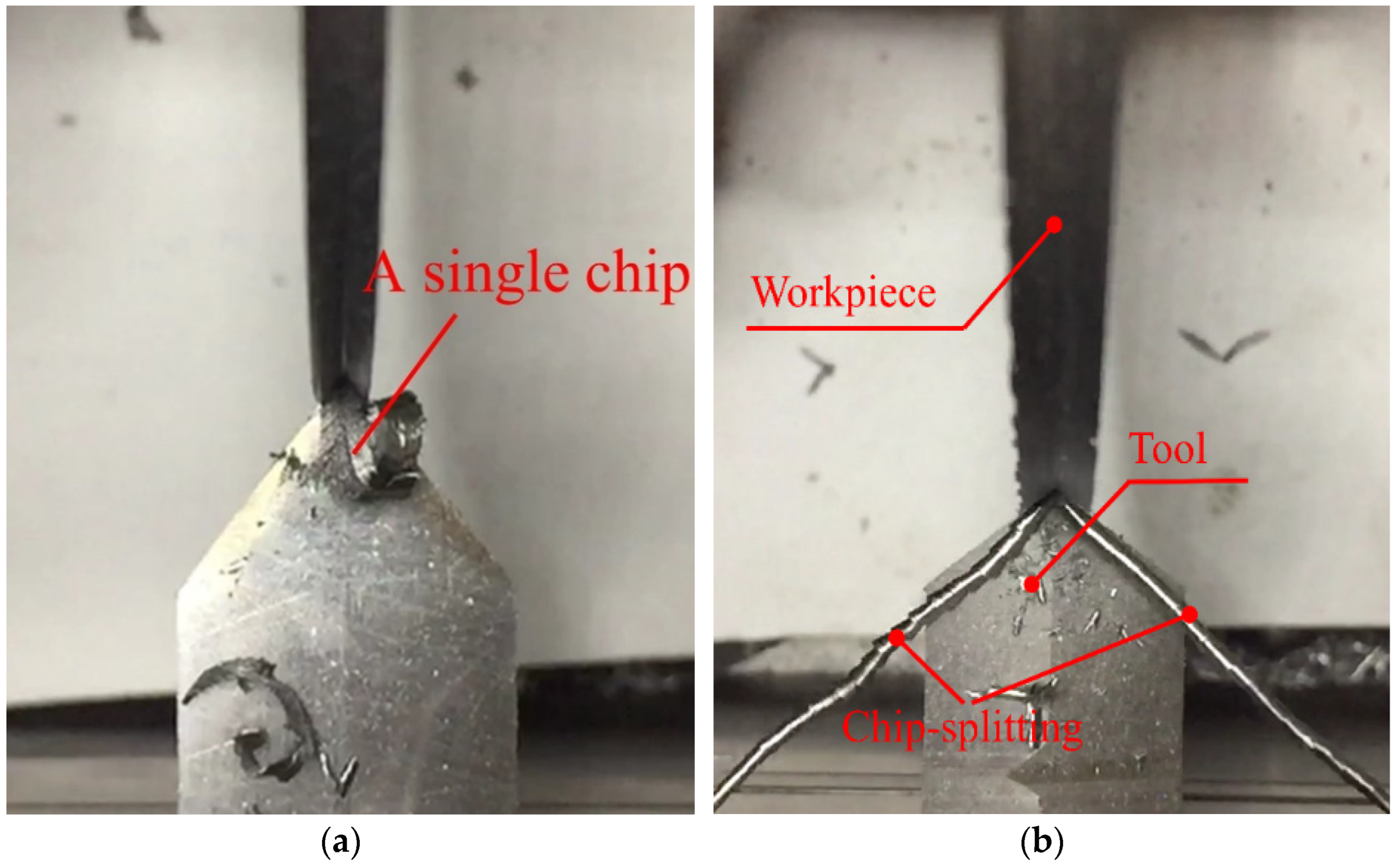
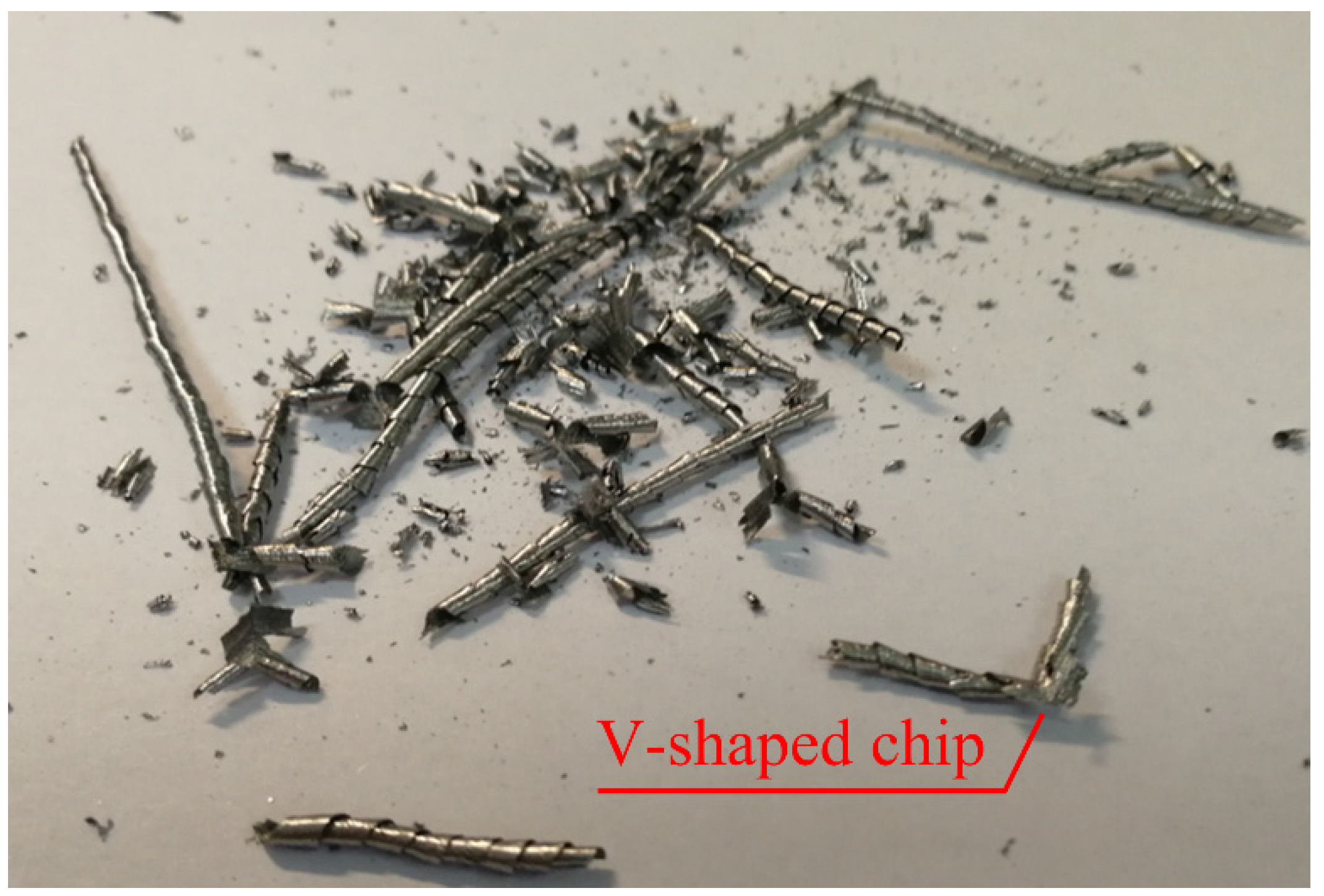
2.3.1. Observed Chip-Splitting Catastrophe Phenomenon

A total of 122 cutting experiments were performed successfully in three rounds, and CSC occurred in 41 experiments. A single chip without chip-splitting is shown in Figure 4a. It was also discovered that, when CSC occurred, each of the two cutting edges produced a chip, and the two chips were curled and discharged along the rake face in a V-shaped form in the direction of basic symmetry relative to the tooltip, as shown in Figure 4b. As shown in Figure 5, when its length reached a certain value, the chip would break naturally near the tooltip, and some of them remained V-shaped. This result is consistent with that of the previous research regarding the phenomenon of CSC [18].
To verify whether the occurrence of CSC is affected by accidental factors, some of the experiments were repeated one to three times. The results show that, within the experimental range, the chip-splitting and non-chip-splitting phenomena are repeatable and stable.

2.3.2. The Impact of Tool Geometry Parameters on CSC

It has been found that CSC is affected by both tool geometry parameters and cutting conditions—among these, the cutting edge angle and the rake angle need to be focused on. Firstly, in a frame with given process parameters, CSC is more likely to occur when the cutting edge angle becomes more immense. This is consistent with the research result of Shi [1]. The main reason for this phenomenon is probably that the larger the cutting edge angle, the higher the degree of deviation from the natural chip ejection direction. Thus, the severer the chip ejection interference, the more tremendous the force needed to maintain all the chips generated by the entire tool to be discharged as a whole. When this force leads to the tear in the middle of the chip, CSC occurs [23].
Secondly, within the range of the given process parameters, CSC is less likely to occur when cutting with a tool with a positive rake angle. However, when cutting with a tool with a negative rake angle, CSC is more likely to occur, and the probability of occurrence increases with the absolute value of the negative rake angle. This is consistent with the conclusion drawn by Luk [18], but it is not in perfect accord with the results observed in the cutting experiments of brass [19]. Yamamoto and Nakamura [19] reported that CSC is also likely to occur in the case of cutting with a tool with big positive rake angles. This indicates that the mechanism of CSC is worth further research.

2.3.3. Experimental Data of Critical Conditions of CSC

Following the aforementioned method, 22 groups of experimental data of CSC under the critical conditions for the symmetrical transverse cutting of AISI 1045 steel disc workpieces with straight double-edged tools were obtained. The data are listed in Table 3 and marked in bold characters. Table 3 also lists the boundary values of the control variables from the second and third rounds of the experiments corresponding to these 22 groups of experimental data. The data are presented above or below the row containing the data of the critical conditions, along with the cutting force and the chip-splitting states. It should be noted that the critical cutting thickness ace in Table 3 was obtained by reverse calculation according to the actual feed amount f and the cutting edge angle θ, and the precision of the values was kept to four places after the decimal.

2.3.4. Cutting Force before and after CSC

Based on the analysis of the cutting force data listed in Table 3, the following observations can be obtained:
(i) As for the same tool (the datum numbers in Table 3 are 2, 5, 8, 10, 13, 18, 20, and 22), its specific main cutting force and specific feed force during CSC were less than those without CSC. Specifically, the reduction in the specific main cutting force ranged from 24.67% (8) to 49.92% (13), while that of the specific feed force ranged from 14.01% (2) to 64.68% (18). Additionally, the tool with the datum number of 13 had the largest reduction (49.92%) in the specific main cutting force, and the tool with the datum number of 18 had the largest reduction (64.68%) in the specific feed force.
(ii) Given the same cutting edge angle and cutting thickness (the datum numbers in Table 3 are 1, 4, 6, 7, 9, 12, 14, 15, 19, and 21), the tools with a larger negative rake angle which were accompanied with CSC had a smaller specific main cutting force and specific feeding force than the tools with a smaller negative rake angle which were without CSC. As datum number 14 shows, compared to the tool with a smaller rake angle (−10°) and no CSC, the tool with a larger negative rake angle (−12°) and CSC had reductions in the specific main cutting force and the specific feed force of 40.95% and 59.05%, respectively.
(iii) Given the same rake angle and cutting thickness (the datum numbers in Table 3 are 3, 11, 16, and 17), the tools with a larger cutting edge angle and CSC had a smaller specific main cutting force and specific feed force than the tools with a smaller cutting edge angle and no CSC. As datum number 17 shows, compared to the tool with a smaller cutting edge angle (55°) and without CSC, the tool with a larger cutting edge angle (58°) and CSC had reductions in the specific main cutting force and the specific feeding force of 45.39% and 38.45%, respectively.
The above observations deviate from the common understanding of the cutting process, but they are consistent with the experimental results regarding CSC obtained by previous research [1]. Additionally, the observations again confirmed that CSC has great potential to be applied to the energy-saving design of tool geometry and cutting parameter optimizations.

3. Experimental Data-Based Model Establishment of the Bifurcation Set Equation of CSC

3.1. Modeling Principle and Method of the Bifurcation Set Equation in CSC

3.1.1. Experimental Modeling Method of Catastrophe Phenomena Based on Catastrophe Theory

According to catastrophe theory, any catastrophic phenomena can be described by a mathematical model consisting of a potential function (E) and a manifold surface (M) equation. E signifies a smooth potential function E (x, c) (x is the state variable and c is the control variable); A manifold M is obtained by making the first partial derivative of the potential function with respect to each state variable equal to 0, and a bifurcation set B is obtained by eliminating the state variables. The equation of the bifurcation set contains only the control variables and is capable of predicting the critical conditions of the catastrophe. The catastrophe phenomenon can be divided into seven types under the conditions of no more than four control variables and no more than two state variables. Meanwhile, the mathematical model of each catastrophe type can be converted into a standard form by a specific mapping function [36].
The mathematical model of catastrophe can be established by two methods, namely, the theoretical modeling method and the experimental modeling method. The experimental modeling method establishes a catastrophe mathematical model of standard form according to the number of independent actual change control variables and state variables observed in the experiments. It is assumed that a functional mapping relationship exists between the theoretical control variables and the actual control variables used in the standard mathematical model. Based on the experimental data with finite points on the bifurcation set curve/surface (B) or manifold surface (M), the coefficients of the mapping functions are calculated. Then, the complete mathematical model of the catastrophe is established. In this paper, the experimental modeling method is exploited to establish the bifurcation set equation of CSC when the straight double-edged tool symmetrically transverse feeds the AISI 1045 steel disc workpieces.

3.1.2. Modeling of the Bifurcation Set Equation of CSC Based on the Swallowtail Catastrophe

The previous experiments indicate that, when a straight double-edged tool symmetrically transverse feeds an AISI 1045 steel disc workpiece, the generation of CSC is affected by the cutting conditions that can be controlled artificially [1], such as the cutting edge angle θ, rake angle γ0, cutting edge inclination angle λs, cutting speed V, cutting width aw, and cutting thickness ac. To simplify the problem, based on the prior research experience and the results of the multi-round experiments, only the cutting edge angle θ, rake angle γ0, and cutting thickness ac are taken as control variables, whereas the CSC occurrence is taken as the state variable, and the remaining cutting conditions are fixed. The experimental modeling method described above is adopted to establish the model of the bifurcation set equation of CSC.
Catastrophe theory asserts that, when there are three control variables and one state variable, any actual catastrophic phenomenon belongs to the swallowtail catastrophe within the seven standard catastrophe types. Additionally, through topological equivalence transformation, i.e., the differential homomorphism [37], the mathematical model of the catastrophic phenomenon can be expressed in the following standard form, where u, v, and w are the theoretical control variables, and x is a theoretical state variable.
{ E : E = x 5 + u x 3 + v x 2 + w x M : 5 x 4 + 3 u x 2 + 2 v x + w = 0 B : 4096 u 6 + 46629 v 4 + 4096 w 3 = 0
Among them, E is the potential function, M is the manifold, and B is the bifurcation set.
Based on this, the process of establishing the bifurcation set equation model of CSC is as follows. First, it is assumed that a linear mapping function exists between the actual control variables and the theoretical control variables, and its coefficients need to be determined [38]. Then, a set of experimental data on the critical conditions of CSC is collected through systematic cutting experiments. Specifically, the coordinates of a series of points on the surface of the bifurcation set of CSC (referred to as the experimental points) are obtained, and the coordinates of the experimental points are substituted into the mapping function to obtain the coordinates of the corresponding theoretical points. By substituting the coordinates of these theoretical points into the bifurcation set equation B in Equation (3), a set of bifurcation set equations B’ expressed in experimental coordinates with undetermined coefficients is deduced. Subsequently, the squares of the left-hand polynomial of these equations B’ are summed, and a function indicated by the aforementioned undetermined coefficients and the coordinates of the experimental points is obtained. Taking this function as the objective function, the undetermined coefficients that make the objective function take the minimum value are obtained by the optimization method.

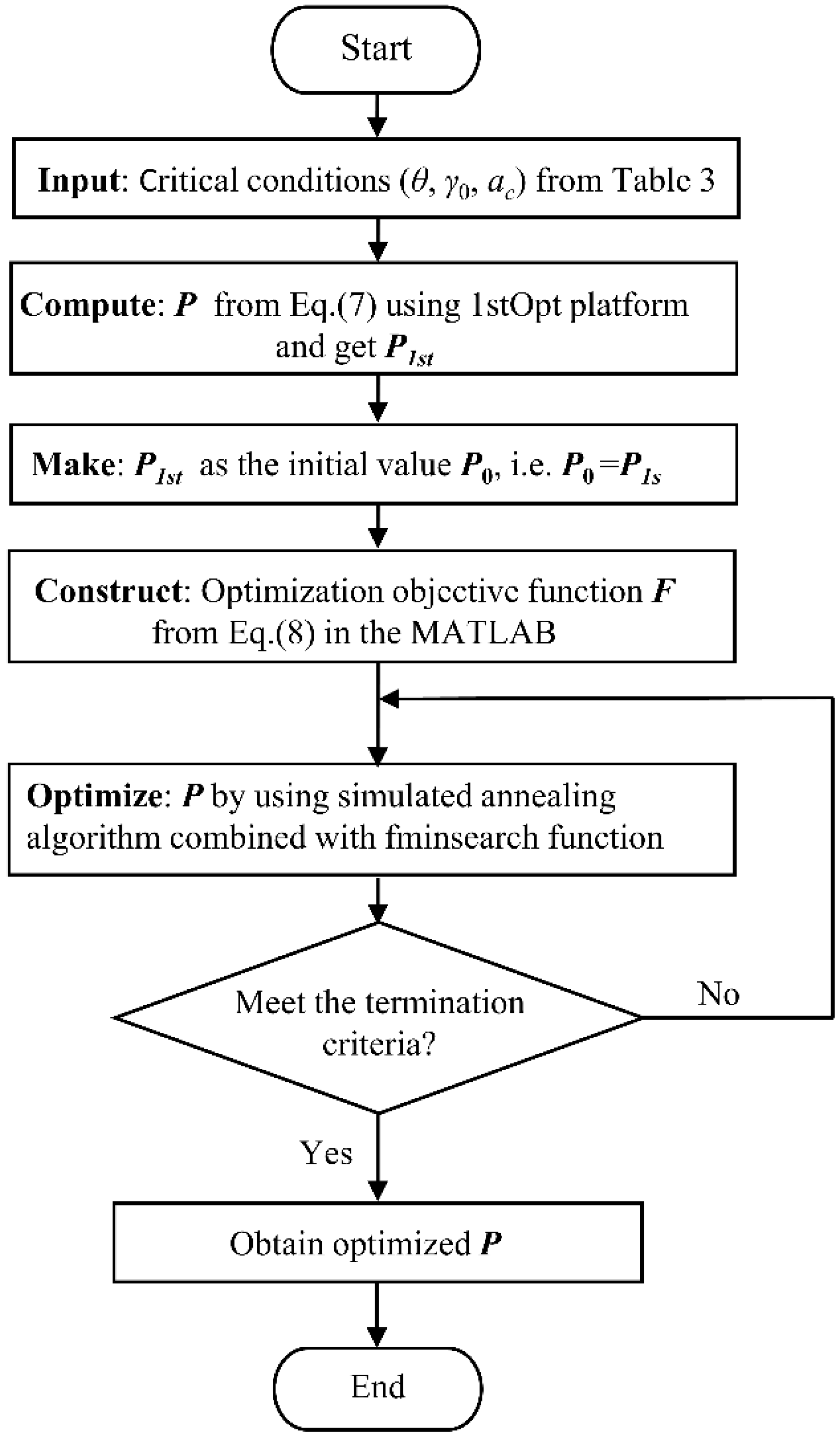
3.2. Mapping Function and Objective Optimization Function for Solving Its Coefficients

According to the relevant exposition of catastrophe theory, the mapping function between the cutting edge angle θ, the rake angle γ0, the cutting thickness ac, and the three theoretical control variables—u, v, and w—was considered as a set of linear functions [25], that is
u = f 1 θ , γ 0 , a c = p 1 + p 2 θ + p 3 γ 0 + p 4 a c = h 1 X , p 1 , p 2 , p 3 , p 4 v = f 2 θ , γ 0 , a c = p 5 + p 6 θ + p 7 γ 0 + p 8 a c = h 2 X , p 5 , p 6 , p 7 , p 8 w = f 3 θ , γ 0 , a c = p 9 + p 10 θ + p 11 γ 0 + p 12 a c = h 3 X , p 9 , p 10 , p 11 , p 12
where X = (θ, γ0, ac), p i R , i = 1, 2, 3, …, 12. By applying u, v, and w of Equation (4) to the bifurcation set equation of the standard swallowtail catastrophe mathematical model [38], i.e., equation B of Equation (1), we have:
4096 h 1 6 ( X , p 1 , p 2 , p 3 , p 4 ) + 46629 h 2 4 ( X , p 5 , p 6 , p 7 , p 8 ) + 4096 h 3 3 ( X , p 9 , p 10 , p 11 , p 12 ) = 0
The coordinates Xi of n practical points (here, n = 22) obtained by the experiments are Xi = (θi, γ0i, aci) (i = 1, 2, 3, …, n), instead of X in Equation (5). Additionally, n equations about coefficients p1, p2, p3, , p12 can be obtained:
4096 h 1 6 ( X i , p 1 , p 2 , p 3 , p 4 ) + 46629 h 2 4 ( X i , p 5 , p 6 , p 7 , p 8 ) + 4096 h 3 3 ( X i , p 9 , p 10 , p 11 , p 12 ) = 0
Let P = (p1, p2, p3, , p12), and denote the left side of Equation (6) as a new function of P and Xi. We have:
gi (P, Xi) = 0 (i = 1, 2, 3, …, n)
Then, an unconstrained optimization objective function can be constructed:
min P F = i = 1 n g i 2 ( P , X i )   ( i = 1 ,   2 ,   3 ,   ,   n )
The coefficients of the mapping function can be obtained by calculating P, which takes the minimum value of the objective function F of Equation (8).

3.3. Establishment of the Bifurcation Set Equation of CSC

The objective function of Equation (8) is solved by the Universal Global Optimization Algorithm (UGO) of the 1stOpt platform [39] and the optimization algorithm of MATLAB, which can be seen in Figure 6. Firstly, input the 22 groups of the critical conditions (θ, γ0, ac) from Table 3 and compute P from Equation (7) using the 1stOpt platform to obtain P1st. Then, P1st is optimized by MATLAB. Finally, the values of coefficient P (in five decimal places) of the obtained mapping function are listed in Table 4. The optimum error ranges from −9.35% to 9.35%, and the average error is −0.14%.
Applying the values into Equation (5), the CSC bifurcation set equation is established:
4096 ( 0.31745   +   0.00647 θ     0.01364 γ 0     1.84204 a c ) 6 + 46629 ( 0.01249   +   0.00027 θ     0.00034 γ 0     0.05225 a c ) 4 + 4096 ( 0.00955     0.00020 θ   +   0.00038 γ 0 + 0.04931 a c ) 3 = 0
where the unit of the rake angle γ0 and edge angle θ is deg, and the unit of the cutting thickness ac is mm.

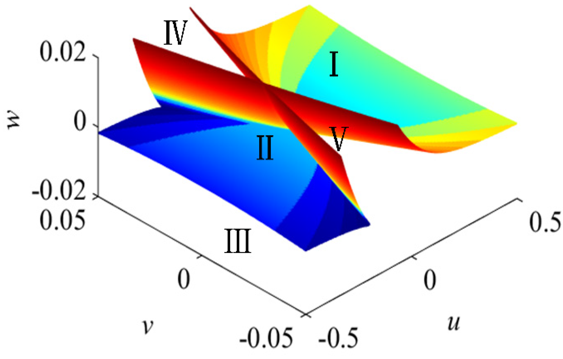
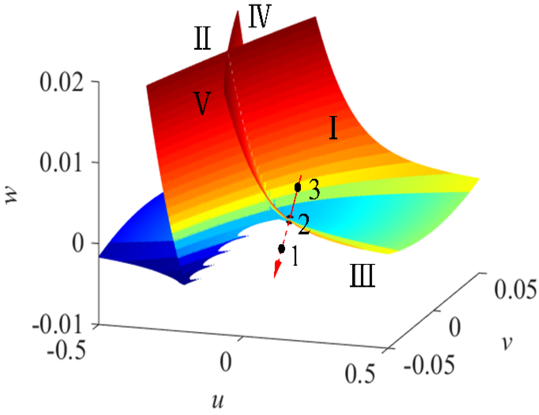
3.4. Analysis of the Bifurcation Set of CSC

According to the CSC bifurcation set equation and the experimental data of CSC under critical conditions, as well as the boundary values of CSC listed in Table 3, the theoretical control parameters u, v, and w can be calculated by using the mapping function from the actual control parameters to the theoretical control parameters. Additionally, as shown in Figure 7, the bifurcation set surface of the swallowtail catastrophe of CSC [40] can be drawn according to the range of values of u, v, and w. The surface is complex in the three-dimensional control space, and there is a set of critical points in the control space that causes the sudden change of the system. It is consistent with catastrophe theory that the bifurcation set surface divides the control space into five regions, namely, regions I, II, III, IV, and V [25], which is the set of boundary values corresponding to the critical condition data in Table 3. When the three control variables take different values, that is, when the change in the control point changes through the bifurcation set surface to different regions determined by the bifurcation set, the system state may change abruptly. This is because the number of stable equilibrium points of the potential function in each region is different [25].
As an example, Figure 8 illustrates the distribution of a theoretical critical point (point 2) and its two boundary value points (points 1 and 3) in the theoretical control space. Point 1 is located in region III, where the chips split; point 3 is located in region I, where the chips do not split; point 2 is located in the bifurcation set surface, and it is a critical point between the chip-splitting and the non-chip-splitting regions. According to the above analysis, when the theoretical point changes along the pathway 3→2→1 and enters region III from region I, the system changes from an equilibrium state (in which the minimum value of the potential function is relatively high and the chips do not split) to another equilibrium state (in which the minimum value of the potential function is relatively low and the chips split). CSC occurs.
In the application of the CSC bifurcation set surface, the values of the theoretical control variables (u, v, w) in the model can be determined according to the three actual control variables of tool edge angle, rake angle, and cutting thickness in the machining process. Three theoretical control variables determine the control point in the area of the bifurcation set surface and can then predict CSC in advance according to a certain trend of the actual control variable (for example, the cutting thickness changes monotonously from small to large). By determining the change path of the control point in the bifurcation set surface, the change way of CSC can also be predicted. People can also control CSC to occur in the direction we expect by changing the corresponding actual control variables. This method can not only explain the causes of CSC but also predict and control the occurrence of CSC. The latter is precisely the advantage of this study, which is not available in the research of previous studies [1,19].

4. Prediction Results of the Critical Conditions and the Experimental Verification of the Bifurcation Set Equation

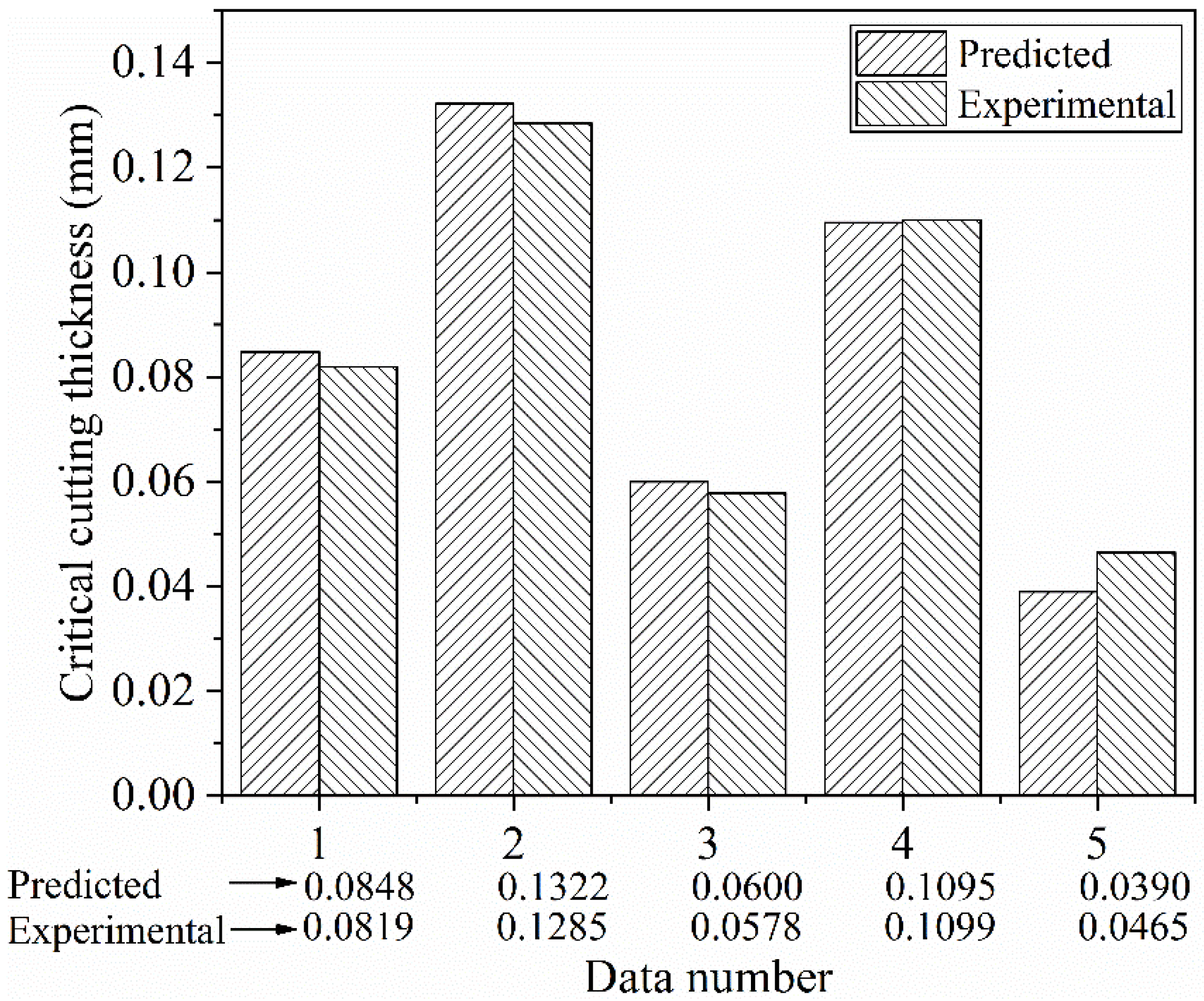
4.1. Prediction of Critical Cutting Thickness

Based on the established CSC bifurcation set equation, the predicted critical cutting thicknesses ac01 and ac02 of CSC are listed in Table 5. The straight double-edged tool with a combination of different cutting edge angles θ and rake angles γ0 (Table 5) was exploited to symmetrically and transversely feed the AISI 1045 steel disc workpieces in the prediction process. The following details need to be clarified:
In the prediction, three values of the cutting edge angle θ and the rake angle γ0 were taken, following regular change variations. To investigate the extrapolation prediction ability of the established bifurcation set equation, the three values of the cutting angle θ were taken at 35°, 50°, and 65°, and the three levels of the rake angle γ0 were taken at −20°, −10°, and 0°.
The established bifurcation set equation is a sixth-order algebraic equation of the control variables θ, γ0, and ac. When θ and γ0 are known, it is converted to a sixth-order algebraic equation of ac. Theoretically, there are at most six roots, that is, up to six critical cutting thicknesses ac0 can be predicted. However, the MATLAB program, used to solve the sixth-order algebraic equation mentioned above, can figure out two non-repeated positive real roots (ac01, ac02) of ac at most.

4.2. Design for the Experimental Verification of the Bifurcation Set Equation

A group of verification experiments was designed to verify the effectiveness of the established bifurcation set equation model and the accuracy of the critical conditions (such as the critical cutting thickness) predicted by the CSC model. For this group of experiments, the operational process and the measurement method for the critical cutting thickness were the same as those of the experiments for acquiring the CSC data under critical conditions. However, there was a difference in the setting of tool parameters in the verification experiments, including the edge angle θ, rake angle γ0, workpiece thickness b, feed amount f, and actual cutting thickness ac0 corresponding to the feed amount f, as shown in Table 5.

4.3. Verification Experiments Results and Discussions

According to the experimental design, six experiments were conducted to measure the actual critical cutting thickness ace by symmetrically and transversely feeding AISI 1045 steel disc workpieces with self-made high-speed steel straight double-edged tools. The column of a′ce in Table 5 lists the obtained experimental critical cutting thickness value. The following details should be clarified:
(1) During the cutting by tool number 4 in Table 5, the workpiece was severely deformed, and the experiment could not be completed as expected. In this case, the critical cutting thickness cannot be measured, and the prediction error of this tool for the critical cutting thickness cannot be calculated. So, the corresponding data were indicated by slash “/”. The reason for this result was that, for this tool, the two critical cutting thicknesses predicted by the bifurcation set equation were both large, i.e., ac01 = 0.1817 mm and ac02 = 0.2122 mm. The actual cutting thickness used for this experiment was larger than 0.2122 mm, which resulted in a very large cutting force. Additionally, the diameter of the workpiece was 180 mm, while the workpiece thickness calculated by the tool’s cutting edge angle was only 2.5 mm. In this case, the rigidity was obviously insufficient.
(2) As can be seen from Table 5, almost all the predicted values ac02 of the critical cutting thickness were greater than the actual experimental results. A possible reason for this phenomenon is: catastrophe theory asserts that the occurrence of catastrophe is determined by both the final values of the control variables and the change paths to these final values. In the verification experiments of the critical conditions of CSC, the cutting thickness changes monotonously from small to large (the change occurs when the tool cuts into the workpiece). So, only the sudden change in the smaller critical cutting thickness can be observed [30]. The machine tool used in the experiment cannot realize the variable feed cutting, which means that the cutting thickness cannot be changed from large to small. Therefore, it is theoretically impossible to trigger a catastrophe corresponding to the more immense predicted value of the critical cutting thickness ac02.
Table 5 also shows the relative error δ between the predicted value and the experimental results of the CSC bifurcation set equation. The error ranges from −16.13% to 3.81%, and the average error is −1.25%, while the average absolute error is 5.34%. In similar modeling studies using catastrophe theory, such as the chip angle catastrophe model [32] and the tool wear state catastrophe model [33], their prediction errors are both about 10%. Therefore, as a reference, we believe that the forecast result with an average absolute error of only 5.34% is a relatively good result. As shown in Figure 9, the predicted values are in good agreement with the experimental results.
The developed model can accurately predict the process conditions for CSC (including the tool geometry parameters and cutting parameters), and the generation of CSC can greatly reduce the cutting force, specific cutting force, and cutting power. That is to say, the research results actually provide a method to predict the tool geometry parameters and cutting parameters (or their combinations) that make the cutting process at a lower cutting force, specific cutting force, and cutting power. The application of this research result is that, by using the tool geometry parameters and cutting parameters predicted by the model for CSC, the cutting process can be performed at low cutting forces, low specific cutting forces, and low cutting powers.
Further, the general method to reduce the cutting force (power) in actual production is to increase the rake angle of the tool. However, an increase in the rake angle leads to a weakening of the strength and stiffness of the tool itself and a reduction in the load-bearing capacity. In addition, some tools are not suitable with large rake angle. For example, ceramic tools are generally processed with negative rake angles. As another example, Gouveia [41] analyzed the chips formed by two different types of end mills. He pointed out that the HPMT 3Z AlCrN end mill has a large negative rake angle of the tool (not so sharp), which consequently leads to higher friction loads between the cutting edges and chips. Meanwhile, the generated chips display greater surface irregularities. Our research found that, when cutting with a negative rake angle tool, as long as the tool geometry parameters and related process parameters are properly selected, the chips will be easily bifurcated, and the cutting force (power) can be greatly reduced. This research result actually provides a new feasible direction for the energy-saving optimization design of negative rake angle ceramic tools.
Based on current research, it is possible to predict the occurrence of CSC, but the chip morphology before and after CSC has not been deeply studied. The fractal theory [42] provides strong support for research in this direction. A comprehensive study of chip morphology before and after CSC will be the focus of future research.

5. Conclusions

Aiming at filling the research gap of the modeling of CSC and based on catastrophe theory, this paper proposes an experimental modeling method for the bifurcation set equation for CSC of a double-edged tool in symmetrical cutting. Using this method, according to the obtained experimental data of the critical conditions of CSC, a model that can predict the critical conditions is established. The validity and accuracy of the model are verified by experiments. The conclusions for this paper are summarized as follows:
(1) A method based on the principle of dichotomy and the captured chip flow video was proposed to obtain the critical conditions of CSC, and 22 sets of experimental data of the critical conditions were obtained through systematic cutting experiments.
(2) By analyzing the experimental data, it was found that, with the same tool, both the specific main cutting force and the specific feed force with CSC were much lower than those without CSC, and the maximum reduction under the experimental conditions reached 64.68%. It was also found that the larger the cutting edge angle and the absolute value of the negative rake angle are, the more likely it is that CSC is to be observed within a certain range of the process parameters.
(3) An experimental modeling method of the CSC bifurcation set equation has been proposed based on the standard mathematical model of the swallowtail catastrophe and the experimental data of the critical conditions. This method simplified the modeling process into a process of finding the optimal solutions to the coefficients of the mapping functions from the actual control variables (cutting edge angle θ, rake angle γ0, and cutting thickness ac) to the theoretical control variables (u, v, w).
(4) Following the above method, the coefficients of the mapping functions were solved based on the experimental data of the critical conditions of CSC when the straight double-edged tool was symmetrically traversing the AISI 1045 steel disc workpieces. The corresponding bifurcation set equation of CSC was established.
(5) Analyzing the bifurcation set surface can not only explain the cause of CSC (the equilibrium state of the system changes), but it can also predict and control CSC by adjusting the values of the actual control parameters.
(6) A set of validation experiments were completed. The results show that the predicted value of the critical cutting thickness for CSC is in good agreement with the experimental value. Therefore, the established CSC bifurcation set equation is correct and accurate.
This study laid a foundation for controlling and utilizing CSC. Additionally, it provides a new approach for the energy-saving optimization design of tool geometry and cutting process parameters.

Author Contributions

Conceptualization, Q.Y. and B.Z.; Data curation, M.X. and K.Y.; Formal analysis, Q.Y.; Funding acquisition, L.X.; Investigation, Q.Y., M.X. and K.Y.; Methodology, Q.Y., B.Z., L.X. and K.Y.; Project administration, L.X.; Validation, Q.Y.; Visualization, B.Z.; Writing—original draft, Q.Y.; Writing—review & editing, Q.Y. and L.X. All authors have read and agreed to the published version of the manuscript.

Funding

This research was funded by the National Natural Science Foundation of China, grant number 51675203.

Institutional Review Board Statement

Not applicable.

Informed Consent Statement

Not applicable.

Data Availability Statement

Not applicable.

Acknowledgments

All the experiments have been completed in the State Key Laboratory of Digital Manufacturing Equipment and Technology. All of the authors would like to express their sincere gratitude for the support provided during this research. We really appreciate Joseph T. Chan from California State University for his great efforts in proofreading the manuscript. In addition, we are also grateful to Rong Youmin from Huazhong University of Science and Technology for his valuable suggestions for improving this manuscript.

Conflicts of Interest

The authors declare no conflict of interest.

References

  1. Shi, H. Metal Cutting Theory: New Perspectives and New Approaches; Springer International Publishing: Cham, Switzerland, 2018; pp. 110–146. ISBN 978-3-319-73560-3. [Google Scholar]
  2. Wang, G.-C.; Fuh, K.-H.; Yan, B.-H. A new mathematical model for multifacet drills derived by using angle-solid model. Int. J. Mach. Tools Manuf. 2001, 41, 103–132. [Google Scholar] [CrossRef]
  3. Liu, G.; Wang, Y.; Zhang, H.; Gao, K.; Ke, Y.; Duan, Z. Research on helical milling specialized tool based on chip-splitting principle. J. Mech. Eng. 2014, 50, 176–184. [Google Scholar] [CrossRef]
  4. Zhou, L.; Dong, H.; Ke, Y.; Chen, G. Analysis of the chip-splitting performance of a dedicated cutting tool in dry orbital drilling process. Int. J. Adv. Manuf. Technol. 2016, 90, 1809–1823. [Google Scholar] [CrossRef]
  5. Stephenson, D.A.; Agapiou, J.S. Metal Cutting Theory and Practice, 3rd ed.; Taylor & Francis: London, UK; CRC Press: Boca Raton, FL, USA, 2016; pp. 44–46. ISBN 978-1-4665-8754-0. [Google Scholar]
  6. Zhou, W.; Li, S.; Liu, R.; Chu, X. Experimental and simulation investigation of multi-tooth cutting process of long fiber using copper wire continuous feeding. J. Mater. Process. Technol. 2019, 273, 116252. [Google Scholar] [CrossRef]
  7. Shi, H.-M.; Wang, J.-L. A model for non-free-cutting. Int. J. Mach. Tools Manuf. 1995, 35, 1507–1522. [Google Scholar] [CrossRef]
  8. Gao, H.; Zhang, Y.; Wu, Q.; Li, B. Investigation on influences of initial residual stress on thin-walled part machining deformation based on a semi-analytical model. J. Mater. Process. Technol. 2018, 262, 437–448. [Google Scholar] [CrossRef]
  9. Zhang, Y.; Guo, S.; Zhang, Z.; Huang, H.; Li, W.; Zhang, G.; Huang, Y. Simulation and experimental investigations of complex thermal deformation behavior of wire electrical discharge machining of the thin-walled component of Inconel 718. J. Mater. Process. Technol. 2019, 270, 306–322. [Google Scholar] [CrossRef]
  10. Khoshdarregi, M.R.; Altintas, Y. Dynamics of Multipoint Thread Turning—Part I: General Formulation. J. Manuf. Sci. Eng. 2018, 140, 061003. [Google Scholar] [CrossRef]
  11. Monkova, K.; Monka, P.P.; Sekerakova, A.; Hruzik, L.; Burecek, A.; Urban, M. Comparative Study of Chip Formation in Orthogonal and Oblique Slow-Rate Machining of EN 16MnCr5 Steel. Metals 2019, 9, 698. [Google Scholar] [CrossRef] [Green Version]
  12. Polvorosa, R.; Suárez, A.; de Lacalle, L.N.L.; Cerrillo, I.; Wretland, A.; Veiga, F. Tool wear on nickel alloys with different coolant pressures: Comparison of Alloy 718 and Waspaloy. J. Manuf. Process. 2017, 26, 44–56. [Google Scholar] [CrossRef]
  13. Jerold, B.D.; Kumar, M.P. Experimental investigation of turning AISI 1045 steel using cryogenic carbon dioxide as the cutting fluid. J. Manuf. Process. 2011, 13, 113–119. [Google Scholar] [CrossRef]
  14. Patwari, M.A.U.; Amin, A.K.M.N.; Faris, W. Identification of Instabilities of the Chip Formation and It’s Prediction Model During End Milling of Medium Carbon Steel (S45C). Am. J. Eng. Appl. Sci. 2010, 3, 193–200. [Google Scholar] [CrossRef] [Green Version]
  15. Shyha, I.; Gariani, S.; El-Sayed, M.A.; Huo, D. Analysis of Microstructure and Chip Formation When Machining Ti-6Al-4V. Metals 2018, 8, 185. [Google Scholar] [CrossRef] [Green Version]
  16. Urbikain, G.; Perez, J.M.; de Lacalle, L.N.L.; Andueza, A. Combination of friction drilling and form tapping processes on dissimilar materials for making nutless joints. Proc. Inst. Mech. Eng. B J. Eng. Manuf. 2018, 232, 1007–1020. [Google Scholar] [CrossRef]
  17. Tiffe, M.; Saelzer, J.; Zabel, A. Analysis of mechanisms for chip formation simulation of hardened steel. Procedia CIRP 2019, 82, 71–76. [Google Scholar] [CrossRef]
  18. Luk, W. The mechanics of symmetrical vee form tool cutting. Int. J. Mach. Tool Des. Res. 1969, 9, 17–38. [Google Scholar] [CrossRef]
  19. Yamamoto, A.; Nakamura, S. On the Chip Parting at V-shaped Groove Cutting. J. Jpn. Soc. Precis. Eng. 1978, 44, 1367–1372. [Google Scholar] [CrossRef]
  20. Shi, H. Chip-ejection interference in cutting processes of modern cutting tools. Sci. China Technol. Sci. 1999, 42, 275–281. [Google Scholar] [CrossRef]
  21. Xu, M.-X.; Xiong, L.-S.; Zhu, B.-Y.; Zheng, L.-F.; Yin, K. Experimental research on the critical conditions and critical equation of chip splitting when turning a C45E4 disc workpiece symmetrically with a high-speed steel double-edged turning tool. Adv. Manuf. 2022, 10, 1–16. [Google Scholar] [CrossRef]
  22. Rezayi Khoshdarregi, M.; Altintas, Y. Generalized modeling of chip geometry and cutting forces in multi-point thread turning. Int. J. Mach. Tools Manuf. 2015, 98, 21–32. [Google Scholar] [CrossRef]
  23. Zhu, B.; Xiong, L.; Xu, M. Double-edged cutting simulation with a new combined constitutive model for AISI 1045 steel. J. Mater. Process. Technol. 2022, 302, 117496. [Google Scholar] [CrossRef]
  24. Weng, J.; Zhuang, K.; Hu, C.; Zhu, D.; Guo, S.; Ding, H. A novel approach to thermal modeling based on three-dimensional analysis in turning Inconel 718 with round insert. J. Mater. Process. Technol. 2018, 266, 588–598. [Google Scholar] [CrossRef]
  25. Castrigiano, D.P.L.; Hayes, S.A. Catastrophe Theory, 2nd ed.; CRC Press: New York, NY, USA, 2018; pp. 1–9. ISBN 978-0-8133-4125-5. [Google Scholar]
  26. Poston, T.; Stewart, I.; Plaut, R.H. Catastrophe Theory and Its Applications; Pitman: London, UK, 1978; pp. 1–7. ISBN 0-273-01029-8. [Google Scholar]
  27. Woodcock, A.E.R.; Davis, M. Catastrophe Theory; Penguin: London, UK, 1978; pp. 76–92. ISBN 0-525-07812-6. [Google Scholar]
  28. Klamecki, B.E. Catastrophe Theory Models of Chip Formation. J. Eng. Ind. 1982, 104, 369–374. [Google Scholar] [CrossRef]
  29. Bao, J.; Liu, J.; Yin, Y.; Liu, T. Characterization and experiments on the friction catastrophe behaviors of brake material during emergency braking. Eng. Fail. Anal. 2015, 55, 55–62. [Google Scholar] [CrossRef]
  30. Cui, H.; Wan, X.; Xiong, L. Modeling of the catastrophe of chip flow angle in the turning with double-edged tool with arbitrary rake angle based on catastrophe theory. Int. J. Adv. Manuf. Technol. 2019, 104, 2705–2714. [Google Scholar] [CrossRef]
  31. Zhang, S.-N.; Cheng, D.-D.; Xiong, L.-S. Regularization of mathematical model for chip flow angle catastrophe. Adv. Manuf. 2021, 9, 568–579. [Google Scholar] [CrossRef]
  32. Zhu, B.; Xiao, Y.M.H.; Wan, X.; Xiong, L. Theoretical modeling and experimental verification of chip flow angle catastrophe in double-edged cutting considering non-linear effects. Int. J. Mech. Sci. 2019, 172, 105394. [Google Scholar] [CrossRef]
  33. Luo, Z. Study on catastrophe theory-based modeling and prediction of tool life. China J. Mech. Eng. 1994, 30, 103–112. [Google Scholar]
  34. Buchkremer, S.; Klocke, F.; Veselovac, D. 3D FEM simulation of chip breakage in metal cutting. Int. J. Adv. Manuf. Technol. 2015, 82, 645–661. [Google Scholar] [CrossRef]
  35. Zhang, D.; Zhang, X.-M.; Nie, G.-C.; Yang, Z.-Y.; Ding, H. In situ imaging based thermo-mechanical analysis of built-up edge in cutting process. J. Manuf. Process. 2021, 71, 450–460. [Google Scholar] [CrossRef]
  36. Arnold, V.I. Catastrophe Theory, 3rd ed.; Springer: Berlin/Heidelberg, Germany; New York, NY, USA, 1992; pp. 77–88. ISBN 978-3-540-548811-9. [Google Scholar]
  37. Gilmore, R. Catastrophe Theory for Scientists and Engineers; Dover Publications, Inc.: New York, NY, USA, 1984; pp. 34–47. ISBN 0-486-67539-4. [Google Scholar]
  38. Sun, J.; Tan, Q.-M. Research on catastrophe model of logistics capacity for logistics system of national economy mobilization. In Proceedings of the 2011 IEEE International Conference on Grey System & Intelliqent Service, Nanjing, China, 15–18 September 2011; pp. 855–860. [Google Scholar] [CrossRef]
  39. Li, H.; Feng, W.; Zhuang, W.; Hua, L. Microstructure Analysis and Segmented Constitutive Model for Ni-Cr-Co-Based Superalloy during Hot Deformation. Metals 2022, 12, 357. [Google Scholar] [CrossRef]
  40. Piyaratne, M.K.D.K.; Zhao, H.; Meng, Q. APHIDSim: A population dynamics model for wheat aphids based on swallowtail catastrophe theory. Ecol. Model. 2013, 253, 9–16. [Google Scholar] [CrossRef]
  41. Gouveia, R.M.; Silva, F.J.G.; Reis, P.; Baptista, A.P.M. Machining Duplex Stainless Steel: Comparative Study Regarding End Mill Coated Tools. Coatings 2016, 6, 51. [Google Scholar] [CrossRef] [Green Version]
  42. Mwema, F.M.; Akinlabi, E.T.; Oladijo, O.P.; Fatoba, O.S.; Akinlabi, S.A.; Tălu, S. Advances in Manufacturing Analysis: Fractal Theory in Modern Manufacturing. In Modern Manufacturing Processes, 1st ed.; Kumar, K., Davim, J., Eds.; Woodhead Publishing: Cambridge, UK, 2020; Chapter 2; pp. 13–39. ISBN 978-0-12-822774-9. [Google Scholar]
Figure 1. (a) Symmetrically transverse cutting AISI 1045 steel disc workpiece with the HSS straight double-edged tool; (b) The tool geometry parameters.
Metals 12 00878 g001
Figure 2. Schematic diagram of the experimental devices and cutting force measurement system.
Metals 12 00878 g002
Figure 3. Twenty-five cutting tools in the first round of the experiment.
Metals 12 00878 g003
Figure 4. Chip flow in the cutting experiment. (a) A single chip without CSC; (b) Chip-splitting Catastrophe observed in the experiments: Cutting edge angle θ = 45°, Rake angle γ0 = −10°, Critical cutting thickness ace = 0.0495 mm.
Metals 12 00878 g004
Figure 5. The chip morphology after chip-splitting catastrophe: Cutting edge angle θ = 45°, Rake angle γ0 = −10°, Critical cutting thickness ace = 0.0495 mm.
Metals 12 00878 g005
Figure 6. Flow diagram for solving the coefficients P.
Metals 12 00878 g006
Figure 7. Three dimensional diagram of the swallowtail catastrophe bifurcation set of CSC.
Metals 12 00878 g007
Figure 8. The position of the critical point (Point 2) on the bifurcation set surface.
Metals 12 00878 g008
Figure 9. Comparison of the predicted critical cutting thickness with the experimental data.
Metals 12 00878 g009
Table 1. Chemical composition of the steel AISI 1045 in weight (%).
CSiMnPSMgCrNiMo
0.4500.1760.6020.0180.027<0.00050.0650.0260.003
CuAlTiVCoAsSnNFe
0.0960.0160.00050.00110.00390.00290.0060.002>98.5
Table 2. The process parameters corresponding to different cutting edge angles.
Cutting Edge Angle
θ/(°)
Actual
Cutting Thickness
ace0/mm
Feed
f/(mm/r)
Workpiece Thickness
b/mm
Cutting Edge
Angle
θ/(°)
Actual
Cutting
Thickness
ace0/mm
Feed
f/(mm/r)
Workpiece Thickness
b/mm
400.04980.0654.60450.04950.0704.25
0.09960.1300.09900.140
0.15320.2000.14140.200
0.19920.2600.19800.280
500.05460.0853.86550.04870.0853.00
0.09640.1500.09750.170
0.14460.2250.14910.260
0.19280.3000.19500.340
600.05000.1003.00600.15000.3003.00
0.10000.2000.20000.400
Table 3. Cutting force and chip-splitting states corresponding to the critical conditions and their boundary values.
Data
Number
No.
Rake
Angle
γ0/(°)
Cutting
Edge
Angle
θ/(°)
Critical
Cutting Thickness
ace/mm
Specific
Main
Cutting
Force
Fc/(N/mm2)
Specific
Feed
Force
Ff/(N/mm2)
Y/NData
Number
No.
Rake
Angle
γ0/(°)
Cutting
Edge
Angle
θ/(°)
Critical
Cutting Thickness
ace/mm
Specific
Main
Cutting
Force
Fc/(N/mm2)
Specific
Feed
Force
Ff/(N/mm2)
Y/N
1−15400.04983635 2544 Y12−5550.05163298 1712 Y
−13400.04983537 2155 Y−4550.05163349 1473 Y
−10400.04983477 3126 N0550.05165039 2190 N
2−15400.04983635 2544 Y13-10550.05163388 1744 Y
−15400.07663218 2252 Y−10550.08032592 1727 Y
−15400.09964404 2619 N−10550.09755176 3844 N
3−10400.04983477 3025 N14−15550.09753133 1692 Y
−10430.05123395 2021 Y−12550.09753056 1574 Y
−10450.05123382 1810 Y−10550.09755176 3844 N
4−20450.09901928 1367 Y15−20550.14595351 4216 Y
−18450.09903145 1524 Y−18550.14595516 4772 Y
−15450.09904798 3259 N−15550.14595206 3860 N
5−15450.04953673 3441 Y16−10550.09755176 3844 N
−15450.07073614 2181 Y−10580.10072898 2349 Y
−15450.09904798 3259 N−10600.10072915 1703 Y
6−10450.04953498 1872 Y17−15550.14915094 3777 N
−8450.04953441 2057 Y−15580.14842782 2325 Y
−5450.04954923 2532 N−15600.14842782 2260 Y
7−10500.04823658 2099 Y18−5600.05003470 2923 Y
−6500.04823510 1317 Y−5600.07503078 1816 Y
−5500.04825425 1829 N−5600.10005083 5140 N
8−10500.04823658 2099 Y19−10600.10002935 1715 Y
−10500.07073484 2494 Y−8600.10002915 2555 Y
−10500.10104625 3592 N−5600.10005083 5140 N
9−15500.10102893 1792 Y20−10600.10002935 1715 Y
−13500.10102965 1789 Y−10600.12002785 1532 Y
−10500.10103437 3592 N−10600.15004932 4109 N
10−15500.10102893 1792 Y21−15600.15002752 2236 Y
−15500.12212864 1906 Y−13600.15002696 1861 Y
−15500.14464832 4157 N−10600.15004932 4109 N
11−5500.05464789 1615 N22−15600.15002752 2236 Y
−5530.05123324 2116 Y−15600.17002656 1830 Y
−5550.05123324 1725Y−15600.200051243078N
Table 4. Optimized parameters P.
ParameterFinal ValueParameterFinal Value
p1−0.31745p7−0.00034
p20.00647p8−0.05225
p3−0.01364p90.00955
p4−1.84204p10−0.00020
p5−0.01249p110.00038
p60.00027p120.04931
Table 5. Prediction results and the verification experimental parameters and results of critical cutting thickness.
Tool
Number
Cutting Edge Angle
θ/(°)
Rake Angle
γ0/(°)
Predicted
Critical Cutting Thickness
ac01/mm)
Predicted
Critical Cutting Thickness
ac02/mm
Feed
f/(mm/r)
Actual
Cutting Thickness
ac0/mm
Workpiece Thickness
b/mm
Experimental
Critical Cutting Thickness
a′ce/mm
Relative Error
δ/(%)
135−200.08480.09260.0500.04104.910.08193.54
0.1300.1065
250−200.13220.15590.1400.09003.860.12852.88
0.2800.1800
3−100.06000.08040.0500.03210.05783.81
0.1500.0964
465−200.18170.21220.3800.16062.54//
0.4500.1902
5−100.10950.13300.1300.05490.1099−0.36
0.2800.1183
600.03900.04860.0500.02110.0465−16.13
Note: (1) The maximum and minimum relative errors between the predicted value and the experimental value are underlined and bolded. (2) The slash”/” indicates that the critical cutting thickness is not obtained in the actual experiment, so the corresponding prediction error for the critical cutting thickness cannot be calculated.
Publisher’s Note: MDPI stays neutral with regard to jurisdictional claims in published maps and institutional affiliations.

