1. Introduction
One of the most important problems in rolling processes is the control of pressure on the strip. This phenomenon has great influence on the quality of the strip, and the control of this process requires extensive study of each variable, such as wear, crown control, and stress distribution.
Strip flatness and crown control are the basis of strip shape quality. There have been many studies focusing on this issue using mathematical models and the Finite Element Method (FEM). Yang et al. [
1] studied the backup roll (BUR) contour in smart crown tandem cold mills. Li et al. [
2] conducted the same study for a hot rolling mill. Wang et al. [
3] used a negative crown in work rolls (WR). Wang et al. and Cao et al. [
4,
5] carried out the same study for a hot rolling mill using a Continuous Variable Crown (CVC) in the backup rolls and the work rolls. Liu et al. [
6] complemented these studies by considering axial forces in the analysis; and all of them concluded that the contact pressure concentration that exists between work and backup rolls have direct influence on the shape and quality of the strip. The thermal crown is another factor that influences the control of flatness and occurs in cold rolling mills. However, it is more critical in hot rolling mills applications. Chang, Galantucci and Tricarico, Hacquin et al. and Zhao et al. [
7,
8,
9,
10] concluded that the thermal crown is generated with its maximum point in the center of the rolls, and it is more severe in work rolls due to direct contact with the strip, so an adequate cooling system must be used to avoid excessive wear. Li et al. [
11] states that the Bending Force compensates for the effects of the thermal crown and wear.
The wear on the work rolls is a topic widely studied by S. Spuzic and Strafford, Turk et al. and Li et al. [
12,
13,
14], and their studies specify that wear increases as the rolling campaign progresses. Rumualdo et al. [
15] states that wear becomes more critical in BUR because the rolling campaigns are longer than in the WR. Also, the WRs remain for several hours in each campaign, while the BURs have lamination campaigns of at least fourteen days.
Liu et al. [
16] conducted an analysis of rolling pressure along the strip width in cold rolling process, and Zhang et al. [
17] did the same analysis for a hot rolling strip; both studies concluded that the peak of maximum pressure concentration was generated at the end of the body in the backup rolls. Kong et al. and Cao et al. [
18,
19] complemented this study by analyzing different widths of the strip, and as a preventive measure to reduce the concentration of stress, they analyzed different types of chamfers at the ends of the body for the backup rolls.
Liu et al. [
6] analyzed the rolls using a double cantilever model with the fulcrum of the beams in a centerline mill for their study of four-high CVC, and Jiang et al. [
20] used the same mathematical model in order to theoretically analyze the cold rolling process using an ultra-thin strip with roll edge kiss.
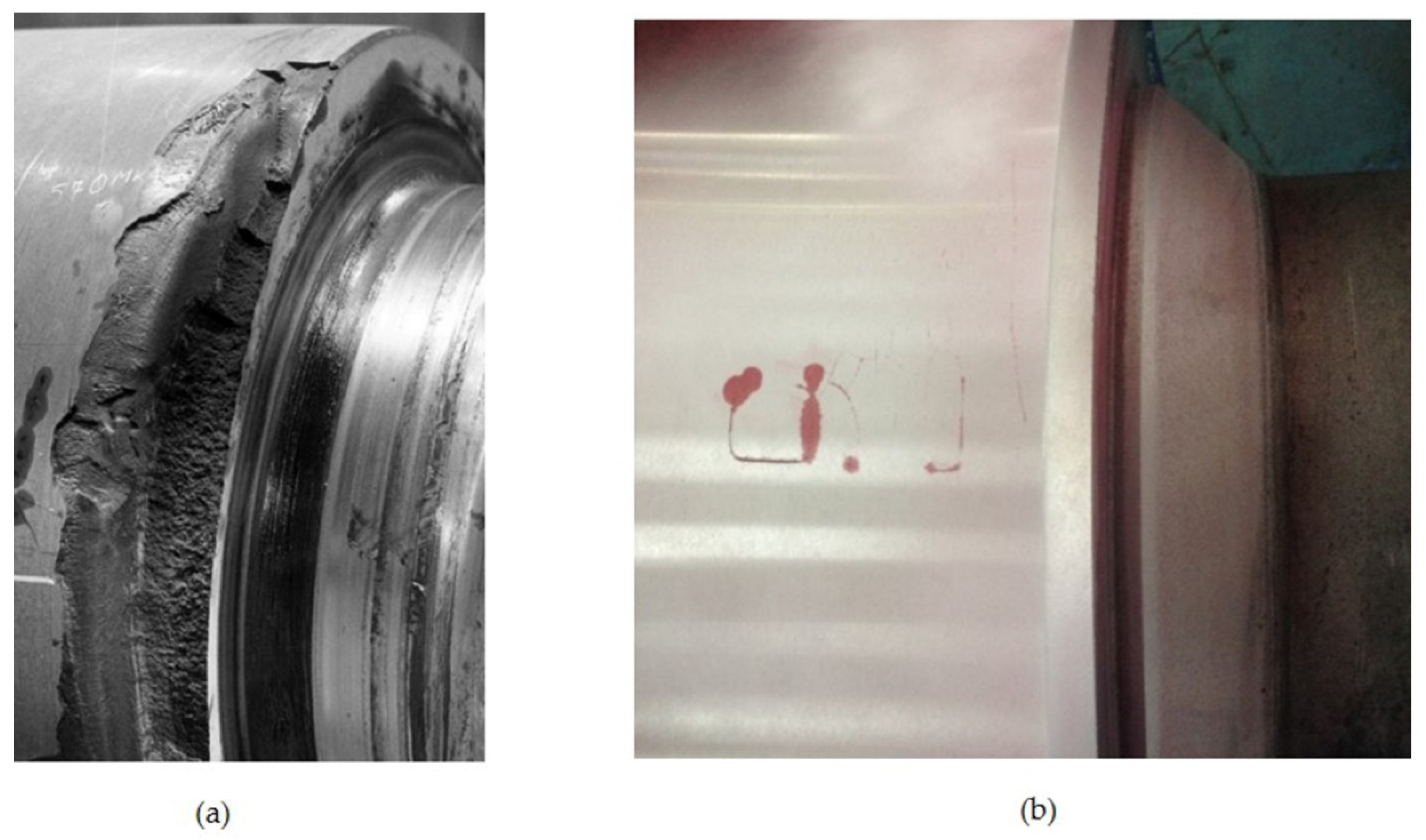
When the stress concentration is not controlled, excessive wear can be generated, which affects the pressure distribution, and in extreme cases, there are operational accidents with cracks and fractures of rolls at the ends of the work barrel as shown in the images of
Figure 1a for BUR and
Figure 1b for WR.
It is impossible to avoid elastic deformation of the rolls due to the rolling loads, and this could be critical, in combination with stress concentration and crown shape. There is always a latent risk of an operational accident, yet such risk can be reduced with a more complete understanding of the rolling process. Useful predictive data can be collected by FEM of rolls as a double cantilever model with the fulcrum of beams in a centerline mill.
According to previous studies, CVC is the best geometry for pressure distribution control in BURs [
4,
5]. However, this geometry requires grinding machines with controls and many mills do not have access to them. Thus, it is essential to carry out this study considering traditional positive, negative and flat-shaped crowns. In addition, the fact that the thermal crown resembles a positive crown, and the wear on the rolls of a negative crown must be taken into account.
2. Materials and Methods
The deformation of the rolls is directly related to the dimensions of the rolls, the support points and the application of rolling loads, as shown in the schematic of
Figure 2.
The forces causing the work roll deformation include rolling force, inter-roll force, and work roll bending force. Work roll deflection at element
i is described by Jiang et al. and Wang [
20,
21] and can be expressed as:
where
yW (
i) is the vertical deformation of the work roll at element
i,
gW (
i,
j) is the work roll deflection influence function due to the combined bending and shear forces generated by rolling and inter-roll force at element
j;
pi is the rolling force at element
i.
qj is the contact force between work roll and backup roll at element
j.
FW is the work roll bending force,
gFW (
i) is the work roll bending influence function due to the work roll bending force.
The backup roll deflection is caused only by the inter-roll force, so backup roll deflection at element
i can be expressed as [
20,
21]:
where
yB (
i) is the vertical deformation of the backup roll at element
i,
gB (
i,
j) is the backup roll deflection influence function due to the combined bending and shear forces generated by inter-roll force at element
j.
The force causing flattening between the work roll and the strip is the rolling force, and the force causing the flattening between the work roll and backup roll is the inter-roll force. Therefore, the flattening at element
i can be expressed as [
20,
21]:
where
gWS (
i,
j) is the flattening influence function of work roll and strip due to the rolling force at element
j;
nL and
nR are the element numbers at the left and right edges of the strip according to the second numbering rule;
gWB (
i,
j) is the flattening influence function of the work roll and the backup roll due to the inter-roll force at element
j.
The analyses of the distribution of stress and the deformation of rolls for the rolling process are based on an FEM employing ANSYS Mechanical Static Structural, considering the main variables and conditions in the process of rolling and described by the parameters in
Table 1. The rolling and bending forces are uniformly distributed, and are applied in the bearing areas. The rolls and strip are considered to behave flexibly, with general joints in the lateral face, which only allow for vertical movement in the direction of force application and roll deformation. The mesh for all the simulations had 461,800 nodes and 240,076 elements, with two zones of hexahedral elements with 20 nodes and tetrahedral elements with 10 nodes. The contact region mesh is refined using 20 layers with a growth rate of 1.1. Moreover, there are two contact zones, one of them between BUR and WR and the other one between WR and Strip. To avoid slipping of components in the contact zones, a bonded system is implemented without penetration.
The data considered for the analysis are those established for stand M-5 of a hot rolling mill, in which the materials of the rolls are 5% Cr-forged steel for the backup roll and nodular iron Indefinite Chilled Double Pour (ICDP) for the work roll, rolling a structural steel.
According to previous studies by Wang et al. and Cao et al. [
4,
5], the best pressure distribution is obtained by CVC crown; therefore, it is considered the worst case, and analysis of such combinations are used for positive, negative and flat crowns. When considering a thermal crown, the heat generated in the roll expands the material forming a positive crown according to Chang, Galantucci and Tricarico, Hacquin et al. and Zhao et al. [
7,
8,
9,
10]. Thus, we considered a thermal crown of 0.100 mm for the backup rolls and 0.150 mm for the work rolls.
According to the calculations made by Liu et al. and Rumualdo et al. [
6,
15], it has been established that the greatest wear occurs in the center of the rolls based on the wear parameters. According to the periods of the rolling campaigns, these are much longer for the backup rolls, with at least fourteen days of continuous operation. The values considered critical are 0.200 mm and 0.525 mm for the work and backup rolls, respectively, and negative crowns with these values will be used to simulate wear. Finally, the use of flat geometries is applied to get an idea of the behavior when crowns are not used, or when the thermal crown compensates for the wear generated.
The analysis of the distribution of stress and deformation of rolls for the rolling process is based on a FEM considering all the possible combinations of crown shape (positive, negative, and flat), as shown in
Table 2.
Author Contributions
R.S. Conceived and designed the simulations, S.A.A. and I.C. performed the simulations and wrote the paper, A.P. and S.M.S.M. analyzed the data.
Funding
This research received no external funding.
Acknowledgments
This work was supported by the Universidad Autónoma de Coahuila.
Conflicts of Interest
The authors declare no conflict of interest.
References
- Guanghui, Y.; Jianguo, C.; Jie, Z.; Shenghui, J.; Renwei, T. Backup roll contour of a Smart Crown tandem cold rolling mil. J. Univ. Sci. Technol. Mater. 2008, 15, 357–361. [Google Scholar]
- Li, H.; Xu, J.; Wang, G.; Shi, L.; Xiao, Y. Development of Strip Flatness and Crown Control Model for Hot Strip Mills. J. Iron Steel Res. Int. 2010, 17, 21–27. [Google Scholar] [CrossRef]
- Wang, X.D.; Li, F.; Li, B.H.; Zhu, G.S.; Li, B.; Zhang, B.H. VCR back-up roll and negative work roll contour design for solving roll spalling and transfer bar profile problems in hot strip mil. Ironmak. Steelmak. 2010, 37, 633–640. [Google Scholar] [CrossRef]
- Wang, X.D.; Li, F.; Li, B.H.; Zhu, G.S.; Li, B. Design and Application of an Optimum Backup Roll Contour Configured with CVC Work Roll in Hot Strip Mill. ISIJ Int. 2012, 52, 1637–1643. [Google Scholar] [CrossRef]
- Cao, J.; Wei, G.; Zhang, J.; Chen, X.; Zhou, Y. VCR and ASR technology for profile and flatness control in hot strip mills. J. Cent. South. Univ. Technol. 2008, 15, 264–270. [Google Scholar] [CrossRef]
- Liu, G.; Li, Y.; Huang, Q.; Yang, X. Axial Force Analysis and Roll Contour Configuration of Four-High CVC Mill. Math. Probl. Eng. 2018, 2018. [Google Scholar] [CrossRef]
- Der-Form, C. Thermal stresses in work rolls during the rolling of metal strip. J. Mater. Process. Technol. 1999, 94, 45–51. [Google Scholar] [CrossRef]
- Galantucci, L.M.; Tricarico, L. Thermo-mechanical simulation of a rolling process with an FEM approach. J. Mater. Process. Technol. 1999, 92–93, 494–501. [Google Scholar] [CrossRef]
- Hacquin, A.; Montmitonnet, P.; Guillerauit, J.-P. A steady state thermo-elastoviscoplastic finite element model of rolling with coupled thermo-elastic roll deformation. J. Mater. Process. Technol. 1996, 60, 109–116. [Google Scholar] [CrossRef]
- Zhao, N.; Cao, J.; Zhang, J.; Su, Y.; Yan, T.; Rao, K. Work roll thermal contour prediction model of nonoriented electrical steel sheets in hot strip mills. J. Univ. Sci. Technol. Beijing Mater. 2008, 15, 352–356. [Google Scholar] [CrossRef]
- Li, Y.; Cao, J.; Yang, G.; Dun, W.; Zhou, Y.; Ma, H. ASR Bending Force Mathematical Model for the Same Width Strip Rolling Campaigns in Hot Rolling. Steel Res. Int. 2014, 86, 567–575. [Google Scholar] [CrossRef]
- Spuzic, S.; Strafford, K.N. Wear of hot rolling mill rolls: An overview. Wear 1994, 176, 261–271. [Google Scholar] [CrossRef]
- Turk, R.; Fajfar, P.; Robic, R.; Perus, I. Prediction of hot strip mill roll wear. Metalugija 2002, 41, 47–51. [Google Scholar]
- Li, C.S.; Liu, X.H.; Wang, G.D.; Yang, G. Experimental investigation on thermal wear of high speed steel rolls in hot strip Rolling. Mater. Sci. Technol. 2002, 18, 1581–1584. [Google Scholar] [CrossRef]
- Rumualdo Servin, A.; Garcia, R.M. Development of Mathematical Model for Control Wear in Backup Roll for Hot Strip Mill. J. Iron Steel Res. Int. 2014, 21, 46–51. [Google Scholar] [CrossRef]
- Liu, X.; Xu, S.; Li, S.; Xu, J.; Wang, G. FEM Analysis of Rolling Pressure Along Strip Width in Cold Rolling Process. J. Iron Steel Res. Int. 2007, 14, 22–26. [Google Scholar] [CrossRef]
- Zhang, G.; Xiao, H.; Wang, C. Three-Dimensional Model for Strip Hot Rolling. J. Iron Steel Res. Int. 2006, 13, 23–26. [Google Scholar] [CrossRef]
- Kong, N.; Cao, J.; Wang, Y.; Tieu, A.; Kiet, Y.; Hou, L.; Wang, Z. Development of Smart Contact Backup Rolls in Ultrawide Stainless Strip Rolling Process. Mater. Manuf. Process. 2014, 29, 129–133. [Google Scholar] [CrossRef]
- Cao, J.; Chai, X.; Li, Y.; Kong, N.; Jia, S.; Zeng, W. Integrated design of roll contours for strip edge drop and crown control in tandem cold rolling mills. J. Mater. Process. Technol. 2018, 252, 432–439. [Google Scholar] [CrossRef]
- Jiang, Z.Y.; Wei, D.; Tieu, A.K. Analysis of cold rolling of ultra thin strip. J. Mater. Process. Technol. 2009, 209, 4584–4589. [Google Scholar] [CrossRef]
- Wang, G.D. The Shape Control and Theory; Metallurgical Industry Press: Beijing, China, 1986; pp. 246–249. [Google Scholar]
Figure 1.
Roll failures produced for stress concentration: (a) Backup Roll spalling; (b) Work Roll cracks.
Figure 2.
Schematic of the main dimensional variables for four high rolling mill.
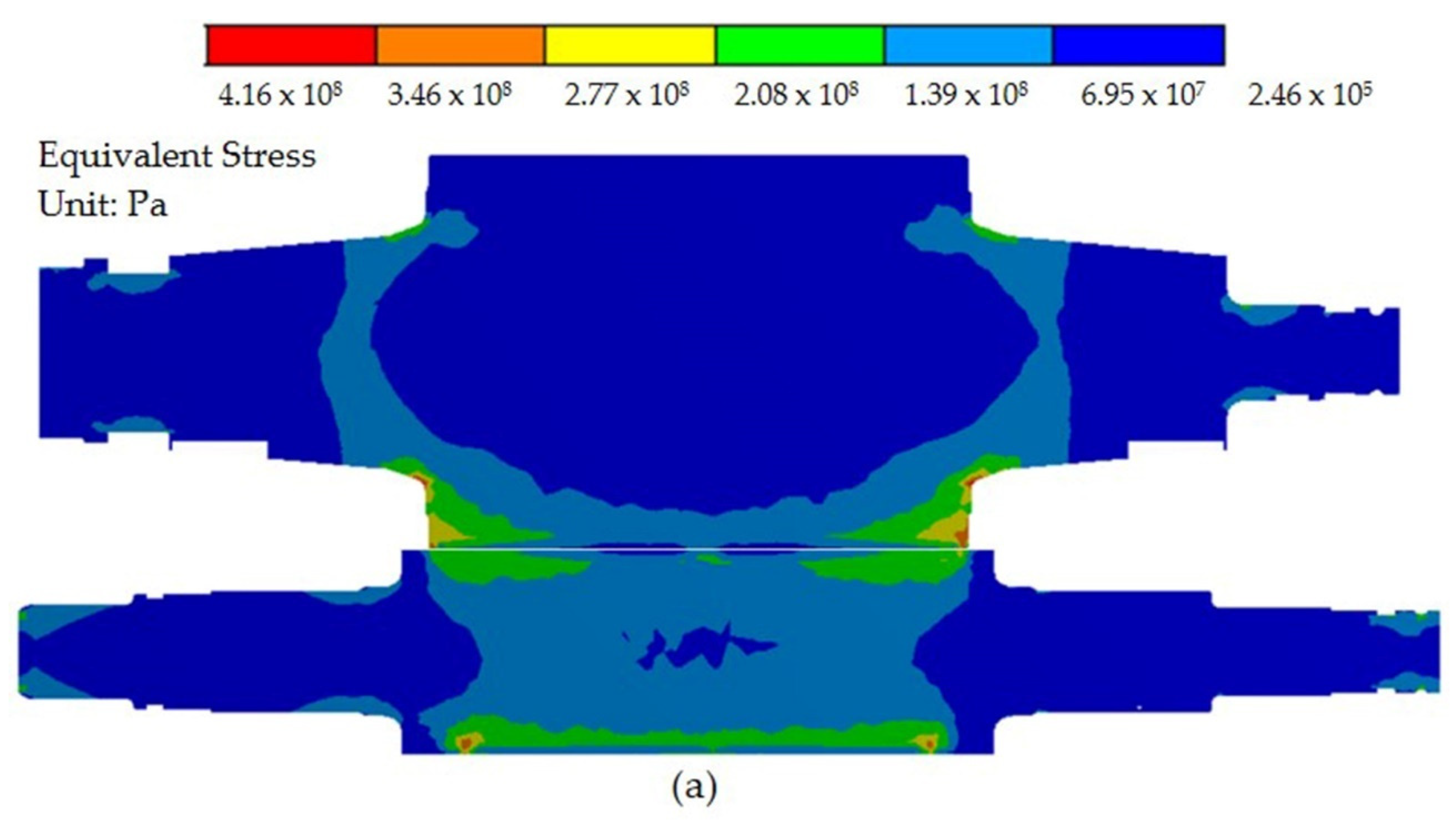
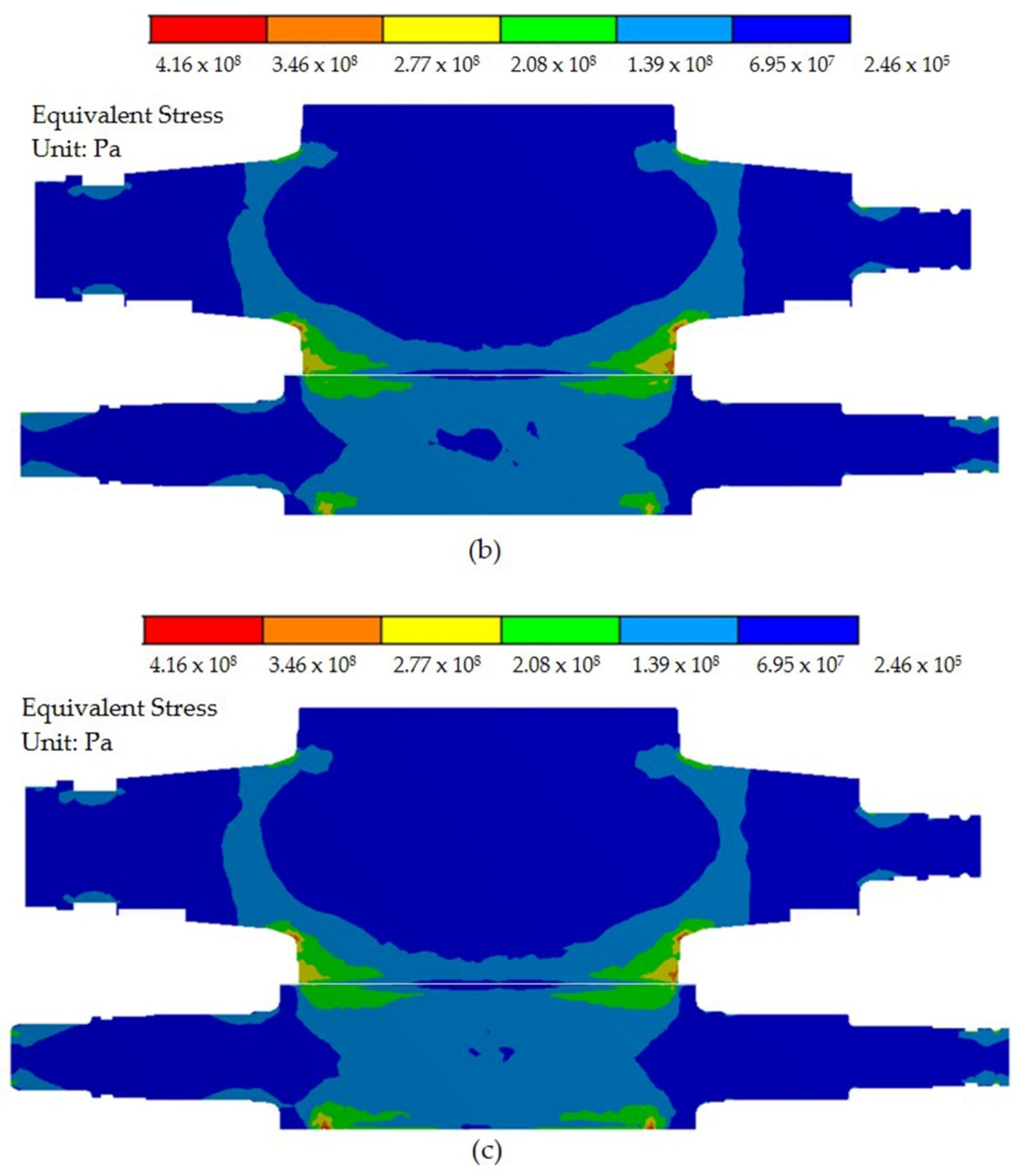
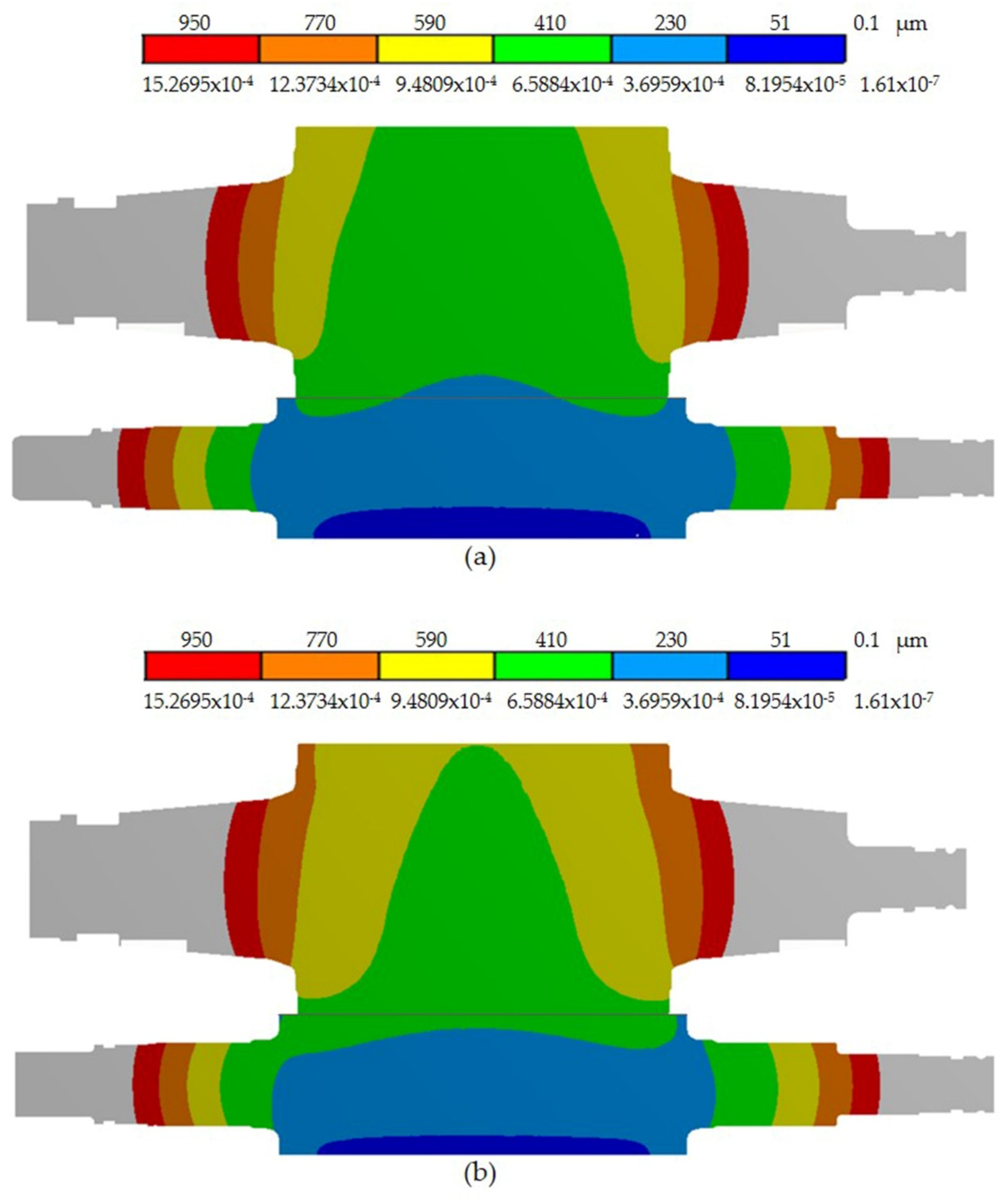
Figure 3.
Stress distribution for combinations of crowns: (a) combination 1, (b) combination 2, and (c) combination 3.
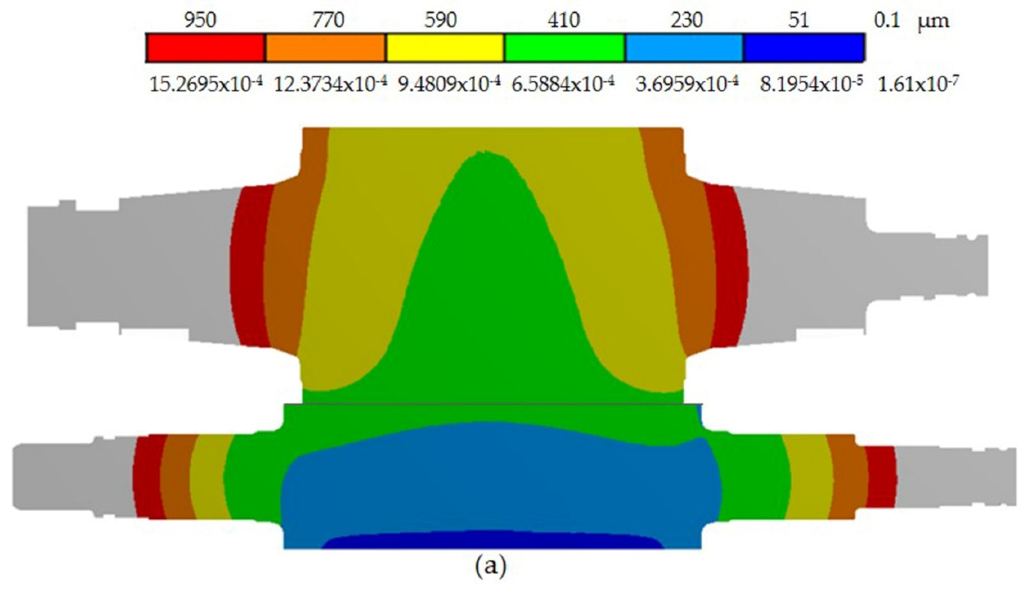
Figure 4.
Stress distribution for combinations of crown: (a) combination 4, (b) combination 5, and (c) combination 6.
Figure 5.
Stress distribution for combinations of crown: (a) combination 7, (b) combination 8 and (c) combination 9.
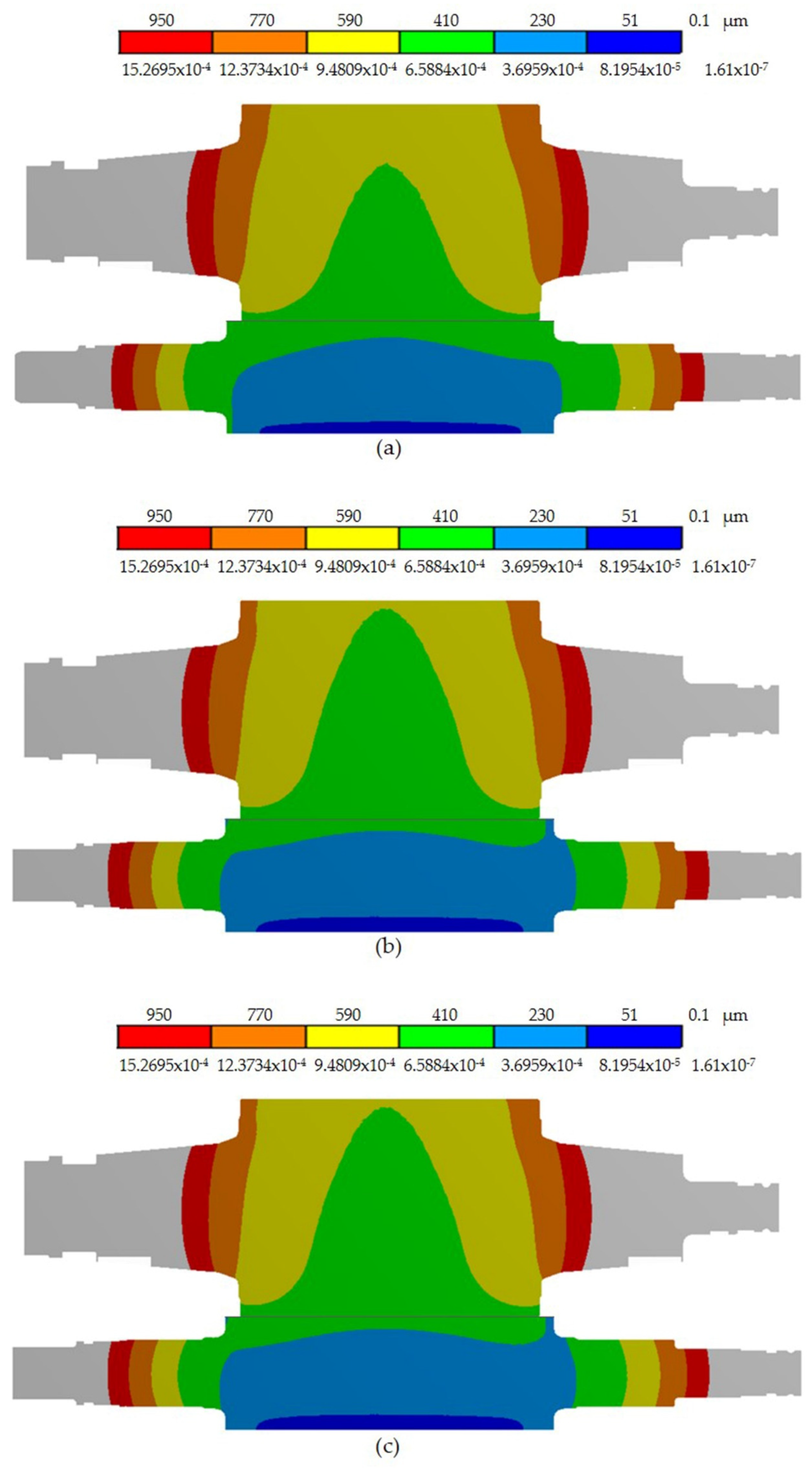
Figure 6.
Roll deflection distribution for combinations of crown: (a) combination 1, (b) combination 2, and (c) combination 3.
Figure 7.
Roll deflection distribution for combinations of crown: (a) combination 4, (b) combination 5, and (c) combination 6.
Figure 8.
Roll deflection distribution for combinations of crown: (a) combination 7, (b) combination 8, and (c) combination 9.
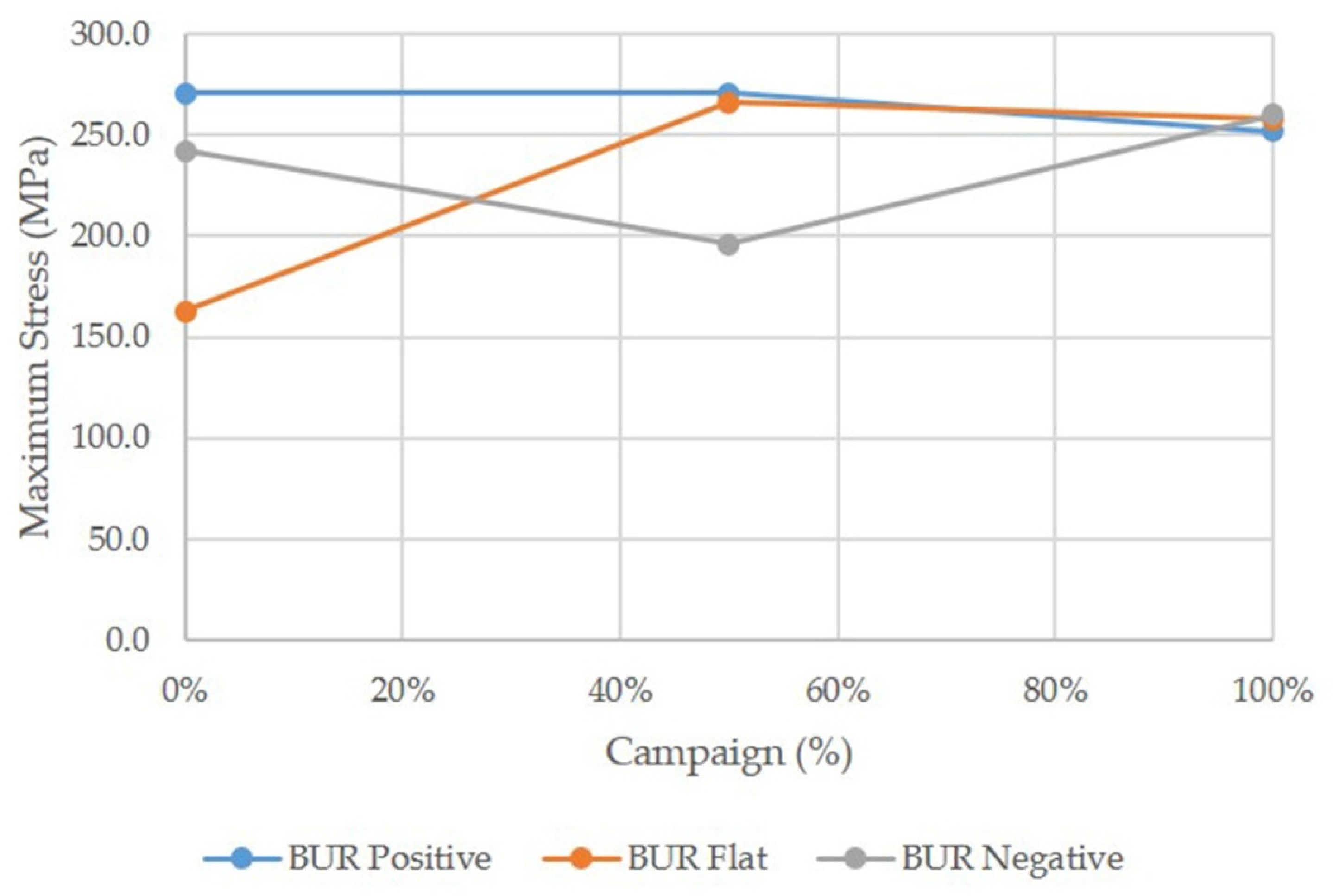
Figure 9.
Graph of the stress distribution curves for all mechanical contact combinations analyzed on BUR.
Figure 10.
Expected stress distribution behavior for different combinations of contact geometries during a rolling campaign of a BUR.
Figure 11.
Graph of deformation distribution curves for all mechanical contact combinations analyzed.
Table 1.
Parameter of the three dimensions finite element model of roll stacks.
| Model Parameter | Value |
|---|
| Work roll diameter Dw | 650.875 mm |
| Work roll barrel length Lw | 1897.20 mm |
| Work roll neck diameter Dnw | 384.175 mm |
| Work roll Bending force length LBf | 2747.20 mm |
| Backup roll diameter Db | 1244.60 mm |
| Backup roll barrel length Lb | 1727.20 mm |
| Backup roll neck diameter Dnb | 678.49 mm |
| Backup roll Rolling force length LRf | 2717.80 mm |
| Strip width W | 1574.8 mm |
| Strip thickness H | 2.5 mm |
| Rolling force Rf | 38,000 kN |
| Bending force Bf | 400 kN |
| Poisson’s ratio work roll | 0.3 |
| Poisson’s ratio backup roll | 0.3 |
| Young’s modulus work roll | 210 GPa |
| Young’s modulus backup roll | 220 GPa |
| Work Roll Crown | 0.1016 mm |
| Backup Roll Crown | 0.0762 mm |
| Young’s modulus strip | 210 MPa |
| Maximum Thermal crown WR | 0.150 mm |
| Maximum Thermal crown BUR | 0.100 mm |
| Maximum wear WR | 0.200 mm |
| Maximum wear BUR | 0.525 mm |
Table 2.
Combinations of crown shape analyzed.
| Combination | Configuration |
|---|
| 1 | BUR Positive–WR Positive |
| 2 | BUR Positive–WR Flat |
| 3 | BUR Positive–WR Negative |
| 4 | BUR Flat–WR Positive |
| 5 | BUR Flat–WR Flat |
| 6 | BUR Flat–WR Negative |
| 7 | BUR Negative–WR Positive |
| 8 | BUR Negative–WR Flat |
| 9 | BUR Negative–WR Negative |
© 2019 by the authors. Licensee MDPI, Basel, Switzerland. This article is an open access article distributed under the terms and conditions of the Creative Commons Attribution (CC BY) license (http://creativecommons.org/licenses/by/4.0/).


