Study of Inconel 718 Welded by Bead-On-Plate Laser Welding under High-Frequency Micro-Vibration Condition


1
School of Material Engineering, Shanghai University of Engineering Science, Shanghai 201620, China
2
Shanghai Collaborative Innovation Center of Laser Advanced Manufacturing Technology, Shanghai 201620, China
*
Author to whom correspondence should be addressed.
Metals 2019, 9(12), 1335; https://0-doi-org.brum.beds.ac.uk/10.3390/met9121335
Submission received: 26 November 2019
/
Revised: 8 December 2019
/
Accepted: 8 December 2019
/
Published: 11 December 2019
Abstract
:Inconel 718 alloy laser-welded joints have poor mechanical properties due to the presence of Laves phases and liquation cracks. This paper intends to solve the above problems by high-frequency micro-vibration-coupled bead-on-plate laser welding. According to the shape of the weld beam, the upper part of the weld is defined as the nail head, and the lower part is the nail body. The results showed that high-frequency micro-vibration can achieve grain refinement. The micro-vibration could break the primary dendrite arm to form secondary dendrite and reduce epitaxial growth of the cellular crystal region. Micro-vibration exacerbated the flow of Niobium (Nb) elements surrounded by dendrites and reduced dendritic segregation, which decreased the formation of Laves phases. The combination of interdendritic Nickel (Ni), Titanium (Ti), and Nb and the precipitation of strengthening phases γ′ and γ″ were promoted. When the vibration acceleration was 50.10 m/s2, it could inhibit the formation of Laves phases among dendrites and the size of the bulk Laves phase was effectively reduced. The cracks generated in the Inconel 718 alloy were distributed at three locations including the nail-head, the nail-body, and the junction of nail-head and nail-body. When the vibration frequency was 919 Hz, the length of the liquation crack reduced from 180 to 110 μm. While under 1331 Hz, the expansion of the liquation crack was extended, with the length of 200 μm.
1. Introduction
Inconel 718 nickel-based alloy has superior oxidation resistance, thermal stability, corrosion resistance, and high temperature strength (high temperature fatigue strength, high temperature tensile strength, creep resistance) in a high temperature environment from 650 to 1000 °C. It is widely used in aviation, aerospace, energy, chemical, communications, electronics, and automotive manufacturing [1,2,3].
In recent years, different welding methods and process parameters of Inconel 718 alloy have been studied. They found some problems in the process of welding Inconel 718 and explained the causes of these problems. Odabasi et al. [4] obtained the “wine-shaped” weld morphology by laser welding of Inconel 718 alloy. The microstructure of the Inconel 718 weld consisted of austenite dendrites and Laves phases. The grains near the fusion line appeared massive and columnar [5]. The dendrites were rich in Ni, Iron (Fe), and Chromium (Cr), while the Laves phase among the dendrites was rich in Nb, Molybdenum (Mo), Silicon (Si), and Ti [4]. Wang et al. [6] studied the segregation behavior of Nb during solidification of Inconel 718 by Scanning Electron Microscope (SEM) and Energy Dispersive Spectrometer (EDS). As the molten pool solidifies continuously, segregation of Nb in the liquid promotes the precipitation of high Nb precipitates during this process. The formation of these precipitates consume Nb in the surrounding area, which lead to a re-distribution of nearby alloying elements and liquid density. Lertora [7] and Tharappel et al. [8] considered that the Laves phase was the main cause of liquation cracks. The formation of Laves phases depends on the initial grain size and the composition of the matrix metal. The fine grains in the Heat Affected Zone (HAZ) can be the largest limitation to the tendency of microcracks to form. Ramkumar et al. [9] used laser welding of Inconel 718 and AISI 416, whereby the Laves phase caused low impact properties of the joint.
Vibration-assisted welding (VAW) has emerged as a successful replacement for heat treatments and post-weld vibration treatments of arc welds to improve its mechanical properties [10]. It is a cyclical external force (exciting force) applied to the workpiece to be welded during the conventional welding process, so that the weldment is forced to vibrate. Thus, the purpose of optimizing the comprehensive performance of the joint is achieved. The effect of vibration on a weld is embodied in the remarkable refinement of weld grain [11,12,13,14] and the reduction of welding hot cracking occurrence probability. Anbarasan et al. [15] used mechanical arc oscillating techniques to weld Inconel 718, which resulted in grain refinement and Nb segregation reduction at a frequency of 50 Hz. Wang et al. [16] studied vibration-assisted Gas Tungsten Arc Welding (GTAW) welding of Inconel 601H alloy and found that the grain refinement effect was produced at the weld during low-frequency vibration. The γ′ phase showed a dispersed distribution at the same time. They also believed that the vibration-caused generation of free crystals was the main mechanism of grain refinement. Thavamani et al. [17] used ultrasonic vibration-assisted GTAW to weld Inconel 718 alloy. The test found that the dendrite length decreased from 1256 to 89 μm, and the thermal crack sensitivity decreased from 47.5% to 13.3%. Therefore, they believed that dendritic fragmentation and grain size refinement were the main reason for reducing the tendency of hot cracking.
Most previous researchers used ultrasonic vibration-assisted welding to reduce defects in the welding of Inconel 718 alloy, such as Laves phase and liquation crack, but this technique is difficult to apply in practice. Few researchers use high-frequency (300~1500 Hz) vibration-assisted welding so far and research on this technology is of great significance. In this paper, high-frequency micro-vibration-assisted bead-on-plate laser welding of Inconel 718 alloy is used, which reduces the formation of Laves phases and inhibits the expansion of liquation cracks.
2. Experimental Procedure
An Inconel 718 nickel-based alloy rolled bar treated by solid solution was selected as the base material, and its chemical composition is shown in Table 1. It was processed by wire cutting into a plate to be welded, having a size of 100 mm × 50 mm × 5 mm.
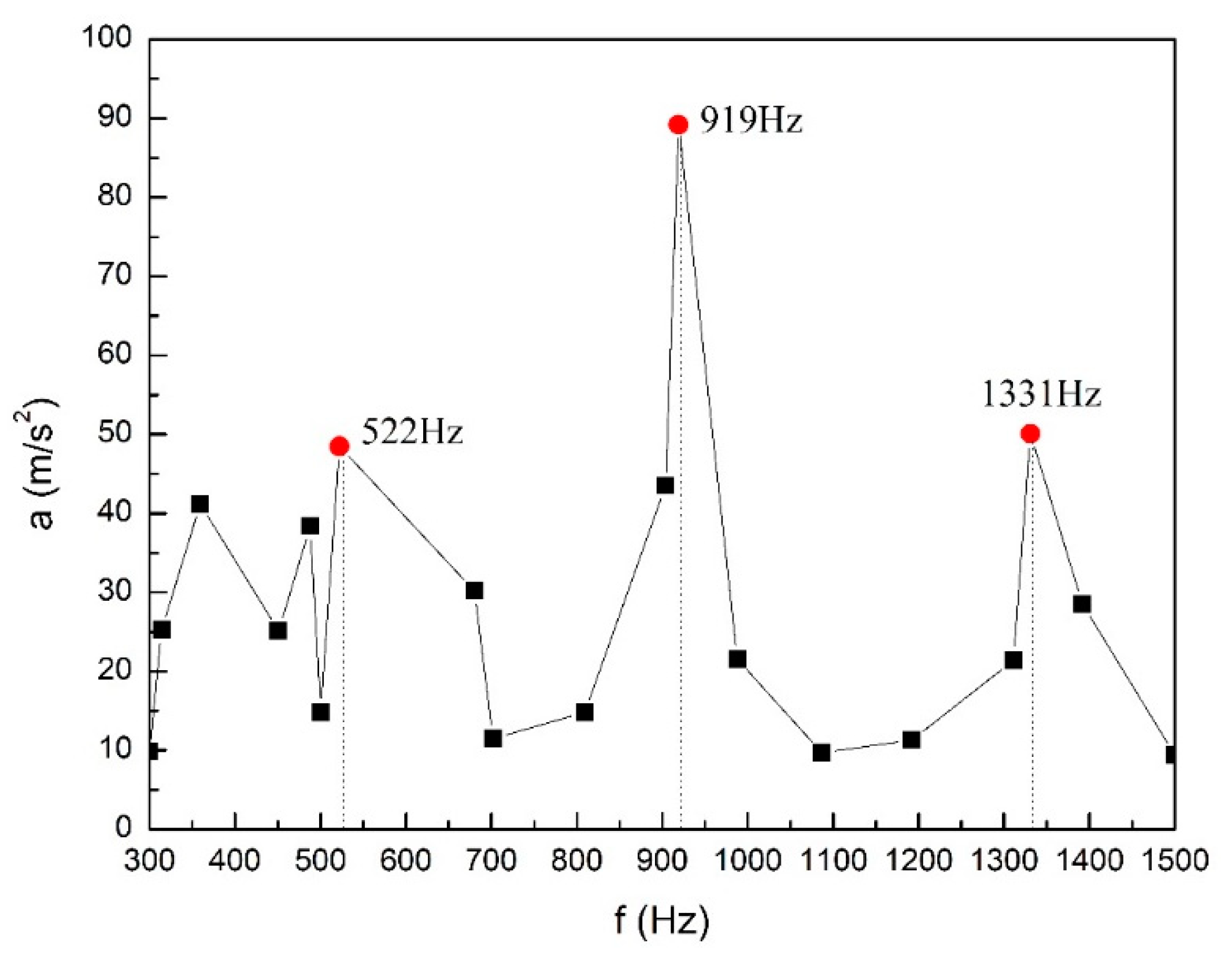
Figure 1 shows a vibration welding platform. During the welding process, the laser beam was perpendicular to the plate. The angle between the blowing pipe and the laser beam was 45° after the welding direction. The laser device was an IPG-YLS-5000 YAG fiber laser (IPG Photonics Corporation, New York, NY, USA) with a rated output power of 5000 W and wavelength of 1.06 μm. The laser mode was continuous wave mode. The vibration system was a self-developed high-frequency vibration platform (Shanghai University of Engineering Science, Shanghai, China) based on magnetostrictive materials, it mainly included a vibration control system and Giant Magnetostrictive Material (GMM) exciter (Shanghai University of Engineering Science, Shanghai, China). The vibration control system consisted of a signal generator, a power amplifier, and an acceleration sensor. The frequency of the vibration platform ranged from 300 to 1500 Hz. A grinding machine (Guangxiang Sampling Co. Ltd., Shanghai, China) was used to grind the oxide scale on the surface of the welded area, then wiped off the oil with acetone reagent. The test plate to be welded was firmly fixed on the vibration platform. The frequency of the vibration platform was searched by means of frequency sweeping and the current was guaranteed to be 2 A during the frequency swept. The frequency sweeping result was plotted as a relationship between frequency and acceleration, as shown in Figure 2. Three resonant frequencies were obtained, which were 522, 919, and 1331 Hz. Pure argon (purity of 99.99%, Air Liquid (China) Investment Co. Ltd., Shanghai, China) was used as the shielding gas, and the gas flow rate was 15 L/min. Bead-on-plate laser welding parameters included laser power (P) of 4000 W, welding speed (v) of 0.02 m/s, and defocusing amount (F) of −15 mm.
3. Results and Discussion
3.1. Welded Bead Microstructure without Vibration and under Vibration
Figure 3 shows the cross-section of welded joint without vibration after bead-on-plate laser welding of Inconel 718 alloy. The upper part of the weld bead is wide and shallow, and the lower part is narrow and deep. It is shaped like a nail. The wide and shallow part of the weld bead is defined as the nail-head and another part of the weld bead is defined as nail-body in this article.
It can be seen from Figure 4a that the weld bead was composed of a cellular crystal area near the fusion line, columnar crystal area, and equiaxed crystal area. “Wheat-head” grains were found in the columnar crystal region. It is found from Figure 4b that some black carbide [18] precipitates appeared between the grain boundaries. As shown in Figure 4c, the crystal grains were preferentially grown along the temperature gradient, and secondary dendrites appeared. As can be seen from Figure 4d, the precipitates in the center of the weld were fine and the distribution was relatively uniform.
Figure 5 shows the microstructure of the Inconel 718 high-frequency micro-vibration bead-on-plate laser welding bead. As shown in Figure 5a, the microstructure distribution of bead-on-plate laser welding under vibration conditions was the same as that in the case of no vibration. It can be seen from Figure 5b that the equiaxed crystal distribution in the center of the weld was uniform. The thin strip-shaped γ″ phase at the grain boundary was denser, while the carbide almost disappeared. The elongated primary dendrites in the columnar crystals were broken and deflected toward both sides of the crystal axis in Figure 5c. Secondary dendrites fell off and were dispersed in the intergranular. Compared with Figure 5d, the cellular crystal area became narrowed and the number of epitaxial growths was reduced. The precipitate at the grain boundary was densely arranged in a grid when there was no vibration.
3.2. SEM Analysis of Laves Phase without Vibration and under Vibration
It can be seen from comparison of Figure 6a,c that the white precipitate Laves phase ((Ni, Cr, Fe)2(Nb, Mo, Ti)) [19] changes little and the distribution is uniform after the vibration. The coarse Laves phase was produced near the fusion line under non-vibration. This is because as the cooling rate increases from the center of the weld to the fusion line, microsegregation occurs in the interdendritic region due to the enrichment of Nb. Since the vibration has the function of stirring the molten pool and accelerating heat transfer, the segregation phenomenon near the fusion line is weakened. That is, the Laves phase under vibration conditions became fine, obviously.
Table 2 shows the element weight fraction increments of the Laves phase under vibration compared to non-vibration. From the elemental weight analysis of Table 2, it is known that the Nb, Ti, and Mo contents in the Laves phase were reduced. In addition to the main elements of the matrix like Ni, Cr, and Fe, the Laves phase also contains Nb, Ti, and Mo elements. This suggests that the Laves phase was reduced under the vibration.
To further explain the reasons for the decrease in the Laves phase, this paper uses forced vibration theory to explain the phenomenon of elemental reduction for laves phase. The vibration that an object generates under the continuous action of a periodic external force (driving force) is called a forced vibration [20]. In this paper, the entire test plate is considered as a single degree of freedom object. The model of forced vibration is used to analyze the vibration of the Inconel 718 test plate. The driving force of the test plate is:
where is the maximum driving force, is the driving angular frequency, and is the time.
The equation of motion for forced vibration is:
where is the mass, is the stiffness coefficient, and is the drag coefficient.
In order to facilitate the derivation of the subsequent formula, the damping factor and the natural angular frequency are introduced.
When the damping of the material is small (i.e., ), the solution of Equation (2) is:
where is the amplitude, is the maximum amplitude, and is the initial phase.
In forced vibration, the periodic driving force supplies energy to the vibration system. On the flip side, the system consumes energy due to damping. If the two are equal, the system reaches a stable vibration state. In the steady vibration state, the frequency of the forced vibration is equal to the frequency of the driving force. When , displacement vibration occurs and the velocity at this time is:
where is the maximum speed as follows:
It is generally believed that under small damped vibration, the angular frequency of forced vibration is equal to the natural angular frequency (i.e., The relationship between the speed and the acceleration of the forced vibration can be simplified for Equation (4):
The average kinetic energy of the test plate due to forced vibration is:
In this paper, the test plates are the same size and δ is constant. It can be seen from formula (8) that at the same vibration frequency and the same time. For the test plate, the kinetic energy generated by the forced vibration is converted into heat energy by the damping internal friction. The heat generated by internal friction of materials due to external vibration causes the temperature of the molten pool to rise and the temperature difference between the two sides of the solid–liquid interface to increase. The steady-state form of plane growth criterion is given by:
where is the temperature gradient, R is the growth rate, is the equilibrium solidification interval, and is the diffusion coefficient. The diffusion coefficient and equilibrium solidification interval ∆T on both sides of the solid and liquid are constant, the decrease in temperature gradient causes the growth rate to reduce. A small amount of solute is discharged to the solid–liquid interface, which causes the interface layer to be depleted of solute. The solid phase that solidified after the growth rate is lowered has a solute content lower than before the decrease. This is the reason for the Laves phase reduction.
Figure 7 shows the Laves phase of the weld zone (S zone in Figure 6c) under different acceleration vibrations. As the vibration acceleration increased, the interdendritic Laves phase was from the coarse reticulate structure to the fine particles. It can be seen from Equations (7)–(9) that, as the acceleration of the vibration increases, the element diffusion rate in the liquid metal increases and the solute solidification rate at the solid–liquid interface decreases. The Mo element was simultaneously dissolved in the austenite. The Nb and Ti elements were sufficiently combined with Ni to form γ′ and γ″ precipitates at high temperatures. Therefore, the segregation and formation rate of the Laves phase were depressed due to a decrease in elements such as Nb surrounded by dendrites
In order to further study the effect of acceleration on the Laves phase, image analysis software was used to semi-quantitatively analyze the Laves precipitation phase generation rate. The SEM original photographs of Figure 8 were selected with pixels of 1280 × 960, dots of 600 DPI per inch, and all SEM images had the same px (relative length). The software analysis content and results are shown in Figure 8. Figure 8a shows the relationship between the area of the Laves phase and the acceleration of vibration. The area of the Laves phase is divided into three levels, and the area below 50 px2 (relative area) is image noise, which is neglected; the Laves phase with an area between 50~100 px2 is relatively small and regular in shape; Laves with an area between 100~500 px2 is relatively large and irregular in shape; the area above 500 px2 is due to the adhesion of the Laves phase. Figure 8b shows the relationship between the average area of the Laves phase, the ratio of the Laves phase area to the total area, and the acceleration of the vibration. As shown in Figure 8a,b, when the acceleration is 15.10 m/s2, the average area and area ratio increase with the growth in number of the fine Laves phases (50~100 px2); At 20.20 m/s2, the fine Laves phases (50~100 px2) adhered to each other during the vibration process and the increase in the average area is caused by the presence of large Laves phase chain blocks. However, the area ratio is slightly lower than acceleration of 15.10 m/s2, which indicates that the Laves phase generation rate is reduced. When the acceleration is 50.10 m/s2, the Laves phase has a significant decrease of the number of particles, the size of the particles, the average area, and the ratio of the total area. As a summary, when the vibration acceleration was 50.10 m/s2, the purpose of reducing the Laves phase generation rate could be achieved.
3.3. Analysis of Liquation Cracks in HAZ
Figure 9 shows the distribution of cracks in the Inconel 718 alloy bead-on-plate laser-welded joint without vibration. Table 3 summarizes the crack distribution of welded joints under different vibration parameters. As can be seen from Figure 9, the cracks were distributed in three different positions of the weld. Some cracks appeared at the HAZ of the nail-head, the nail-body, and the junction of the nail-body and nail-head. The others were distributed in the cellular crystal zone of the nail-body and the junction of the nail-body and nail-head. The length of crack was between 60 and 350 μm, and the crack growth direction was intergranular crack. Combined with the Inconel 718 laser welding thermal cycle and the characteristics and crack distribution morphological characteristics, those cracks that initiated from the HAZ were high temperature liquation cracks [21]. The liquation crack is caused by the re-melting of the low melting eutectic phase γ/Laves in the grain boundaries, and the grain boundary is broken under the tensile stress caused by the solidification shrinkage.
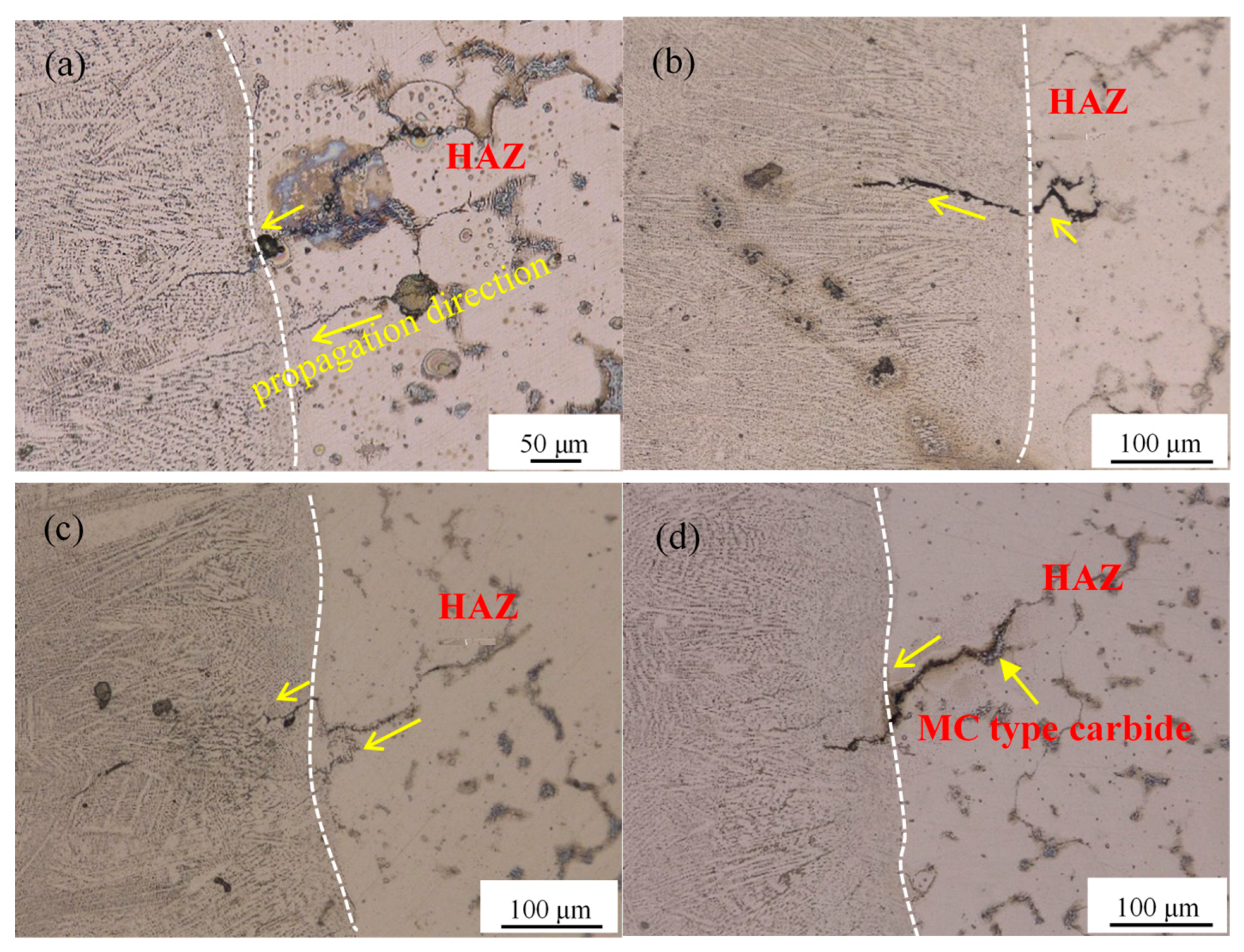
As shown in Figure 10a, the length of liquation crack near the fusion line of the nail-body without vibration was 180 μm. After the vibration was applied, crack length did not change significantly at a vibration frequency of 522 Hz and it was 156 μm, as shown in Figure 10b. When the vibration frequency reached 919 Hz, the crack became narrow and short as shown in Figure 10c, which was 110 μm. When the vibration frequency reached 1331 Hz, the crack propagated up to 200 μm. With the increased of vibration frequency, on the one hand the diffusion of intergranular elements was accelerated, while the segregation among dendrites and the formation of liquid films were reduced; on the other hand, the severe vibration reduced the local stress. The combination of the two made the liquation cracking tendency decreased. This explains the reduction in crack length from 180 to 110 μm. Surprisingly, when the frequency reached 1331 Hz, the crack length increased to 200 μm. The constitutional liquation occurred at the interface between MC type carbide and the substrate according to penetration theory [22], and the undissolved secondary phase and the substrate formed a new liquation film at the interface. Because of the existence of liquefied film, the tendency of cracking is exacerbated. It can be seen from Figure 10d that there is a massive MC type carbide on the crack propagation path, which is why the crack length is increased to 200 μm. Overall, these results indicated that vibration can inhibit the expansion of liquation cracks.
4. Conclusions
In this research, high-frequency micro-vibration-assisted bead-on-plate laser welding of Inconel 718 alloy was investigated. The effects of high-frequency micro-vibration on the microstructure, Laves phase formation, and liquation crack propagation of the Inconel 718 alloy weld were studied. The main findings of this survey are as follows:
- The welding bead after high-frequency micro-vibration is the same as that of non-vibration. The weld was composed of a cellular crystal region, a columnar crystal region, and an equiaxed crystal region. The Laves phases were granular in the center of the weld and uniformly distributed. They were massive and closely distributed near the fusion line.
- Weld grain refinement can be promoted by high-frequency micro-vibration bead-on-plate laser welding of Inconel 718. Fine uniform equiaxed crystal and dispersed γ′, γ″ strengthening phase were obtained. When the vibration acceleration was 50.10 m/s2, the Laves phase of the brittle and hard precipitates between dendrites was effectively reduced. The Laves phase near the fusion line was smaller than that of the non-vibration, and they were independent and evenly distributed.
- It is observed that the cracks are distributed at three locations of the Inconel 718 welded joint. It is found that the liquation crack is located in the HAZ of the nail-head and the nail-body. At the junction of the nail-head and the nail-body, the liquation cracks propagated to the cellular crystal region due to stress concentration, and the liquation cracks propagated to the cellular crystal zone at the nail-body due to the high melting point precipitation phase, like the MC type carbide.
- High temperature liquation cracks occurred in the HAZ of the Inconel 718 alloy laser-welded joints, and liquation cracks can be inhibited by adding vibrations of appropriate frequency. In this test, the optimal vibration frequency was 919 Hz, which can inhibit the crack propagation, and crack length was 110 μm. When the vibration frequency reached 1331 Hz, the crack propagation was extended and the crack length was 200 μm. The crack width became larger, especially at the MC type carbide.
Author Contributions
Resources, Q.L., H.Y. and P.Z.; writing—original draft preparation, Y.B.; investigation, X.R.
Funding
This research was funded by National Natural Science Foundation of China, grant number No. 51605276.
Conflicts of Interest
The authors declare no conflict of interest.
References
- Huang, C.A.; Wang, T.H.; Lee, C.H.; Han, W.C. A study of the heat-affected zone (HAZ) of an Inconel 718 sheet welded with electron-beam welding (EBW). Mater. Sci. Eng. A 2005, 398, 275–281. [Google Scholar] [CrossRef]
- Ola, O.T.; Doern, F.E. A study of cold metal transfer clads in nickel-base INCONEL 718 superalloy. Mater. Des. 2014, 57, 51–59. [Google Scholar] [CrossRef]
- Mortezaie, A.; Shamanian, M. An assessment of microstructure, mechanical properties and corrosion resistance of dissimilar welds between Inconel 718 and 310S austenitic stainless steel. Int. J. Press. Vessel. Pip. 2014, 116, 37–46. [Google Scholar] [CrossRef]
- Odabasi, A.; Unlu, N.; Goller, G.; Eruslu, M.N. A study on laser beam welding (LBW) technique: Effect of heat input on the microstructural evolution of superalloy Inconel 718. Metall. Mater. Trans. A 2010, 41, 2357–2365. [Google Scholar] [CrossRef]
- Qu, F.S.; Liu, X.G.; Fei, X.; Zhang, K.F. High temperature tensile properties of laser butt-welded plate of Inconel 718 superalloy with ultra-fine grains. Trans. Nonferrous Met. Soc. China 2012, 22, 2379–2388. [Google Scholar] [CrossRef]
- Ling, W.; He, G.; Haofeng, Z.; Jianxin, D.; Maicang, Z. Phase transformation and liquid density redistribution during solidification of Ni-based superalloy Inconel 718. Res. Dev. 2012, 9, 3. [Google Scholar]
- Lertora, E.; Mandolfino, C.; Gambaro, C. Mechanical behaviour of Inconel 718 Thin-walled laser welded components for aircraft engines. Int. J. Aerosp. Eng. 2014, 1–9. [Google Scholar] [CrossRef]
- Tharappel, J.T.; Babu, J. Welding processes for Inconel 718-A brief review. In Hyderabad: International Conference on Recent Advances in Materials, Mechanical and Civil Engineering; IOP Publishing: Bristol, UK, 2017. [Google Scholar]
- Sidharth, D.; KV, P.P.; Rajendran, R.; Narayanan, S. Microstructure and properties of inconel 718 and AISI 416 laser welded joints. J. Mater. Process. Technol. 2019, 266, 52–62. [Google Scholar]
- Jose, M.J.; Kumar, S.S.; Sharma, A. Vibration assisted welding processes and their influence on quality of welds. Sci. Technol. Weld. Join. 2016, 21, 243–258. [Google Scholar] [CrossRef]
- Wu, W. Influence of vibration frequency on solidification of weldments. Scr. Mater. 2000, 42, 661–665. [Google Scholar] [CrossRef]
- Qinghua, L.; Ligong, C.; Chunzhen, N. Effect of vibratory weld conditioning on welded valve properties. Mech. Mater. 2008, 40, 565–574. [Google Scholar] [CrossRef]
- Sakthivel, P.; Sivakumar, P. Effect of vibration in tig and arc welding using Aisi316 stainless steel. Inter. J. Eng. Res. Sci. Technol. 2014, 3, 116–130. [Google Scholar]
- Singh, J.; Singh, B.; Singh, S.P.; Naim, M. Investigation of Performance Parameters of PMSM Drives using DTC-SVPWM Technique. In 2012 Students Conference on Engineering and Systems; Institute of Electrical and Electronics Engineers: Piscataway, NJ, USA, 2012; pp. 1–6. [Google Scholar]
- Anbarasan, N.; Narein, N.; Jerome, S. Influence of mechanical arc oscillation on the microstructural and mechanical properties of Inconel 718 welds. Trans. Indian Inst. Met. 2019, 72, 1541–1544. [Google Scholar] [CrossRef]
- Wang, Z.L.; Zheng, Z.T.; Zhao, L.B.; Lei, Y.F.; Yang, K. Microstructure evolution and nucleation mechanism of Inconel 601H alloy welds by vibration-assisted GTAW. Int. J. Miner. Metall. Mater. 2018, 25, 788–799. [Google Scholar] [CrossRef]
- Thavamani, R.; Balusamy, V.; Nampoothiri, J.; Subramanian, R.; Ravi, K.R. Mitigation of hot cracking in Inconel 718 superalloy by ultrasonic vibration during gas tungsten arc welding. Alloy. Compd 2018, 740, 870–878. [Google Scholar] [CrossRef]
- Bor, H.Y.; Chao, C.G.; Ma, C.Y. The influence of magnesium on carbide characteristics and creep behavior of the MAR-M247 superalloy. Scr. Mater. 1998, 38, 329–335. [Google Scholar] [CrossRef]
- Chen, Y.; Zhang, K.; Huang, J.; Hosseini, S.R.E.; Li, Z. Characterization of heat affected zone liquation cracking in laser additive manufacturing of Inconel 718. Mater. Des. 2016, 90, 586–594. [Google Scholar] [CrossRef]
- Britton, B.W.G. Vibration Theory and its Applications. Phys. Bull. 1967, 18, 117. [Google Scholar] [CrossRef]
- Chen, Y.; Lu, F.; Zhang, K.; Nie, P.; Hosseini, S.R.E.; Feng, K.; Li, Z.; Chu, P.K. Investigation of dendritic growth and liquation cracking in laser melting deposited Inconel 718 at different laser input angles. Mater. Des. 2016, 105, 133–141. [Google Scholar] [CrossRef]
- Duvall, D.S. Further heat affect zone studies in heat resistant nickel alloys. Weld. J. 1967, 46, 423–432. [Google Scholar]
Figure 1.
Schematic diagram of welding platform.

Figure 2.
The relation curve of frequency (f) and vibration acceleration (a).

Figure 3.
Cross-section of welded joint (P = 4000 W, v = 0.02 m/s).

Figure 4.
The welded bead microstructure of bead-on-plate laser welding without vibration (P = 4000 W, v = 0.02 m/s): (a) Weld seam; (b) fusion line and cellular crystal zone; (c) columnar crystal zone; and (d) equiaxed crystal zone.
Figure 4.
The welded bead microstructure of bead-on-plate laser welding without vibration (P = 4000 W, v = 0.02 m/s): (a) Weld seam; (b) fusion line and cellular crystal zone; (c) columnar crystal zone; and (d) equiaxed crystal zone.

Figure 5.
The welded bead microstructure of bead-on-plate laser welding under vibration (P = 4000 W, v = 0.02 m/s, a = 50.10 m/s2, f = 1331 Hz): (a) Weld seam; (b) equiaxed crystal zone; (c) columnar crystal zone, region S is selected for subsequent SEM analysis; and (d) cellular crystal zone.
Figure 5.
The welded bead microstructure of bead-on-plate laser welding under vibration (P = 4000 W, v = 0.02 m/s, a = 50.10 m/s2, f = 1331 Hz): (a) Weld seam; (b) equiaxed crystal zone; (c) columnar crystal zone, region S is selected for subsequent SEM analysis; and (d) cellular crystal zone.

Figure 6.
The composition of the Laves phase near the fusion line (P = 4000 W, v = 0.02 m/s). (a,b) f = 0 Hz; (c,d) f = 1331 Hz.
Figure 6.
The composition of the Laves phase near the fusion line (P = 4000 W, v = 0.02 m/s). (a,b) f = 0 Hz; (c,d) f = 1331 Hz.

Figure 7.
The influence of acceleration on precipitated phase (P = 4000 W, v = 0.02 m/s, f = 1331 Hz): (a) 0 m/s2; (b) 15.10 m/s2; (c) 20.20 m/s2; (d) 50.10 m/s2.
Figure 7.
The influence of acceleration on precipitated phase (P = 4000 W, v = 0.02 m/s, f = 1331 Hz): (a) 0 m/s2; (b) 15.10 m/s2; (c) 20.20 m/s2; (d) 50.10 m/s2.

Figure 8.
Analysis of Laves precipitation phase generation rate. (a) The relationship between the number of different Laves phase areas and the acceleration (a) of vibration; (b) the relationship between the average area of the Laves phase, the ratio of total area, and the acceleration (a) of vibration.

Figure 9.
Cracks distribution in Inconel 718 alloy laser weld (P = 4000 W; v = 0.02 m/s): (a) Cracks at the nail-head; (b,c) cracks on the junction of the nail-body and nail-head; (d–f) cracks at the nail-body; and (g)welded joint.
Figure 9.
Cracks distribution in Inconel 718 alloy laser weld (P = 4000 W; v = 0.02 m/s): (a) Cracks at the nail-head; (b,c) cracks on the junction of the nail-body and nail-head; (d–f) cracks at the nail-body; and (g)welded joint.

Figure 10.
Liquation crack at different vibration frequencies of welded joint (P = 4000 W; v = 0.02 m/s): (a) 0 Hz; (b) 522 Hz; (c) 919 Hz; (d) 1331 Hz.
Figure 10.
Liquation crack at different vibration frequencies of welded joint (P = 4000 W; v = 0.02 m/s): (a) 0 Hz; (b) 522 Hz; (c) 919 Hz; (d) 1331 Hz.


Table 1.
Chemical composition of Inconel 718 nickel-based superalloy (wt. %).
| Ni | Cr | Mo | Nb | Co | Cu | Mn | Si |
|---|---|---|---|---|---|---|---|
| 50–55 | 17–21 | 2.8–3.3 | 4.75–5.5 | 1 | 0.3 | 0.35 | 0.35 |
| Al | Ti | B | P | S | C | Fe | - |
| 0.2–0.8 | 0.7–1.15 | ≤0.006 | ≤0.01 | ≤0.01 | ≤0.08 | Balance | - |
Table 2.
The element component of the Laves phase near the fusion line under vibration (P = 4000 W, v = 0.02 m/s, a = 50.10 m/s2, 1331 Hz).
Table 2.
The element component of the Laves phase near the fusion line under vibration (P = 4000 W, v = 0.02 m/s, a = 50.10 m/s2, 1331 Hz).
| Element | Ni | Cr | Fe | Nb | Mo | Ti | Al | C | Cu |
|---|---|---|---|---|---|---|---|---|---|
| wt. (%) | 40.82 | 17.41 | 15.03 | 15.12 | 5.65 | 1.71 | 1.24 | 1.25 | 1.77 |
| Increase than non-vibration (%) | 6.35 | 3.4 | 3.84 | −11.91 | −3.2 | −0.18 | 0.76 | 0.58 | 0.01 |
Table 3.
The crack distribution under different vibration parameters.
| Vibration Situation | Crack | Crack at the Location of the Welded Joint | Specific Location in Weld | Length |
|---|---|---|---|---|
| No vibration | Yes | Nail-head and nail-body intersection | from HAZ to cellular crystal zone | 125 μm |
| Nail-body | from HAZ to cellular crystal zone | 85 μm | ||
| f = 522 Hz | Yes | Nail-head and nail-body intersection | HAZ | 79 μm |
| Nail-body | cellular crystal zone | 112 μm | ||
| Nail-body | HAZ | 155 μm | ||
| No | - | - | None | |
| f = 1331 Hz | Yes | Nail-body | from HAZ to cellular crystal zone | 355 μm |
| Yes | Nail-head | HAZ | 162 μm | |
| Nail-head and nail-body intersection | HAZ | 156 μm | ||
| Nail-body | HAZ | 69 μm | ||
| Yes | Nail-body | from HAZ to cellular crystal zone | 356μm |
© 2019 by the authors. Licensee MDPI, Basel, Switzerland. This article is an open access article distributed under the terms and conditions of the Creative Commons Attribution (CC BY) license (http://creativecommons.org/licenses/by/4.0/).
Share and Cite
MDPI and ACS Style
Bai, Y.; Lu, Q.; Ren, X.; Yan, H.; Zhang, P. Study of Inconel 718 Welded by Bead-On-Plate Laser Welding under High-Frequency Micro-Vibration Condition. Metals 2019, 9, 1335. https://0-doi-org.brum.beds.ac.uk/10.3390/met9121335
AMA Style
Bai Y, Lu Q, Ren X, Yan H, Zhang P. Study of Inconel 718 Welded by Bead-On-Plate Laser Welding under High-Frequency Micro-Vibration Condition. Metals. 2019; 9(12):1335. https://0-doi-org.brum.beds.ac.uk/10.3390/met9121335
Chicago/Turabian StyleBai, Yongzhen, Qinghua Lu, Xinhuai Ren, Hua Yan, and Peilei Zhang. 2019. "Study of Inconel 718 Welded by Bead-On-Plate Laser Welding under High-Frequency Micro-Vibration Condition" Metals 9, no. 12: 1335. https://0-doi-org.brum.beds.ac.uk/10.3390/met9121335
Note that from the first issue of 2016, this journal uses article numbers instead of page numbers. See further details here.