Power Spinning of the Curved Head with Tailor Welded Aluminum Alloy Blank: Deformation, Microstructure, and Property

1
Sichuan Aerospace Changzheng Equipment Manufacturing Corporation, Chengdu 610100, China
2
Shaanxi Key Laboratory of High-Performance Precision Forming Technology and Equipment, State Key Laboratory of Solidification Processing, School of Materials Science and Engineering, Northwestern Polytechnical University, Xi’an 710072, China
*
Authors to whom correspondence should be addressed.
Metals 2019, 9(12), 1359; https://0-doi-org.brum.beds.ac.uk/10.3390/met9121359
Submission received: 22 November 2019
/
Revised: 9 December 2019
/
Accepted: 10 December 2019
/
Published: 17 December 2019
Abstract
:The power spinning of tailor-welded blank (TWB) provides a feasible way to form the large-scale curved heads of aluminum alloy. However, the inhomogeneous material property of TWB produces different and more complex spinning behaviors compared with the traditional spinning of an integral homogenous blank. In this research, the deformation characteristics, microstructure, and the properties of the power spun curved head with aluminum alloy TWB were studied. A finite element model considering the inhomogeneous material property of welded blank is developed for the analysis of the power spinning process. To conduct accurate and efficient simulation, an effective meshing method is proposed according to the feature of TWB. The simulation and experimental results show that the weld zone (WZ) presents the larger equivalent stress but smaller equivalent strain than base material zone (BMZ) in power spinning due to its larger deformation resistance. Under the combined effects of the spiral local loading path and inhomogeneous deformability of TWB, the equivalent strain near the weld zone has an asymmetric V-shaped distribution. Strain inhomogeneity gradually increases with deformation and leads to an increase of the flange swing degree. In addition, the circumferential thickness distribution is relatively uniform, which is little affected by the existence of the weld line. However, the circumferential unfitability distribution becomes non-uniform and the roundness is worsened due to the existence of the weld line. Compared to the initial blank, the microstructure in WZ and BMZ are both elongated after spinning. The tensile strength is improved but plasticity reduced after power spinning based on the circumferential and radial tests of WZ and BMZ. The results are of theoretical and technical guidance for the power spinning of the curved head component with TWB.
1. Introduction
The surface heads of aluminum alloy are widely used as a key component for pressure vessels in the aerospace field to satisfy the high demand for performance, as they are lightweight, and are low cost. These components are usually formed by spinning technology, which has the advantages of low forming load, simple tooling, and high efficiency [1,2]. With the rapid development of high-end equipment in aerospace, the larger scale head component is growing in need. The diameter of the pressure vessel in the latest heavy-lift launch vehicle is greater than 5 m. However, it is difficult to obtain a high-quality integral blank with a large size in this order by rolling directly. This limits the high-performance spinning forming of large-scale heads. Fortunately, the development of welding technology, especially friction stir welding (FSW), has improved the weld quality of aluminum alloy effectively in recent years [3,4,5,6,7]. Thus, it may be a feasible way to form the aluminum alloy large-scale heads by the power spinning of tailor welded blank (TWB).
The power spinning of the large-scale curved head with TWB is a very complex forming process. The curved surface of the head component usually possesses a complicated profile, for example, a combination of a spherical surface, conical surface, ellipsoid surface, and so on, which makes the half cone angle change, largely during spinning. The material undergoes large localized uneven deformation under complex stress state. Moreover, the different deformation behavior between the weld joint and base parent material would intensify the deformation inhomogeneity in spinning. Generally, the weld joint by FSW presents higher strength than the base material, which may produce a constraining effect on the whole deformation. It may further lead to different deformation characteristics, microstructure, and properties compared to the spinning of the integral homogenous blank [8,9]. Therefore, it is of great importance to investigate the deformation characteristics and forming quality in the power spinning of the aluminum alloy curved head with TWB.
At present, quantities of studies have been conducted on the deformation characteristics and forming rules in the power shear spinning and conventional spinning of the integral blank. Zhang et al. [10] developed a finite element (FE) model for the power spinning of large ellipsoidal heads with variable thicknesses. Based on this model, they analyzed the distributions of stress, strain, and wall thickness during the forming process, and the unfitability and radial runout of the spun head. Zhan et al. [11] studied the variation of stress and strain and the wall thickness distribution during the shear spinning of a cone part through FE simulation. In addition, they also studied the effect of feed ratio on the tool forces and geometrical tolerances of produced parts [12]. Zhang et al. [13] investigated the effects of processing parameters on the forming quality in the conventional spinning of a thin-walled aluminum alloy head. Gan et al. [14] analyzed the features of stress, strain, and wall thickness uniformity under different roller paths in the conventional spinning of aluminum hemispherical parts. However, because of the heterogeneous material property of welded blank, the deformation characteristics and distribution of stress and strain, especially near the weld zone, may present different rules during the power spinning of TWB. Moreover, it may also lead to non-uniform microstructure and mechanical properties, then affecting the service performance of the spun component.
In recent years, aluminum alloy TWB is getting more and more applications in sheet plastic forming. Heo et al. [15] characterized the weld zone movement in the deep drawing of SPC1 alloy TWB and studied the effect of drawbead dimension on the weld zone movement. Liu et al. [16] and Wang et al. [17] studied the weld zone movement, strain distribution, and failure modes under different forming conditions in the hot stamping of AA6082 TWB. However, they do not consider the various forms of deformation behavior amongst different zones in TWB. Lee et al. [18] evaluated the formability performance of AA6111 aluminum alloy TWB by FSW based on the limit dome height obtained by hemispherical dome stretch tests and compared to that of the base material. Habibi et al. [19] experimentally investigated the mechanical properties, formability, and forming limit diagrams of the TWB with different thicknesses. Both of the above two works found that the formability performance of the TWB sheet is different from that of the base material, moreover, which is dependent on the arrangement direction, ductility, and strength of the weld zone. They also suggested that much attention should be paid to the precise material characterization of the weld zone and elaborate design of weld zone arrangement in the real plastic forming with TWB. Considering the difference of material properties between weld zone and base material, Ren et al. [20] studied the deformation characteristics during the bending of welded tubes by FE simulation and experiment. They quantitatively evaluated the constraining effects of the weld zone on strain distributions and its dependence on the location of the weld zone. Mennecart et al. [21] studied the influence of the weld zone on fracture failure during deep drawing of high strength TWB compared to that of the integral blank. However, the deformation characteristics of power spinning are quite different from those of tube bending and deep drawing, where the effect of the weld zone may also be quite different. Thus, it is still needed to study the deformation characteristics and forming quality in the power spinning of aluminum alloy curved head with TWB.
In this paper, an FE model for the power spinning of the curved head with aluminum alloy TWB is first developed and validated. It considers the differences of material properties in weld nugget zone (WNZ), heat affected zone (HAZ), and base material zone (BMZ). Based on the FE model, the deformation characteristics, especially near the weld zone (WZ), during the power spinning of TWB are analyzed. The wall thickness, unfitability, microstructure, and mechanical properties of the formed component are investigated. The results could provide technical guidance for the spinning of the curved head component with TWB.
2. Material and Method
2.1. Material and Curved Head Component
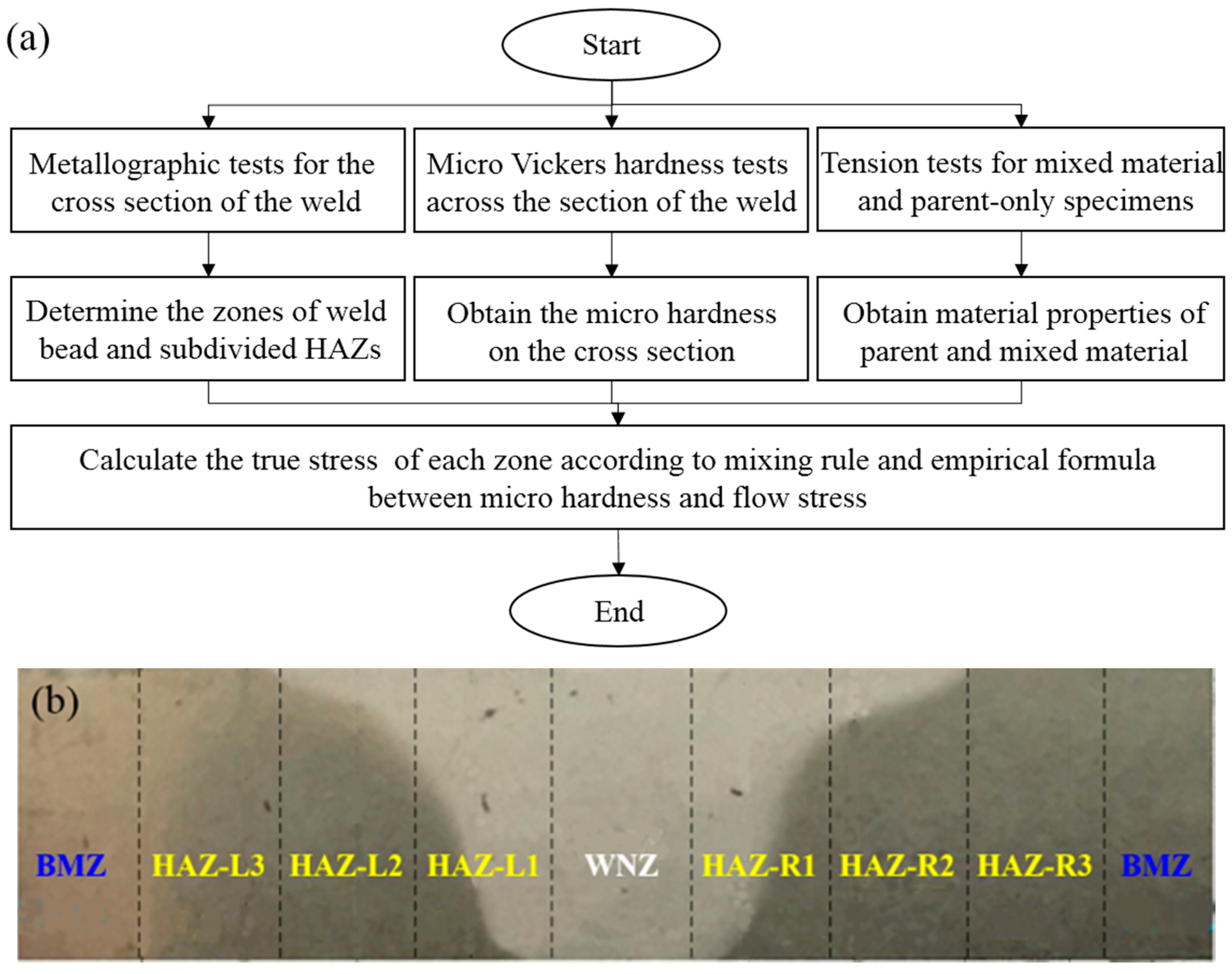
The material used in this study is a 2219 aluminum alloy welded plate with a thickness of 2 mm. It is produced from the flat sheet by the FSW process. It is conducted on an FSW-LM-BS08 mechanical machine at room temperature. The welding speed and rotational speed are 180 mm/min and 800 r/min, respectively. As well known, the welding process will produce different microstructure and properties at the weld zone (WZ) from the base material zone (BMZ). It is very critical to precisely characterize their properties to analyze the deformation behavior during the plastic forming of TWB. Ren et al. [22] and Xing et al. [23] have proposed an effective method to evaluate the property of WZ including the weld nugget zone (WNZ) and heat-affected zone (HAZ), and establish the corresponding constitutive model, as shown in Figure 1a. According to their method, the material properties of 2219 aluminum alloy TWB was evaluated and molded. In this work, the width of WZ is 14 mm, which is divided into seven sub-regions with the same width of 2 mm, i.e., WNZ and six HAZ, as shown in Figure 1b. Then, the constitutive model of different regions was fitted by the Hollomon equation (). Table 1 lists the tested mechanical properties of different regions in TWB. Figure 2 shows the determined stress-strain curves of different regions in TWB.
Figure 3 shows the schematic of the target curved head component. Its height in the y-axis is 100.43 mm, and the diameter of the large end is 390.78 mm. Its interior surface generatrix can be divided into two segments: the arc segment and the linear segment. The arc segment can be described by the following equation:
The linear segment is tangential to the arc segment with a half cone angle of 50°, as shown in Figure 3. The wall thickness decreases along the negative direction of the y-axis in accordance with the sine law.
2.2. FE Modelling of the Power Spinning with TWB
The FE model for power spinning of TWB was established using the ABAQUS/Explicit, as shown in Figure 4. The thickness and diameter of the blank are 2 mm and 400 mm, respectively. It is defined as deformable-body and discretized as four-node doubly curved thin quadrilateral shell elements (S4R). The whole blank is divided into WNZ, six HAZ sub-regions, and BMZ according to the division in Figure 1b. Their material models are assigned according to the data in Figure 2. The mandrel and roller are set as rigid bodies. The tie constraint is set between the blank bottom and mandrel to ensure that the blank can rotate with the mandrel. Coulomb’s friction model is applied to describe the friction behavior between tools and blank. After spinning, the ABAQUS/Standard module was used to simulate the spring-back process. The roller path is the typical shear forming path according to the law of sines and the other main processing parameters are given in Table 2.
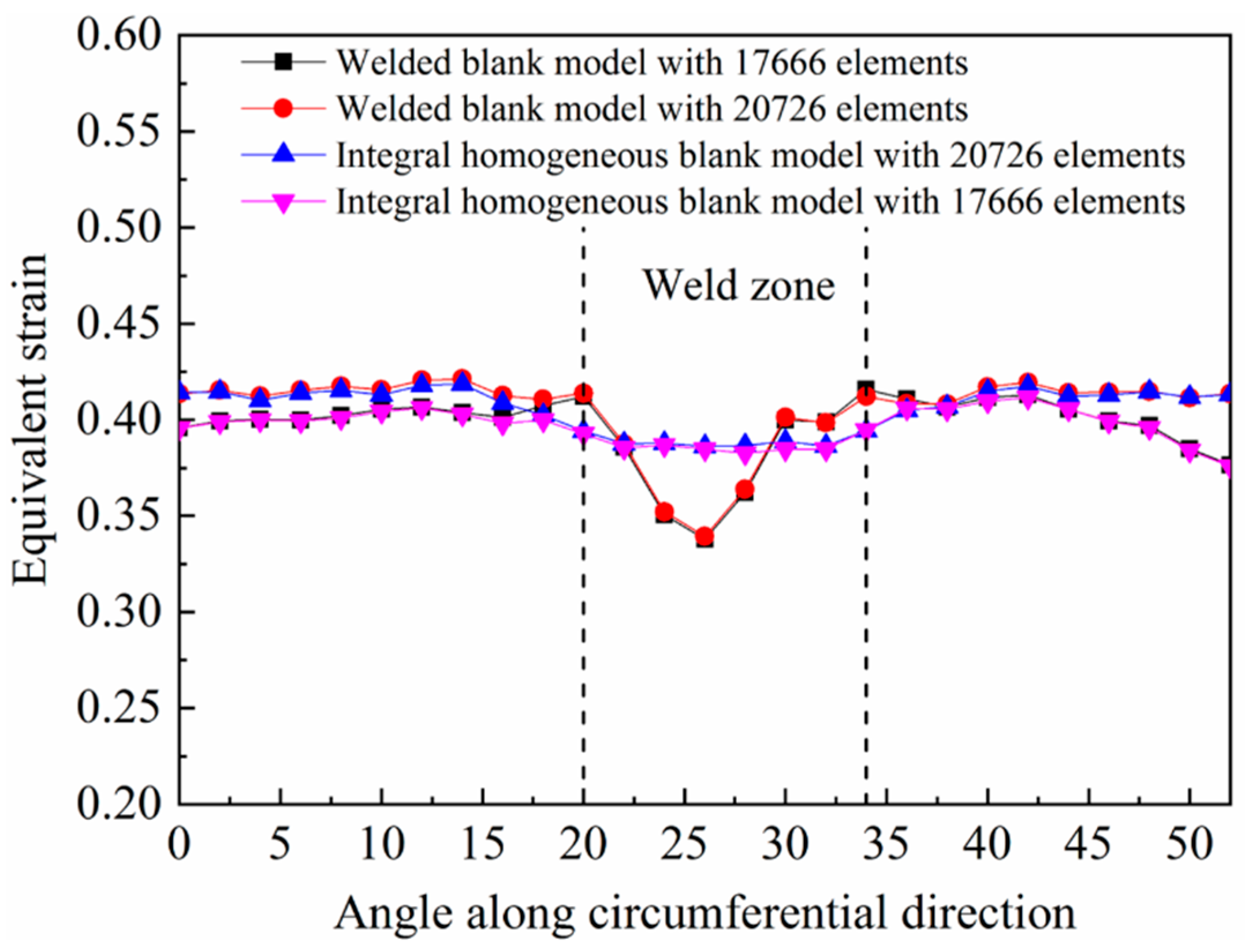
It should be noted that due to the significant variation of the material model near WZ, reasonable element meshing is required to get high simulation precision and efficiency simultaneously. To this end, we proposed a meshing method, as shown in Figure 5. The WZ is locally meshed with 7 elements in the circumferential direction, which correspond to the WNZ and six HAZ, respectively. The radial side length of these elements are all the same. As for the BMZ, it is separated into four quadrant regions by the weld line and its perpendicular line. The same meshing method is applied to the four quadrant regions. For each quadrant region, it is subdivided into four annular regions and three transitional regions. The sweep method is applied to generate meshes in annular regions. While, the seed number increases from the interior to the exterior, which are coordinated by three transitional regions with free element meshing. The radial side length of the element in BMZ is the same as that in WZ. However, the circumferential side length of the element in BMZ increases gradually from the side near WZ to the side far away WZ, which is intended to guarantee the smooth transition from fine mesh to coarse mesh. It is well known that enough mesh number, i.e., enough small mesh size, is required to get higher simulation accuracy. To get a reasonable mesh number, we compared the simulation results at different mesh numbers to analyze the mesh sensitivity. Figure 6 shows the simulated equivalent strains (PEEQ) near the WZ of two models with 20,726 and 17,666 elements. In addition, two integral homogenous blank FE models with the same meshing method were also developed to check whether the meshing method will produce error itself. It can be found that the simulation results are very close to the two models with 20,726 and 17,666 elements. The simulated PEEQ at different circumferential positions are also very close presenting no mesh-dependence for the FE model of the homogenous blank. These indicate that the proposed meshing method and 20,726 elements are applicable to get reliable simulation results for the spinning of TWB in this work.
2.3. Experimental Validation of the FE Model
The spinning experiment at the conditions in Table 2 was conducted to verify the developed FE model, as shown in Figure 7. It can be found that the simulated workpiece shape closely matches the experimental result. In addition, the profile and wall thickness distribution of the formed components were measured, as shown in Figure 8. It can be seen from Figure 8a that the simulated profile agrees well with the experimental result. The average and maximum relative errors are 0.53% and 2.74%, respectively. Figure 8b and c show the comparisons of thickness distribution along generatrix in WZ and circumferential direction, respectively. The average and maximum relative errors are 4.50% and 7.08%, respectively. These suggest that the established FE model for the power spinning of the curved head with TWB has a high prediction accuracy.
3. Results and Discussion
3.1. Deformation Characteristics
Figure 9 shows the comparisons of typical distributions of equivalent stress and strain at welded and homogeneous workpieces during power spinning. It can be found that the welded and homogeneous workpieces present a very close distribution feature in BMZ. Both of equivalent stress and strain present the annular distribution feature. Moreover, they both increase with the radial direction and reach the maximum in the annular zone behind roller. These features are the same as those in the common power spinning of the curved head, which have been explained in reference [10]. However, the distributions of equivalent stress and strain in WZ are quite different from the BMZ, as shown in Figure 9a,b. The WZ presents larger stress but smaller strain than BMZ. As shown in Figure 2, the deformation resistance of WZ is greater than BMZ, thus the equivalent stress in WZ is larger. As for the distribution feature of equivalent strain near WZ, it will be analyzed in detail below.
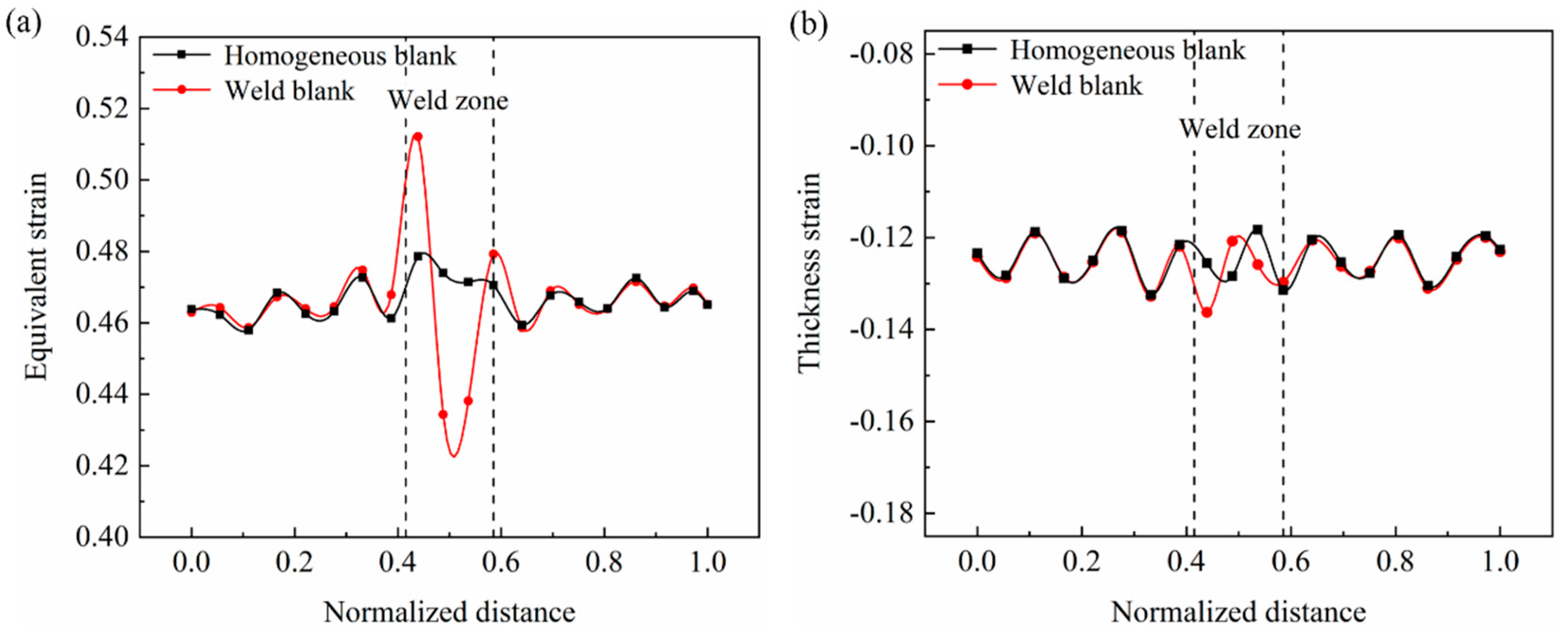
Figure 10 shows the circumferential distributions of equivalent strain and strain components near WZ. It can be seen from Figure 10a that the distribution of equivalent strain near WZ presents a V-shaped feature. The equivalent strains at two boundaries between WZ and BMZ are larger than the values of the homogeneous workpiece. While the equivalent strain at the middle of WZ is smaller than that of the homogeneous workpiece. In addition, it should be noted that the distribution of equivalent strain in WZ is asymmetric. The left boundary presents a larger strain than the right boundary, as shown in Figure 10a. From the distributions of three strain components (Figure 10b–d), it can be seen that thickness and circumferential strains both present a similar distribution feature to equivalent strain, i.e., larger at boundaries and smaller at the center. However, the radial strain changes little near WZ and is very close to that of the homogeneous workpiece. These suggest that the V-shaped distribution of equivalent strain near WZ is mainly caused by the thickness and circumferential strains, while little related to the radial strain.
To explain the V-shaped distribution feature of equivalent strain, the deformation behavior near WZ was analyzed. Figure 11a shows the schematic of deformation behavior when the roller is about to contact the WZ. The material in the roller acting zone will move in the vertical direction and deform, meanwhile, the material in front of the roller will also passively move vertically a little. They will restrain each other. Figure 11b shows the distribution of vertical velocity in the deformation region under different conditions. It can be observed that when encounters BMZ, the velocity in the front of the roller is close to that in the roller acting zone. However, when encountering the WZ, the velocity in front of the roller is much smaller than that in the roller acting zone and close to 0. This is because the deformation resistance of WZ is larger than that of BMZ, which will lead to larger resistance to the passive vertical movement. This discordant movement caused by incompatible deformability in two zones will cause larger equivalent strain at the boundary between BMZ and WZ, i.e., the left boundary in Figure 10a. On the contrary, when the roller moves from WZ to BMZ, the BMZ in front of the roller possesses good deformability, which can coordinate the deformation in the roller acting zone. Thus, the equivalent strain at the right boundary in Figure 10a is smaller than that at the left boundary, presenting the asymmetric features. On the other hand, when the whole deformation region locates in WZ, the deformability difference between the roller acting zone and front of the roller is very small. Moreover, the deformation resistance of WZ is larger than that of BMZ. Thus, the equivalent strain in the center of WZ is smaller than that in BMZ.
The above analyses suggest that the spiral local loading path of the roller and inhomogeneous deformability of the welded blank results in the uneven strain distribution near the WZ. In this work, the difference between the maximum and minimum strains in a circle (cross-section) is applied to evaluate the deformation inhomogeneity degree (DI), as indicated by
DI = εmax − εmin
Figure 12 shows the variation of DI during the forming process of TWB. It can be found that the DI increases gradually with the forming process. This may be related to the deformability difference between the WZ and BMZ increasing with strain, as shown in Figure 2.
As well known, the flange state plays a great role in the forming quality during spinning. Thus, the flange swing degree (FSD) during the forming process is also analyzed, which is evaluated by the difference between the peak and valley points on the flange. From Figure 13, it can be found that FSD first increases quickly, then change little, and increases quickly again in the last forming stage. This variation trend is very close to that of DI in Figure 12, which suggests that the deformation inhomogeneity has an important effect on the FSD. Besides, it can be seen that the FSD is very close to the spinning of the welded and homogeneous blank. It indicates that the inhomogeneous material properties of welded blank do not intensify the FSD in this work.
3.2. Wall Thickness and Unfitability Distribution
As the wall thickness and unfitability are two critical indexes for the forming quality of power spinning, their distributions in four typical paths on the workpiece were analyzed in this section. Figure 14 shows the typical analysis paths. Path 1 and 2 are two circumferential paths in the arc and linear segments, respectively. Path 3 and 4 are two radial paths along WZ and its perpendicular direction, respectively.
Figure 15a,b shows the wall thickness distribution along typical circumferential and radial paths, respectively. It can be seen that the wall thickness at two circumferential paths are both close to the ideal sine reduction rate. In addition, the wall thickness distribution is almost uniform in the circumferential direction, except for a slight fluctuation near the WZ. The wall thickness in the WZ presents an approximate ∧-shaped distribution. The thicknesses near the boundaries are smaller than that in the BMZ, but those in the center are greater. This is caused by the V-shaped inhomogeneous distribution of equivalent strain in the WZ, as described in Section 3.1. There is an obvious negative correlation between wall thickness and equivalent strain. However, it should be noted that this thickness fluctuation is very small compared to the thickness variation in the radial direction. As shown in Figure 15b, the wall thickness in the WZ (Path 3) and BMZ (Path 4) are very close. This suggests that as far as the wall thickness be considered, the existence of WZ hardly affects the thickness homogeneous. As for the dramatic increase of thickness at the edge of the component, it has also been found in the work of [10], which is a common phenomenon in the power spinning. This is because the flange width is very small at the final forming stage, which makes the flange fluctuate greatly and present a very small constraint effect. Under these effects, the deformation mode will deviate the ideal shear deformation. Thus, the wall thickness increases dramatically at the edge of the component. However, this part can be cut after forming, which has little effect on the forming quality.
To analyze the unfitability characteristic, the unfitability degree (UD) proposed by [24] is applied in this work:
where, (x, y, z) is the coordinate of node i and ti is the thickness at node i. The first and second equations are applied to the arc and linear segments, respectively. Figure 16 shows the distribution of UD along radial paths. It can be found that the UD increases first then decreases for both radial paths. Besides, it can be observed that the UD in the WZ (Path 3) is larger than that in the BMZ (Path 4) for smaller radial distances, while it gets smaller for larger radial distances. These indicate that the existence of the weld line leads to the non-uniformity of UD in the circumferential direction, which will also worsen the roundness of formed components to some extent.
3.3. Microstructure and Mechanical Properties
In this section, the microstructure and mechanical properties of spinning formed components are analyzed. The microstructure was observed with the magnification of 500× using an optical microscope. Figure 17 shows the initial and deformed microstructure in the BMZ and WZ. It can be seen that the aspect ratio of grains in deformed microstructure is much greater than the initial microstructure for both of the BMZ and WZ. This is caused by the significant shear deformation in power spinning. The significant microstructure change will affect the final mechanical properties. Besides, it can be observed that the deformed microstructure in the WZ and BMZ are quite different, which may lead to the inhomogeneous distribution of mechanical property in the formed workpiece. Thus, the mechanical properties in BMZ and WZ are tested along the circumferential and radial directions, respectively. Figure 18 shows the detailed four sampling locations for tensile tests. The tensile sample size and test scheme were conducted according to the standard method. The tensile samples were cut by the wire-cutting machine, flattened, and ground. The tensile tests were performed on the NCS GNT100 universal tensile test machine. After tests, the tensile strength and elongation were obtained, and the microscope fracture morphology was observed with the magnification of 500× using a scanning electron microscope.
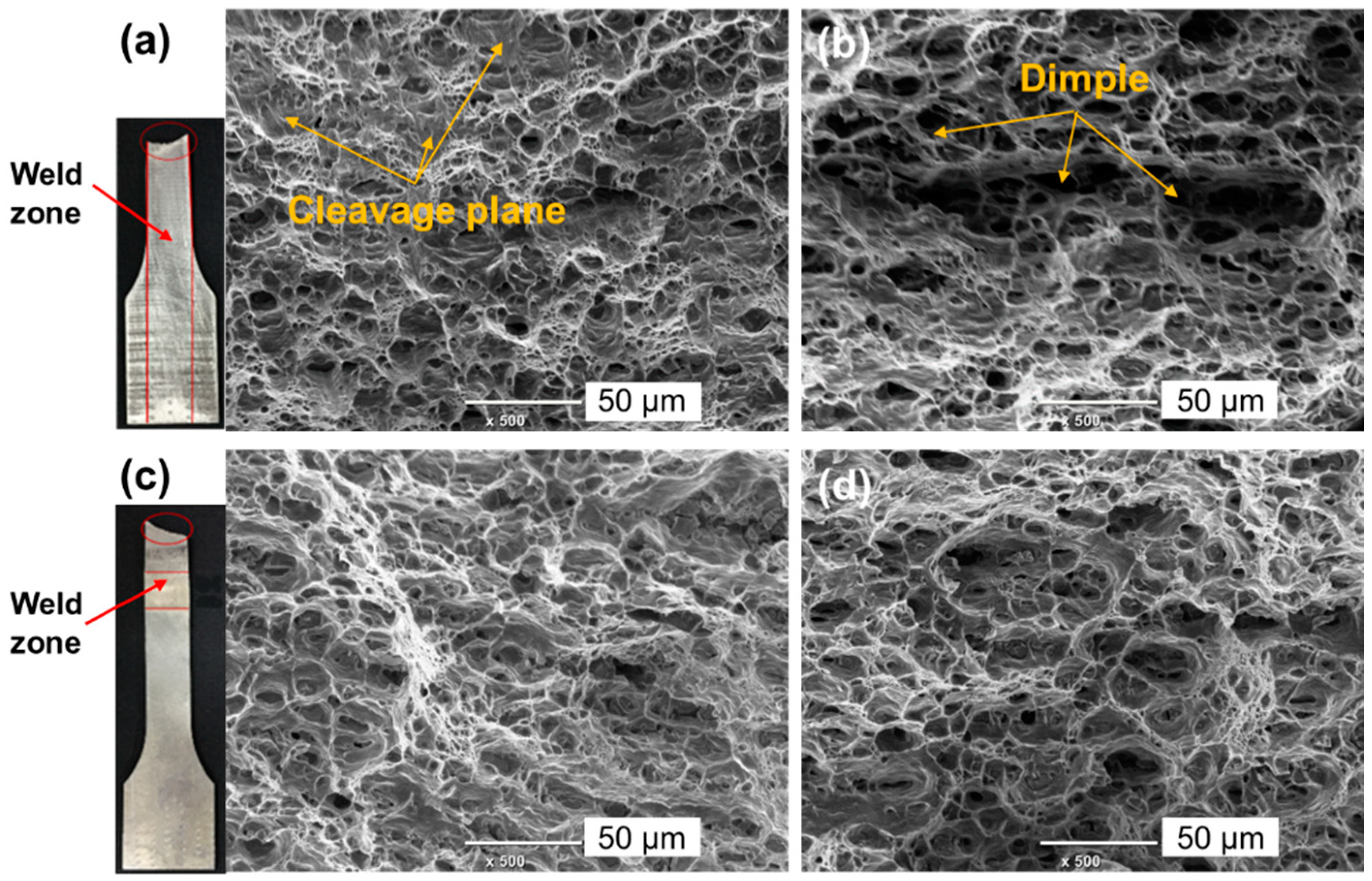
Figure 19a,b shows the tensile strength and elongation at different zones and directions. It can be found that the tensile strengths after deformation are all greater than the initial blank for all different zones and directions. Zhan et al. [25] have reported that significant work hardening and grain refinement will produce in the power spinning of aluminum alloy. Thus, the tensile strength is improved during power spinning. On the contrary, the elongation is greatly reduced for all samples after spinning deformation, as shown in Figure 19b. Especially, the elongation of WZ is much smaller than that of the BMZ. For the radial samples, the microstructure of the WZ and BMZ samples are totally different, which makes different deformation and fracture behavior for them. From Figure 20a and b, it can be seen that radial samples in the WZ and BMZ both present quantities of dimples, which means the ductile fracture type. However, many cleavage planes are also observed in the radial sample of the WZ (Figure 20a), which do not exist in the radial sample of BMZ (Figure 20b). Thus, the elongation of the radial sample in the WZ is much smaller than that in the BMZ. For circumferential elongation, the sample at the WZ is a mixture of weld joint material and base material and the weld joint locates the middle of the sample, as shown in Figure 18. Due to the lower deformation resistance of the base material than the weld joint, the sample will neck and fracture at the zone of the base material, as shown in Figure 20c. Thus, the circumferential samples at WZ and BMZ both present ductile fracture with quantities of dimples, as shown in Figure 20c,d. However, the inhomogeneous material property of the sample at the WZ will aggravate the inhomogeneous deformation and accelerate the occurrence of necking. As a result, it presents a lower elongation than the circumferential sample in the BMZ. From the above analysis, it can be found that the plasticity at the WZ is a “weak link” in spinning with TWB, which needs more concern in the practical application.
4. Conclusions
In this paper, the deformation, microstructure, and properties of the power spun aluminum alloy curved head with tailor welded blank (TWB) were investigated by FE simulation and experiment. The following conclusions can be drawn:
(1) The deformation behavior of the weld nugget zone (WNZ), heat affected zone (HAZ), and base material zone (BMZ) of 2219 aluminum alloy TWB were evaluated and molded, respectively. On this base, the FE model for power spinning of the curved head with aluminum alloy TWB was developed. During FE modeling, an effective meshing scheme for TWB was proposed to get high simulation precision and efficiency at the same time.
(2) In the spinning of TWB, the equivalent stress and strain in the BMZ present annular distribution, which is very close to the spinning of the homogeneous blank. However, WZ has larger stress but smaller strain than the BMZ due to its larger deformation resistance. The spiral local loading path of the roller and inhomogeneous deformability of TWB result in an asymmetric V-shaped distribution of strain near WZ, i.e., the boundaries between the WZ and BMZ show the larger strain while the WZ center presents the smaller strain than BMZ.
(3) For forming quality in the spinning of TWB, the existence of the weld line plays a little effect on the thickness uniformity, but leads to non-uniform unfitability distribution, and worse roundness compared to the spinning of the homogeneous blank. Compared to the initial blank, the circumferential and radial tensile strength in WZ and BMZ are all improved, while their plasticity is reduced after power spinning.
Author Contributions
Conceptualization, P.G.; Methodology, M.Z.; Formal analysis, P.G.; Investigation, F.M. and P.G.; Writing—original draft preparation, F.M.; Writing—review and editing, F.M., P.G., P.M. and M.Z.; Supervision, P.G.; Figures, P.M.; Data collection, F.M. and P.M.; Literature search, M.Z.
Funding
This research received no external funding.
Acknowledgments
The authors would acknowledge the funding support from the National Science Fund for Distinguished Young Scholars of China (No. 51625505) and the Key Program Project of the Joint Fund of Astronomy and National Natural Science Foundation of China (No. U1537203), National Natural Science Foundation of China (No. 51875467), Young Elite Scientists Sponsorship Program by CAST (No. 2018QNRC001), and the Research Fund of the State Key Laboratory of Solidification Processing (NPU), China (Grant No. 2019-TS-10).
Conflicts of Interest
The authors declare that there is no conflict of interest. The funders had no role in the design of the study; in the collection, analyses or interpretation of data; in the writing of the manuscript, or in the decision to publish the results.
References
- Xia, Q.X.; Xiao, G.F.; Long, H.; Cheng, X.Q.; Sheng, X.F. A review of process advancement of novel metal spinning. Int. J. Mach. Tools Manuf. 2014, 85, 100–121. [Google Scholar] [CrossRef]
- Music, O.; Allwood, J.M.; Kawai, K. A review of the mechanics of metal spinning. J. Mater. Process. Technol. 2010, 210, 3–23. [Google Scholar] [CrossRef]
- Threadgill, P.L.; Leonard, A.J.; Shercliff, H.R.; Withers, P.J. Friction stir welding of aluminium alloys. Int. Mater. Rev. 2013, 54, 49–93. [Google Scholar] [CrossRef]
- Xu, W.F.; Liu, J.H.; Luan, G.H.; Dong, C.L. Microstructure and mechanical properties of friction stir welded joints in 2219-T6 aluminum alloy. Mater. Des. 2009, 30, 3460–3467. [Google Scholar] [CrossRef]
- Zhang, Z.; Xiao, B.L.; Ma, Z.Y. Effect of welding parameters on microstructure and mechanical properties of friction stir welded 2219Al-T6 joints. J. Mater. Sci. 2012, 47, 4075–4086. [Google Scholar] [CrossRef]
- Mishra, R.S.; De, P.S.; Kumar, N. Friction Stir Welding and Processing: Science and Engineering; Springer: Berlin/Heidelberg, Germany, 2014. [Google Scholar]
- Kosturek, R.; Sniezek, L.; Wachowski, M.; Torzewski, J. The influence of post-weld heat treatment on the microstructure and fatigue properties of Sc-modified AA2519 friction stir-welded joint. Materials 2019, 12, 583. [Google Scholar] [CrossRef] [Green Version]
- Gao, P.F.; Fu, M.W.; Zhan, M.; Lei, Z.N.; Li, Y.X. Deformation behavior and microstructure evolution of titanium alloys with lamellar microstructure in hot working process: A review. J. Mater. Sci. Technol. 2019. [Google Scholar] [CrossRef]
- Gao, P.F.; Qin, G.; Wang, X.X.; Li, Y.X.; Zhan, M.; Li, G.J.; Li, J.S. Dependence of mechanical properties on the microstructural parameters of TA15 titanium alloy with tri-modal microstructure. Mater. Sci. Eng. A 2019, 739, 203–213. [Google Scholar] [CrossRef]
- Zhang, J.H.; Zhan, M.; Yang, H.; Jiang, Z.Q.; Han, D. 3D-FE modeling for power spinning of large ellipsoidal heads with variable thicknesses. Comput. Mater. Sci. 2012, 53, 303–313. [Google Scholar] [CrossRef]
- Zhan, M.; Yang, H.; Zhang, J.H.; Xu, Y.L.; Ma, F. Research on variation of stress and strain field and wall thickness during cone spinning. Mater. Sci. Forum 2006, 532, 149–152. [Google Scholar] [CrossRef]
- Zhan, M.; Yang, H.; Zhang, J.H.; Xu, Y.L.; Ma, F. 3D FEM analysis of influence of roller feed rate on forming force and quality of cone spinning. J. Mater. Process. Technol. 2007, 187, 486–491. [Google Scholar] [CrossRef]
- Zhang, Y.Q.; Xu, W.C.; Shan, D.B. Study on the spinning process of thin-walled aluminum alloy vessel head. Forg. Stamp. Technol. China 2006, 3, 74–78. [Google Scholar]
- Gan, T.; Yu, Z.Q.; Zhao, Y.X.; Evsyukov, S.A.; Lai, X.M. Effects of backward path parameters on formability in conventional spinning of aluminum hemispherical parts. Trans. Nonferr. Metal. Soc. 2018, 28, 328–339. [Google Scholar] [CrossRef]
- Heo, Y.M.; Wang, S.H.; Kim, H.Y.; Seo, D.G. The effect of the drawbead dimensions on the weld-line movements in the deep drawing of tailor welded blanks. J. Mater. Process. Technol. 2001, 113, 686–691. [Google Scholar] [CrossRef]
- Liu, J.; Gao, G.X.; Fakir, O.E.; Wang, L.L.; Lin, J.G. Hot stamping of AA6082 tailor welded blanks: Experiment and FE simulation. Manuf. Rev. 2016, 3, 8. [Google Scholar] [CrossRef] [Green Version]
- Wang, A.L.; Liu, J.; Gao, H.X.; Wang, L.L.; Masen, M. Hot stamping of AA6082 tailor welded blanks: Experiments and knowledge-based cloud–finite element (KBC-FE) simulation. J. Mater. Process. Technol. 2017, 250, 228–238. [Google Scholar] [CrossRef]
- Lee, W.; Chung, K.H.; Kim, D.Y.; Kim, J.; Kim, C.M.; Okamoto, K.; Wagoner, R.H.; Chung, K. Experimental and numerical study on formability of friction stir welded TWB sheets based on hemispherical dome stretch tests. Int. J. Plast. 2009, 25, 1626–1654. [Google Scholar] [CrossRef]
- Habibi, M.; Hashemi, R.; Tafti, F.M.; Assempour, A. Experimental investigation of mechanical properties, formability and forming limit diagrams for tailor-welded blanks produced by friction stir welding. J. Manuf. Process. 2018, 31, 310–323. [Google Scholar] [CrossRef]
- Ren, N.; Zhan, M.; Yang, H.; Zhang, Z.Y.; Qin, Y.T.; Jiang, H.M.; Diao, K.S.; Chen, X.P. Constraining effects of weld and heat-affected zone on deformation behaviors of welded tubes in numerical control bending process. J. Mater. Process. Technol. 2012, 212, 1106–1115. [Google Scholar] [CrossRef]
- Mennecart, T.; Güner, A.; Khalifa, N.B.; Tekkaya, A.E. Effects of Weld zone in Deep Drawing of Tailor Welded Blanks of High Strength Steels. Key Eng. Mater. 2014, 611, 955–962. [Google Scholar] [CrossRef]
- Ren, N. Study on Deformation Compatibility and Bending Limit in Steel Welded Tube NC Bending Processes. Ph.D. Thesis, Northwestern Polytechnical University, Xi’an, China, 2013. [Google Scholar]
- Xing, L.; Zhan, M.; Gao, P.F.; Ma, F. A method for establishing a continuous constitutive model of welded metals. Mater. Sci. Eng. A 2018, 718, 228–240. [Google Scholar] [CrossRef]
- Zhang, J.H. Deformation Laws of Power Spinning of D406A Large Ellipsoidal Heads with Variable Thicknesses. Ph.D. Thesis, Northwestern Polytechnical University, Xi’an, China, 2012. [Google Scholar]
- Zhan, M.; Wang, X.X.; Long, H. Mechanism of grain refinement of aluminum alloy in shear spinning under different deviation ratios. Mater. Des. 2016, 108, 207–216. [Google Scholar] [CrossRef]
Figure 1.
Determination of the material parameters in the weld zone (WZ): (a) flow chart; (b) sub-region division.
Figure 1.
Determination of the material parameters in the weld zone (WZ): (a) flow chart; (b) sub-region division.

Figure 2.
Stress-strain curves of different regions in TWB.

Figure 3.
Schematic of the target curved head component. Unit: mm.

Figure 4.
Schematic of the finite element (FE) model and regional division of the TWB.

Figure 5.
The schematic of the meshing method for TWB.

Figure 6.
The simulated circumferential distribution of equivalent strain near the WZ at the forming time of 21 s.
Figure 6.
The simulated circumferential distribution of equivalent strain near the WZ at the forming time of 21 s.

Figure 7.
Spinning formed components: (a) experimental result; (b) simulation result.

Figure 8.
Comparisons of forming results obtained by experiment and simulation: (a) profile of the component; (b) thickness distribution along generatrix in WZ; (c) thickness distribution near the WZ on a cross-section.
Figure 8.
Comparisons of forming results obtained by experiment and simulation: (a) profile of the component; (b) thickness distribution along generatrix in WZ; (c) thickness distribution near the WZ on a cross-section.

Figure 9.
Typical distributions of equivalent stress (a,c) and equivalent strain (b,d) at workpieces formed by welded blank and homogeneous blank during power spinning (t = 50 s).
Figure 9.
Typical distributions of equivalent stress (a,c) and equivalent strain (b,d) at workpieces formed by welded blank and homogeneous blank during power spinning (t = 50 s).

Figure 10.
Circumferential distribution of equivalent strain (a), thickness strain (b), circumferential strain (c), and radial strain (d) near WZ at a forming time of 50 s.
Figure 10.
Circumferential distribution of equivalent strain (a), thickness strain (b), circumferential strain (c), and radial strain (d) near WZ at a forming time of 50 s.


Figure 11.
Schematic of the deformation behavior (a) near WZ and vertical velocity distribution in the deformation region (b).
Figure 11.
Schematic of the deformation behavior (a) near WZ and vertical velocity distribution in the deformation region (b).


Figure 12.
Variation of deformation inhomogeneous degree during the spinning process.

Figure 13.
Variation of flange swing degree during the spinning process.

Figure 14.
Schematic of the analysis paths for the thickness and unfitability degree.

Figure 15.
Distribution of wall thickness along circumferential paths (a) and radial paths (b).

Figure 16.
Distribution of the unfitability degree along radial paths.

Figure 17.
Initial microstructure (a,c) and deformed microstructure (b,d) in the BMZ (a,b) and WZ (c,d).
Figure 17.
Initial microstructure (a,c) and deformed microstructure (b,d) in the BMZ (a,b) and WZ (c,d).

Figure 18.
Schematic of sampling location on the workpiece for tensile tests.

Figure 19.
Tensile test results at different conditions: (a) tensile strength; (b) elongation.

Figure 20.
Fracture morphology of the radial sample (a,b) and circumferential sample (c,d) in the WZ (a,c) and the base material zone (BMZ) (b,d).
Figure 20.
Fracture morphology of the radial sample (a,b) and circumferential sample (c,d) in the WZ (a,c) and the base material zone (BMZ) (b,d).


Table 1.
Mechanical properties of different regions in the tailor-welded blank (TWB).
| Mechanical Properties | BMZ | HAZ-L1 | HAZ-L2 | HAZ-L3 | WNZ | HAZ-R1 | HAZ-R2 | HAZ-R3 |
|---|---|---|---|---|---|---|---|---|
| Young’s modulus E (MPa) | 57,982 | 62,305 | 64,093 | 64,729 | 60,416 | 60,604 | 63,629 | 64,412 |
| Yield strength σs (MPa) | 88.35 | 74.67 | 83.01 | 86.39 | 67.59 | 73.09 | 80.66 | 84.78 |
| Microhardness (HV) | 48 | 55 | 53 | 50 | 67 | 58 | 54 | 52 |
Table 2.
Main processing parameters in the FE model and experiment.
| Parameters | Values |
|---|---|
| Mandrel speed nM (rpm) | 80 in arc segment and 60 in line segment |
| Feed rate f (mm/r) | 1 |
| Roller nose radius ρ (mm) | 4 |
| Roller diameter DR (mm) | 200 |
| Deviation rate | 0 |
| Roller oblique angle β (°) | 20 |
| Friction coefficient | 0.05 |
© 2019 by the authors. Licensee MDPI, Basel, Switzerland. This article is an open access article distributed under the terms and conditions of the Creative Commons Attribution (CC BY) license (http://creativecommons.org/licenses/by/4.0/).
Share and Cite
MDPI and ACS Style
Ma, F.; Gao, P.; Ma, P.; Zhan, M. Power Spinning of the Curved Head with Tailor Welded Aluminum Alloy Blank: Deformation, Microstructure, and Property. Metals 2019, 9, 1359. https://0-doi-org.brum.beds.ac.uk/10.3390/met9121359
AMA Style
Ma F, Gao P, Ma P, Zhan M. Power Spinning of the Curved Head with Tailor Welded Aluminum Alloy Blank: Deformation, Microstructure, and Property. Metals. 2019; 9(12):1359. https://0-doi-org.brum.beds.ac.uk/10.3390/met9121359
Chicago/Turabian StyleMa, Fei, Pengfei Gao, Pengyu Ma, and Mei Zhan. 2019. "Power Spinning of the Curved Head with Tailor Welded Aluminum Alloy Blank: Deformation, Microstructure, and Property" Metals 9, no. 12: 1359. https://0-doi-org.brum.beds.ac.uk/10.3390/met9121359
Note that from the first issue of 2016, this journal uses article numbers instead of page numbers. See further details here.