Laser Powder Bed Fusion of Stainless Steel Grades: A Review


1
Seamthesis Srl, Via IV Novembre 156, 29122 Piacenza, Italy
2
Dipartimento di Ingegneria, Università degli Studi di Perugia, Via G. Duranti 93, 06125 Perugia, Italy
*
Author to whom correspondence should be addressed.
Metals 2019, 9(7), 731; https://0-doi-org.brum.beds.ac.uk/10.3390/met9070731
Submission received: 11 May 2019
/
Revised: 24 June 2019
/
Accepted: 25 June 2019
/
Published: 28 June 2019
(This article belongs to the Special Issue Manufacturing and Application of Stainless Steels)
Abstract
:In this paper, the capability of laser powder bed fusion (L-PBF) systems to process stainless steel alloys is reviewed. Several classes of stainless steels are analyzed (i.e., austenitic, martensitic, precipitation hardening and duplex), showing the possibility of satisfactorily processing this class of materials and suggesting an enlargement of the list of alloys that can be manufactured, targeting different applications. In particular, it is reported that stainless steel alloys can be satisfactorily processed, and their mechanical performances allow them to be put into service. Porosities inside manufactured components are extremely low, and are comparable to conventionally processed materials. Mechanical performances are even higher than standard requirements. Micro surface roughness typical of the as-built material can act as a crack initiator, reducing the strength in both quasi-static and dynamic conditions.
1. Introduction
Additive manufacturing (AM), also known as 3D-printing, is an emerging technology [1], which is in the spotlight for its unique capability to produce near-net-shape components, even geometrically complex ones, without part-specific tooling being needed. AM is particularly suited for small batch production [2], weight reduction [3,4], part-customization [5,6], and functional integration [4,7,8,9], which is why it first emerged as a rapid prototyping technology. The adoption of AM technologies resulted in a new production paradigm [10,11]: the designer can project a component, or optimize the geometry of an already-existing one, according to its service conditions, and free from production-related constraints (e.g., undercuts, straight cuts, internal ducts with sharp edges). At the same time, AM made it possible to simplify component assembly, merging different parts into one single monolith. An emblematic example is the fuel nozzle shown in [12,13], which went from being an assembly of 20 parts to being a single unit. This allowed a 25% weight reduction.
A wider adoption of AM took place thanks to the possibility of processing metal alloys with mechanical properties that are comparable to the equivalent wrought alloys. Since 2000, AM technology has been assisting in a fast acceleration [14,15] due to the degree of development being gained in several sectors, i.e., lasers, computers, computer-aided design (CAD) technologies, programmable logic controllers (PLCs), and data storage systems [16,17]. The first commercially available AM system, back in 1987, was SLA-1 by 3D Systems, and it was based on the stereolithography technique (SLA stands for stereolithography apparatus): the desired piece is obtained through the superimposition of thin layers of ultraviolet light-sensitive liquid polymer solidified by an ultra-violet (UV)-laser source. Growing interest in the field led several companies and researchers to work simultaneously on developing systems for metal alloy handling. In this field, EOS Gmbh presented its first prototype (EOS M160) for metal processing in 1994, and the following year, the EOS M250 system was launched on the market [18]. In the meantime, Deckard filed a patent [19] concerning an apparatus capable of sintering powders thanks to a laser source. The cited manufacturing devices are the precursors of modern powder bed fusion (PBF) technology. PBF is a layer-wise production technology accomplishing material consolidation through a heat source, which can be a laser (in this case we refer to L-PBF) or an electron beam (EB-PBF): the spot of the heat source, impinging on the previously spread powder bed, releases the quantity of energy necessary to melt metal particles. Other AM technologies for metal alloys include: direct energy deposition (DED), binder jetting (BJ), sheet lamination (SL) and bound metal deposition (BMD). Besides the general AM advantages, the success of PBF (independently on the actual heat source) against other metal AM technologies, lies in its:
- capability of obtaining the best geometrical and dimensional tolerances;
- low waviness (the low-frequency roughness component) of surfaces, thus minimizing the need for machining allowance;
- capability of achieving the highest relative densities, up to 100%, with respect to wrought or forged metals;
- capability of producing both thin structures, e.g., lattice and trabecular, and heavy cross sections; and
- capability of minimizing oxide impurities, as it works under controlled atmospheres (usually nitrogen, or argon for reactive alloys).
The latter is extremely relevant for stainless steel alloys, as oxides could adversely affect their corrosion resistance and act as crack initiators [20,21]. Within the PBF subclass, L-PBF has gained much more interest due to its lower technological complexity and required production times [22], resulting in lower capital investment and production costs. Hence, the range of laser-based manufacturing systems is much wider than that of electron beam-based systems, and building envelopes have reached 1 m3, allowing for the production of larger components than EB-PBF. EB-PBF is to be preferred when processing high-cost crack-susceptible alloys (such as TiAl alloys), since residual stresses are suppressed and higher production costs are balanced by the higher added-value output. However, L-PBF processed materials can be affected by some process-related defects [23,24], including:
- high-levels of residual stresses, which can cause distortions, cracks and delamination;
- porosities and incomplete fusion-related defects;
- cracks (in susceptible alloys) and metastable microstructures, as a consequence of high cooling rates;
- balling phenomenon, at the origin of discontinuous scan tracks;
- micro roughness due to partially sintered metal particles, especially experienced on inclined surfaces.
In the following section, the causes of defects will be addressed, together with countermeasures. Focusing on metal alloys, it is, in principle, possible to manufacture every weldable metal alloy once the proper setting of working parameters is defined (e.g., laser power, layer thickness, gas fluxing). L-PBF techniques have been successful in producing functional components from a wide range of metal alloys [25], with working parameter identification and validation being the real know-how of L-PBF technology developers. Today, the most established and L-PBF verified alloys include: Aluminum alloys (AlSi10Mg, AlSi7Mg0.6), Cobalt alloys (CoCrMo), Nickel alloys (Haynes HX, Inconel 625, Inconel 718), Iron alloys (Maraging steels, AISI 304, AISI 3016L, Tool steels) and Titanium alloys (Ti6Al4V, Ti6Al4V ELI, CP-Titanium Grade 2).
Stainless steels are nowadays used in almost every application field. In fact, thanks to their peculiar combination of properties—namely, strength and corrosion resistance—since its discovery in the early 19th century [26], they have been adopted in automotive [27,28], construction and building [29,30,31], energy [32,33,34], aeronautical [35,36], medical [37] and food [38,39,40,41] applications. The implementation of stainless steel grades in L-PBF systems, together with a deeper understanding of the technology, could definitely result in a wide adoption of the technology itself. Currently, L-PBF is already being used for stainless steel component production in engineering applications, but a fundamental lack in standardization and proper metrology definition [42,43,44,45,46,47] is limiting the spread of technology: for this reason, international committees are joining together to accelerate the process [48,49]. The challenge is to consistently define proper processing routes and requirements, standard mechanical requirements, proper heat treatments, dynamic performances, post-processing and qualification needs. This review aims at reporting the state of the art of the application of stainless steel alloys in L-PBF systems; starting from the working conditions of the cited process (and their effect on process performance), a list of stainless steel grades already tested on L-PBF systems is shown, together with their relative density, microstructure, quasi-static tensile properties and fatigue performances. In conclusion, the not yet exploited potential of making stainless steel via L-PBF systems will be discussed, along with future challenges.
2. Laser Powder Bed Fusion Working Principles and Process-Related Defects
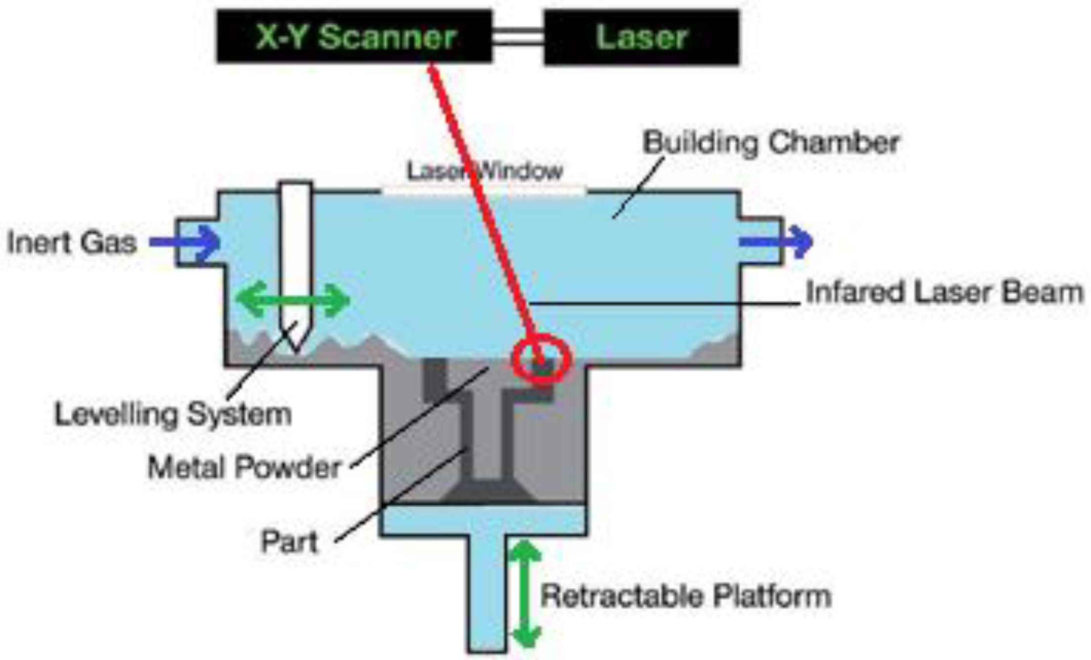
The melting and fusion of material in L-PBF is obtained in a discrete way: layer-by-layer, the laser melts new powder, which solidifies as soon as the laser moves on to the neighbouring powder portion, leading to a continuous solid. The final part is an ensemble of micron-size welding lines overlapping in the horizontal plane and superimposed in the vertical plane. A representation of L-PBF working principle is reported in Figure 1, and the overall process can be summarized as follows:
- CAD manipulation and model “slicing”, the latter being performed by specific software properly subdividing the geometry into n slices with a height equal to the selected layer;
- loading data to the L-PBF hardware;
- production stage:
- spreading the powder layer, thanks to a rake or roller (Levelling System in Figure 1);
- switching on the laser, for melting and subsequent solidification;
- lowering of the building platform, which is retractable;
- previous steps 3a–3c repeated until all layers are fused;
- removal of unused powder (“metal powder” in Figure 1) and extraction of the final part.
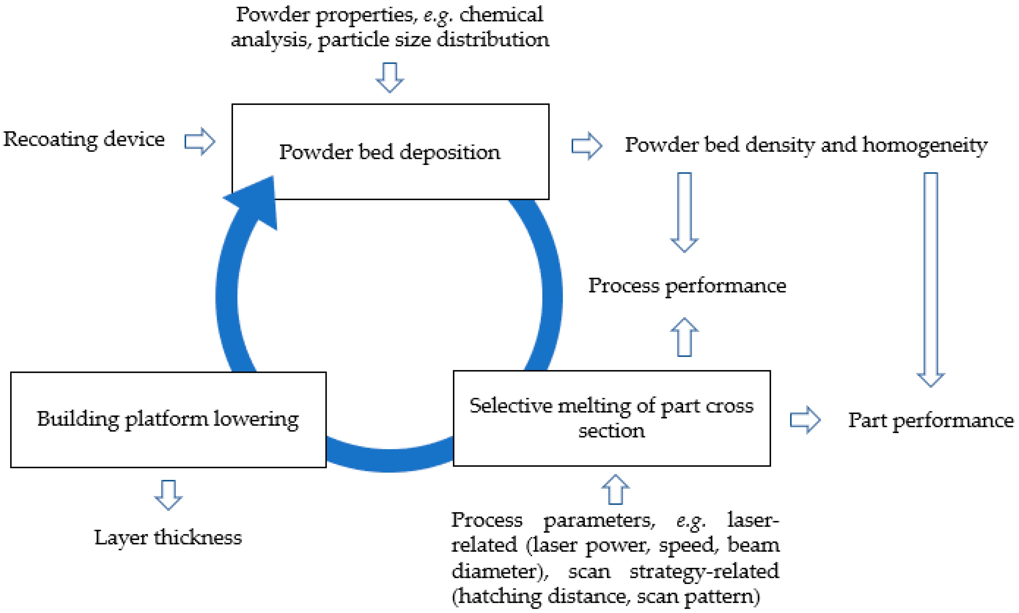
The peculiar nature of L-PBF involves the interaction at the micron-sized level between photons (generated by the laser source) and a discrete metal substrate (the powder bed), consisting of metal particles dispersed in an inert gas atmosphere. Complicated physics are involved, such as absorption, transmission and reflection of laser energy, adhesion of micron-scale particles, rapid melting and solidification, molten metal flow, metal evaporation and microstructural evolution [10,23,51,52,53,54,55,56,57]. L-PBF relevant parameters can be classified into two groups: some of them directly set by users (e.g., laser power and speed, scan pattern, layer thickness and powder properties), while others are process-related (e.g., powder bed density, powder bed temperature). The latter can be indirectly controlled, using the first set of parameters, but it is harder to address. Several research groups are working to develop physical models to describe, and consequently control, the process, with some examples being described in [58,59,60,61,62,63,64,65,66,67,68,69]. Developed models also aim at defect forecasting and mitigation [70,71,72,73,74,75]. It is of major relevance to remember that, unlike conventional processes, all AM technologies are producing the alloy and the specific geometry to be put in service simultaneously. This means that process parameters usually related to the material quality (e.g., laser parameters determining melting and solidification behavior) now directly affect the performance [76] of the final components, as shown in Figure 2. The result is that, even if some post processing is projected (e.g., heat treatments, machining), material-related defects arising during 3D printing will cause the artefacts to be discarded at the end of the whole cycle, which can take up to weeks of work for large components.
To obtain a fully dense material, it is necessary to understand the effect of various process parameters. L-PBF machinery typically installs a system of lenses and a scanning mirror—or galvanometer—to move the position of the laser beam spot on the powder bed. The laser spot is used like a pen tip that, while rastering the surface of the powder bed, solidifies the powdered metal, releasing the energy necessary to achieve complete melting. Some laser characteristics are listed in Table 1: properties are reported in ranges, as they can vary between different system providers or as an effect of specific metal alloys. Scanning strategy parameters are particularly relevant for the quality of the manufactured component as they affect the heat cycle experienced by the alloy, determining, for example, final microstructure, residual stresses [77], and other defects.
The most relevant parameters to scanning strategy are:
- laser power;
- laser speed;
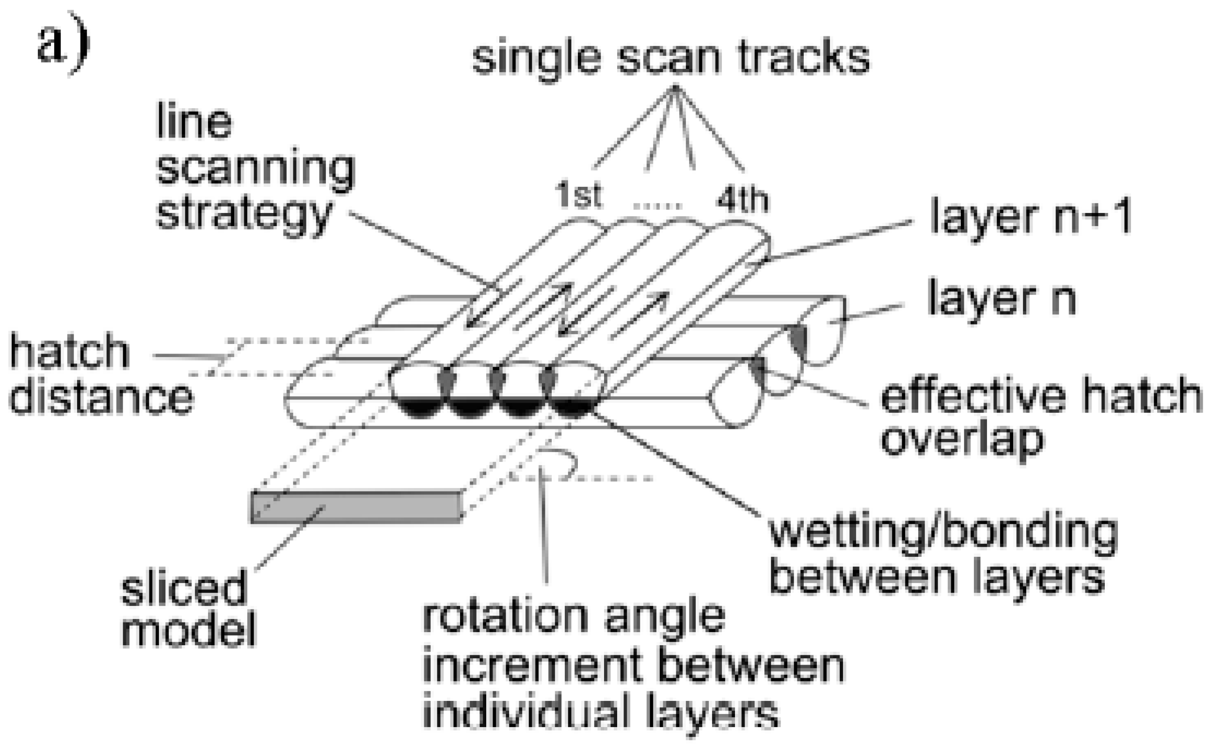
- hatch distance—the distance from the middle line of two consecutive lines, determining the effective hatch overlap, according to Figure 3;
- layer thickness;
- scan pattern.
A short list of L-PBF machinery properties and related manufactured components features are shown in Table 1.

Table 1.
L-PBF products and main properties.
| L-PBF Machinery Characteristics | |
|---|---|
| Heat source | One fiber laser, or more |
| Laser power [W] | 50–1000 |
| Laser speed [mm/s] | 10–15,000 |
| Laser beam diameter [µm] | 30–500. Most common, 80–100 |
| Building chamber atmosphere | Inert gas—Typically, Nitrogen or Argon |
| Building rate [cm3/h] | 2–120 |
| Building volume [mm] | Up to 800 × 400 × 500 (width × depth × height)—most common, 250 × 250 × 300 |
| Ref. | [2,10,79,80,81,82,83,84,85] |
| L-PBF Produced Components Features | |
| Relative density 1 [%] | Up to 100 |
| Upper surfaces roughness (Ra,X-Y) [µm] | 4–10 |
| Lateral surfaces roughness (Ra,Z) [µm] | >20 |
| Minimum feature size [µm] | 75–250 |
| Geometric tolerance [mm] | ±0.05–0.1 |
| Impurities | Risk of contamination by process gas (nitrogen) or moisture |
| Effect on chemical composition | Minimum loss of low vapor pressure alloying elements |
| Powder size requirements [µm] | 10–60 |
| Ref. | [10,51,79,86,87,88] |
1 Relative density is evaluated as a ratio between the density of L-PBF produced material and the density of the same metal alloy processed with conventional technologies (e.g., rolling, forging).
The combined effect of the listed parameters can be calculated through the heat input released by the laser source: it can be quantified by the energy density parameter E, according to Equation (1):
E = P/v·φ [J/mm2]
Where P is laser power (W), v is laser speed (mm/s) and φ is the laser beam diameter at the powder bed surface. In Table 1, typical values for the mentioned parameters are reported. An alternative formulation is given by Equation (2):
where h refers to the hatch distance, as pointed out in Figure 3, and t is the layer height.
E = P/v·h·t [J/mm3]
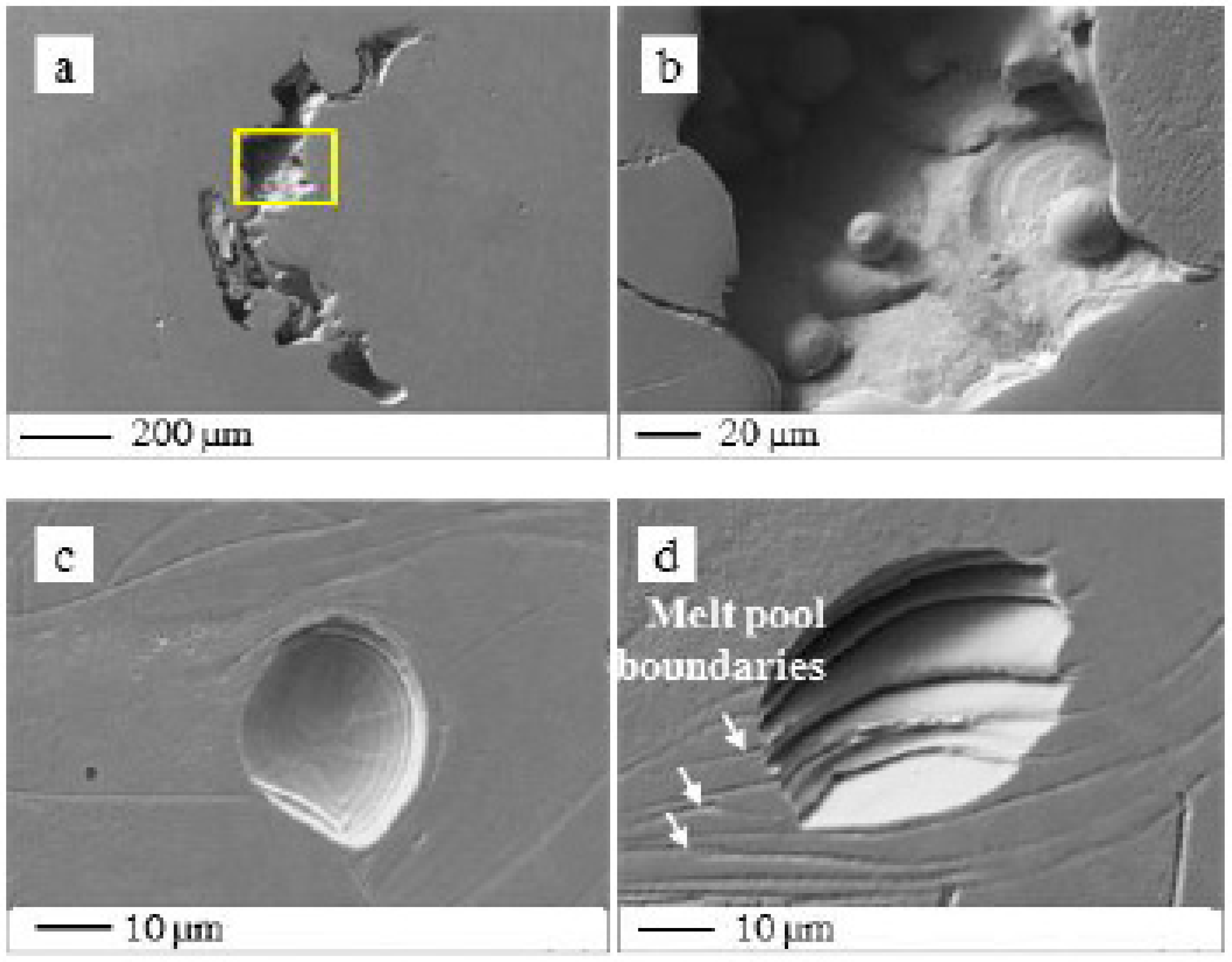
At a micro scale, it is important to set the proper parameters to guarantee the highest achievable density. In Figure 4, different kinds of porosities (detrimental for density) are shown:
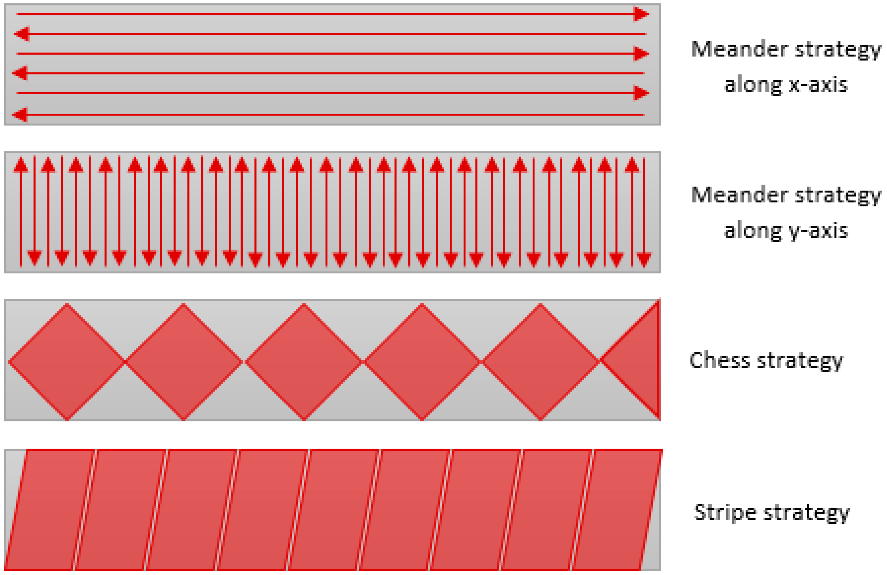
The temperature inside the laser spot usually reaches thousands of degrees Kelvin (or Celsius), and it is usually higher than the melting point of metal. The molten metal is strictly in contact with the substrate or the previously consolidated layers, determining a steep temperature gradient [10] that is at the basis of residual stresses phenomenon [91,92]. Scan pattern refers to the path followed by the laser beam in order to accomplish the complete melting of every slice or layer. At a macro level, the laser can raster the whole length of the slice in unidirectional or bidirectional mode, called the meander strategy in Figure 5 (consequent lines are scanned in the same direction or opposite), or it can subdivide the area in islands—also known as the chess strategy—or stripes (according to Figure 5). Furthermore, it handles a rotation angle between consequent layers, as can be seen in Figure 3, where the drawing represents a 90° rotation between the i-th and the i+1-th layer. The chess or stripe strategies and rotation angles are selected to reduce thermal gradients along the single layer (and, in turn, residual stresses [93]), while raising the level of anisotropy inside the material.
Residual stresses, together with porosities, are of major concern in L-PBF as they can determine the distortion of artefacts after cut or the failures of a production job, even at its final stage. To resolve the first problem, it is common practice to heat treat components still attached to the building platform; this helps in relaxing residual stresses before the removal. In the second case, it is necessary to reduce the temperature gradients experienced by the materials.
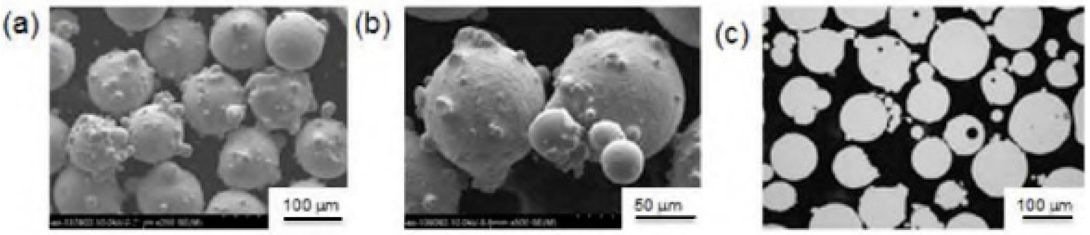
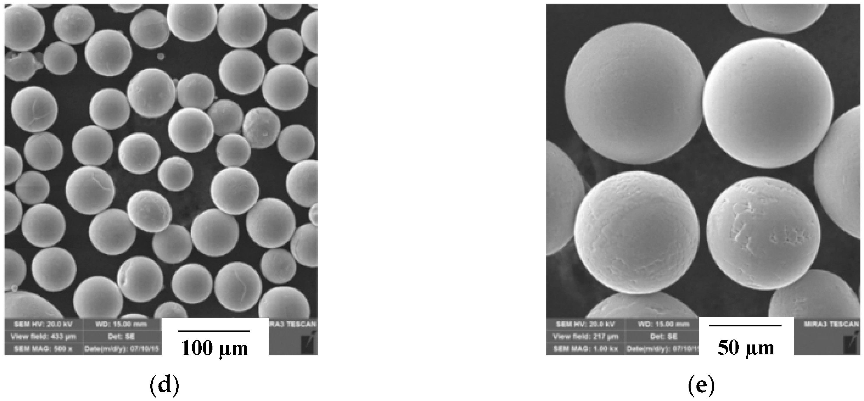
The laser interacts with a discrete substrate formed by metal powder particles that are used as feedstock; these are micron-sized particles of the selected alloy, obtained using specific processes. It is necessary for L-PBF to flow easily during the recoating phase to guarantee a proper powder bed density; various studies [94,95,96,97] demonstrated the impact of different particles characteristics on the quality (in particular, in terms of density and surface roughness) of the final component. The majority of metal powders used in L-PBF systems are, nowadays, produced through an atomizing process that involves the interaction of a stream of molten metal with a high energy jet, usually gaseous (e.g., nitrogen of argon) [98]; this process is called gas atomization (GA). Alternatively, it is possible to use plasma atomized (PA) powders, produced using plasma torches instead of the gas stream. In Figure 6, the main differences are appreciable: GA particles are characterized by the presence of satellites (small particles attached to the surface of bigger ones) and sometimes they show gas pores (Figure 6c), PA powder is mostly spherical, with smooth surfaces and a narrower Particle Size Distribution (PSD).
To summarize the effect of the cited process aspects:
- laser energy density E directly impacts melting behavior: at low scan speed and high laser power, E is high, causing evaporation, porosities and potential denudation of near surfaces, while high scan speed and low power determine low E density, which is insufficient to fully melt a proper powder volume and interlayer bonding [23,101];
- increasing the layer thickness, keeping the other parameters unmodified, can result in residual stresses mitigation [102], and a more economical process (i.e., with reduced production times), but it is necessary to evaluate the potential lack-of-fusion defects;
- the effect of laser power on melt pool defects and residual stresses is greater than that of laser speed [104];
- moreover, surface roughness is affected by the width of the melting track, which in turn is controlled by laser power and scan speed values. Inclined surfaces are the most disadvantaged, because heat conduction in the powder bed below is less efficient than the areas over the consolidated material [107];
- porosities must be carefully controlled, as they are detrimental for fatigue resistance of alloys; in particular, pore size has been demonstrated to be the most relevant parameter [108].
Considering the previously described aspects, it seems evident that parameter selection is the result of modelling and experimental validation aiming at reducing production time and costs while guaranteeing the melting of a proper quantity of metal (both powdered and consolidated). One challenge is that the best set of parameters (even if validated) is no longer valid as soon as you change the laser you are working with (i.e., when using a different manufacturing machine), the powder batch (e.g., in terms of chemical analysis, particle size distribution, powder morphology) [109], or the geometry (e.g., sharp features, heavy sections or portion of inclined surfaces facing loose powder). A lot of work has been performed in order to investigate the optimal working conditions of L-PBF and guidelines for the selections of parameters [110,111,112,113,114,115,116].
3. Stainless Steel Grades Processed in L-PBF Systems
Stainless steels are widely employed for their unique performances at room and high temperatures, owing to their chemical and microstructural features. In L-PBF, the right chemical composition is guaranteed by wise manipulation and correct storage of metal powders, mainly to avoid oxygen, moisture or oil pick up [117]; meanwhile, the microstructural properties (e.g., grain size, phases) are determined by the processing parameters. Specifically, the final microstructure depends on the local heat flow direction, competitive growth of grains, and laser scanning strategy. Typical cooling rates are in the range 105–106 K/s [10,118,119] due to the heat exchange with the gas atmosphere, the unfused powder, and the material already consolidated underneath; the resulting solidification microstructure is fine and far from that provided by thermodynamic equilibrium [120]. The laser scanning strategy has an impact on texture; for example, when the scanning strategy is set with no rotation between subsequent layers, the as-built material exhibits a fibrous aspect with a <001> direction of grain growth (building direction, z, normal to the building platform). This situation leads to a strongly orthotropic behavior of the material [81]. On the other hand, selectively scanning the powder bed in small islands, sometimes non-consecutively, and rotating the direction of the laser between the different layers, makes it possible to obtain an almost untextured microstructure. An elongated grain structure along the z-direction (as shown in Figure 8), is due to both prevalent heat extraction from the bottom side of the melt pool (i.e., the building substrate) and epitaxial grain growth, like fusion welding. In L-PBF, the existing base-metal grains (i.e., the grains existing in the last melted layer) act as a substrate for nucleation [53]. Moreover, the melting of subsequent layers causes a reheating of the already consolidated material, determining the solid-state phase transformations.
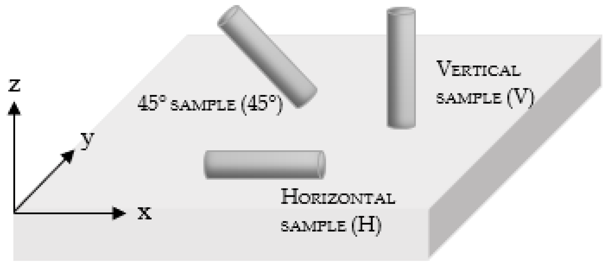
The peculiar microstructure arising from the described physical phenomena determines the different mechanical performances depending on the tested direction, or, in the case of the final components, on the service loading condition. This is the why the best course of action, as a rule, is to produce tensile specimens with their main axis oriented along different directions, as schematized in Figure 8; vertical specimens (V) are representative of the commonly identified longitudinal direction, while horizontal specimens (H) are representative of the transversal direction. The described unique metallurgical behavior of materials produced via AM led Murr et al. [121] to affirm that such a methodology could extend traditional materials science and engineering as far as making it possible to plan application-specific microstructural architectures in as-built components.
In the following sections, a review of mechanical performances obtained from L-PBF processed alloys is reported. For ease of reading, the correlated process parameters are not shown, but can be consulted in referenced papers. The authors would like to underline that tensile results reported under the as-built conditions in Table 2 and Tables 4–6 involved testing samples with no stress-relieving heat treatment; the presence of residual stresses inside the specimen can result in deformation (if not properly machined) and yield strength values affected by the presence of a tension status of compression or tension inside the material itself, even before load is applied. This observation should aid readers in understanding the primary importance of stress-relief in L-PBF.
3.1. Austenitic Stainless Steel Grades
Austenitic stainless steels commonly processed in L-PBF systems are essentially alloy 304, alloy 304L and AISI 316L, the latter being the only one of these to have been commercialized by systems manufacturers [122,123,124,125,126].
- In Table 2, tensile results are reported and compared to the standard minimum requirements:
- tension tests performed at room temperature showed good performance, apart from fracture elongation, with results being higher than the minimum requirements usually applied for the selected stainless steel grades processed with conventional technologies;
- fracture elongation is the most negatively affected parameter, for samples tested under the as-built conditions;
- analyzing the listed tensile properties for 316L stainless steel powders, we can state that the experimental research performed in the cited papers achieved comparable results. It can be assumed that they all used proper parameter sets.
Table 2.
Tensile strength of austenitic stainless steel grades obtained from L-PBF, compared to standard reference values.
Table 2.
Tensile strength of austenitic stainless steel grades obtained from L-PBF, compared to standard reference values.
| Grade | Equipment | Relative Density [%] | Cond. | BD | Test Cond. | YS [MPa] | UTS [MPa] | El. [%] | Ref. |
|---|---|---|---|---|---|---|---|---|---|
| 304 | SD | NR | As built | H | RT | 530 | 700 | 38 | [105] |
| 45° | 370 | 540 | 29 | ||||||
| V | 450 | 550 | 58 | ||||||
| 304L | 3D Systems ProX-300 | 99.99 | As built | - | RT | 485 | 712 | 61 | [127] |
| 316L | SLM Solutions 125HL | 95.99–99.30 | HT–1040 °C/4h | V | RT | 376 | 637 | 32.4 | [128] |
| 316L | As built | H | RT | 528 | 639 | 38.0 | [78] | ||
| SLM Solutions 280HL | >99 | 45° | 590 | 699 | 34.1 | ||||
| V | 439 | 512 | 11.8 | ||||||
| 316L | Sisma MYSINT100 | 99.3–100 | As built | 45° | RT | 505–515 | 650 | 41 | [89] |
| V | 430–495 | 550-575 | 66–72 | ||||||
| 316L | Renishaw AM250 | NR | As built | H | RT | 554 | 685 | 36 | [129] |
| 316L | NR | NR | As built | - | RT | 456 | 703 | 45 | [118] |
| - | 250 °C | 376 | 461 | 31 | |||||
| - | 1100 °C | - | 300 | 15–18 | |||||
| - | 1200 °C | - | 150 | 20 | |||||
| Standard Reference Values | |||||||||
| Grade | Condition | Test condition | YS [MPa] | UTS [MPa] | El. [%] | Ref. | |||
| 304 | Annealed–hot finished | RT | 205 | 515 | 40 | [130] | |||
| 304L, 316L | Annealed–hot finished | RT | 170 | 485 | 40 | ||||
Cond.—Condition; BD—Building Direction; YS—Yield Strength; UTS—Ultimate Tensile Strength; El.—Elongation; SD—Self-developed; NR—Non reported; RT—Room Temperature; HT—Heat-treated; H—Horizontal; V—Vertical.
Table 3 contains some fatigue resistance results, revealing the beneficial effect of machining operations, in particular on high cycle fatigue (which is more sensitive to surface conditions and eventual crack presence). Low cycle fatigue [131] showed little effect from reducing surface roughness.
Microstructural characterization performed by [127,134,135] on both 304 and 316L stainless steels showed common features:
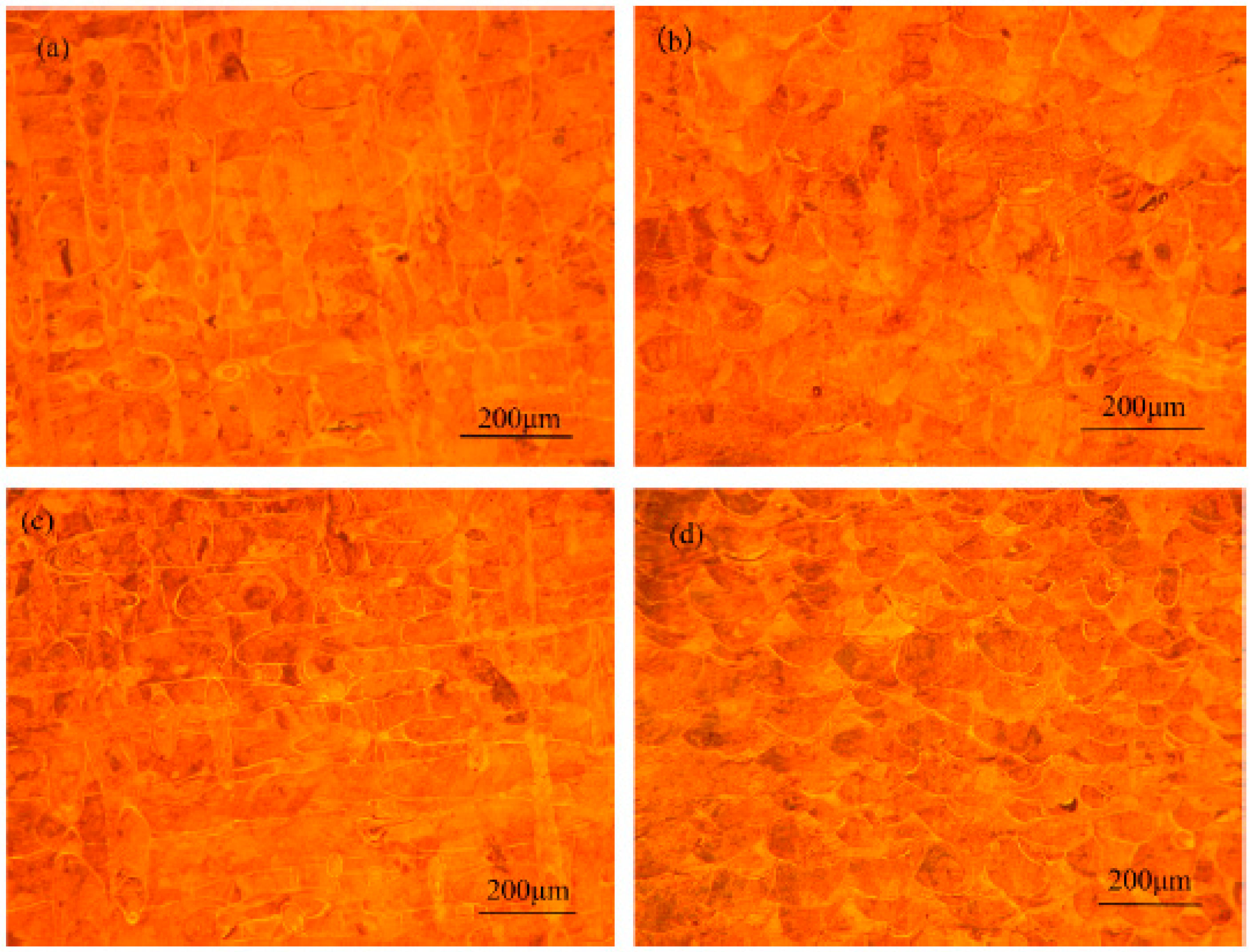
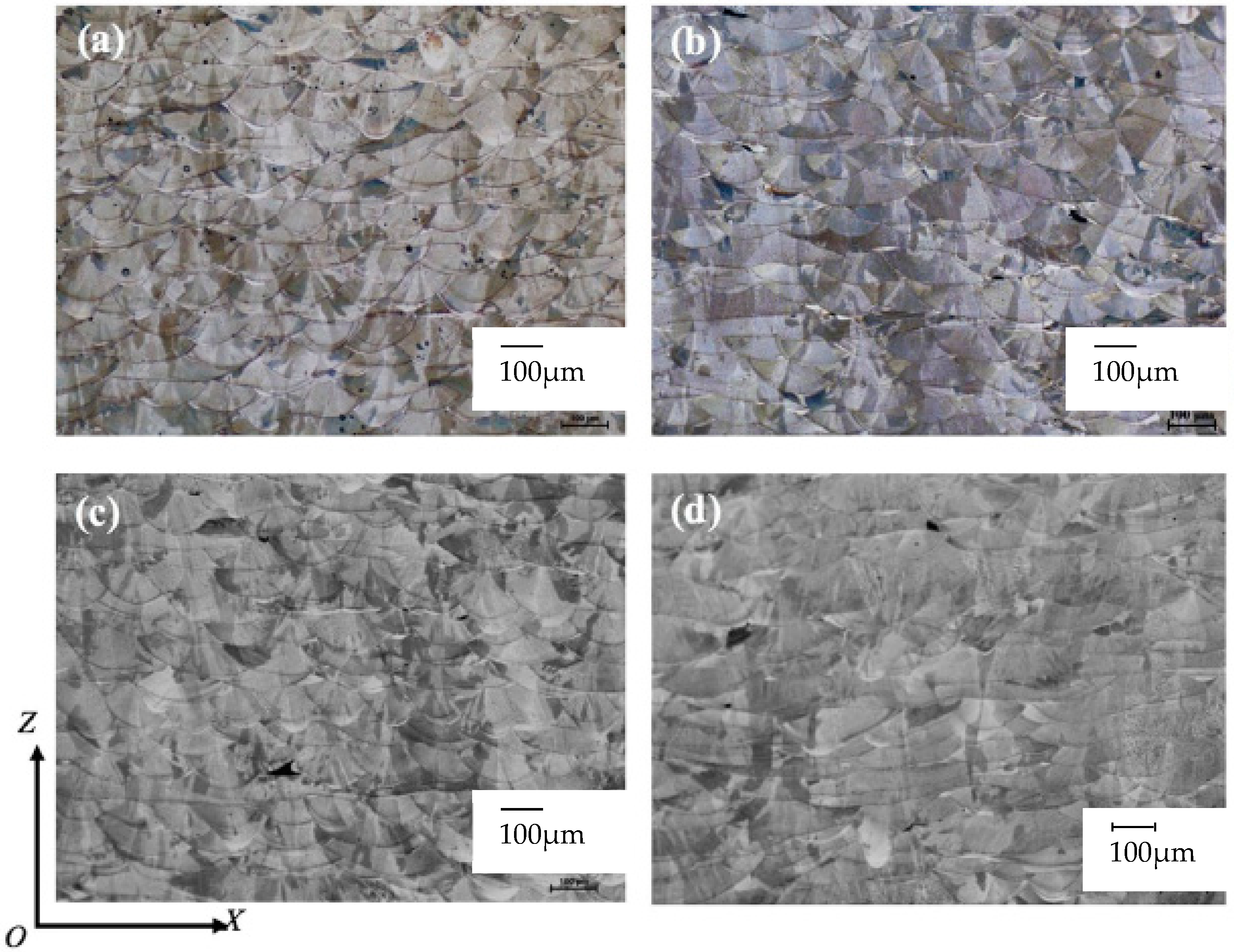
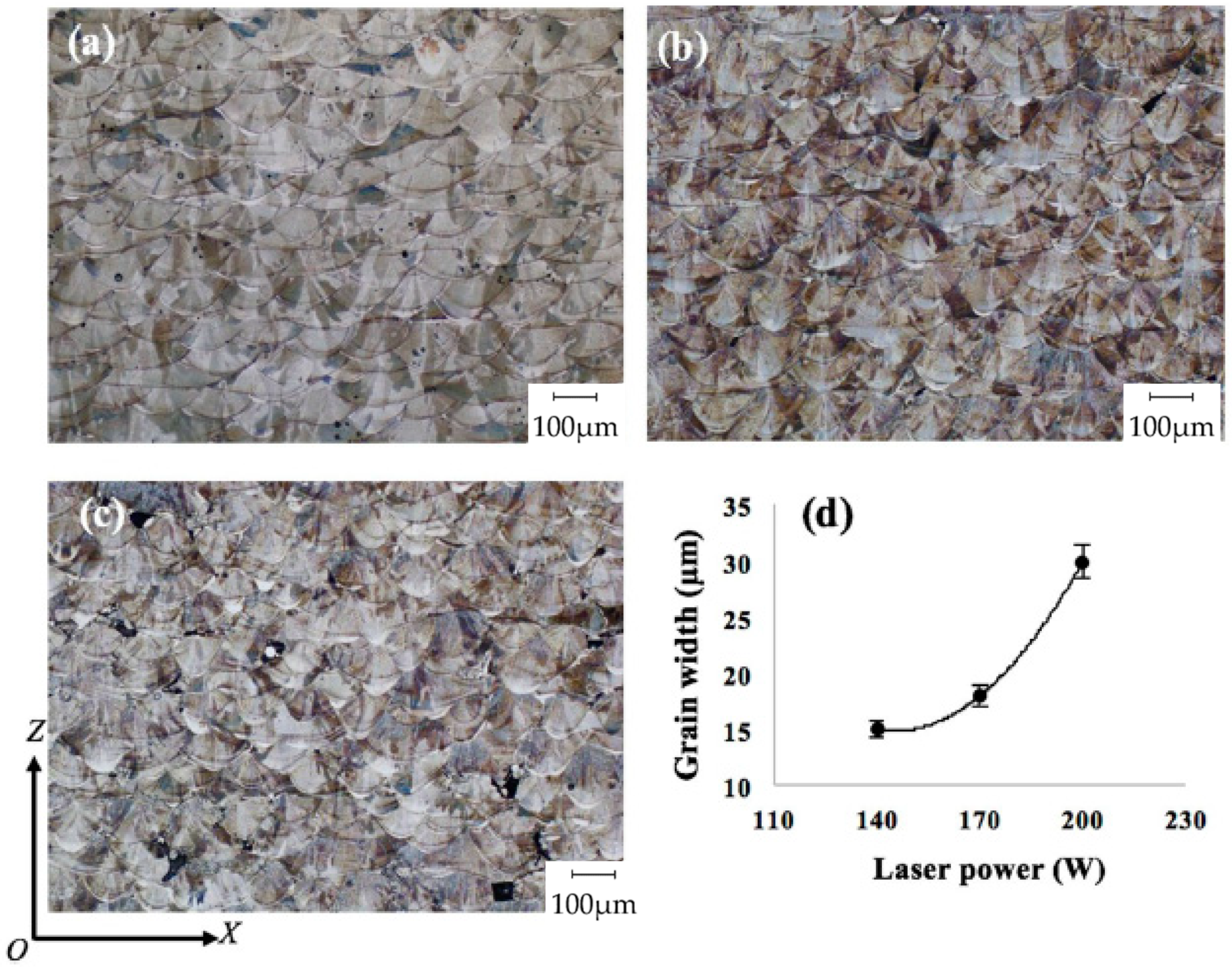
- grain size is basically independent of the selected scanning strategy, as long as the laser power is kept constant (see Figure 9);
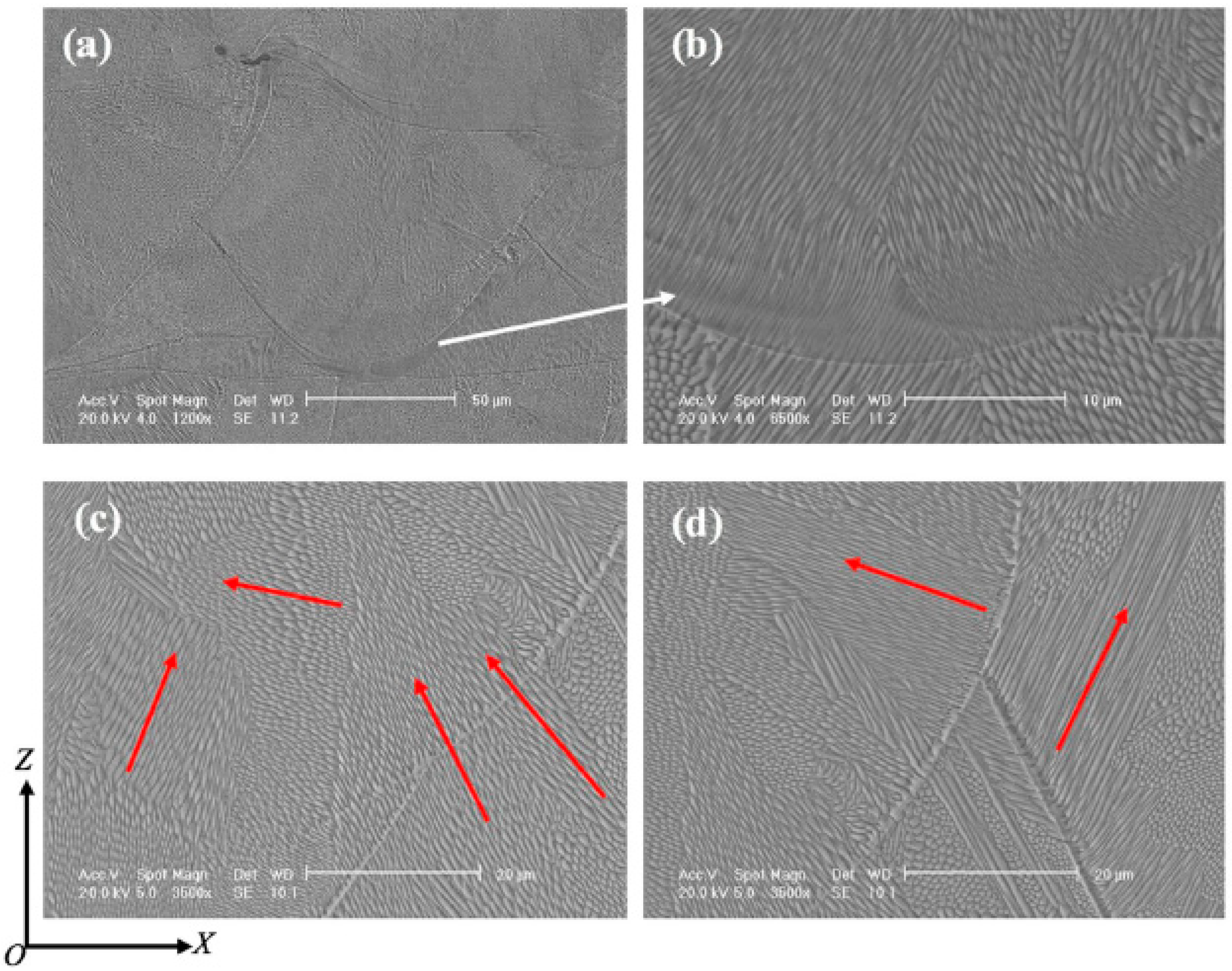
- as-built grains are characterized by needle-like structures with medium sizes of 500–800 nm and a high aspect ratio, oriented along different directions even in a single weld bead (see different growing orientations marked by red arrows in Figure 12);
- two types of boundaries were observed by [135]: cell boundaries (formed by dislocations) and colony boundaries (prior high-angle austenite grain boundaries);
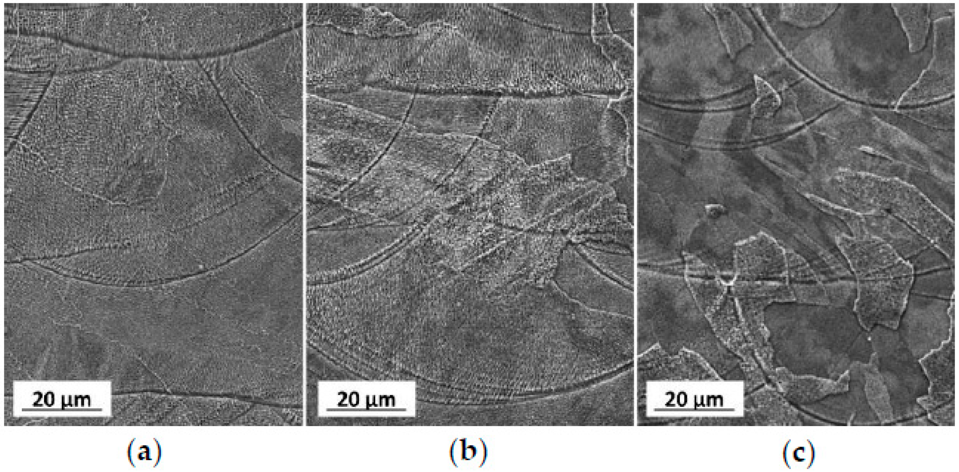
- in Figure 13, it can be seen how annealing heat treatment affects the starting microstructure (in Figure 13a): cell boundaries were unchanged after heat treatment at 800 °C, but they were not present after heat treatment at 900 °C. In contrast, colony boundaries were unmodified, meaning that no recrystallization phenomena had taken place.
3.2. Precipitation Hardening Stainless Steel Grades
After austenitic grades, precipitation hardening stainless steels, and 15-5 PH and 17-4 PH alloys, particularly (mostly applied for aeronautic and oil and gas parts production), are the most widespread and characterized grades of L-PBF equipment.
Auguste et al., in [136], and Murr et al., in [137], both worked on L-PBF 17-4 PH stainless steel, studying the effects of different powder batches on the final microstructure; in [136], the main difference was the Niobium content of the feedstock, while [137] investigated the effect of powder processing atmosphere and working inert gas.
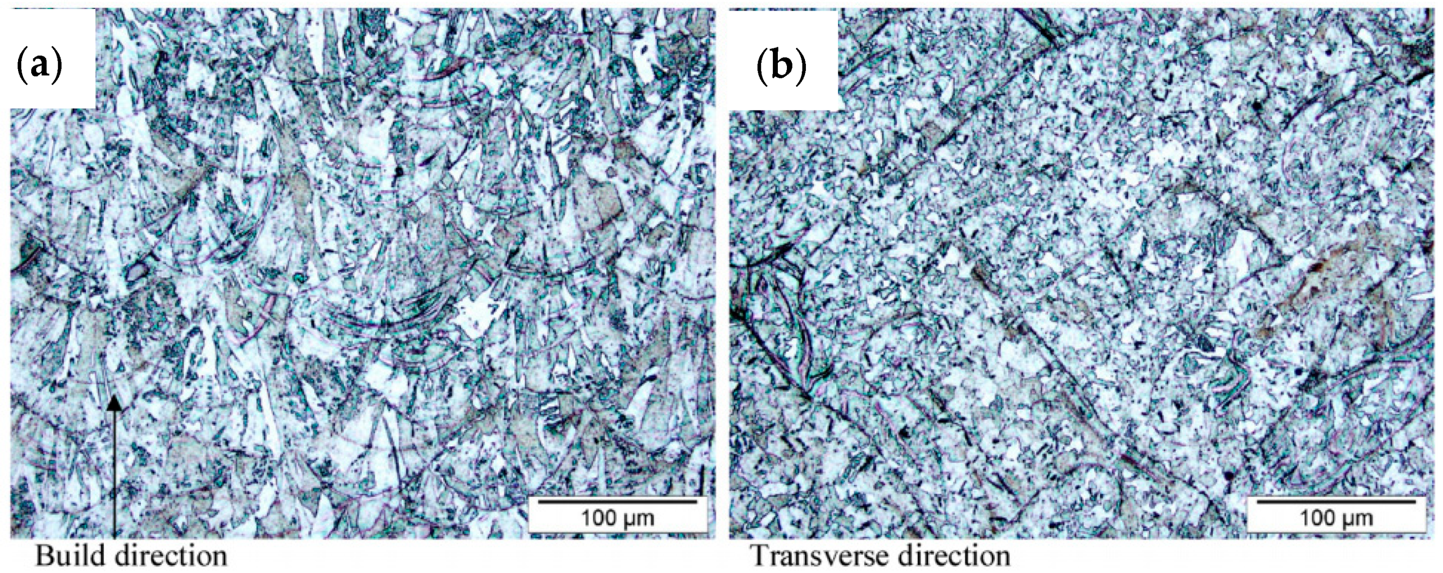
- 17-4 PH samples showed columnar grains oriented along the building direction, clearly visible in the samples in Figure 14a, Figure 15 and Figure 16. These observations are in accordance with those performed on austenitic stainless steels in the previous Section 3.1;
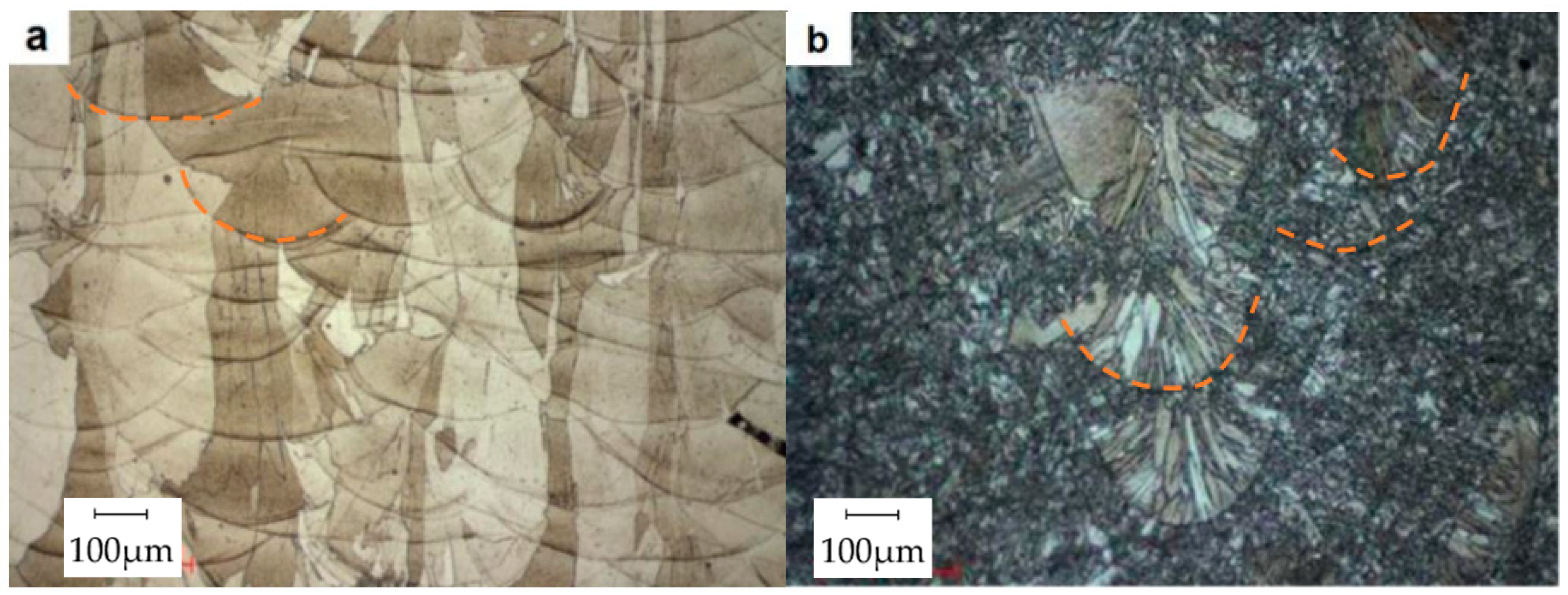
- As-built niobium-rich material, shown in Figure 14a, features mainly ferritic grains, with a minor content of martensite and residual austenite. Ferritic grains are characterized by a high aspect ratio, and the largest dimension reaches hundreds of micrometers. Ferritic microstructure is in contrast to the typical martensitic microstructure observed in this alloy;
- On the other hand, the as-built material shown in Figure 14b shows an overall martensitic microstructure, with a grain size in the range of 1–20 µm;
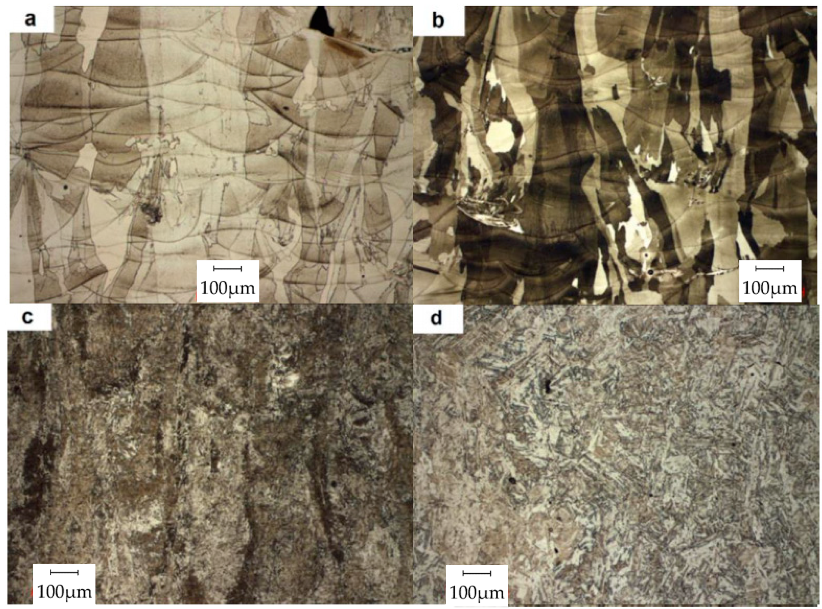
- Ferrite-rich samples do not show microstructural evolution after tempering at 480 °C (Figure 15a) and 550 °C (Figure 15b) with respect to Figure 14a. Martensitic microstructure and desired mechanical properties were achieved only after full material homogenization (Figure 15d and Table 3). This observation is in line with the thermal stability already underlined in austenitic 316L samples;
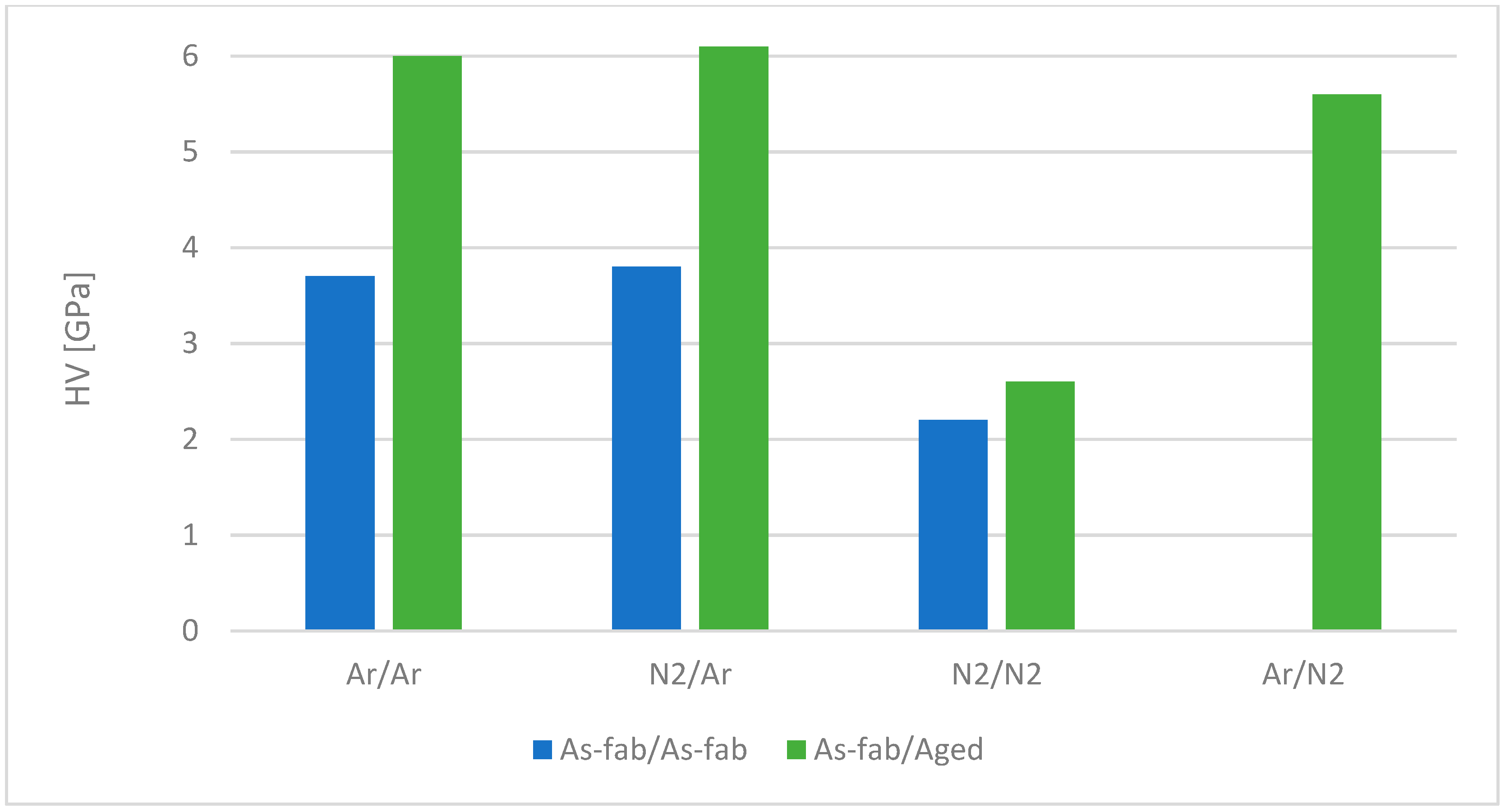
- Ar-atomized and N2-atomized powders produced completely martensitic phase materials when fabricated in an Ar environment (Figure 16 refers to a sample obtained from Ar-processed powders in Ar L-PBF atmosphere). Conversely, Ar-atomized powder and N2-atomized powder showed different behavior after N2 L-PBF processing gas environment; Ar-atomized powders fused in N2 produced fully martensitic components, while the N2-atomized powder fabricated in a N2-gas environment produced austenitic components containing roughly 15% martensite (Figure 17);
- Different microstructural observations obtained comparing Figure 16 and Figure 17 were confirmed by hardness measurements, with the results being reported in Figure 18; the austenitic sample hardness is lower than the martensitic one, and little variation can be appreciated after aging treatment, in contrast to the martensitic one, which underwent second-phase precipitation.
The tensile performances exhibited by L-PBF 17-4 PH specimens, summarized in Table 4, are characterized by a wide dispersion between different referenced works. In particular, the as-built alloy does not reach minimum standard requirements, resulting in the need to apply (and, eventually, develop) specifically tailored heat treatments. Yadollahi et al. [138] underlined the need for heat treating L-PBF 17-4 PH in order to reach standard tensile requirements and increase the low cycle fatigue life. On the other hand, standard solubilization and aging treatments have been found to lower high cycle fatigue life. Mahmoudi et al. in [139] found that vertically built samples were characterized by lower strength than those built horizontally, claiming that interlayer bonding was insufficient.
This observation is in contrast to what is expected from metallurgical features. Comparing results from similar specimens (same as-built condition and building direction) shows that mechanical properties registered high scattering; this could be correlated with unsuitable processing parameters, post-processing operations not being performed well (for example, sample machining), or samples being tested without machining. In the latter case, the results would be diminished by surface discontinuities.
3.3. Other Stainless Steel Grades
Literature research made it possible to highlight works inherent to the characterization of a martensitic stainless steel alloy, i.e., 420 (in Table 5), and two duplex stainless steel grades, whose results are summarized in Figure 19 and Table 6.
Saeidi et al. in [118] revealed that as-built L-PBF 420 alloy is characterized by a cellular microstructure of micron-sized martensitic cells (as can be seen in [118]); this feature leads to high values of ultimate tensile strength (according to Table 5).
Duplex samples processed in L-PBF systems were mainly studied by Hengsbach et al. [146] and Saeidi et al. in [118,147]. The most relevant observations were:
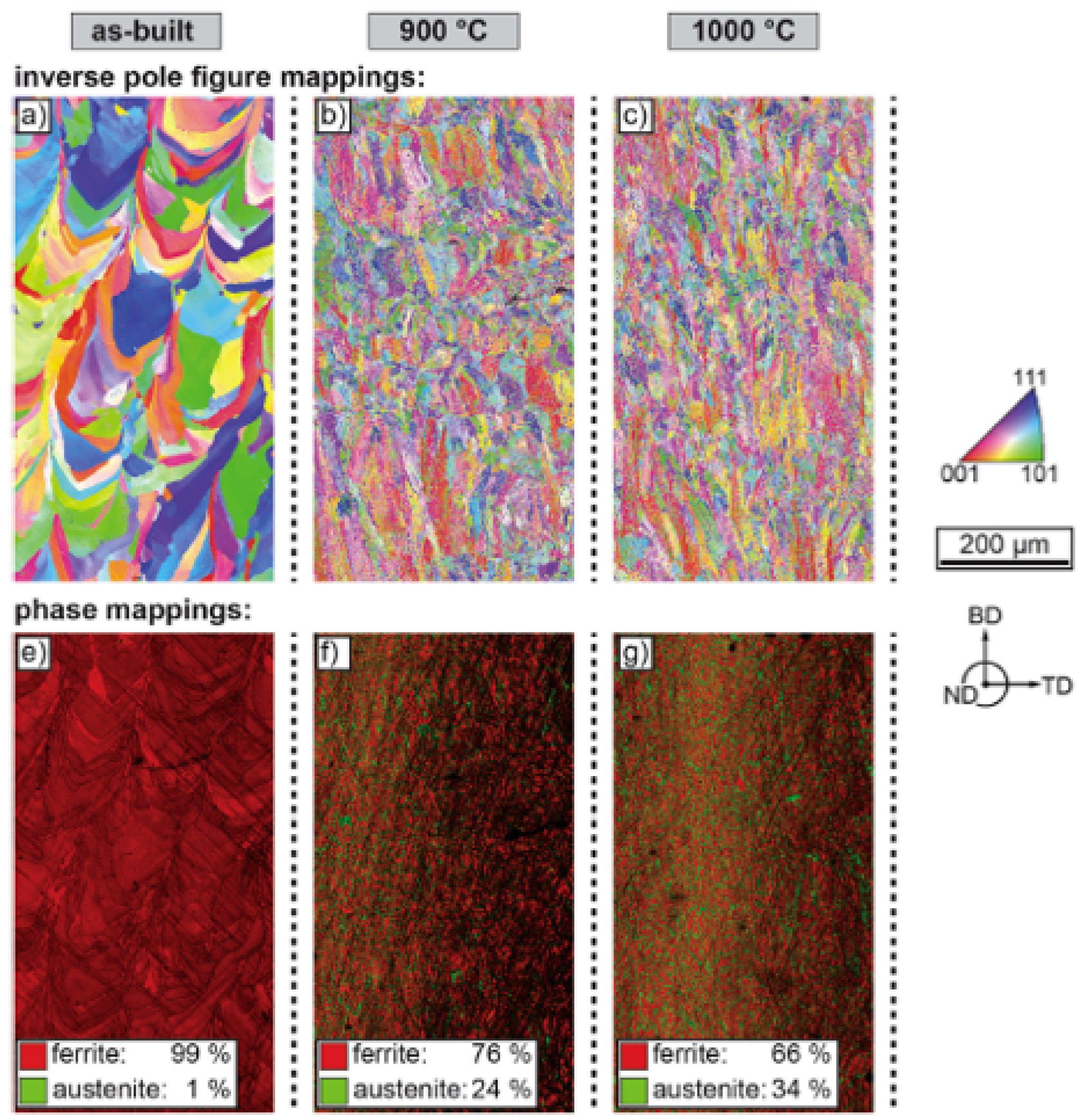
- The as-built SAF 2507 alloy is characterized by an almost completely ferritic microstructure (Figure 19a,e), strongly different from the desired microstructure, caused by rapid cooling rates typical of L-PBF. The cooling rates experienced cause the alloy’s solidification in delta ferrite, suppressing the austenite field;
- Proper heat treating conditions can restore an acceptable ferrite/austenite ratio; in particular, sample solubilization at 1000 °C (Figure 19c,g) made it possible to achieve a 34% austenite content;
- The performed tension tests (shown in Table 5) showed that L-PBF SAF2205 properly heat-treated satisfies the standard minimum requirements, while SAF2507 needs to be further optimized through subsequent heat treatment in order to achieve proper mechanical performances.
Table 6.
Tensile strength of duplex stainless steel alloys obtained from L-PBF, compared to standard reference values.
Table 6.
Tensile strength of duplex stainless steel alloys obtained from L-PBF, compared to standard reference values.
| Grade | Equipment | Relative Density [%] | Condition | BD | Test Cond. | YS [MPa] | UTS [MPa] | El. [%] | Ref. |
|---|---|---|---|---|---|---|---|---|---|
| SAF2205 | SLM Solutions 280HL | 99.7–99.85 | As built | V | RT | - | 940 | 12 | [146] |
| HT—1000 °C/0.083 h | - | 770 | 28 | ||||||
| SAF2507 | NR | NR | As built | - | RT | 1214 | 1321 | - | [118] |
| 1200 °C | - | 500 | 30 | ||||||
| SAF2507 | EOS M270 | 99 | HT—1200 °C/0.083 h | - | RT | - | 920 | 1.8 | [147] |
| 1200 °C | - | 400 | 20 | ||||||
| Standard Reference Values | |||||||||
| Grade | Condition | Test Cond. | YS [MPa] | UTS [MPa] | El. [%] | Ref. | |||
| SAF2205 | HT—1020–1100 °C + rapid cooling | RT | >450 | >620 | >25 | [148] | |||
| SAF2507 | HT—1025–1125 °C + rapid cooling | RT | >550 | >800 | >15 | ||||
BD—Building Direction; YS—Yield Strength; UTS—Ultimate Tensile Strength; El.—Elongation; NR—Non reported; RT—Room Temperature; HT—Heat-treated; H—Horizontal; V—Vertical; QT—Quench and Tempered.
4. Conclusions
The capability of L-PBF systems to process stainless steel alloys is reported in detail in this review, which therefore could be considered as a reference for all researchers and technologists involved in activities concerning stainless steel grades and L-PBF manufacturing. In fact, since research in this field has been receiving a strong impulse in recent years, it could be quite time-consuming for those people facing such topic for the first time.
The exploitation of the L-PBF technique makes it possible to achieve significant benefits when the following issues are required:
- Artefact weight reduction (made possible, for example, through topology optimization and/or lattice structures);
- Easy customization;
- Complex internal features manufacturing (e.g., inclined ducts).
The above-listed advantages, which are known to be relevant for high-cost alloys (such as superalloys or titanium alloys) and aerospace applications, are also significant for stainless steel grades, that, since their discovery, have found application in almost every field of application. In this context, the adoption of L-PBF reflects huge material savings and efficiency enhancement in applications ranging from biomedical devices to power production plants. L-PBF is particularly suited to additive manufacturing of stainless steels, since it makes it possible to produce complex features, in a wide range of cross-section thicknesses, with good compromise in terms of cost and time, while guaranteeing low oxides contamination. A variety of stainless steel grades coming from different classes (i.e., austenitic, martensitic, precipitation hardening and duplex) have been satisfactorily processed, meaning that it could be possible to widen the list of alloys in order to widen the field of applications.
This review shows that, to date, stainless steel alloys have been satisfactorily processed by L-PBF. Furthermore, the achieved mechanical properties make stainless steels fit the requirements of several applications. High mechanical properties are targeted, since the porosity level achieved by L-PBF is quite low and is comparable to conventionally processed materials. This statement is supported by the activities of many researchers, which has been demonstrated to satisfactorily achieve 99.9% relative density. Mechanical performances are even higher than the standard requirements, even if a wide range of values can be found in the literature, meaning that it is necessary to unify processing and post-processing routes. For example, standards defining the proper orientation to build and test samples, together with proper machine allowance and testing surface condition, still do not exist.
The analysis of the listed tested alloys, relative metallurgical microstructures and tensile strengths reveals a fundamental lack of alloys to be worked, standardization, and development of proper heat treatment. This inadequacy defines the path for further research and exploitation.
Funding
This research did not receive any specific grant from funding agencies in the public, commercial, or not-for-profit sectors.
Conflicts of Interest
The authors declare no conflict of interest.
References
- Zhai, Y.; Lados, D.A.; LaGoy, J.L. Additive Manufacturing: Making Imagination the Major Limitation. JOM 2014, 66, 808–816. [Google Scholar] [CrossRef] [Green Version]
- European Powder Metallurgy Association (EPMA)—Introduction to Additive Manufacturing Technology (Brochure). Available online: https://www.epma.com/epma-free-publications/product/introduction-to-additive-manufacturing-brochure (accessed on 3 August 2018).
- Orme, M.; Madera, I.; Gschweitl, M.; Ferrari, M. Topology Optimization for Additive Manufacturing as an Enabler for Light Weight Flight Hardware. Designs 2018, 2, 51. [Google Scholar] [CrossRef]
- Horn, T.J.; Harrysson, O.L.A. Overview of Current Additive Manufacturing Technologies and Selected Applications. Sci. Prog. 2012, 95, 255–282. [Google Scholar] [CrossRef] [PubMed]
- Shukla, M.; Todorov, I.; Kapletia, D. Application of additive manufacturing for mass customisation: Understanding the interaction of critical barriers. Prod. Plan. Control 2018, 29, 814–825. [Google Scholar] [CrossRef]
- Spallek, J.; Krause, D. Process Types of Customisation and Personalisation in Design for Additive Manufacturing Applied to Vascular Models. Procedia CIRP 2016, 50, 281–286. [Google Scholar] [CrossRef] [Green Version]
- Glasschroeder, J.; Prager, E.; Zaeh, M.F. Powder-bed-based 3D-printing of function integrated parts. Rapid Prototyp. J. 2015, 21, 207–215. [Google Scholar] [CrossRef]
- Sanín Pérez, P. A Study of Additive Manufacturing Applied to the Design and Production of LED Luminaires; Politecnico di Milano: Milano, Italy, 2013. [Google Scholar]
- Tang, Y.; Yang, S.; Zhao, Y.F. Sustainable Design for Additive Manufacturing through Functionality Integration and Part Consolidation. In Handbook of Sustainability in Additive Manufacturing; Muthu, S.S., Savalani, M.M., Eds.; Springer: Singapore, 2016; pp. 101–144. ISBN 978-981-10-0547-3. [Google Scholar]
- DebRoy, T.; Wei, H.L.; Zuback, J.S.; Mukherjee, T.; Elmer, J.W.; Milewski, J.O.; Beese, A.M.; Wilson-Heid, A.; De, A.; Zhang, W. Additive manufacturing of metallic components—Process, structure and properties. Prog. Mater. Sci. 2018, 92, 112–224. [Google Scholar] [CrossRef]
- Poprawe, R.; Hinke, C.; Meiners, W.; Schrage, J.; Bremen, S.; Merkt, S. SLM Production Systems: Recent Developments in Process Development, Machine Concepts and Component Design. In Advances in Production Technology; Brecher, C., Ed.; Springer International Publishing: Cham, Switzerland, 2015; pp. 49–65. ISBN 978-3-319-12303-5. [Google Scholar]
- Kellner, T. How 3D Printing Will Change Manufacturing. Available online: https://www.ge.com/reports/epiphany-disruption-ge-additive-chief-explains-3d-printing-will-upend-manufacturing/ (accessed on 15 April 2019).
- Wimpenny, D.I.; Pandey, P.M.; Kumar, L.J. (Eds.) Advances in 3D Printing & Additive Manufacturing Technologies; Springer: Singapore, 2017; ISBN 978-981-10-0811-5. [Google Scholar]
- Yang, L.; Hsu, K.; Baughman, B.; Godfrey, D.; Medina, F.; Menon, M.; Wiener, S. Additive Manufacturing of Metals: The Technology, Materials, Design and Production; Springer Series in Advanced Manufacturing; Springer International Publishing: Cham, Switzerland, 2017; ISBN 978-3-319-55127-2. [Google Scholar]
- Wohlers, T.; Gornet, T. History of Additive Manufacturing. Wohlers Rep. 2014, 24, 118. [Google Scholar]
- Gibson, I.; Rosen, D.; Stucker, B. Additive Manufacturing Technologies; Springer: New York, NY, USA, 2015; ISBN 978-1-4939-2112-6. [Google Scholar]
- Milewski, J.O. Additive Manufacturing of Metals; Springer Series in Materials Science; Springer International Publishing: Cham, Switzerland, 2017; Volume 258, ISBN 978-3-319-58204-7. [Google Scholar]
- Your Expert in Additive Manufacturing Since 25 Years. Available online: https://www.eos.info/about_eos/history (accessed on 19 April 2019).
- Deckard, C.R. Apparatus for Producing Parts by Selective Sintering. U.S. Patent 5,597,589, 28 January 1997. [Google Scholar]
- Park, J.H.; Kang, Y. Inclusions in Stainless Steels—A Review. Steel Res. Int. 2017, 88, 1700130. [Google Scholar] [CrossRef]
- Mapelli, C.; Nolli, P. Formation Mechanism of Non-Metallic Inclusions in Different Stainless Steel Grades. ISIJ Int. 2003, 43, 1191–1199. [Google Scholar] [CrossRef]
- Gokuldoss, P.K.; Kolla, S.; Eckert, J. Additive Manufacturing Processes: Selective Laser Melting, Electron Beam Melting and Binder Jetting—Selection Guidelines. Materials 2017, 10, 672. [Google Scholar] [CrossRef] [PubMed]
- Zhang, B.; Li, Y.; Bai, Q. Defect Formation Mechanisms in Selective Laser Melting: A Review. Chin. J. Mech. Eng. 2017, 30, 515–527. [Google Scholar] [CrossRef] [Green Version]
- Malekipour, E.; El-Mounayri, H. Common defects and contributing parameters in powder bed fusion AM process and their classification for online monitoring and control: A review. Int. J. Adv. Manuf. Technol. 2018, 95, 527–550. [Google Scholar] [CrossRef]
- Zadpoor, A. Frontiers of Additively Manufactured Metallic Materials. Materials 2018, 11, 1566. [Google Scholar] [CrossRef] [PubMed]
- Nilsson, J.O. Can mankind survive without stainless steel? Stainl. Steel World. 2014. 1–4. Available online: https://pdfs.semanticscholar.org/7bcf/2041cf93f4b5c3db7c7fe27b1d06d92f3602.pdf (accessed on 20 May 2019).
- Rufini, R.; Di Pietro, O.; Di Schino, A. Predictive Simulation of Plastic Processing of Welded Stainless Steel Pipes. Metals 2018, 8, 519. [Google Scholar] [CrossRef]
- Saha Podder, A.; Bhanja, A. Applications of Stainless Steel in Automobile Industry. Adv. Mater. Res. 2013, 794, 731–740. [Google Scholar] [CrossRef]
- Baddoo, N.R. Stainless steel in construction: A review of research, applications, challenges and opportunities. J. Constr. Steel Res. 2008, 64, 1199–1206. [Google Scholar] [CrossRef]
- Corradi, M.; Di Schino, A.; Borri, A.; Rufini, R. A review of the use of stainless steel for masonry repair and reinforcement. Constr. Build. Mater. 2018, 181, 335–346. [Google Scholar] [CrossRef]
- Di Schino, A. Analysis of heat treatment effect on microstructural features evolution in a micro-alloyed martensitic steel. Acta Metall. Slov. 2017, 22, 266–270. [Google Scholar] [CrossRef]
- Di Schino, A.; Di Nunzio, P.E. Metallurgical aspects related to contact fatigue phenomena in steels for back-up rolls. Acta Metall. Slov. 2017, 23, 62–71. [Google Scholar] [CrossRef]
- Di Schino, A.; Porcu, G. Metallurgical design and development of C125 grade for mild sour service application. In Proceedings of the Corrosion; NACE Corrosion Paper: San Diego, CA, USA, 2006; pp. 1–14. [Google Scholar]
- Kumar Sharma, D.; Filipponi, M.; Di Schino, A.; Rossi, F.; Castaldi, J. Corrosion behaviour of high temperature fuel cells: Issues for materials selection. Metalurgija 2019, 58, 347–351. [Google Scholar]
- Di Schino, A.; Di Nunzio, P.E.; Turconi, G.L. Microstructure evolution during tempering of martenite in e medium C steel. Mater. Sci. Forum 2007, 558, 1435–1441. [Google Scholar] [CrossRef]
- Cianetti, F.; Ciotti, M.; Palmieri, M.; Zucca, G. On the Evaluation of Surface Fatigue Strength of a Stainless-Steel Aeronautical Component. Metals 2019, 9, 455. [Google Scholar] [CrossRef]
- Talha, M.; Behera, C.K.; Sinha, O.P. A review on nickel-free nitrogen containing austenitic stainless steels for biomedical applications. Mater. Sci. Eng. C 2013, 33, 3563–3575. [Google Scholar] [CrossRef] [PubMed]
- Boulané-Petermann, L. Processes of bioadhesion on stainless steel surfaces and cleanability: A review with special reference to the food industry. Biofouling 1996, 10, 275–300. [Google Scholar] [CrossRef]
- Bregliozzi, G.; Ahmed, S.I.-U.; Di Schino, A.; Kenny, J.M.; Haefke, H. Friction and Wear Behavior of Austenitic Stainless Steel: Influence of Atmospheric Humidity, Load Range, and Grain Size. Tribol. Lett. 2004, 17, 697–704. [Google Scholar] [CrossRef]
- Di Schino, A.; Valentini, L.; Kenny, J.M.; Gerbig, Y.; Ahmed, I.; Haefke, H. Wear resistance of a high-nitrogen austenitic stainless steel coated with nitrogenated amorphous carbon films. Surf. Coat. Technol. 2002, 161, 224–231. [Google Scholar] [CrossRef]
- Di Schino, A.; Kenny, J.M.; Abbruzzese, G. Analysis of the recrystallization and grain growth processes in AISI 316 stainless steel. J. Mater. Sci. 2002, 37, 5291–5298. [Google Scholar] [CrossRef]
- Uriondo, A.; Esperon-Miguez, M.; Perinpanayagam, S. The present and future of additive manufacturing in the aerospace sector: A review of important aspects. Proc. Inst. Mech. Eng. Part G J. Aerosp. Eng. 2015, 229, 2132–2147. [Google Scholar] [CrossRef]
- Leach, R. Metrology for Additive Manufacturing. Available online: http://eprints.nottingham.ac.uk/33924/1/AM%20metrology%20for%20MC.pdf (accessed on 20 May 2019).
- Jurrens, K. Measurement Science and Standards for Metals-Based Additive Manufacturing. Available online: https://www.nrc.gov/docs/ML1815/ML18150A368.pdf (accessed on 20 May 2019).
- Slotwinski, J.A.; Garboczi, E.J. Metrology Needs for Metal Additive Manufacturing Powders. JOM 2015, 67, 538–543. [Google Scholar] [CrossRef] [Green Version]
- Mani, M.; Lane, B.M.; Donmez, M.A.; Feng, S.C.; Moylan, S.P. A review on measurement science needs for real-time control of additive manufacturing metal powder bed fusion processes. Int. J. Prod. Res. 2017, 55, 1400–1418. [Google Scholar] [CrossRef]
- Everton, S.K.; Hirsch, M.; Stravroulakis, P.; Leach, R.K.; Clare, A.T. Review of in-situ process monitoring and in-situ metrology for metal additive manufacturing. Mater. Des. 2016, 95, 431–445. [Google Scholar] [CrossRef]
- ASTM and ISO Additive Manufacturing Committees Approve Joint Standards under Partner Standards Developing Organization Agreement|www.astm.org. Available online: https://www.astm.org/cms/drupal-7.51/newsroom/astm-and-iso-additive-manufacturing-committees-approve-joint-standards-under-partner (accessed on 23 May 2019).
- Committee F42 on Additive Manufacturing Technologies. Available online: https://www.astm.org/COMMITTEE/F42.htm (accessed on 23 May 2019).
- Clayton, J.; Deffley, R. Optimising Metal Powders for Additive Manufacturing. Met. Powder Rep. 2014, 69, 14–17. [Google Scholar] [CrossRef]
- He, X.; DebRoy, T.; Fuerschbach, P.W. Alloying element vaporization during laser spot welding of stainless steel. J. Phys. Appl. Phys. 2003, 36, 3079–3088. [Google Scholar] [CrossRef]
- DebRoy, T.; David, S.A. Physical processes in fusion welding. Rev. Mod. Phys. 1995, 67, 85–112. [Google Scholar] [CrossRef]
- Kou, S. Welding Metallurgy, 2nd ed.; Wiley-Interscience: Hoboken, NJ, USA, 2003; ISBN 978-0-471-43491-7. [Google Scholar]
- Walton, O.R. Review of Adhesion Fundamentals for Micron-Scale Particles. KONA Powder Part. J. 2008, 26, 129–141. [Google Scholar] [CrossRef] [Green Version]
- Khairallah, S.A.; Anderson, A.T.; Rubenchik, A.; King, W.E. Laser powder-bed fusion additive manufacturing: Physics of complex melt flow and formation mechanisms of pores, spatter, and denudation zones. Acta Mater. 2016, 108, 36–45. [Google Scholar] [CrossRef] [Green Version]
- Kruth, J.P.; Wang, X.; Laoui, T.; Froyen, L. Lasers and materials in selective laser sintering. Assem. Autom. 2003, 23, 357–371. [Google Scholar] [CrossRef]
- Bidare, P.; Bitharas, I.; Ward, R.M.; Attallah, M.M.; Moore, A.J. Fluid and particle dynamics in laser powder bed fusion. Acta Mater. 2018, 142, 107–120. [Google Scholar] [CrossRef]
- Özel, T.; Arısoy, Y.M.; Criales, L.E. Computational Simulation of Thermal and Spattering Phenomena and Microstructure in Selective Laser Melting of Inconel 625. Phys. Procedia 2016, 83, 1435–1443. [Google Scholar] [CrossRef] [Green Version]
- Megahed, M.; Mindt, H.-W.; N’Dri, N.; Duan, H.; Desmaison, O. Metal additive-manufacturing process and residual stress modeling. Integr. Mater. Manuf. Innov. 2016, 5, 61–93. [Google Scholar] [CrossRef] [Green Version]
- Körner, C.; Attar, E.; Heinl, P. Mesoscopic simulation of selective beam melting processes. J. Mater. Process. Technol. 2011, 211, 978–987. [Google Scholar] [CrossRef]
- Conti, P.; Cianetti, F.; Pilerci, P. Parametric Finite Elements Model of SLM Additive Manufacturing process. Procedia Struct. Integr. 2018, 8, 410–421. [Google Scholar] [CrossRef]
- Manvatkar, V.; De, A.; DebRoy, T. Spatial variation of melt pool geometry, peak temperature and solidification parameters during laser assisted additive manufacturing process. Mater. Sci. Technol. 2015, 31, 924–930. [Google Scholar] [CrossRef]
- Gürtler, F.-J.; Karg, M.; Leitz, K.-H.; Schmidt, M. Simulation of Laser Beam Melting of Steel Powders using the Three-Dimensional Volume of Fluid Method. Phys. Procedia 2013, 41, 881–886. [Google Scholar] [CrossRef] [Green Version]
- King, W.E.; Anderson, A.T.; Ferencz, R.M.; Hodge, N.E.; Kamath, C.; Khairallah, S.A.; Rubenchik, A.M. Laser powder bed fusion additive manufacturing of metals; physics, computational, and materials challenges. Appl. Phys. Rev. 2015, 2, 041304. [Google Scholar] [CrossRef]
- Zhang, Z.; Huang, Y.; Rani Kasinathan, A.; Imani Shahabad, S.; Ali, U.; Mahmoodkhani, Y.; Toyserkani, E. 3-Dimensional heat transfer modeling for laser powder-bed fusion additive manufacturing with volumetric heat sources based on varied thermal conductivity and absorptivity. Opt. Laser Technol. 2019, 109, 297–312. [Google Scholar] [CrossRef]
- Foteinopoulos, P.; Papacharalampopoulos, A.; Stavropoulos, P. On thermal modeling of Additive Manufacturing processes. CIRP J. Manuf. Sci. Technol. 2018, 20, 66–83. [Google Scholar] [CrossRef]
- Rodgers, T.M.; Madison, J.D.; Tikare, V. Simulation of metal additive manufacturing microstructures using kinetic Monte Carlo. Comput. Mater. Sci. 2017, 135, 78–89. [Google Scholar] [CrossRef]
- Alimardani, M.; Toyserkani, E.; Huissoon, J.P. A 3D dynamic numerical approach for temperature and thermal stress distributions in multilayer laser solid freeform fabrication process. Opt. Lasers Eng. 2007, 45, 1115–1130. [Google Scholar] [CrossRef]
- Ganeriwala, R.; Zohdi, T.I. Multiphysics Modeling and Simulation of Selective Laser Sintering Manufacturing Processes. Procedia CIRP 2014, 14, 299–304. [Google Scholar] [CrossRef] [Green Version]
- Ren, K.; Chew, Y.; Fuh, J.Y.H.; Zhang, Y.F.; Bi, G.J. Thermo-mechanical analyses for optimized path planning in laser aided additive manufacturing processes. Mater. Des. 2019, 162, 80–93. [Google Scholar] [CrossRef]
- Alimardani, M.; Toyserkani, E.; Huissoon, J.P.; Paul, C.P. On the delamination and crack formation in a thin wall fabricated using laser solid freeform fabrication process: An experimental–numerical investigation. Opt. Lasers Eng. 2009, 47, 1160–1168. [Google Scholar] [CrossRef]
- Qiu, C.; Panwisawas, C.; Ward, M.; Basoalto, H.C.; Brooks, J.W.; Attallah, M.M. On the role of melt flow into the surface structure and porosity development during selective laser melting. Acta Mater. 2015, 96, 72–79. [Google Scholar] [CrossRef] [Green Version]
- Scime, L.; Beuth, J. Using machine learning to identify in-situ melt pool signatures indicative of flaw formation in a laser powder bed fusion additive manufacturing process. Addit. Manuf. 2019, 25, 151–165. [Google Scholar] [CrossRef]
- Coeck, S.; Bisht, M.; Plas, J.; Verbist, F. Prediction of lack of fusion porosity in selective laser melting based on melt pool monitoring data. Addit. Manuf. 2019, 25, 347–356. [Google Scholar] [CrossRef]
- Zhou, Y.H.; Zhang, Z.H.; Wang, Y.P.; Liu, G.; Zhou, S.Y.; Li, Y.L.; Shen, J.; Yan, M. Selective laser melting of typical metallic materials: An effective process prediction model developed by energy absorption and consumption analysis. Addit. Manuf. 2019, 25, 204–217. [Google Scholar] [CrossRef]
- Spierings, A.B.; Voegtlin, M.; Bauer, T.; Wegener, K. Powder flowability characterisation methodology for powder-bed-based metal additive manufacturing. Prog. Addit. Manuf. 2016, 1, 9–20. [Google Scholar] [CrossRef]
- Parry, L.A.; Ashcroft, I.A.; Wildman, R.D. Geometrical effects on residual stress in selective laser melting. Addit. Manuf. 2019, 25, 166–175. [Google Scholar] [CrossRef]
- Hitzler, L.; Hirsch, J.; Heine, B.; Merkel, M.; Hall, W.; Öchsner, A. On the Anisotropic Mechanical Properties of Selective Laser-Melted Stainless Steel. Materials 2017, 10, 1136. [Google Scholar] [CrossRef]
- Sames, W.J.; List, F.A.; Pannala, S.; Dehoff, R.R.; Babu, S.S. The metallurgy and processing science of metal additive manufacturing. Int. Mater. Rev. 2016, 61, 315–360. [Google Scholar] [CrossRef]
- Zhang, Y.; Wu, L.; Guo, X.; Kane, S.; Deng, Y.; Jung, Y.-G.; Lee, J.-H.; Zhang, J. Additive Manufacturing of Metallic Materials: A Review. J. Mater. Eng. Perform. 2018, 27, 1–13. [Google Scholar] [CrossRef]
- Herzog, D.; Seyda, V.; Wycisk, E.; Emmelmann, C. Additive manufacturing of metals. Acta Mater. 2016, 117, 371–392. [Google Scholar] [CrossRef]
- Concept Laser X LINE 2000R Metal Laser Melting System. Available online: https://www.concept-laser.de/fileadmin/Machine_brochures/CL_X_LINE_2000R_DS_EN_US_4_v1.pdf (accessed on 29 April 2019).
- Machine Search|Senvol. Available online: http://senvol.com/machine-search/ (accessed on 5 May 2019).
- MYSINT100, Stampante 3D a Fusione Laser Selettiva di Polvere Metallica. SISMA. Available online: https://www.sisma.com/prodotti/mysint100/ (accessed on 29 April 2019).
- MYSINT 300, Stampante 3D a Fusione Laser Selettiva di Polvere Metallica. SISMA. Available online: https://www.sisma.com/prodotti/mysint300/ (accessed on 29 April 2019).
- Ngo, T.D.; Kashani, A.; Imbalzano, G.; Nguyen, K.T.Q.; Hui, D. Additive manufacturing (3D printing): A review of materials, methods, applications and challenges. Compos. Part B Eng. 2018, 143, 172–196. [Google Scholar] [CrossRef]
- Cordova, L.; Campos, M.; Tinga, T. Assessment of Moisture Content and Its Influence on Laser Beam Melting Feedstock. In Proceedings of the Euro PM2017 Congress & Exhibition: European Annual Powder Metallurgy congress and exhibition, Milan, Italy, 1–5 October 2017. [Google Scholar]
- Zhao, X.; Song, B.; Zhang, Y.; Zhu, X.; Wei, Q.; Shi, Y. Decarburization of stainless steel during selective laser melting and its influence on Young’s modulus, hardness and tensile strength. Mater. Sci. Eng. A 2015, 647, 58–61. [Google Scholar] [CrossRef]
- Liverani, E.; Toschi, S.; Ceschini, L.; Fortunato, A. Effect of selective laser melting (SLM) process parameters on microstructure and mechanical properties of 316L austenitic stainless steel. J. Mater. Process. Technol. 2017, 249, 255–263. [Google Scholar] [CrossRef]
- Stugelmayer, E. Characterization of Process Induced Effects in Laser Powder Bed Fusion Processed AlSi10Mg alloy; Master of Science Degree, Montana Tech: Butte, MT, USA, 2018. [Google Scholar]
- Mercelis, P.; Kruth, J. Residual stresses in selective laser sintering and selective laser melting. Rapid Prototyp. J. 2006, 12, 254–265. [Google Scholar] [CrossRef]
- Li, C.; Liu, Z.Y.; Fang, X.Y.; Guo, Y.B. Residual Stress in Metal Additive Manufacturing. Procedia CIRP 2018, 71, 348–353. [Google Scholar] [CrossRef]
- Robinson, J.; Ashton, I.; Fox, P.; Jones, E.; Sutcliffe, C. Determination of the effect of scan strategy on residual stress in laser powder bed fusion additive manufacturing. Addit. Manuf. 2018, 23, 13–24. [Google Scholar] [CrossRef]
- Liu, B.; Wildman, R.; Tuck, C.R.; Ashcroft, I.; Hague, R.J.M. Investigaztion the Effect of Particle Size Distribution on Processing Parameters Optimisation in Selective Laser Melting Process; Additive Manufacturing Research Group, Loughborough University: Loughborough, UK, 2011. [Google Scholar]
- Clayton, J.; Millington-Smith, D.; Armstrong, B. The Application of Powder Rheology in Additive Manufacturing. JOM 2015, 67, 544–548. [Google Scholar] [CrossRef]
- Rausch, A.M.; Markl, M.; Körner, C. Predictive simulation of process windows for powder bed fusion additive manufacturing: Influence of the powder size distribution. Comput. Math. Appl. 2018, S0898122118303535. [Google Scholar] [CrossRef]
- Spierings, A.B.; Herres, N.; Levy, G. Influence of the particle size distribution on surface quality and mechanical properties in AM steel parts. Rapid Prototyp. J. 2011, 17, 195–202. [Google Scholar] [CrossRef] [Green Version]
- Dowson, G. Introduction to Powder Metallurgy—The Process and its Products; EPMA: Mannheim, Germany, 2008. [Google Scholar]
- Sames, W.J.; Medina, F.; Peter, W.H.; Babu, S.S.; Dehoff, R.R. Effect of Process Control and Powder Quality on Inconel 718 Produced Using Electron Beam Melting. In 8th International Symposium on Superalloy 718 and Derivatives; Ott, E., Banik, A., Andersson, J., Dempster, I., Gabb, T., Groh, J., Heck, K., Helmink, R., Liu, X., Wusatowska-Sarnek, A., Eds.; John Wiley & Sons, Inc.: Hoboken, NJ, USA, 2014; pp. 409–423. ISBN 978-1-119-01685-4. [Google Scholar]
- Popovich, A.; Sufiiarov, V.; Polozov, I.; Borisov, E.; Masaylo, D. Producing hip implants of titanium alloys by additive manufacturing. Int. J. Bioprinting 2016, 2, 78–84. [Google Scholar] [CrossRef]
- Choo, H.; Sham, K.-L.; Bohling, J.; Ngo, A.; Xiao, X.; Ren, Y.; Depond, P.J.; Matthews, M.J.; Garlea, E. Effect of laser power on defect, texture, and microstructure of a laser powder bed fusion processed 316L stainless steel. Mater. Des. 2019, 164, 107534. [Google Scholar] [CrossRef]
- Vrancken, B. Study of Residual Stresses in Selective Laser Melting. Ph.D. Thesis, KU Leuven—Faculty of Engineering Science, Leuven, Belgium, June 2016. [Google Scholar]
- Kamath, C.; El-dasher, B.; Gallegos, G.F.; King, W.E.; Sisto, A. Density of additively-manufactured, 316L SS parts using laser powder-bed fusion at powers up to 400 W. Int. J. Adv. Manuf. Technol. 2014, 74, 65–78. [Google Scholar] [CrossRef] [Green Version]
- Keshavarzkermani, A.; Marzbanrad, E.; Esmaeilizadeh, R.; Mahmoodkhani, Y.; Ali, U.; Enrique, P.D.; Zhou, N.Y.; Bonakdar, A.; Toyserkani, E. An investigation into the effect of process parameters on melt pool geometry, cell spacing, and grain refinement during laser powder bed fusion. Opt. Laser Technol. 2019, 116, 83–91. [Google Scholar] [CrossRef]
- Guan, K.; Wang, Z.; Gao, M.; Li, X.; Zeng, X. Effects of processing parameters on tensile properties of selective laser melted 304 stainless steel. Mater. Des. 2013, 50, 581–586. [Google Scholar] [CrossRef]
- Jeon, T.; Hwang, T.; Yun, H.; VanTyne, C.; Moon, Y. Control of Porosity in Parts Produced by a Direct Laser Melting Process. Appl. Sci. 2018, 8, 2573. [Google Scholar] [CrossRef]
- Wang, D.; Liu, Y.; Yang, Y.; Xiao, D. Theoretical and experimental study on surface roughness of 316L stainless steel metal parts obtained through selective laser melting. Rapid Prototyp. J. 2016, 22, 706–716. [Google Scholar] [CrossRef]
- Yadollahi, A.; Mahtabi, M.J.; Khalili, A.; Doude, H.R.; Newman, J.C. Fatigue life prediction of additively manufactured material: Effects of surface roughness, defect size, and shape. Fatigue Fract. Eng. Mater. Struct. 2018, 41, 1602–1614. [Google Scholar] [CrossRef]
- Fayazfar, H.; Salarian, M.; Rogalsky, A.; Sarker, D.; Russo, P.; Paserin, V.; Toyserkani, E. A critical review of powder-based additive manufacturing of ferrous alloys: Process parameters, microstructure and mechanical properties. Mater. Des. 2018, 144, 98–128. [Google Scholar] [CrossRef]
- Gu, D.; Shen, Y. Balling phenomena in direct laser sintering of stainless steel powder: Metallurgical mechanisms and control methods. Mater. Des. 2009, 30, 2903–2910. [Google Scholar] [CrossRef]
- Metelkova, J.; Kinds, Y.; Kempen, K.; de Formanoir, C.; Witvrouw, A.; Van Hooreweder, B. On the influence of laser defocusing in Selective Laser Melting of 316L. Addit. Manuf. 2018, 23, 161–169. [Google Scholar] [CrossRef]
- Bassoli, E.; Sola, A.; Celesti, M.; Calcagnile, S.; Cavallini, C. Development of Laser-Based Powder Bed Fusion Process Parameters and Scanning Strategy for New Metal Alloy Grades: A Holistic Method Formulation. Materials 2018, 11, 2356. [Google Scholar] [CrossRef] [PubMed]
- Mishurova, T.; Artzt, K.; Haubrich, J.; Requena, G.; Bruno, G. New aspects about the search for the most relevant parameters optimizing SLM materials. Addit. Manuf. 2019, 25, 325–334. [Google Scholar] [CrossRef]
- Bruna-Rosso, C.; Demir, A.G.; Previtali, B. Selective laser melting finite element modeling: Validation with high-speed imaging and lack of fusion defects prediction. Mater. Des. 2018, 156, 143–153. [Google Scholar] [CrossRef] [Green Version]
- Huang, Z.; Dantan, J.-Y.; Etienne, A.; Rivette, M.; Bonnet, N. Geometrical deviation identification and prediction method for additive manufacturing. Rapid Prototyp. J. 2018, 24, 1524–1538. [Google Scholar] [CrossRef] [Green Version]
- Hussain, B.; El-Gizawy, A.S. Development of 3D Finite Element Model for Predicting Process-Induced Defects in Additive Manufacturing by Selective Laser Melting (SLM). In Proceedings of the Volume 2: Advanced Manufacturing; ASME: Phoenix, ZA, USA, 2016; p. V002T02A065. [Google Scholar]
- Tang, H.P.; Qian, M.; Liu, N.; Zhang, X.Z.; Yang, G.Y.; Wang, J. Effect of Powder Reuse Times on Additive Manufacturing of Ti-6Al-4V by Selective Electron Beam Melting. JOM 2015, 67, 555–563. [Google Scholar] [CrossRef]
- Saeidi, K.; Akhtar, F. Microstructure-Tailored Stainless Steels with High Mechanical Performance at Elevated Temperature. In Stainless Steels and Alloys; Duriagina, Z., Ed.; IntechOpen: London, UK, 2019; ISBN 978-1-78985-369-8. [Google Scholar] [Green Version]
- Hooper, P.A. Melt pool temperature and cooling rates in laser powder bed fusion. Addit. Manuf. 2018, 22, 548–559. [Google Scholar] [CrossRef]
- Molinari, A. La metastabilità strutturale delle leghe metalliche ottenute per Selective Laser Melting. Metall. Ital. 2017, 21–27. [Google Scholar]
- Murr, L.E.; Gaytan, S.M.; Ramirez, D.A.; Martinez, E.; Hernandez, J.; Amato, K.N.; Shindo, P.W.; Medina, F.R.; Wicker, R.B. Metal Fabrication by Additive Manufacturing Using Laser and Electron Beam Melting Technologies. J. Mater. Sci. Technol. 2012, 28, 1–14. [Google Scholar] [CrossRef]
- EOS Metal Materials for Additive Manufacturing. Available online: https://www.eos.info/material-m (accessed on 20 April 2019).
- Renishaw Renishaw: Metal Powders Supply. Available online: http://www.renishaw.com/en/metal-powders-supply--31458 (accessed on 5 May 2019).
- SLM Solutions Group AG: SLM® Metal Powder. Available online: https://www.slm-solutions.com/en/products/accessories-consumables/slmr-metal-powder/ (accessed on 5 May 2019).
- Metal Materials. Available online: https://it.3dsystems.com/materials/metal (accessed on 21 April 2019).
- Materials Laser Melting—Concept Laser. Available online: https://www.concept-laser.de/en/products/materials.html (accessed on 30 March 2019).
- Nguyen, Q.B.; Zhu, Z.; Ng, F.L.; Chua, B.W.; Nai, S.M.L.; Wei, J. High mechanical strengths and ductility of stainless steel 304L fabricated using selective laser melting. J. Mater. Sci. Technol. 2019, 35, 388–394. [Google Scholar] [CrossRef]
- Marbury, F. Characterization of SLM Printed 316L Stainless Steel and Investigation of Micro Lattice Geometry; California Polytechnic State University: San Luis Obispo, CA, USA, 2017. [Google Scholar]
- Casati, R.; Lemke, J.; Vedani, M. Microstructure and Fracture Behavior of 316L Austenitic Stainless Steel Produced by Selective Laser Melting. J. Mater. Sci. Technol. 2016, 32, 738–744. [Google Scholar] [CrossRef]
- ASTM A276/A276M—Standard Specification for Stainless Steel Bars and Shapes; ASTM International: West Conshohocken, PA, USA, 2017.
- Spierings, A.B.; Starr, T.L.; Wegener, K. Fatigue performance of additive manufactured metallic parts. Rapid Prototyp. J. 2013, 19, 88–94. [Google Scholar] [CrossRef]
- Uhlmann, E.; Fleck, C.; Gerlitzky, G.; Faltin, F. Dynamical fatigue behavior of additive manufactured products for a fundamental life cycle approach. Procedia CIRP 2017, 61, 588–593. [Google Scholar] [CrossRef]
- Riemer, A.; Leuders, S.; Thöne, M.; Richard, H.A.; Tröster, T.; Niendorf, T. On the fatigue crack growth behavior in 316L stainless steel manufactured by selective laser melting. Eng. Fract. Mech. 2014, 120, 15–25. [Google Scholar] [CrossRef]
- Qiu, C.; Kindi, M.A.; Aladawi, A.S.; Hatmi, I.A. A comprehensive study on microstructure and tensile behaviour of a selectively laser melted stainless steel. Sci. Rep. 2018, 8, 7785. [Google Scholar] [CrossRef]
- Krakhmalev, P.; Fredriksson, G.; Svensson, K.; Yadroitsev, I.; Yadroitsava, I.; Thuvander, M.; Peng, R. Microstructure, Solidification Texture, and Thermal Stability of 316 L Stainless Steel Manufactured by Laser Powder Bed Fusion. Metals 2018, 8, 643. [Google Scholar] [CrossRef]
- Auguste, P.; Mauduit, A.; Fouquet, L.; Pillot, S. Study on 17-4 PH stainless steel produced by selective laser melting. UPB Sci. Bull. Ser. B-chem. Mater. Sci. 2018, 80, 197–210. [Google Scholar]
- Murr, L.E.; Martinez, E.; Hernandez, J.; Collins, S.; Amato, K.N.; Gaytan, S.M.; Shindo, P.W. Microstructures and Properties of 17-4 PH Stainless Steel Fabricated by Selective Laser Melting. J. Mater. Res. Technol. 2012, 1, 167–177. [Google Scholar] [CrossRef] [Green Version]
- Yadollahi, A.; Shamsaei, N.; Thompson, S.M.; Elwany, A.; Bian, L. Effects of building orientation and heat treatment on fatigue behavior of selective laser melted 17-4 PH stainless steel. Int. J. Fatigue 2017, 94, 218–235. [Google Scholar] [CrossRef]
- Mahmoudi, M.; Elwany, A.; Yadollahi, A.; Thompson, S.M.; Bian, L.; Shamsaei, N. Mechanical properties and microstructural characterization of selective laser melted 17-4 PH stainless steel. Rapid Prototyp. J. 2017, 23, 280–294. [Google Scholar] [CrossRef] [Green Version]
- Luecke, W.E.; Slotwinski, J.A. Mechanical Properties of Austenitic Stainless Steel Made by Additive Manufacturing. J. Res. Natl. Inst. Stand. Technol. 2014, 119, 398. [Google Scholar] [CrossRef] [PubMed]
- Nezhadfar, P.D.; Masoomi, M.; Thompson, S.; Pham, N.; Shamsaei, N. Mechanical Properties of 17-4 Ph Stainless Steel Additively Manufactured Under Ar and N2 Shielding Gas. In Proceedings of the 29th Annual International Solid Freeform Fabrication, Austin, TX, USA, 13–15 August 2018; p. 10. [Google Scholar]
- Ali, U.; Esmaeilizadeh, R.; Ahmed, F.; Sarker, D.; Muhammad, W.; Keshavarzkermani, A.; Mahmoodkhani, Y.; Marzbanrad, E.; Toyserkani, E. Identification and characterization of spatter particles and their effect on surface roughness, density and mechanical response of 17-4 PH stainless steel laser powder-bed fusion parts. Mater. Sci. Eng. A 2019, 756, 98–107. [Google Scholar] [CrossRef]
- Rafi, H.K.; Starr, T.L.; Stucker, B.E. A comparison of the tensile, fatigue, and fracture behavior of Ti–6Al–4V and 15-5 PH stainless steel parts made by selective laser melting. Int. J. Adv. Manuf. Technol. 2013, 69, 1299–1309. [Google Scholar] [CrossRef]
- ASTM A564/A564M—Standard Specification for Hot-Rolled and Cold-Finished Age-Hardening Stainless Steel Bars and Shapes; ASTM International: West Conshohocken, PA, USA, 2013.
- EN 10088-3: Stainless Steels—Part 3: Technical Delivery Conditions for Semi-Finished Products, Bars, Rods, Wire, Sections and Bright Products of Corrosion Resisting Steels for General Purposes; CEN-CENELEC Management Centre: Brussels, Belgium, 2014.
- Hengsbach, F.; Koppa, P.; Duschik, K.; Holzweissig, M.J.; Burns, M.; Nellesen, J.; Tillmann, W.; Tröster, T.; Hoyer, K.-P.; Schaper, M. Duplex stainless steel fabricated by selective laser melting—Microstructural and mechanical properties. Mater. Des. 2017, 133, 136–142. [Google Scholar] [CrossRef]
- Saeidi, K.; Alvi, S.; Lofaj, F.; Petkov, V.I.; Akhtar, F. Advanced Mechanical Strength in Post Heat Treated SLM 2507 at Room and High Temperature Promoted by Hard/Ductile Sigma Precipitates. Metals 2019, 9, 199. [Google Scholar] [CrossRef]
- ASTM A789/A789M—Standard Specification for Seamless and Welded Ferritic/Austenitic Stainless Steel Tubing for General Service; ASTM International: West Conshohocken, PA, USA, 2017.
Figure 1.
Schematics of a generic laser powder bed fusion system, adapted from [50], with permission from Elsevier, 2019.
Figure 1.
Schematics of a generic laser powder bed fusion system, adapted from [50], with permission from Elsevier, 2019.

Figure 2.
Main factors influencing process and part performances, and their inter-correlation.

Figure 3.
Schematic drawing of a generic pattern of single scan lines [78].
Figure 3.
Schematic drawing of a generic pattern of single scan lines [78].

Figure 4.
SEM images of porosity defects observed in L-PBF 316L samples: (a) low and (b) high magnification of incomplete fusion defect containing unmelted particles partially sintered; (c) gas pore; (d) cavity associated with residual stresses. From [89], with permission from Elsevier, 2019.
Figure 4.
SEM images of porosity defects observed in L-PBF 316L samples: (a) low and (b) high magnification of incomplete fusion defect containing unmelted particles partially sintered; (c) gas pore; (d) cavity associated with residual stresses. From [89], with permission from Elsevier, 2019.

Figure 5.
Examples of different scanning strategies on a rectangular cross section—the direction of scan lines inside the red areas can vary from layer to layer, selecting a non-zero rotation angle (according to Figure 3) between subsequent layers.
Figure 5.
Examples of different scanning strategies on a rectangular cross section—the direction of scan lines inside the red areas can vary from layer to layer, selecting a non-zero rotation angle (according to Figure 3) between subsequent layers.

Figure 6.
Comparison of metal powder obtained from different production processes. Gas atomized particles [99]: (a) SEM image 100×; (b) SEM image at 500×; (c) LOM of GA particles in the metallographic section. Plasma atomized particles [100]: (d) SEM image at 500×; (e) SEM image 1000×; with permission from John Wiley and Sons, 2019.


Figure 7.
OM of L-PBF stainless steel 304 samples on cross-section and vertical section: (a,b) at an overlap rate of 0% showing full density, like (c,d) obtained with 50% overlap between parallel lines. From [105], with permission from Elsevier, 2019.
Figure 7.
OM of L-PBF stainless steel 304 samples on cross-section and vertical section: (a,b) at an overlap rate of 0% showing full density, like (c,d) obtained with 50% overlap between parallel lines. From [105], with permission from Elsevier, 2019.

Figure 8.
Schematics of commonly projected building directions for tensile specimens.

Figure 9.
OM micrographs showing the microstructure of 316L samples fabricated at 200 W laser power, using different scanning strategies: (a) Meander; (b) Stripe; (c) Chess with 5 mm × 5 mm islands; (d) Chessboard with 1 mm × 1 mm islands. Z specifies the building direction [134].
Figure 9.
OM micrographs showing the microstructure of 316L samples fabricated at 200 W laser power, using different scanning strategies: (a) Meander; (b) Stripe; (c) Chess with 5 mm × 5 mm islands; (d) Chessboard with 1 mm × 1 mm islands. Z specifies the building direction [134].

Figure 10.
OM micrographs of L-PBF 316L microstructure produced at different laser powers, (a) 200 W; (b) 170 W; (c) 140 W; (d) grain width correlation to laser power values. Z specifies the building direction [134].
Figure 10.
OM micrographs of L-PBF 316L microstructure produced at different laser powers, (a) 200 W; (b) 170 W; (c) 140 W; (d) grain width correlation to laser power values. Z specifies the building direction [134].

Figure 11.
OM showing L-PBF 304 stainless steel microstructure: (a) along the vertical cross-section—the heat flow effect is evident in the build direction, and (b) nearly equiaxed grains in the planar direction, coincident to the layer top view. From [127], with permission from Elsevier, 2019.
Figure 11.
OM showing L-PBF 304 stainless steel microstructure: (a) along the vertical cross-section—the heat flow effect is evident in the build direction, and (b) nearly equiaxed grains in the planar direction, coincident to the layer top view. From [127], with permission from Elsevier, 2019.

Figure 12.
SEM micrographs showing the microstructure of 316L samples (laser power at 200 W): (a) within a weld bead; (b) at the bottom region of (a); (c) grain structure beyond two layers; (d) grains in two adjacent weld beads. Red arrows point out grain growth direction. Z specifies the building direction [134].

Figure 13.
SEM images showing cross-section microstructures at melt-pool level of L-PBF 316 L steel in (a) as-built condition, and after annealing at (b) 800 °C/15 min and (c) 900 °C/15 min [135].
Figure 13.
SEM images showing cross-section microstructures at melt-pool level of L-PBF 316 L steel in (a) as-built condition, and after annealing at (b) 800 °C/15 min and (c) 900 °C/15 min [135].

Figure 14.
(a,b) OM cross-section observation of two 17-4 PH samples obtained from L-PBF, starting from different powder batches [136].
Figure 14.
(a,b) OM cross-section observation of two 17-4 PH samples obtained from L-PBF, starting from different powder batches [136].

Figure 15.
OM cross-section observation of L-PBF 17-4 PH sample (seen in Figure 14a) after heat treatment: (a) tempered at 480 °C/1 h; (b) tempered at 550 °C/4 h; (c) solution heat-treated (1040 °C/1.5 h), quenched and tempered at 480 °C/1 h; (d) homogenized (1190 °C/2 h), solution heat-treated (1040 °C/1.5 h) and tempered at 480 °C/1 h [136].

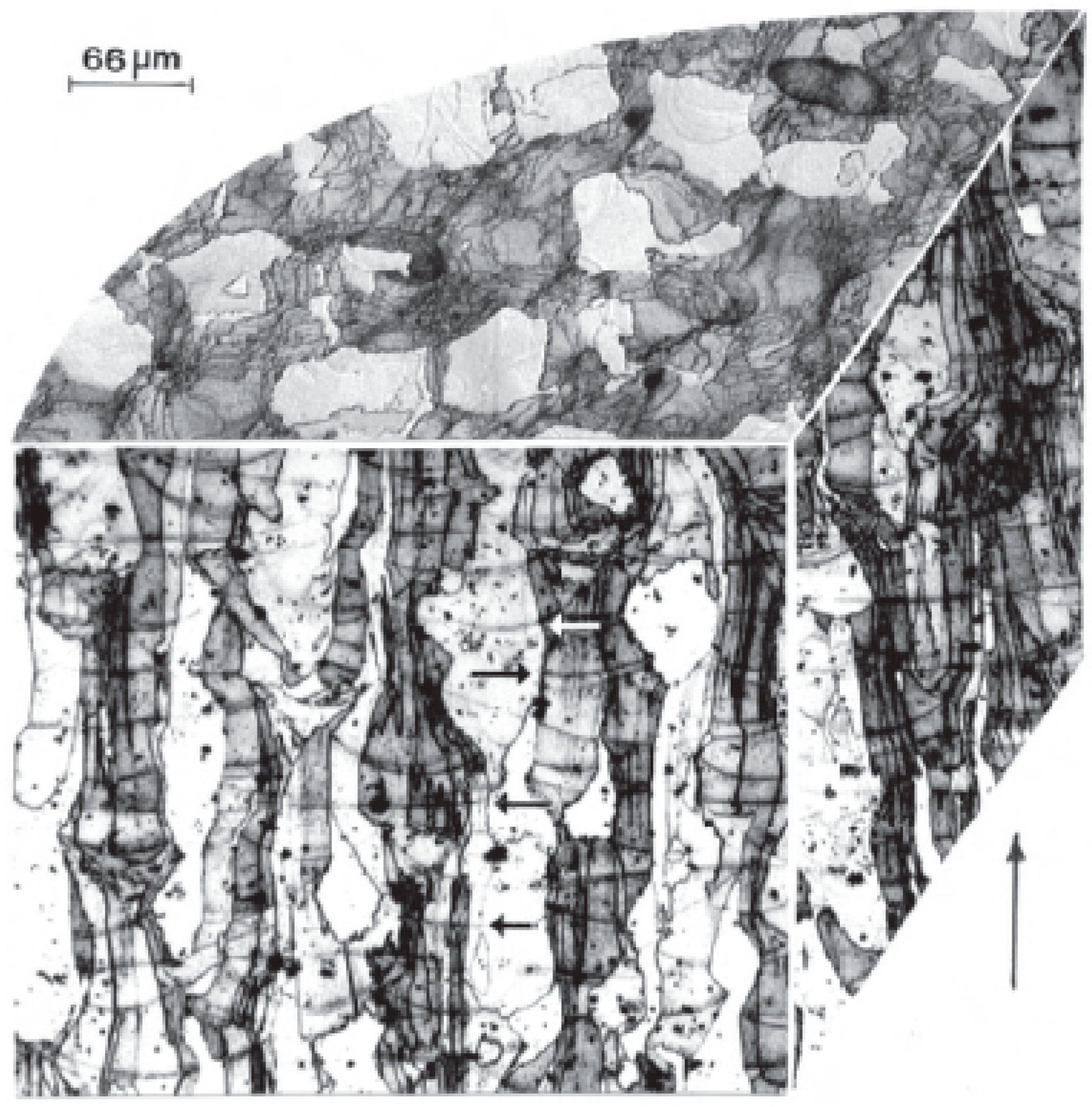
Figure 16.
OM-3D reconstruction of 17-4 PH sample, effective building direction shown by vertical arrow in the lower right corner: the microstructure is fully martensitic and comes from Ar-atomized powders fabricated in an Ar-rich environment (Ar/Ar) [137].
Figure 16.
OM-3D reconstruction of 17-4 PH sample, effective building direction shown by vertical arrow in the lower right corner: the microstructure is fully martensitic and comes from Ar-atomized powders fabricated in an Ar-rich environment (Ar/Ar) [137].

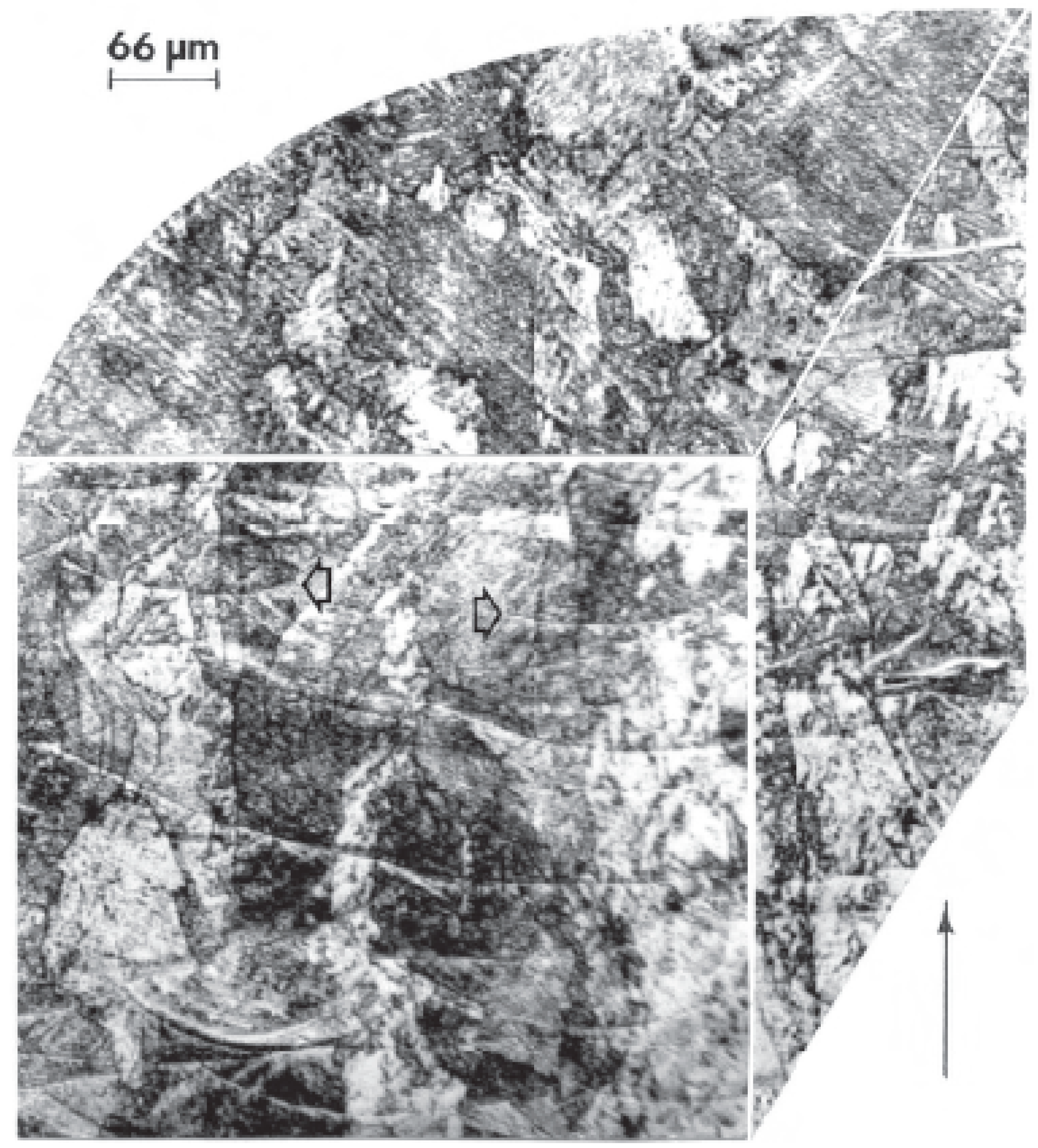
Figure 17.
OM-3D reconstruction of 17-4 PH sample, effective building direction shown by vertical arrow in the lower right corner: the microstructure is mainly austenitic, with a minor volume fraction of martensite (15%) and comes from N2-atomized powders fabricated in a N2-rich environment (N2/N2) [137].

Figure 18.
Experimental results from [137]: Vickers microhardness (HV) on as-manufactured samples (blue piles) and after aging at 482 °C for 1 h and air-cooled standard H900 heat treatment (green piles). Ar/Ar and N2/Ar refer respectively to Ar- and N2-atomized powders, both L-PBF processed in Ar atmosphere; similarly, Ar/N2 and N2/N2 refer to Ar- and N2-atomized powders, L-PBF fabricated in N2 environment.

Figure 19.
EBSD maps of duplex 2205 showing (a–c) inverse pole maps and (e–g) corresponding phase fraction, in (a,e) as-built condition, (b,f) after annealing at 900 °C, and (c,g) after annealing at 1000 °C [146], with permission from Elsevier, 2019.
Figure 19.
EBSD maps of duplex 2205 showing (a–c) inverse pole maps and (e–g) corresponding phase fraction, in (a,e) as-built condition, (b,f) after annealing at 900 °C, and (c,g) after annealing at 1000 °C [146], with permission from Elsevier, 2019.

Table 3.
Fatigue endurance limits of L-PBF 316L samples, under different loading and surface conditions.
Table 3.
Fatigue endurance limits of L-PBF 316L samples, under different loading and surface conditions.
| Alloy | Fatigue Endurance at 106 Cycles [MPa] | R | Surface Condition | Ra [µm] | Ref. |
|---|---|---|---|---|---|
| 316L | 130 | −1 | As built | 13.29 | [132] |
| 316L | 170 | −1 | Vibratory finished | 1.74 | |
| 316L | 240 | −1 | Turned | 1.08 | |
| 316L | 200 | 0.1 | As built | 10.0 | [131] |
| 316L | 256 | 0.1 | Machined | 0.4 | |
| 316L | 269 | 0.1 | Polished | 0.1 | |
| 316L | 108 | −1 | As built | NR | [133] |
| 316L | 267 | −1 | Turned | NR |
Table 4.
Tensile strength of precipitation hardening stainless steel grades obtained from L-PBF, compared to standard reference values.
Table 4.
Tensile strength of precipitation hardening stainless steel grades obtained from L-PBF, compared to standard reference values.
| Grade | Equipment | Relative Density [%] | Condition | BD | Test Cond. | YS [MPa] | UTS [MPa] | El. [%] | Ref. |
|---|---|---|---|---|---|---|---|---|---|
| 17-4 PH | EOS M270 | NR | As built | H | RT | 523 | 1028 | - | [140] |
| V | 494 | 979 | - | ||||||
| HT—650 °C/1 h | H | 436 | 1295 | - | |||||
| V | 483 | 1298 | - | ||||||
| 17-4 PH | EOS M290 | NR | As built | V | RT | 835 | 1169 | 48.42 | [141] |
| HT—1050 °C/0.5 h + 552 °C/4 h | 1176 | 1170 | 32.7 | ||||||
| 17-4 PH | SLM Solutions 280HL | >99 average 99.6 | As built | H | RT | 850 | 890 | 13 | [136] |
| V | 760 | 785 | 2.5 | ||||||
| HT—480 °C/1 h | H | - | 780 | - | |||||
| V | - | 560 | - | ||||||
| HT—550 °C/4 h | H | 1210 | 1220 | 0.5 | |||||
| V | - | 550 | - | ||||||
| HT—1040 °C/1.5 h + quenching + 480 °C/1 h | H | 785 | 990 | 4.6 | |||||
| V | 590 | 680 | 1 | ||||||
| HT—1190 °C/2 h + 1040 °C/1.5 h + quenching + 480 °C/1 h | H | 1400 | 1295 | 3 | |||||
| V | 1240 | 1305 | 1 | ||||||
| 17-4 PH | EOS M290 | NR | As built | H | RT | - | 710 | 6.7–7.2 | [142] |
| 17-4 PH | 3D Systems ProX 100 | NR | As-built | H | RT | 650 | 1050 | 9.8 | [139] |
| V | 600–720 | 950–1050 | 3.5–6.4 | ||||||
| HT—1038 °C/0.5 h + 482 °C/1 h | H | 910 | 1220 | 7.8 | |||||
| V | 730–950 | 970–1120 | 2.5–3.5 | ||||||
| 15-5 PH | EOS M270 | NR | As built | H | RT | 1297 | 1450 | 12.53 | [143] |
| V | 1100 | 1467 | 14.92 | ||||||
| Standard Reference Values | |||||||||
| Grade | Condition | Test Condition | YS [MPa] | UTS [MPa] | El. [%] | Ref. | |||
| 17-4 PH | H900 aging—482 °C/1 h | RT | >1170 | >1310 | >10 | [144] | |||
| 15-5 PH | H900 aging—482 °C/1 h | RT | >1170 | >1310 | >6 (transv.) | ||||
| >10 (long.) | |||||||||
BD—Building Direction; YS—Yield Strength; UTS—Ultimate Tensile Strength; El.—Elongation; NR—Non reported; HT—Heat-treated; H—Horizontal; V—Vertical; RT—Room Temperature.
Table 5.
Tensile strength of martensitic 420 alloy obtained from L-PBF, compared to standard reference values.
Table 5.
Tensile strength of martensitic 420 alloy obtained from L-PBF, compared to standard reference values.
| Grade | Equipment | Relative Density [%] | Cond. | BD | Test Cond. | YS [MPa] | UTS [MPa] | El. [%] | Ref. | |
|---|---|---|---|---|---|---|---|---|---|---|
| 420 | NR | NR | As built | RT | 800 | 1800 | 5 | [118] | ||
| 420 | SD | NR | As built | H | RT | - | 505 | - | [88] | |
| V | - | 1045 | - | |||||||
| Standard Reference Values | ||||||||||
| Grade | Condition | Test Condition | YS [MPa] | UTS [MPa] | El. [%] | Ref. | ||||
| 420 | Annealed—holding T: 745–825 °C + air cooling | RT | - | <760 | - | [145] | ||||
| QT800—quench at 950–1050 °C + oil or air cooling + tempering at 600–700 °C | >600 | 800–950 | >12 | |||||||
Cond.—Condition; BD—Building Direction; YS—Yield Strength; UTS—Ultimate Tensile Strength; El.—Elongation; SD—Self-developed; NR—Non reported; RT—Room Temperature; HT—Heat-treated; H—Horizontal; V—Vertical; QT—Quench and Tempered.
© 2019 by the authors. Licensee MDPI, Basel, Switzerland. This article is an open access article distributed under the terms and conditions of the Creative Commons Attribution (CC BY) license (http://creativecommons.org/licenses/by/4.0/).
Share and Cite
MDPI and ACS Style
Zitelli, C.; Folgarait, P.; Di Schino, A. Laser Powder Bed Fusion of Stainless Steel Grades: A Review. Metals 2019, 9, 731. https://0-doi-org.brum.beds.ac.uk/10.3390/met9070731
AMA Style
Zitelli C, Folgarait P, Di Schino A. Laser Powder Bed Fusion of Stainless Steel Grades: A Review. Metals. 2019; 9(7):731. https://0-doi-org.brum.beds.ac.uk/10.3390/met9070731
Chicago/Turabian StyleZitelli, Chiara, Paolo Folgarait, and Andrea Di Schino. 2019. "Laser Powder Bed Fusion of Stainless Steel Grades: A Review" Metals 9, no. 7: 731. https://0-doi-org.brum.beds.ac.uk/10.3390/met9070731
Note that from the first issue of 2016, this journal uses article numbers instead of page numbers. See further details here.