Ultrasonic Assessment of the Concrete Residual Strength after a Real Fire Exposure


1
Faculty of Civil Engineering, Wrocław University of Science and Technology, 50-370 Wrocław, Poland
2
Faculty of Environmental Engineering and Geodesy, Institute of Building Engineering, Wrocław University of Environmental and Life Sciences, 50-363 Wrocław, Poland
*
Author to whom correspondence should be addressed.
Buildings 2020, 10(9), 154; https://0-doi-org.brum.beds.ac.uk/10.3390/buildings10090154
Submission received: 29 May 2020
/
Revised: 22 August 2020
/
Accepted: 28 August 2020
/
Published: 2 September 2020
(This article belongs to the Special Issue Non-destructive Testing for Building Evaluation)
Abstract
:After a fire, the assessment of concrete residual strength can be a challenge. Since the strength reduction depends on the distance from the heated surface examination based on destructive test, i.e., core samples, is not precise enough. Therefore, more detailed methods can establish the influence of the high temperature in the zone, which no longer has visible cracks. That method can be used to assess layer thickness to remove due to the fire damage. The Ultrasound Pulse Velocity (UPV) method with point heads was used in the paper to examine samples taken from a structure after the real fire. Moreover, to make the analysis more precise, an effect associated with the porosity in concrete was also considered to separate pure fire effect.
1. Introduction
The fire temperature influence on steel, concrete, as well as the bond between both materials, is considerably different. With the increase of temperature and the length of its duration, the usefulness of concrete and reinforced concrete decreases mainly due to the following processes [1,2,3]:
- evaporation of free water and dissociation of ettringite up to 100 °C;
- dehydration of cement binder (decomposition of portlandite) at a temperature above 400 °C;
- decarbonisation of the binder at a temperature of about 700 °C;
- thermal deformation of materials: aggregate and reinforcing steel;
- crack net formation accompanying the rapid evaporation of water.
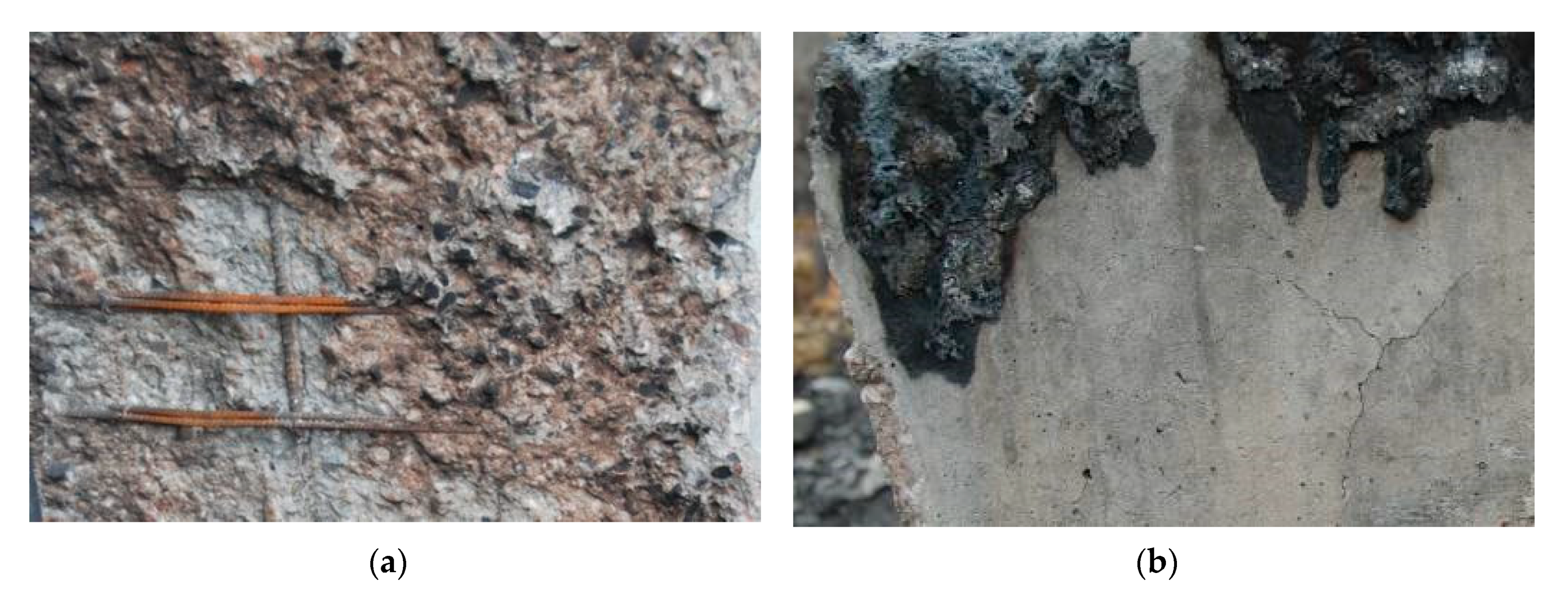
The time of temperature interaction in the structure is very diverse; thus, the effects of concrete heating and cooling are different. Moreover, sudden changes in temperature, e.g., when pouring hot concrete with water, the concrete cracks, splits, breaks, and destroys (Figure 1).
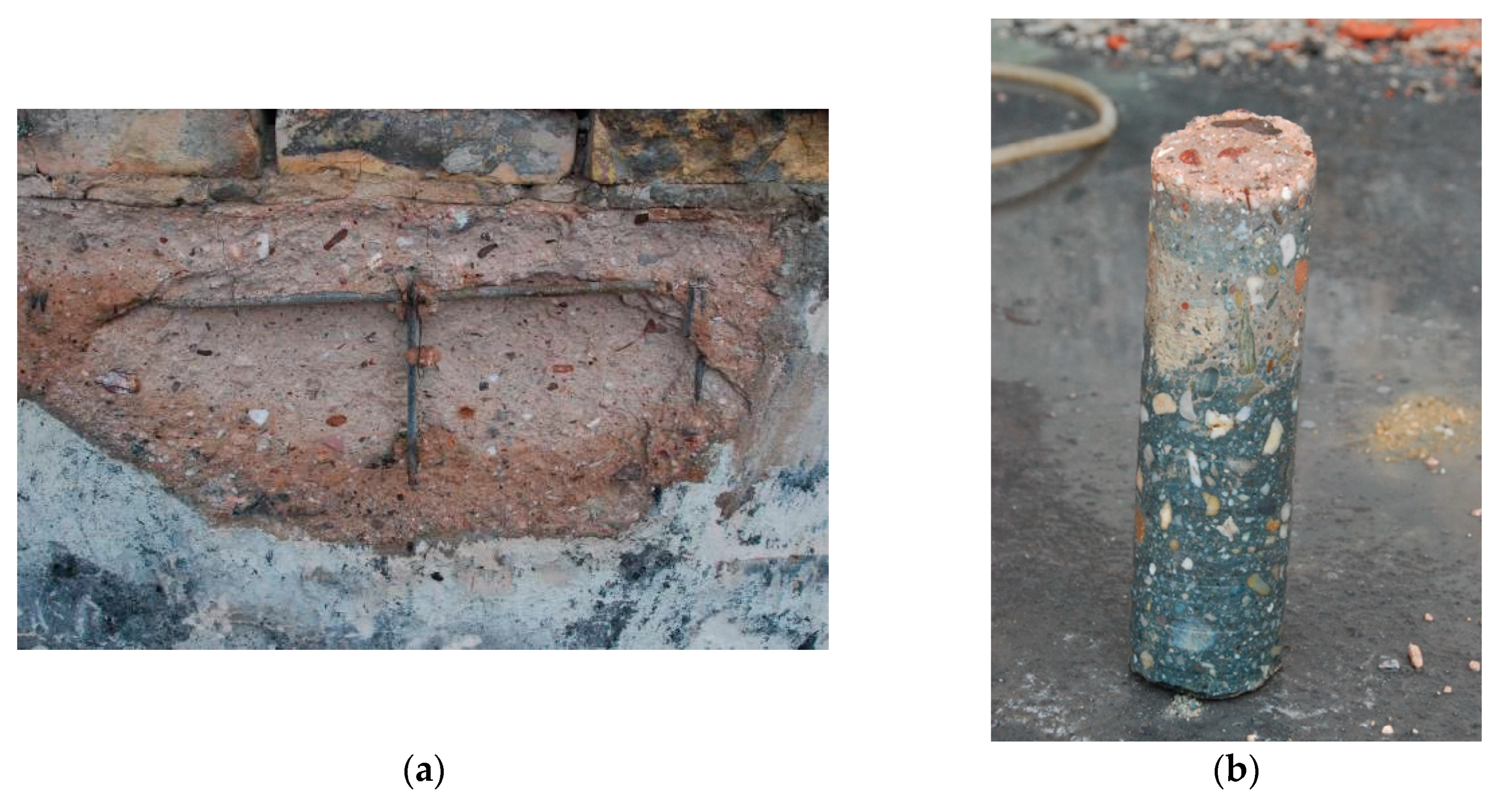
If cracked or not, the surface of concrete can be unavailable for direct observation when covered with remains of bituminous material or thermal isolation (Figure 2). Some information can be drawn from the concrete colour change [4] as presented in Figure 3. However, after the fire, the crucial question is what is the concrete strength in the zone, which no longer has visible cracks, or the cracks are different than the fire origin.
There are significant differences between material properties and structural behaviour in ambient and high-temperature. Therefore, in the analysis at ambient temperature, a set of simplifying assumptions on material behaviour (e.g., small strains and deformations, constant strength, thermal expansion, and elasticity modulus) can be made, which are no longer valid in the fire conditions [5]. Furthermore, in design, fire loading should be handled differently than other loads (e.g., live, gravity loads can be constant in time); consequently, the analysis is substituted, with passive fire protection arrangements. Moreover, the fire resistance is conventionally assessed in reference to the standard heating regime, which is unlikely to appear in real fires.
Besides strength, during the fire, the post-fire concrete strength analysed in the paper can be vital information. The paper is based on experimental evaluation of residual compressive strength of concrete and it combines destructive and non-destructive methods. A natural effect associated with the porosity change in conventional concrete is also considered as an important effect of the research. Although, that effect can be avoided as presented in [6,7] but at present, the application of nanoparticles is of limited use in practice.
The behaviour of structural materials and structures under the fire conditions is widely examined, tested, and simulated. Attempts are made to test concrete after treatment in high temperatures, but usually these are furnace tests. Concrete strength after the real fire is rarely analysed. Table 1 summarises references and problems related to the paper.
The material properties at elevated temperatures are discussed in general publications [1,2,9,12], detailed research [3,8,10,13] and design recommendations [30]. The behaviour of structures in various limit states are also examined [11] and tested. However, to date, there is a dearth of information on the real fires. Real fires are described in terms of their cause, results, and fire impact on a structure as presented for example in [9]. In the real fires, large buildings are subjected to traveling fires resulting in structural response varying in space, so evaluation of the fire influence on the structure can be made based on the fire results as a material deterioration (such as concrete and steel strength), damage, or destruction [1,3,9,11].
This leads to the work reported in the paper where deterioration of concrete strength after a real fire is examined. This deterioration is a function of peak temperature, time of heating, heating rate and cooling regime [1,2].
The use of literature information (e.g., [14,15,18]) when assessing concrete after the real fire is directly of little use, as there is generally not known precisely enough, neither the temperature nor the time of its impact. Moreover, strength reduction is very divergent due to varying temperature and unaffected concrete properties distributions. However, information on the speed of temperature spread in concrete and steel surrounded by concrete can be used when the strength is already known [5,8,9,13,16,17,26]. Then, steel and bond strength can be evaluated.
Undoubtedly, core samples can be used to test the strength of concrete in the structure after a fire, but in this case, the problem of the size of the samples appears [28]. Strength examined on these samples corresponds to the strength in the middle of their height, which is a distant zone from the heated surface (i.e., ~50 mm for the 100 mm sample) [22,25]. When the fire interacts with the structure on one side only, it is expected that damage to the concrete structure will be greater at the surface than in the deeper layers, i.e., more distant from the fire.
Several non-destructive methods have been used to examine concrete damages and deterioration after the fire exposure [21,23,24]. Most of them lead to an assessment of the exposure temperature and structural damages. However, to test residual strength rebound number [22] and Ultrasound Pulse Velocity (UPV) methods can be successfully used [19,20,22,23,25] up to 600 °C [20,22]. This is due to the temperature effect on both the elasticity modulus and the moisture content [23]. Moreover, the concrete mix proportion has been found insignificant [22].
The paper presents the application of the Ultrasound Pulse Velocity (UPV) method for the evaluation of post-fire concrete strength over the sample depths. The method is validated in the standard tests and the important effect associated with natural porosity is considered.
2. Basic Information on the Case of Study
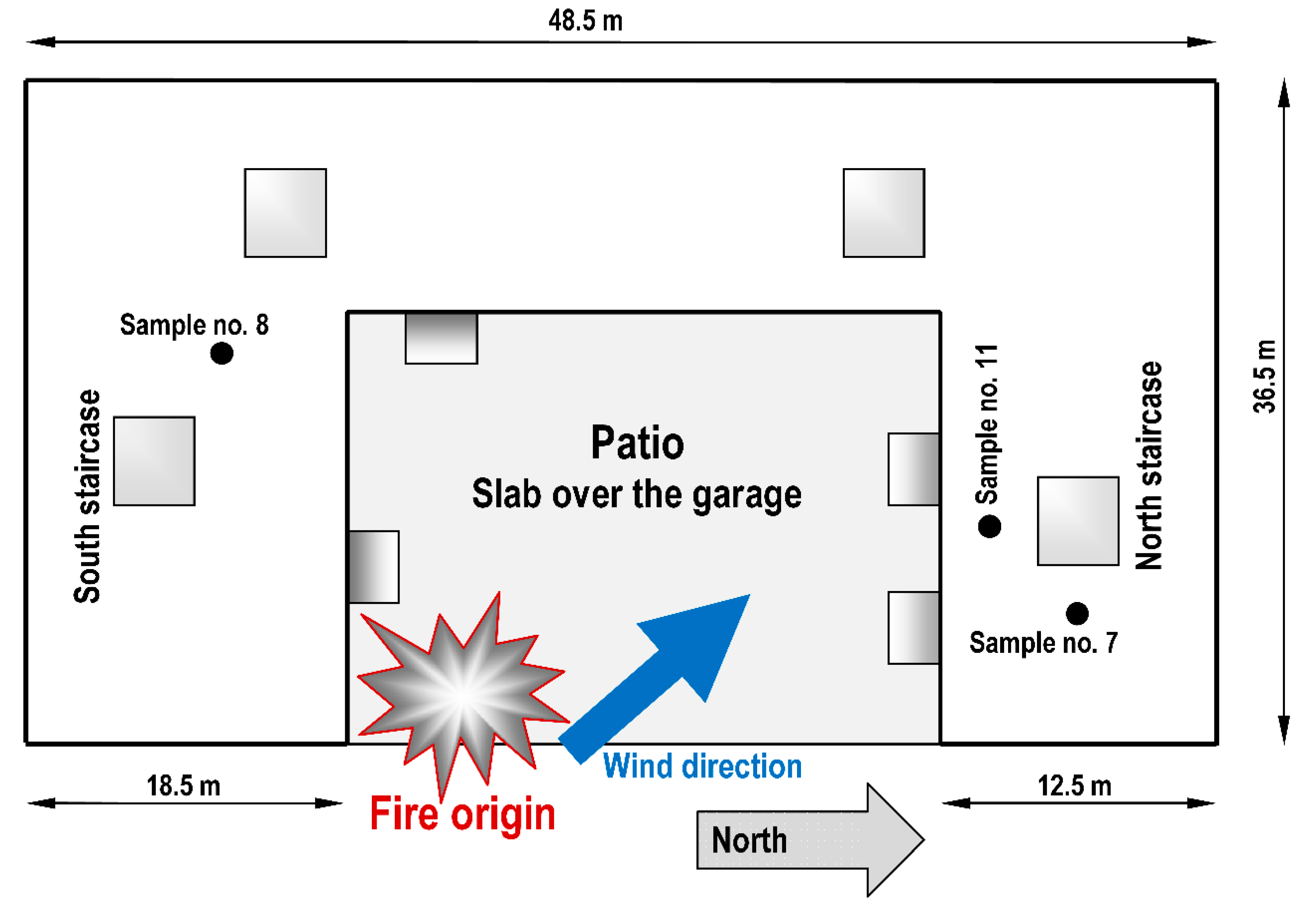
The fire appeared in the 64-apartment building under construction presented in Figure 4 and Figure 5. Weather conditions favoured the fire spread, i.e.:
- the air temperature—(26 °C);
- no precipitation;
- the air humidity—(36%);
- the average speed of the southeast wind—(9 m/s).
The building was designed as mixed reinforced concrete (RC)/masonry structure, i.e., cast in place reinforced concrete ceilings, columns and masonry (silicate), and RC walls. The stairs and balconies were made of precast RC elements. The fire resistance of the reinforced concrete structure was assumed in the design as R240. The damages of the building after the fire and firefighting were visually and instrumentally checked and inventoried, i.e.:
- concrete cracking and spalling;
- concrete compressive strength (reported in the paper);
- reinforcing steel strength;
- masonry walls cracking;
- silicate element compressive strength;
- load test;
- deposition of chemical substances on the building elements;
- material moisture.
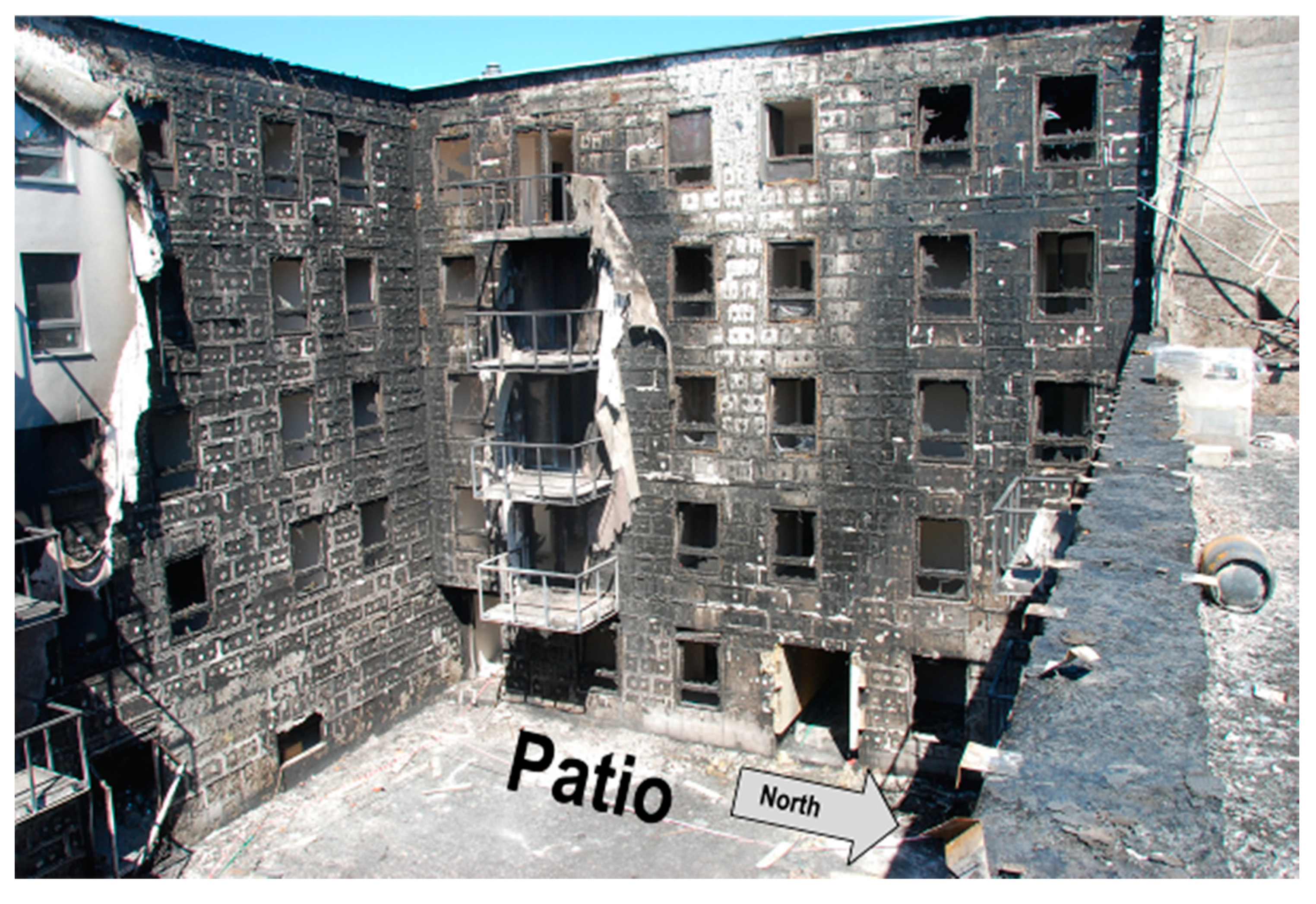
The effects of the fire were mainly observed outside the building within the patio of four staircases (Figure 4 and Figure 5). i.e., on the top surface of the slab above the garage, façades surrounding the patio and on the roofs of the northern and southern parts. To a much lesser extent, the effects were also visible in some rooms adjacent to the patio. The remaining part of the building (also all staircases) was not exposed to the fire.
On the slab above the garage, where the fire was the most intense, large amounts of building materials were stored. There were mainly Styrofoam and roofing paper, which indicate the hydrocarbon nature of the fire. That type of fire course rapidly and temperature increases very fast. The roofing paper and polyvinyl chloride (PVC windows) burn at a temperature of about 200 °C, and polystyrene (wall thermal insulation) at about 350 °C. The range and type of damages to the building structure are the evidences of the short-term impact of high temperature and a result of its sudden decrease during the firefighting operation (Figure 1 and Figure 2). The remaining chemical damages resulted from the deposition of substances on the building elements that have been emitted from burning and heated building materials.
3. Materials and Methods
3.1. Subsection
The tests were carried out to determine the effect of high temperature on the concrete residual strength. They were expected to indicated depth (from the surface exposed to fire) where the strength has not changed. That information was necessary due to safety issues. The remaining load-bearing capacity of structural elements had to be proved.
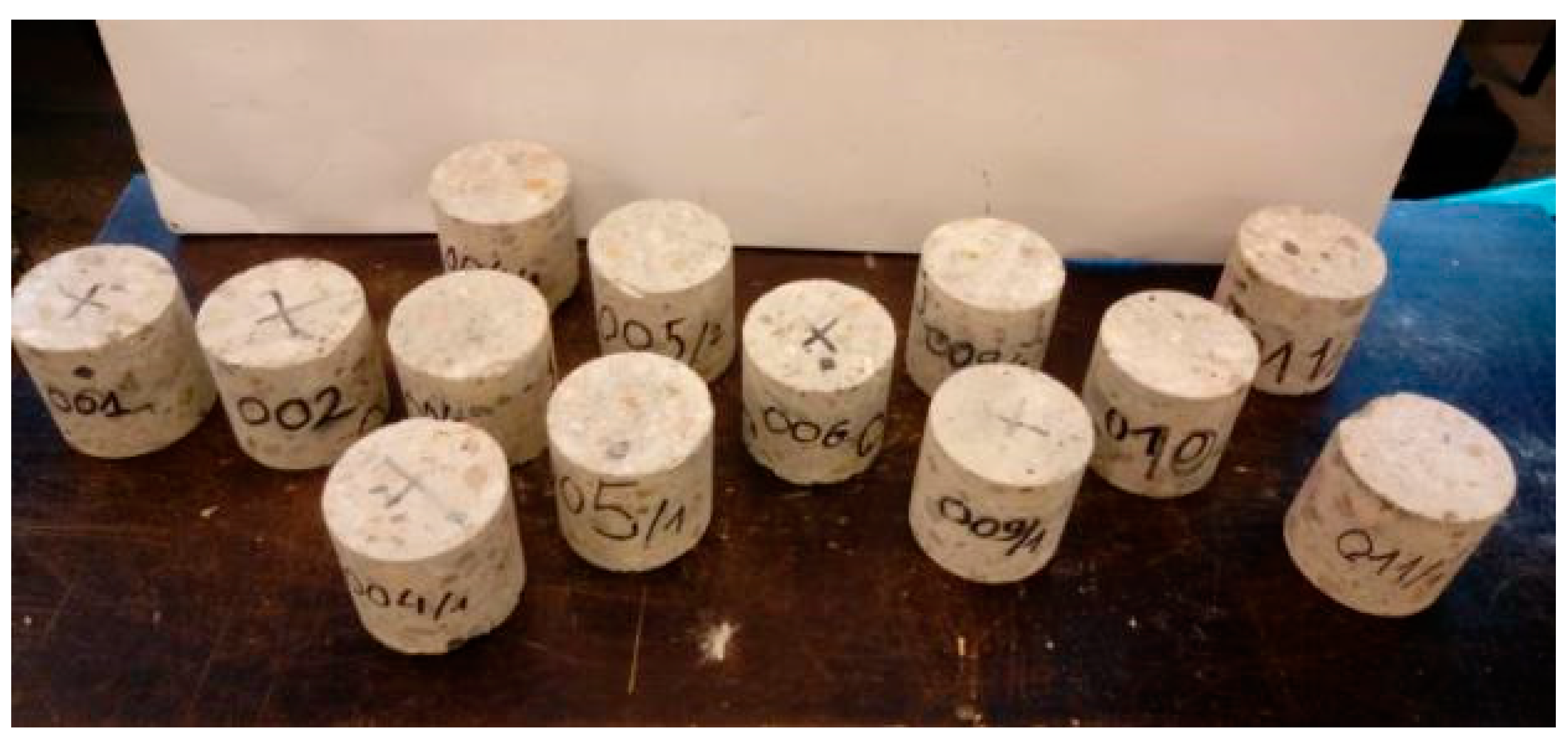
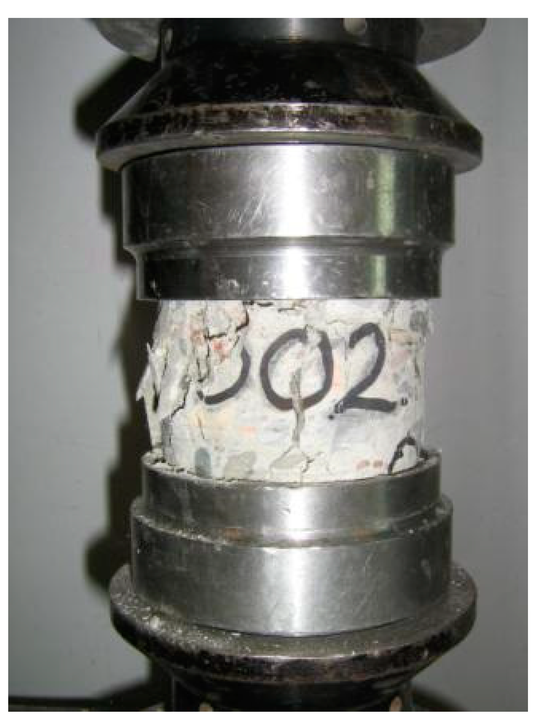
According to documents, concrete C25/30 and C30/37 were delivered to the construction site. After the fire, long concrete core samples (φ100 up to 350 mm) were taken from various structural elements as indicated in Table 2. Then some of these samples were split to prepare two or three new smaller samples (φ100/100 mm) to test the in-situ compressive strength fck,is (Figure 6 and Figure 7) according to [31].
The destructive tests proved that the strength of concrete at the depth of approximately 50 mm did not decrease. There were minor differences between results from the smaller samples among the long sample, as presented in Table 2 for the long samples no. 004, 005, 009, and 011. Therefore, top surface compressive strength was assessed with the non-destructive method, because that helped decide precisely on the slab cross-section unaffected depth.
3.2. UPV Model Calibration
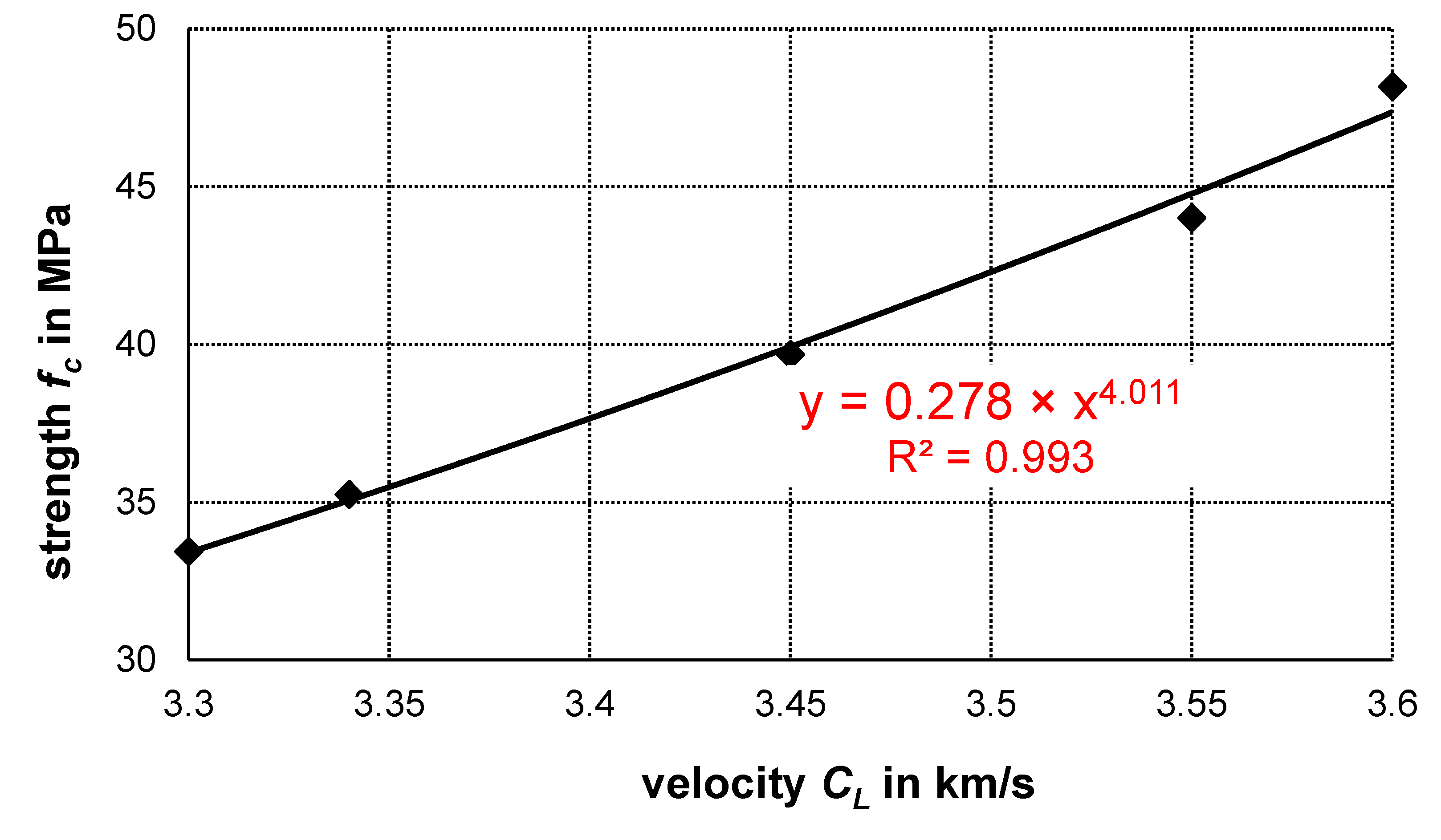
To determine the strength of concrete in the core samples, i.e., varying strength over the slab depth, the relationship fc = f (CL) between the tested ultrasonic wave velocity CL and the compressive strength of concrete fc was established on the samples that were subsequently destructed. That relationship is presented in Figure 8. Based on the regression analysis exponential function was found to fit the best to experimental results.
3.3. UPV Non-Destructive Tests
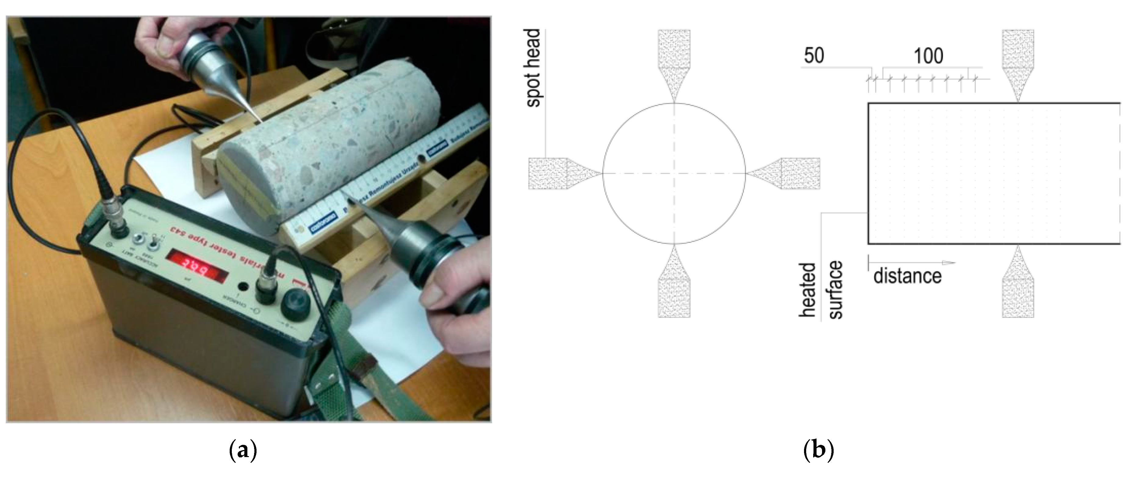
The tests were carried out with the Unipan 543 digital device and 40 kHz point ultrasonic heads (Figure 9a). They were performed on the samples no. 7, 8, and 11 (Table 2). With a simplification, each sample was exposed to unknown fire temperatures for an unknown period. After the humidity stabilized at the air-dry level, the samples were examined, and the heads were applied at distances of 5 mm from the top surface and every 10 mm in the subsequent measurement planes (Figure 9b). The ultrasonic wave velocity CL was determined as the mean for two measurements in two perpendicular directions.
4. Results
The results of the ultrasonic examination of the compressive strength over the thickness of the slab are presented in Figure 10, Figure 11 and Figure 12.
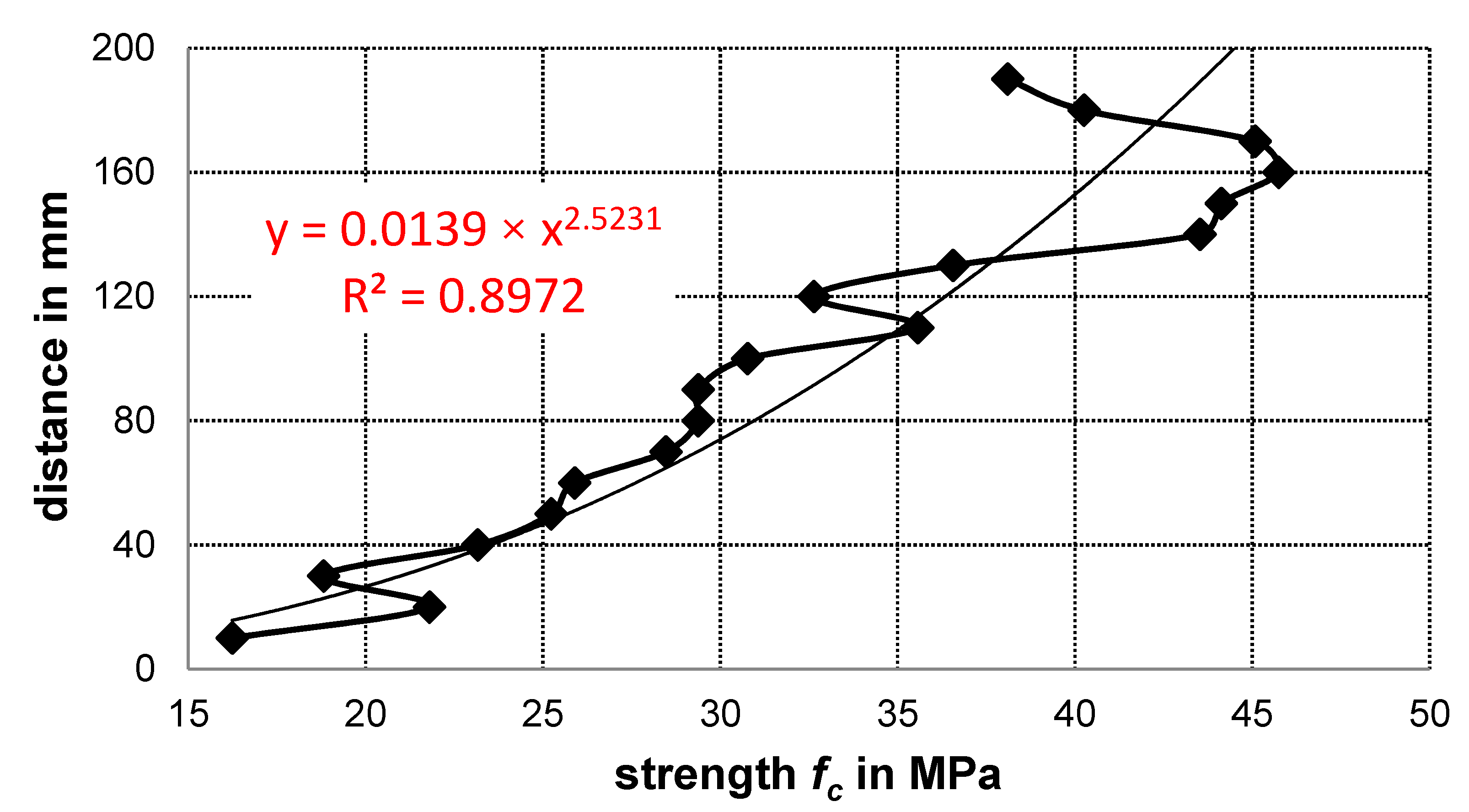
The strength close to the surface exposed to the fire in sample no. 008 is low 15.5 MPa (Figure 10) and then almost uniformly increases to 46.0 MPa in the layer 160 mm away from the top surface. However, the layers between 160 and 200 mm exhibit lower strength (37–46 MPa). A power function was found to best fit the results of that sample, as presented in Figure 10.
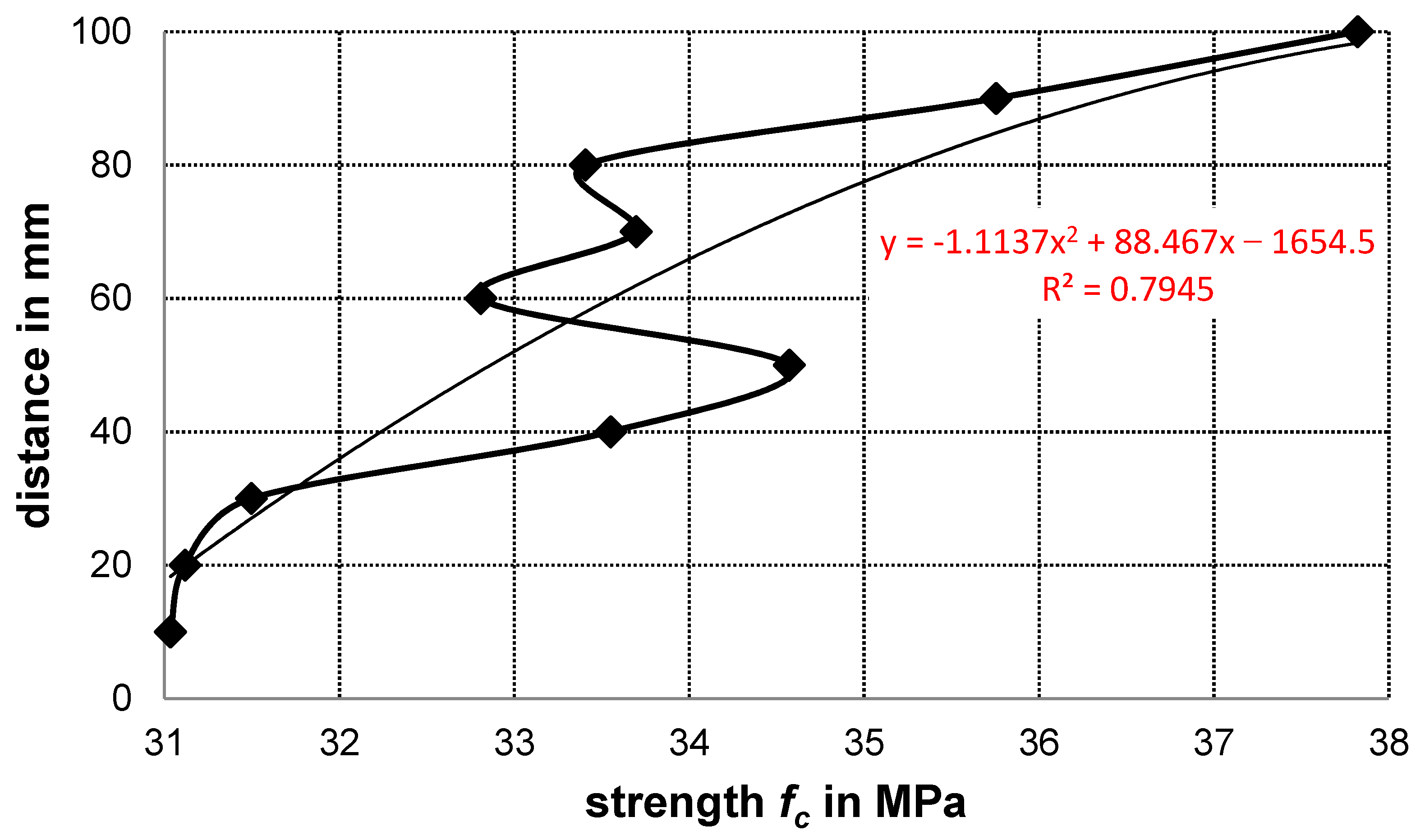
In the top zone, the results obtained from the sample no. 007 (Figure 11) loaded with fire for a short period, does not follow the strength distribution of the sample no. 008. In the 25–30 mm top zone the strength is significantly reduced to 33 MPa, while in the remaining part of the sample the strength reaches 38–43 MPa. The bottom 40 mm part of was not available because the sample was broken on the bottom reinforcement.
The tested sample no. 011/2 was not directly exposed to the fire and the strength reduction is small, i.e., 7 MPa–18% of 38 MPa (Figure 12). Therefore, the observed variation is considered as a natural effect associated with the porosity change in the conventional concrete [27,28].
Based on the regression analysis, second order polynomial was found to best fit the results in the sample not exposed to the fire.
5. Discussion
Results presented in [27,28] prove that in ordinary concretes of various strength and age the strength in the top layers is on average up to 50% smaller than in the bottom layers. Moreover, analysis of destructive tests demonstrates that the strength in the middle part of the sample (i.e., between ¼ and ¾ of the sample length) is only on average 25% smaller. That fact is also confirmed in the standard [31]. With this in mind, exceeding 50% reduction of the maximum strength can be considered as the fire effect. Smaller reductions can be attributed to the porosity or the fire, but the origin remains unknown.
Considering the outcomes of [27,28], the effect measured in the sample no. 008 (the top surface strength is only 33% of the maximum one) is the result of the fire. The strength of concrete in the middle of the core sample was 30 MPa and that represents the strength reduction of 25%. Thus, the influence of high temperature on concrete was found to be restricted to 30 ± 5 mm, because at that depth the strength reaches 23 MPa, i.e., 50% of its highest value. Using the results of the regression analysis 23 MPa are obtained at the depth of 38 mm.
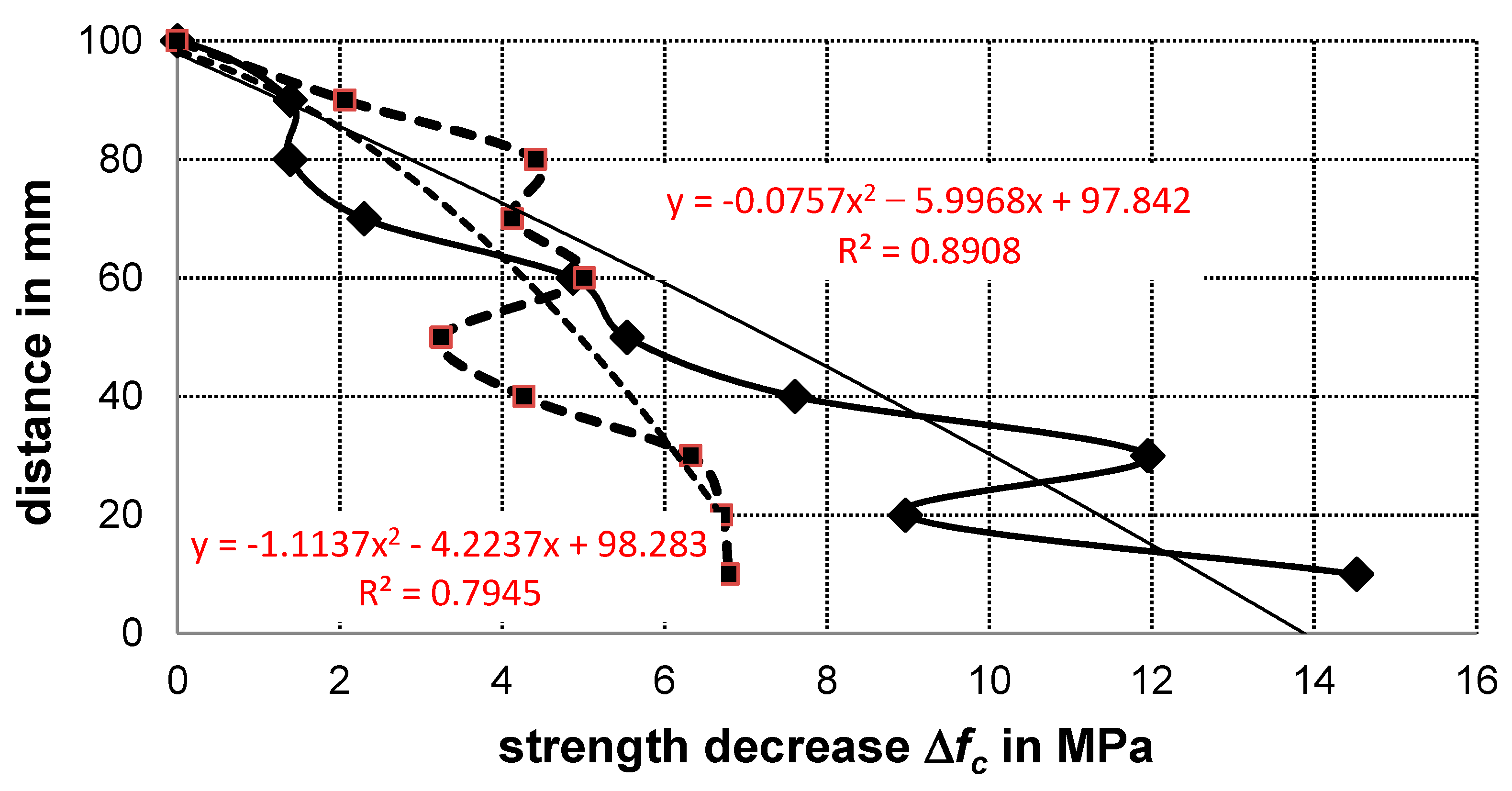
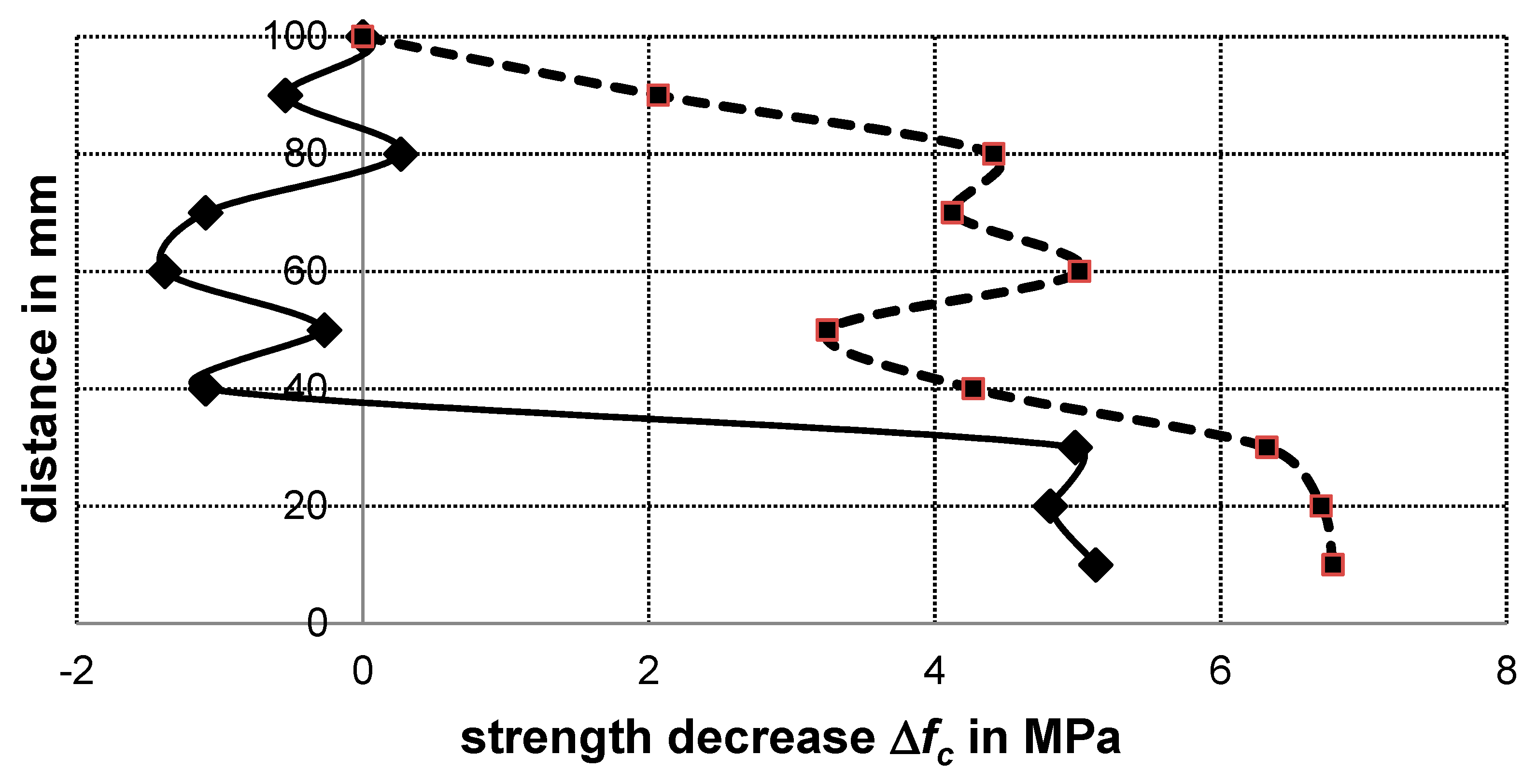
However, when the results of the unaffected sample (no. 011/2) are directly compared with the results of the sample no. 008, it appears that temperature influence reaches 60 mm as presented in Figure 13, because at that depth the strength decrease (Δfc = fc(depth = 100 mm) − fc(current depth)) in the sample no. 008 became greater than in the sample no. 011/2. If the regression functions are compared that depth reaches 85 mm. However, that result should be statistically verified.
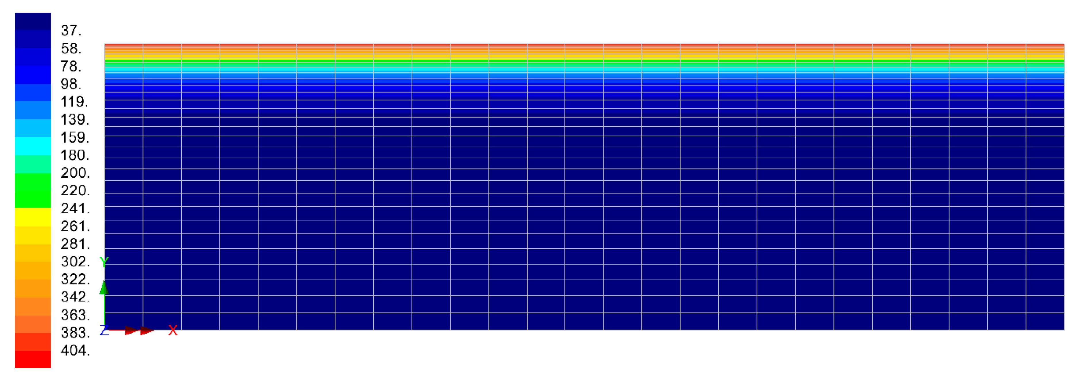
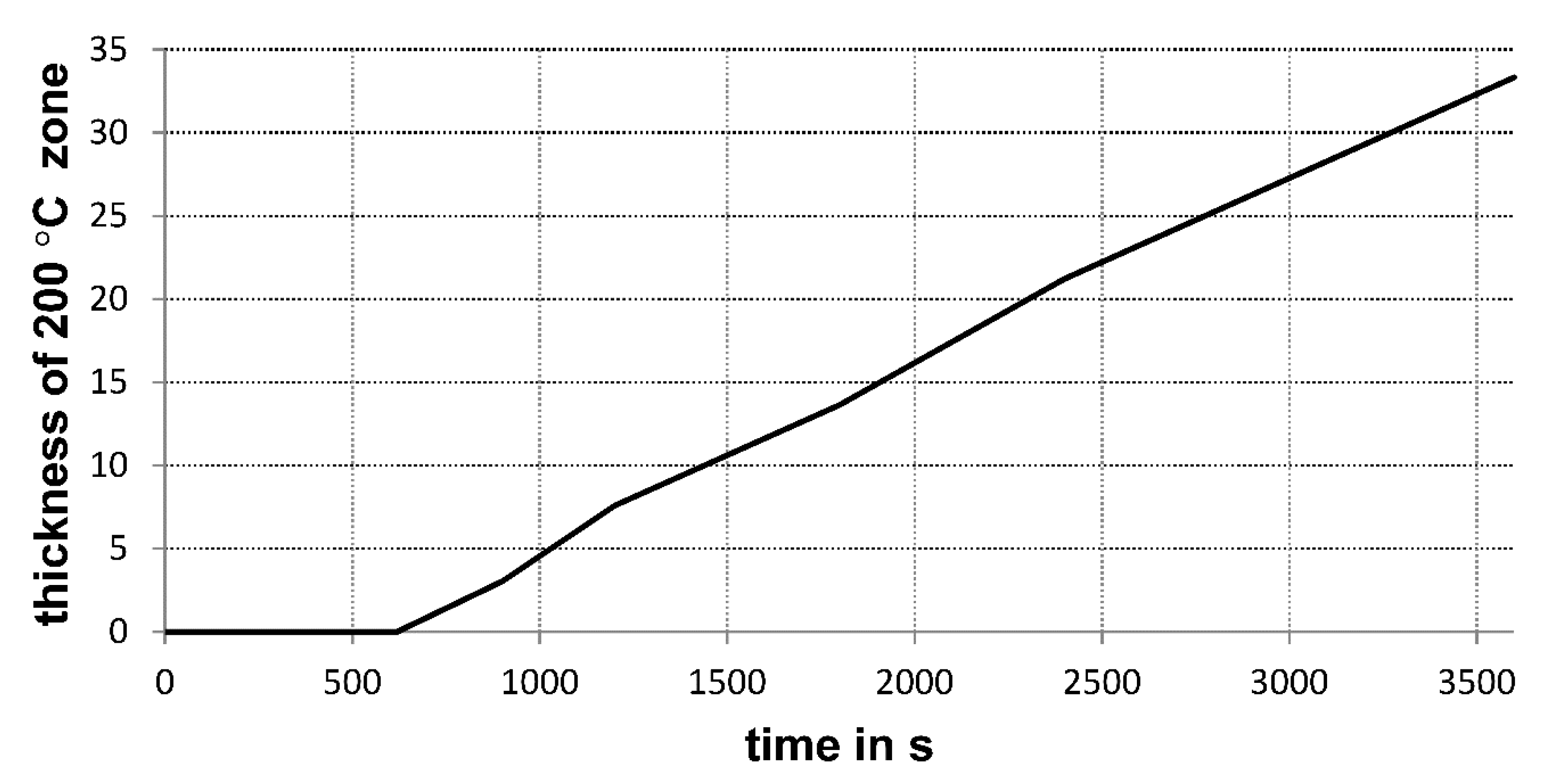
Assuming that the concrete compressive strength begins to descend at the temperature of 200 °C it is possible to estimate the time of fire exposure or concrete surface temperature. Therefore, if an external fire model according to [32] is considered, the time of fire exposure is not longer than 2400 s to 3600 s (with the maximum temperature of 680 °C). This time was estimated based on the transient temperature finite element analysis of the 300 mm thick concrete slab performed in the software [33]. An example of the results is presented in Figure 14. The temperature distribution plots were then used to assess the development of the zone where temperature excites 200 °C as presented in Figure 15.
The obtained strength decrease in the samples no. 007 and 011/2 are considered as natural effects because the decreases are only 25% and 18%. The abrupt strength change in the top layer of the sample no. 007 (in the distance of 25–30 mm in Figure 11) can be a result of smaller concrete density in that layer. Figure 16 supports that statement, because the decrease in sample no. 007 is even smaller than in the unaffected sample no. 011/2.
6. Conclusions
The presented ultrasound method helps decide on the actual strength of concrete at the depth of the fire exposed slab or other structural element, and can be important in the assessment of the compressed zone. The method can be more accurate by decreasing measurement distance and is sufficient in practice. The method can replace visual evaluation of concrete strength based on the concrete colour change. Moreover, from a practical perspective, the presented method is accurate enough because it is possible to estimate the thickness of the concrete layer necessary to be removed or reinforced. However, the procedure does not solve the problem where the samples should be taken and that requires further research. Concrete colour change should be considered as the first attempt to select the sample taking spots.
The results from non-destructive UPV tests are reliable, but only when strength reduction due to concrete placement direction and porosity are considered. They must be supported with destructive tests on the fire unaffected samples. Moreover, the porosity effects can be additionally checked with other non-destructive methods, such as computed tomography (CT) scanning, ultrasonic wave analysis, or destructive tests like X-ray diffraction (XRD) or scanning electron microscope (SEM).
Author Contributions
Conceptualization, R.W. and B.S.; methodology, R.W. and B.S.; validation, R.W. and B.S.; formal analysis, R.W.; investigation, R.W. and B.S.; resources, R.W. and B.S.; data curation, R.W. and B.S.; writing—original draft preparation, R.W. and B.S.; writing—review and editing, R.W.; visualization, R.W.; supervision, R.W.; project administration, R.W.; funding acquisition, R.W. and B.S. All authors have read and agreed to the published version of the manuscript.
Funding
This research received no external funding.
Acknowledgments
The authors would like to thank Ireneusz Pałęcki for his help in the preparation and documentation of the samples.
Conflicts of Interest
The authors declare no conflict of interest.
References
- Khoury, G.A. Effect of fire on concrete and concrete structures. Prog. Struct. Eng. Mater. 2000, 2, 429–447. [Google Scholar] [CrossRef]
- Ma, Q.; Guo, R.; Zhao, Z.; Lin, Z.; He, K. Mechanical properties of concrete at high temperature—A review. Constr. Build. Mater. 2015, 93, 371–383. [Google Scholar] [CrossRef]
- Arioz, O. Effects of elevated temperatures on properties of concrete. Fire Saf. J. 2007, 42, 516–522. [Google Scholar] [CrossRef]
- Hager, I. Colour Change in Heated Concrete. Fire Technol. 2014, 50, 945–958. [Google Scholar] [CrossRef] [Green Version]
- Wróblewski, R.; Gierczak, J.; Smardz, P.; Kmita, A. Fire and collapse modelling of a precast concrete hall. Struct. Infrastruct. Eng. 2016, 12, 714–729. [Google Scholar] [CrossRef]
- Szymanowski, J.; Sadowski, Ł. The influence of the addition of tetragonal crystalline titanium oxide nanoparticles on the adhesive and functional properties of layered cementitious composites. Compos. Struct. 2020, 233, 111636. [Google Scholar] [CrossRef]
- Krzywiński, K.; Sadowski, Ł.; Szymanowski, J.; Żak, A.; Piechówka-Mielnik, M. Attempts to Improve the Subsurface Properties of Horizontally-Formed Cementitious Composites Using Tin(II) Fluoride Nanoparticles. Coatings 2020, 10, 83. [Google Scholar] [CrossRef] [Green Version]
- Ervine, A. Damaged Reinforced Concrete Structures in Fire. Ph.D. Thesis, The University of Edinburgh, Edinburgh, UK, 2012. [Google Scholar]
- Fletcher, I.A.; Borg, A.; Hitchen, N.; Welch, S. Performance of Concrete in Fire: A Review of the State of the Art, with a Case Study of the Windsor Tower Fire. In Proceedings of the 4th International Workshop in Structures in Fire, Aveiro, Portugal, 10–12 May 2006; pp. 779–790. [Google Scholar]
- Neves, I.C.; Rodrigues, J.P.C.; Loureiro, A.D.P. Mechanical Properties of Reinforcing and Prestressing Steels after Heating. J. Mater. Civ. Eng. 1996, 8, 189–194. [Google Scholar] [CrossRef]
- Sahamitmongkol, R.; Choktaweekarn, P.; Sancharoen, P.; Tangtermsirikul, S. Damage analysis of an RC column subjected to long-term transient elevated temperature. Struct. Infrastruct. Eng. 2011, 7, 921–930. [Google Scholar] [CrossRef]
- Kodur, V. Properties of Concrete at Elevated Temperatures. ISRN Civ. Eng. 2014, 2014, 1–15. [Google Scholar] [CrossRef]
- Felicetti, R.; Gambarova, P.G.; Meda, A. Residual behavior of steel rebars and R/C sections after a fire. Constr. Build. Mater. 2009, 23, 3546–3555. [Google Scholar] [CrossRef]
- Cree, D.; Green, M.; Noumowé, A. Residual strength of concrete containing recycled materials after exposure to fire: A review. Constr. Build. Mater. 2013, 45, 208–223. [Google Scholar] [CrossRef]
- Poon, C.S.; Azhar, S.; Anson, M.; Wong, Y.L. Strength and durability recovery of fire-damaged concrete after post-fire-curing. Cem. Concr. Res. 2001, 31, 1307–1318. [Google Scholar] [CrossRef]
- Hsu, J.H.; Lin, C.S. Residual Bearing Capabilities of Fire-Exposed Reinforced Concrete Beams. Int. J. Appl. Sci. Eng. 2006, 4, 151–163. [Google Scholar]
- Kodur, V.K.R.; Raut, N.K.; Mao, X.Y.; Khaliq, W. Simplified approach for evaluating residual strength of fire-exposed reinforced concrete columns. Mater. Struct. Constr. 2013, 46, 2059–2075. [Google Scholar] [CrossRef]
- Biolzi, L.; Cattaneo, S.; Rosati, G. Evaluating residual properties of thermally damaged concrete. Cem. Concr. Compos. 2008, 30, 907–916. [Google Scholar] [CrossRef]
- Kirchhof, L.D.; Lorenzi, A.; Silva Filho, L.C.P. Assessment of Concrete Residual Strength at High Temperatures using Ultrasonic Pulse Velocity. e-J. Nondestruct. Test. 2015, 20, 1–10. [Google Scholar]
- Yang, H.; Lin, Y.; Hsiao, C.; Liu, J.Y. Evaluating residual compressive strength of concrete at elevated temperatures using ultrasonic pulse velocity. Fire Saf. J. 2009, 44, 121–130. [Google Scholar] [CrossRef]
- Hager, I. Methods for assessing the state of concrete in fire damaged structures | Metody oceny stanu betonu w konstrukcji po pożarze. Cem. Wapno Bet. 2009, 29, 167–178. [Google Scholar]
- Hager, I.; Tracz, T.; Krzemień, K. The usefulness of selected non-destructive and destructive methods in the assessment of concrete after fi re|Przydatność wybranych metod nieniszczących i niszczących w ocenie stanu betonu po pożarze. Cem. Wapno Bet. 2014, 2014, 145–151. [Google Scholar]
- Colombo, M.; Felicetti, R. New NDT techniques for the assessment of fire-damaged concrete structures. Fire Saf. J. 2007, 42, 461–472. [Google Scholar] [CrossRef]
- Grantham, M.; Mechtcherine, V.; Schneck, U.; Eden, M. Fire damaged concrete—The potential for on-going deterioration post-fire in concrete heated to temperatures of less than 300 °C. Comput. Vis. Med. Image Process. 2012, 2, 497–502. [Google Scholar]
- Stawiski, B. Attempt to estimate fire damage to concrete building structure. Arch. Civ. Mech. Eng. 2006, 6, 23–29. [Google Scholar] [CrossRef]
- Hawileh, R.A.; Kodur, V.K.R. Performance of reinforced concrete slabs under hydrocarbon fire exposure. Tunn. Undergr. Space Technol. 2018, 77, 177–187. [Google Scholar] [CrossRef]
- Stawiski, B. Ultradźwiękowe Badania Betonów i Zapraw Głowicami Punktowymi; Oficyna Wydawnicza Politechniki Wrocławskiej: Wrocław, Poland, 2009. [Google Scholar]
- Stawiski, B. The heterogeneity of mechanical properties of concrete in formed constructions horizontally. Arch. Civ. Mech. Eng. 2012, 12, 90–94. [Google Scholar] [CrossRef]
- Toubal Seghir, N.; Benaimeche, O.; Krzywiński, K.; Sadowski, Ł. Ultrasonic Evaluation of Cement-Based Building Materials Modified Using Marble Powder Sourced from Industrial Wastes. Buildings 2020, 10, 38. [Google Scholar] [CrossRef] [Green Version]
- EN 1992-1-2 Eurocode 2: Design of Concrete Structures—Part 1–2: General Rules—Structural Fire Design; Comité Européen de Normalisation: Brussels, Belgium, 2004.
- EN 13791: Assessment of Strength in Structures and Precast Concrete Components; Comité Européen de Normalisation: Brussels, Belgium, 2007.
- EN 1991-1-2 Eurocode 1. Actions on Structures. General Actions. Actions on Structures Exposed to Fire; Comité Européen de Normalisation: Brussels, Belgium, 2002.
- Lusas Solver Reference Manual; Lusas: Kingston upon Thames, UK, 2016.
Figure 1.
(a) Split and (b) cracking of concrete cover after firefighting.

Figure 2.
Concrete surfaces after fires: (a) top surface partially covered with watertight bituminous material, (b) vertical surface insulated with Styrofoam.
Figure 2.
Concrete surfaces after fires: (a) top surface partially covered with watertight bituminous material, (b) vertical surface insulated with Styrofoam.

Figure 3.
Concrete colour change after the fire. (a): concrete surface after cover splitting (b): colour change over the thickness based on a core sample.
Figure 3.
Concrete colour change after the fire. (a): concrete surface after cover splitting (b): colour change over the thickness based on a core sample.

Figure 4.
Diagram of the building damaged during the fire.

Figure 5.
Façades after the fire.

Figure 6.
Core samples prepared for the strength test (height 100 mm).

Figure 7.
Sample no. 002 during the strength test.

Figure 8.
Correlation of concrete compressive strength an ultrasonic wave velocity.

Figure 9.
(a) Ultrasound Pulse Velocity (UPV) measurements with Unipan 543 and 40 kHz spot heads; (b) the head positions during testing.
Figure 9.
(a) Ultrasound Pulse Velocity (UPV) measurements with Unipan 543 and 40 kHz spot heads; (b) the head positions during testing.

Figure 10.
Compressive strength distribution in the sample taken from the slab heavily loaded with the fire (sample no. 008).
Figure 10.
Compressive strength distribution in the sample taken from the slab heavily loaded with the fire (sample no. 008).

Figure 11.
Compressive strength distribution in the sample taken from the slab loaded with the fire for a short period (sample no. 007).
Figure 11.
Compressive strength distribution in the sample taken from the slab loaded with the fire for a short period (sample no. 007).

Figure 12.
Distribution of compressive strength of concrete in the sample not exposed to the fire (sample no. 011/2).
Figure 12.
Distribution of compressive strength of concrete in the sample not exposed to the fire (sample no. 011/2).

Figure 13.
Distribution of compressive strength decrease in the samples no. 008 (continuous line) and 011/2 (dashed line). (Δfc = fc(depth = 100 mm) − fc(current depth)).
Figure 13.
Distribution of compressive strength decrease in the samples no. 008 (continuous line) and 011/2 (dashed line). (Δfc = fc(depth = 100 mm) − fc(current depth)).

Figure 14.
Roof slab (300 mm thick). Temperature distribution at time 2400 s.

Figure 15.
Roof slab (300 mm thick). Time development of the zone where temperature excites 200 °C.

Figure 16.
Distribution of compressive strength decrease in the samples no. 007 (continuous line) and 011/2 (dashed line). (Δfc = fc(depth = 100 mm) − fc(current depth)).
Figure 16.
Distribution of compressive strength decrease in the samples no. 007 (continuous line) and 011/2 (dashed line). (Δfc = fc(depth = 100 mm) − fc(current depth)).


Table 1.
References and problems related to the paper scope.
| Problem | Reference |
|---|---|
| Material properties: concrete, steel. Reinforced concrete basic properties in elevated temperatures (spalling, bond, deformation, cracking) | [1,2,3,8,9,10,11,12,13,14,15] |
| Residual load bearing capacity of reinforced concrete elements | [13,16,17] |
| Residual strength of concrete based on furnace tests | [15,18,19,20,21,22,23] |
| Concrete residual strength tests based on non-destructive methods | [19,20,22,23] |
| Evaluation of post fire damage of concrete | [4,15,23,24,25] |
| Behaviour of reinforced concrete elements under hydrocarbon fire | [26] |
| Ultrasound Pulse Velocity (UPV) assessment of concrete and cement-based materials homogeneity | [25,27,28,29] |
Table 2.
Concrete compressive strength based on φ100/100 mm samples.
| Core Sample No. | Structural Element | Approximate Age at Testing in Days | Compressive Strength in MPa | Remarks |
|---|---|---|---|---|
| 001 | Ground floor, patio, north wall | 260 | 35.0 | |
| 002 | Ground floor, patio, south wall | 260 | 41.0 | |
| 003 | Slab over the garage with a crack | 300 | Not tested | |
| 004 | Slab over the garage | 300 | 42.5 | Test sample no. 004/1 exposed to fire |
| 40.9 | Test sample no. 004/2 | |||
| 48.4 | Test sample no. 004/3 | |||
| 005 | Slab over the garage | 300 | 39.9 | Test sample no. 005/1 exposed to fire |
| 39.7 | Test sample no. 005/2 | |||
| 006 | Balcony in patio, north wall, 2nd floor | 100 | 45.3 | |
| 007 | Slab of north roof | 110–125 | Not tested | |
| 008 | Slab of south roof | 110–125 | Not tested | |
| 009 | Slab of south roof | 110–125 | 48.2 | Test sample no. 009/1 exposed to fire |
| 44.0 | Test sample no. 009/2 | |||
| 010 | Slab of south roof | 110–125 | 48.4 | |
| 011 | Slab of north roof | 110–125 | 33.4 | Test sample no. 011/1 exposed to fire |
| 35.2 | Test sample no. 011/2 |
© 2020 by the authors. Licensee MDPI, Basel, Switzerland. This article is an open access article distributed under the terms and conditions of the Creative Commons Attribution (CC BY) license (http://creativecommons.org/licenses/by/4.0/).
Share and Cite
MDPI and ACS Style
Wróblewski, R.; Stawiski, B. Ultrasonic Assessment of the Concrete Residual Strength after a Real Fire Exposure. Buildings 2020, 10, 154. https://0-doi-org.brum.beds.ac.uk/10.3390/buildings10090154
AMA Style
Wróblewski R, Stawiski B. Ultrasonic Assessment of the Concrete Residual Strength after a Real Fire Exposure. Buildings. 2020; 10(9):154. https://0-doi-org.brum.beds.ac.uk/10.3390/buildings10090154
Chicago/Turabian StyleWróblewski, Roman, and Bohdan Stawiski. 2020. "Ultrasonic Assessment of the Concrete Residual Strength after a Real Fire Exposure" Buildings 10, no. 9: 154. https://0-doi-org.brum.beds.ac.uk/10.3390/buildings10090154
Note that from the first issue of 2016, this journal uses article numbers instead of page numbers. See further details here.