
Assessment of Selected Models for FRP-Retrofitted URM Walls under In-Plane Loads


1
Faculty of Civil Engineering and Architecture Osijek, Josip Juraj Strossmayer University of Osijek, Vladimira Preloga 3, 31000 Osijek, Croatia
2
Faculty of Civil Engineering Mostar, University of Mostar, Matice Hrvatske b.b., 88000 Mostar, Bosnia and Herzegovina
3
Faculty of Technical Sciences, University of Novi Sad, Trg Dositeja Obradovića 6, 21000 Novi Sad, Serbia
4
Faculty of Civil Engineering in Sarajevo, University of Sarajevo, Patriotske Lige 30, 71000 Sarajevo, Bosnia and Herzegovina
*
Authors to whom correspondence should be addressed.
Buildings 2021, 11(11), 559; https://0-doi-org.brum.beds.ac.uk/10.3390/buildings11110559
Submission received: 11 October 2021
/
Revised: 14 November 2021
/
Accepted: 16 November 2021
/
Published: 19 November 2021
(This article belongs to the Special Issue Retrofitting and Strengthening in Structural Elements of Historic Masonry Buildings)
Abstract
:One way to improve a structure’s total load-bearing capacity during an earthquake is to apply fiber-reinforced polymers (FRP) to unreinforced walls. The study discusses the use of FRP to strengthen unreinforced masonry (URM) structures. Although, many studies were conducted on the FRP strengthening of URM buildings, most of them were experiments to investigate the success of retrofitting approaches, rather than developing a successful design model. A database of 120 FRP-reinforced wall samples was created based on the current literature. Various approaches for calculating the bearing capacity of FRP-reinforced masonry are presented and detailed. The findings of the experiments, which were compiled into a database, were compared to those derived using formulas from the literature and/or building codes, and the model’s limitations are discussed.
1. Introduction
Masonry structures are among the most common type of constructions. According to Matthys and Noland [1], masonry buildings account for more than 70% of all residential buildings in the world, and practically all historic buildings are masonry. Masonry structures are distinguished by other important features such as different design options and aesthetics, solidity, strength, low-cost maintenance, good acoustic and thermal properties, fire resistance, and others, in addition to the simplicity of construction procedures and durability [2]. There are several disadvantages when it comes to the quality of masonry constructions in terms of building structural unreliability, high construction costs, low seismic resistance, etc. [3]. The reason for some of these disadvantages is that many masonry structures are located in earthquake-prone areas, where strong earthquakes reveal their flaws and defects, causing large damage and human casualties [4].
Most URM buildings are built to meet only some or no seismic-resistance standards [5,6,7]. As a result, a huge number of masonry structures lack the ability to dissipate seismic energy through inelastic deformation. The most typical causes of masonry damage include design and detail errors (e.g., inadequate masonry connection with reinforced concrete structural components), low-quality masonry units and/or mortar, errors in mortar component selection (e.g., large amounts of plasticizer), and poor masonry work performance [8,9].
Not only was no earthquake protection employed during the traditional construction of old buildings, but many of them also lacked maintenance and, if they were renovated at all, were in poor condition [10,11]. As a result, numerous earthquakes have recently caused considerable damage to historic masonry buildings. These damages demanded extensive repairs, which could have been avoided or mitigated in some way.
Masonry structures subjected to earthquakes can and do endure damage. Permanent deformations and displacements are caused by the dissociation of the links between the load-bearing parts. The weakest elements of the building collapse first, which might eventually lead to the entire structure being demolished [12]. To protect human life and material values in historic buildings, this scenario must be avoided. This includes the preservation of structural, architectural, and cultural qualities.
Improving a structure’s resilience to seismic impacts can improve the structure’s overall strength. This involves improving the structure’s ability to absorb inelastic deformation. This can be accomplished by modifying the structural system by transmitting energy through alternate loading modes, or by enhancing the ductility of the structural system’s constituent elements [13].
The existing earthquake resistance of the building, as well as its significance, type, and intended use, dictate the exact technique, scale, and scope of the strengthening works. The process of renewal and/or reinforcement should be streamlined to meet the principles of selectivity and graduality in prioritization, as well as the comprehensiveness of historical values and scientifically based interventions.
The increase in both the compressive strength and ductility of the masonry prisms once strengthened with CFRP was reported by Brencich and Gambarotta [14]. Lignola et al. [15], in their study, proposed a confinement model and compared it with the experimental results found in the literature. They concluded that the model was able to accurately predict the condition where the FRP is efficiently taken into account, regardless of the scale levels. However, for real-scale structures, the level of FRP efficiency was lower. During the last century, different researchers conducted various studies confirming the increase in ductility of FRP-strengthened masonry [16,17,18].
The increase in ductility and stiffness in the range from 15 to 30% was noted on the strengthened masonry wallets with CFRP compared to the un-strengthened samples, which were exposed to concentric and eccentric loading [19].
The following are some of the methods for reinforcing and/or restoring historic masonry structures [20]:
- -
- those that rebuild and/or reinforce the brickwork to improve the present masonry’s resistance (gluing, grouting, torking, prestressing, sheathing, complete replacement of the elements)
- -
- those that restore the resistance of the entire structure (adding new walls in a weak direction, fixers, joints)
- -
- those that enhance the spatial rigidity of the entire structure, i.e., prohibit movement perpendicular to the plane (interconnection of masonry and interconnection of masonry and ceiling tiles, reinforced concrete frames, prestressed steel frames).
Traditional or modern reinforcing techniques, as well as a combination of both, can be used to renovate and/or strengthen masonry buildings and heritage structures. There are many different types of both techniques, as well as differing perspectives on which techniques should be used, depending on the type of structure or damage. Zhuge [21], Španić et al. [22], and Hadzima-Nyarko et al. [23,24] provided comprehensive reviews and comparisons of various retrofitting procedures.
Modern composite polymer reinforcing techniques have become one of the principal reinforcement techniques for masonry buildings due to little or no additional weight, the greater tensile and shear strength of masonry, and rapid and non-invasive applications.
One way of improving a structure’s load-bearing capability during an earthquake is to apply FRP to unreinforced walls. Reinforcement and/or restoration techniques for old buildings necessitate the use of high-quality materials with mechanical attributes, such as strength and stiffness, which provide stability and durability, avoiding the need for repair. Some of the advantages of composite materials include light handling and transport, good fatigue properties, high tensile strength in the fiber direction, suitability for machining (tailoring), excellent corrosion resistance (insensitivity to corrosion), good dynamic loading behavior, and light weight. FRP, as with other structural materials, has limitations that raise questions about its suitability for structural strengthening, such as high cost, fragile behavior, UV degradation, and photodegradation (due to light exposure).
FRP strips (which are usually unidirectional) or FRP sheets (which are bidirectional) can also be tied to the surface of unreinforced walls to boost their shear strength. This method can prevent two types of fractures that are common in non-reinforced walls subjected to seismic loads. Depending on the direction of the earthquake pressures, these include in-plane fractures defined by bending or shear action, and out-of-plane fractures characterized by bending.
This paper presents a database of 120 FRP-reinforced wall samples based on the available literature. Several methods for determining the bearing capacity of FRP-reinforced masonry are presented and thoroughly examined. The experimental results are then compared to those obtained using formulas from the literature.
2. Failure Modes of Masonry Walls
In recent years, a large number of masonry structures were damaged by seismic action and, for that reason, were demolished. Most of the existing masonry buildings were built without the application of any seismic regulations because during their construction theses applications did not even exist. That is why many buildings cannot withstand strong ground motions.
Three types of mechanisms and failure modes of unreinforced masonry walls were detected once exposed to in-plane loads (Figure 1):
- (a)
- crushing the pressure area of the wall along the edge due to the action of bending moment and longitudinal force (flexural failure);
- (b)
- sliding on the mortar joint due to the action of transverse force (sliding shear failure);
- (c)
- creating a diagonal crack that connects the upper corner and the opposite lower corner in the direction of the imaginary pressure diagonal (diagonal cracking mode).
Which mechanics will be activated depends on the wall geometry (height/width ratio), quality of materials, the ratio of the compression shear stresses (σ/τ), and boundary restraints [25].
3. Modern Techniques for Strengthening Masonry Buildings
Due to their low, or negligible, additional weight, the increased tensile and shear strength of masonry, and quick and non-invasive applications, modern composite polymer reinforcing techniques are one of the primary reinforcement solutions for masonry constructions.
3.1. Reinforcement of Masonry Buildings Using Steel Strips
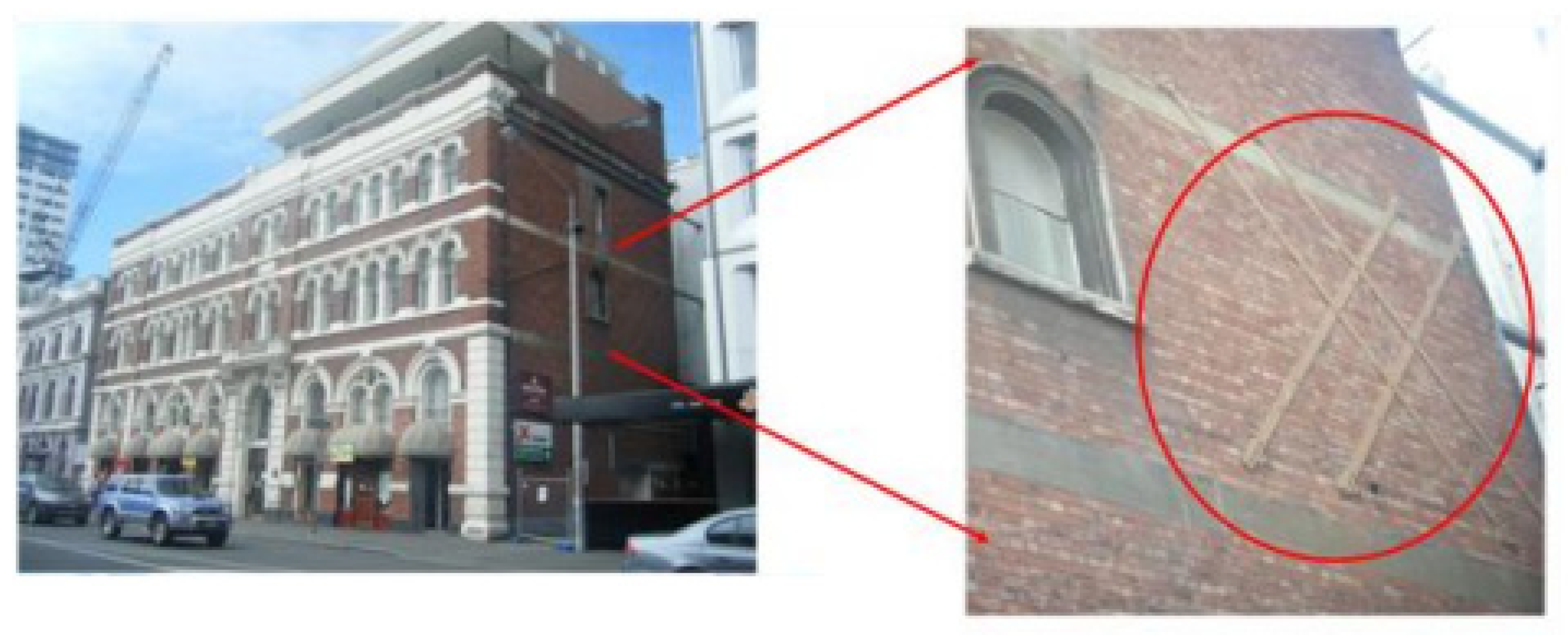
Reinforcement with steel strips and/or bars on the outside improves the lateral rigidity of the structure and allows the structural elements to work together. The use of steel diagonals (couplings) for cladding the masonry is shown in Figure 2. On such a reinforced building, cracks are still expected during the earthquake, but the masonry and steel reinforcing system remains efficient and sufficiently rigid. Additional reinforcements enable a robust energy dissipation system and good lateral displacement control [24].
Once the wall has cracked, diagonal stiffening is used to turn the structural element into an X-retained frame. If the primary load-bearing walls are damaged, the lateral load is absorbed by tensile stresses in one diagonal and one vertical sheet, as well as pressure in the wall at the opposite end.
The wall’s lateral in-plane resistance can be increased by 4.5 times when using diagonal and vertical bracing [27,28]. Crushing at the pressure area at the base wall causes the shear-bearing wall to fail. The ratio of the URM wall rigidity to the newly formed bracing is a significant factor impacting the steel reinforced system’s efficiency. This implies that the wall will have a large crack before the steel parts are activated [27]. For the particular specimens tested in [29], the steel strips improved the lateral strengths by a factor of 1.17 to 2.05 as compared to the reference specimen.
The steel elements’ ends must be secured (anchored) in a very robust and secure manner. Such strong connections are difficult to create since there are not enough strong parts of the surrounding wall to anchor the steel elements. This restriction may make it impossible to utilize this approach in some instances.
3.2. Reinforcements of Masonry Buildings Using Composite Materials
To reinforce historical heritage masonry buildings, many types of composite materials are used. FRPs are made up of at least two layers of tiny continuous fibers connected by a polymer matrix (epoxy resin, polyester, vinyl ester). Aramid (AFRP), carbon (CFRP) (Figure 3a), and glass (GFRP) fibers, as well as natural cellulose and agave fibers, are the most frequently utilized fibers. Composite fibers are carriers of strength (loads), while the matrix ensures a load distribution among the fibers and protects them from harmful environment and mechanical damage. The composition of the matrix, the size of the interlayer, and the orientation of the fibers all have an impact on efficiency, in addition to the material properties [24].
In a study [31], the authors emphasized the use of basalt fiber-reinforced polymer (BFRP), a new inorganic continuous fiber (Figure 3b). The modulus of elasticity and failure mode of BFRP and GFRP are effectively the same, as the stiffness and strength of basalt fibers are much closer to glass than to carbon. However, the modulus of elasticity of CFRP is about three times that of BFRP (and GFRP), and this might lead to the FRP-debonding [32]. Moreover, BFRP is much cheaper than CFRP [31].
FRP products can be thin-walled, in the form of ribbons, slats, sheets, and netting, or thick-walled, in the form of bars and slats with rectangular or circular cross-sections, depending on the application. FRP textiles, which are usually tenths of mm thick, may be easily placed and can significantly improve strength, stiffness, and ductility without adding significant mass. The fibers in the matrix can be continuous, discontinuous (short), orientated in one or two directions, or randomly dispersed.
FRP is 10 times stronger and 15 times lighter than steel, and 8 times stronger, 22 times stiffer, and 1.5 times lighter than aluminum [33]. As previously stated, these products have drawbacks such as a brittle failure behavior and substantial change in characteristics along and across the fiber direction. Their biggest disadvantage, however, is that they are not ductile (no material sag at a certain stress as in steel) [24].
FRP is ideal for reinforcement and repair because of its light weight and simplicity of application. FRP strips/sheets, which are a few millimeters thick, may be installed fast and boost strength, stiffness, and ductility without introducing a substantial mass. The activities involved in placing the strips/lamellas are as follows. First, a sander is used to clean and level the wall. Second, strong air pressure is used to remove dust and loose parts. After that, a thin layer of glue is placed on the wall’s surface where the lamellae will be bonded. The lamellas are then cut to size and set on the floor on plastic sheets before epoxy resin is poured onto them. The lamella is still pressed with the roller after it is physically fastened to the wall. Finally, a thin layer of epoxy resin is applied to the lamellae’s exterior surfaces.
Textile-reinforced mortar (investigated in [34]), hereafter abbreviated as TRM, and textile-reinforced concrete (TRC) (investigated in [35,36]), have been widely employed in Europe for the past 20 years, while they are known in the United States as fabric-reinforced cementitious matrix systems (FRCM). This method allows for a better compatibility of old and new materials, the removal of reinforcements, less building intervention, and long-term sustainability. These are crucial elements in the preservation of cultural and historical structures.
TRM was recently employed in historic buildings that were subjected to seismic activity, and it was not found to affect the original structure’s stiffness [37]. From an economic standpoint, using textiles with basalt fibers to reinforce stone walls is far more cost-effective than using polymers with carbon or aramid fibers. Basalt fibers have great mechanical qualities, a good adhesion, are non-toxic, have no environmental constraints, and contain no carcinogenic or poisonous elements such as asbestos [38].
This material has good fatigue resistance and better vapor permeability, higher tensile strength than fiberglass products, greater ultimate elongation at break than carbon-fiber products, and better resistance to chemical action and impact load [39]. Basalt fiber products have all of the above qualities, making them a viable choice for strengthening old stone buildings [40] or vaults composed of brick materials that are subjected to seismic activity [41].
In comparison to the unreinforced column specimen, columns reinforced with mortar-bonded basalt fibers have increased compressive strength [42]. The use of basalt fibers in textile wrapping improves the shear strength of masonry and prevents it from collapsing during large earthquakes. Basalt fiber textiles might be considered the material of the future for green and sustainable development due to their nature, qualities, and properties [43]. Strengthening with these materials satisfies the requirements for physical and chemical compatibility with existing materials, durability, reversibility, and minimal construction intervention.
3.3. Advantages and Disadvantages of Modern Reinforcement Techniques
Polymers reinforced with carbon fibers, in the form of flexible strips with a thickness of 0.1 to 0.4 mm, improve bending resistance perpendicular to the plane of the wall and shear resistance in the plane of the wall. Their advantages include good behavior under dynamic load and durability, high tensile strength in the direction of the strips, and easy wall surface adjustment, while their disadvantages include linear elastic behavior that results in failure and poor overall elongation.
Static strengthening and regeneration are aided by CFRP in the form of sheets (fabrics). Their advantages include good behavior under dynamic load and durability, high tensile strength in the direction of fibers, and easier adaptation to the wall surface, while their disadvantages include impermeability to moisture and air through the wall, and different tensile strength along and perpendicular to the direction of fibers [31].
CFRP in the form of rigid lamellae with a thickness of 1.2 to 1.5 mm increases the resistance to bending due to the action outside the plane of the wall and resistance to shear. Their advantages include an increase in load-bearing capacity of up to 80%, and their disadvantages include the problems of anchoring the lamellae at the nodes and the ends, as well as a sudden yielding under long-term stress close to strength. CFRP in the form of bars improves bending and shear resistance. Their advantages include no mechanical damage and no environmental influence on the fibers in the rod, while their disadvantages include anchoring issues and abrupt yielding under continuous stress near the expected strength. CFRP in the form of meshes increases the structural ductility and energy dissipation ability. Their advantage is that they protect the building from being partially or completely demolished. The quality of the plaster determines their resistance to ultraviolet radiation and efficiency, which is a disadvantage [44].
Lamellae made from AFRP connect structural parts whose behavior depends on the relative displacement speed. Their advantages include increased final shear strength, resistance to alkaline chemical compounds, water resistance, good reversibility, and low thermal and electrical conductivity, but their main disadvantage is moisture and air imperviousness through the wall.
The success of the maintenance and renovation of buildings depends on understanding the dynamic behavior of the structure and considering the historical features and cultural values of the building. These principles should be kept in mind when deciding between traditional or modern reinforcement techniques. The qualities of the materials that can be used, the availability and suitability of procedures and technologies, as well as the required degree of building resilience, must all be considered when selecting strengthening approaches. Increasing a building’s resistance can be achieved by increasing the masonry’s mechanical qualities and/or fixing flaws in the structure’s overall behavior.
To prevent additional damage and extend the building’s durability, selected techniques and materials must ensure mechanical and structural compatibility with the original structural behavior, as well as physical and chemical compatibility with existing materials. Maintaining, reinforcing, and restoring masonry structures increases their longevity and worth.
Traditional techniques frequently fail to provide sufficient protection to the maximum projected earthquakes and may result in culturally unacceptable alterations to the original construction form. Strengthening with these procedures can be complicated, resulting in the loss of building usage and higher financial expenditures, and in other circumstances, they are not even practicable. As a result, in recent years, techniques that meet criteria such as minimal intervention, durability, compatibility, interchangeability, or reversibility have become increasingly popular.
Due to low or negligible added weight, fast and non-invasive application, and increasing tensile and shear strength of masonry, modern reinforcement techniques using polymeric materials have become the dominant strengthening procedures for masonry buildings of architectural heritage.
Compliance with the methodology of safety assessment and selection of the correct and most effective strengthening technique that best meets the requirements of a particular building, in terms of its original construction and architectural/historical value, is at the heart of the problem of maintenance, strengthening, and preservation of masonry buildings in architectural heritage.
4. Models for Reinforcing URM Walls with FRP under the Influence of Shear in the Plane
For masonry reinforced with externally bonded FRP, various models were developed. They assume that shear strength is equal to the sum of two terms [21]:
where:
- —shear strength of URM walls.
- —the effect of FRP on increasing the shear strength of masonry.
can be calculated using the provisions of the existing design standards for each country. This means that the main differences between each available model are attributed to the contribution of the fiber-reinforced polymers VFRP.
Many factors influence the strength of VFRP, including FRP strength, orientation, anchoring length, modulus of elasticity, and the strain distribution of FRP, which has the greatest impact. As a result, the precise modeling of FRP contribution to shear strength is impossible [45].
During the experimental campaigns, it was found that FRP did not reach its tensile strength at failure due to premature detachment [21].
Various models (Triantafillou [45], Triantafillou and Antonoupoulos [46], Nanni and Tumialan [47], Wang et al. [48], Garbin et al. [49] Marcari et al. [17]) based on the effective strain or truss analogies, as well as guidelines and regulations, were created in different countries over the last two decades. These include, for example: Chinese standard [50], Italian standard CNR DT 200 [51], AC 125 model [52], ACI 440.7R-10 [53], etc.
4.1. Triantafillou (1998)
Only narrow-strap FRP laminates are expected to be used in the application of the model proposed by Triantafillou [45].
The effect of shear reinforcement can be calculated using the following formula:
where:
- —partial safety factor for FRP in uniaxial tension 1.15, 1.2, and 1.25 for carbon, aramid, and glass FRPs (hereinafter abbreviated as CFRP, AFRP, and GFRP, respectively); however, this safety factor was not used to validate the model with experimental results;
- —wall length;
- —wall thickness.
Factor 0.7 is used only when calculating earthquake effects.
The formula for the effective FRP strain, , is based on experimental data gathered on concrete samples and reads as follows:
where:
- —effective FRP strain;
- —FRP area fraction in the horizontal direction;
- —modulus of elasticity of FRP;
- —FRP axial rigidity.
4.2. Chinese Standards (2006)
Strengthening schemes with various orientations (horizontal, diagonal, and mixed scheme with the horizontal and diagonal combined) are included in the Chinese standard [50]. The FRP’s contribution is computed using the following formula:
where:
- —FRP participation coefficient;
- —Young’s modulus of elasticity of FRP;
- —design value for effective stress of FRP;
- —cross-sectional area of the i-th FRP shear reinforcement;
- —the angle of the i-th strip of the FRP;
- n—total number of transverse reinforcements.
4.3. AC 125 Model (2007)
The AC 125 model [52] provides formulas for rectangular cross-section walls with fibers placed on one or both sides. When FRP is attached on both sides of the wall (on all four sides) at an angle θ to the vertical axis of the element, the shear strength is calculated as follows:
where:
- —thickness of the FRP;
- —wall height;
- —fiber orientation;
- —tensile strength of the composite material (MPa):
This equation does not apply to stone walls because fully wrapped FRP was not used for masonry.
If the FRP is applied to only one side at an angle higher than 75° to the corresponding axis, the increase in nominal shear strength is calculated as follows:
Equation (13) applies only to walls strengthened with continuous FRP sheets [21].
The effective stress is determined as a constant value of 0.0015 (FRP attached on one side) and 0.004 (FRP attached on all sides). The proposed constant values are debatable since effective stress is a function of axial rigidity (), and is an FRP area fraction in the horizontal direction.
4.4. Garbin et al.’s Model (Garbin et al., 2007)
Garbin et al. [49] derived the equations for the calculation of the shear strength of FRP. In the case of FRP strips, the equation for shear strength according to Garbin et al.’s model is:
where:
- —effective stress in the FRP is 0.5 of the ultimate strength;
- —cross-sectional area;
- —effective design strength;
- —actual depth of masonry in direction of shear considered;
- —spacing of reinforcement.
Effective design strength is obtained from Equation (10):
where:
- —strengthening systems factors (0.65 for most cases);
- —environment reduction factor;
- —tensile strength of the FRP.
In the case of FRP laminates, the equation for shear strength according to Garbin et al.’s model is:
where is a coefficient used to consider the orientation of fibers concerning the direction of the failure surface of the wall.
4.5. ACI 440.7R-10 (2010)
According to the ACI guidelines, the contribution of FRP reinforcement in the case of the shear-controlled fracture defines the reduction coefficient of the bond , which was moderate based on experimental data from many researchers. The ACI guidelines apply to the walls strengthened horizontally and vertically by FRP.
The contribution of FRP sheets, where Pfv is the total force that the FRP system may input into the wall, can be calculated as follows [53]:
where :
where:
- —height of the panel;
- —length of the panel;
- —center- to mid-interval FRP reinforcement measured perpendicular to the shear force direction;
- —cross-sectional area of the FRP reinforcement;
- —effective stress in the FRP.
Effective stresses are a function of effective strains, the Kv function, and the ultimate fracture strain of the FRP specified by the manufacturer:
The bond reduction coefficient for shear-controlled failure modes Kv depends on the FRP reinforcement index and is given by expressions depending on the FRP reinforcement index values.
5. Experimental Database
To evaluate the precision of the proposed models, it is necessary to compare the results from numerous experimental studies to the numerical model estimates. This has been carried out for concrete beams strengthened with FRP [54,55], while for masonry, the first researcher to carry out such a comparison was Zhuge [21].
Although the behavior of URM under shear strength is far more complex than that under bending, only a limited amount of research was conducted in this area.
The collected database consists of 120 different types of samples (Table 1). The results are based on the average value of the tested wall samples reinforced with glass FRP (GFRP), aramid FRP (AFRP), and polyvinyl alcohol (PVAFRP), as shown in Table 1. The database covers different types of fractures, including sliding on the joint, diagonal shear, bending, torsion of the FRP, and penetration through the walls. The database also includes the most common FRP masonry strengthening procedures discussed in the paper, which include FRP strips in various configurations. General material properties of the FRP-reinforced masonry testing samples included in the database are presented in Table 2.
Because the shear strength of FRP was not included in any of the experiments, the contribution of FRP to the shear strength of the reinforced masonry was calculated by subtracting the contribution of URM from the overall shear strength of the reinforced masonry. The actual properties of the materials from the experiments were taken into account while estimating the contribution of FRP using each calculation model, and partial safety factors were removed from all equations.
When FRP strips were applied vertically, they served as dowels, and the shear strength of the wall is enhanced, according to the testing findings. If they were arranged vertically, however, all of the selected design models anticipated that the FRP contribution would be zero.
5.1. Description of the Reinforced Wall Database
ElGawady et al. [16,56,57] carried out the tests described in their three papers, the first of which was published in 2005 [16], the second in 2006 [56], and the third in 2007 [57]. The testing of various masonry samples sized 70 cm × 160 cm × 7.5 cm, reinforced with FRP, was described in a report published in 2005, of which two testing samples were included in the database of this paper. A GFRP with a tensile strength of 2400 MPa and a modulus of elasticity of 70 GPa was used to strengthen one of these two samples, while an AFRP with a tensile strength of 2880 MPa and a modulus of elasticity of 100 GPa was used to strengthen the other. El Gawadi et al. [56] presented a report in 2006 that described pressure tests on wall samples at 4.8 MPa. This report contains the results of four tests. GFRP and AFRP plates were used to reinforce the testing samples. The tensile strength of GFRP was 2400 MPa, and the modulus of elasticity was 70 GPa, while the tensile strength of AFRP was 2880 MPa, and the modulus of elasticity was 100 GPa. The same mechanical features used in El Gawadi et al. [56] were also used in a paper published in 2007 [57].
Wang et al. [48] described the tests of nine samples with a compressive strength of 10.15 MPa. This study’s database included eight out of nine samples that were strengthened with GFRP. Horizontal, diagonal, and a combination of horizontal and vertical GFRP strips were used to reinforce the samples. The tensile strength of the GFRP strips used to reinforce the specimens was 1507 MPa, with a modulus of elasticity of 93.75 GPa and a reinforcement ratio of 0.056 percent.
Konthesingha et al. [58] tested 16 samples with a compressive strength of 14.2 MPa and dimensions of 120 cm × 120 cm × 11 cm. Two samples were considered as reference samples and 14 samples were reinforced with CFRP strips. The tensile strength of CFRP strips is 2484.6 MPa and the modulus of elasticity is 207.05 GPa. Figure 4 shows CFRP retrofitting schemes in this paper.
Zhang et al. [59] tested two different samples reinforced with FRP, one with a compressive strength of 2.46 MPa and the other with a compressive strength of 2.56 MPa. Samples were reinforced with BFRP and are part of this paper’s database. The tensile strength of BFRP strips was 1350 MPa and the modulus of elasticity was 96 GPa. Figure 5 shows the configurations of these specimens.
Santa-Maria and Alcaino [30] tested eight masonry samples. Four of them were reinforced with CFRP horizontal strips, and the remaining four samples were reinforced with CFRP diagonal strips. Figure 6 shows reinforced masonry patterns measuring 197.5 cm × 240 cm × 14 cm. CFRP strips that reinforce masonry samples have a tensile strength of 560 MPa and a modulus of elasticity of 250 MPa.
Zhou et al. [31] performed tests on masonry samples measuring 210 × 150 × 24 cm with a compressive strength of 3.73 MPa, reinforced with a BFRP tensile strength 2303 MPa and modulus of elasticity 105 GPa (Figure 7). BFRP can effectively increase the ultimate shear strength and drift in the ranges of 44–61%, 203–265%, respectively. Within the strengthening limit, the increase in the shear capacity of the strengthened specimens is proportional to the amount of FRP reinforcement.
Jarc-Simonič et al. [60] conducted tests in the laboratory and later in the field. New brick walls were used as test specimens. The researchers tested samples reinforced with diagonally laid FRP strips oriented in the direction of maximum tensile stresses, with horizontal FRP strips, or with a mix of vertical and horizontal FRP strips. Field experiments were undertaken on two old buildings, one in Maribor and the other in the village of Cirkovce. The dimensions of the walls tested in the field in Maribor were 200 cm × 100 cm × 30 cm and 200 cm × 100 cm × 45 cm, the dimensions of the walls tested in the village of Cirkovce were 210 cm × 100 cm × 52 cm, and the dimensions of the wall samples tested in the laboratory were 126 cm × 103 cm × 12 cm. The compressive strength of the walls tested in Maribor was 1.92 MPa, the compressive strength of the walls in Cirkovce was 1.45 MPa, and the compressive strength of the samples tested in the laboratory was 12.4 MPa.

Table 1.
General information on the experimental FRP-reinforced masonry samples included in the database.
Table 1.
General information on the experimental FRP-reinforced masonry samples included in the database.
| Author(s) | Reference | Year | Type | Configuration | Number of Specimens |
|---|---|---|---|---|---|
| Chuang et al. | [61] | 2003 | FRP | diagonal/mixed strips | 2 |
| Stratford et al. | [62] | 2004 | GFRP | sheet | 1 |
| El Gawadi et al. | [16] | 2005 | GFRP/AFRP | Diagonal stris/sheet | 4 |
| El Gawadi et al. | [56] | 2006 | GFRP/AFRP | sheet | 4 |
| Santa-Maria et al. | [63] | 2006 | CFRP | diagonal/horizontal strips | 4 |
| Wang et al. | [48] | 2006 | GFRP | horizontal/diagonal/mixed strips | 8 |
| El Gawady et al. | [57] | 2007 | GFRP/AFRP | sheet | 4 |
| Santa-Maria and Alcaino | [30] | 2011 | CFRP | Horizontal/diagonal strips | 8 |
| Farooq et al. | [64] | 2012 | CFRP | diagonal strips | 1 |
| Zhou et al. | [31] | 2013 | BFRP | mixed strips | 7 |
| Konthesingha et al. | [58] | 2013 | CFRP | vertical/horizontal strips | 14 |
| Bishcof et al. | [65] | 2014 | CFRP | vertical/mixed strips | 4 |
| Jarc Simonič et al. | [59] | 2014 | CFRP/GFRP | diagonal/horizontal/mixed/grid strips | 8 |
| Konthesingha et al. | [66] | 2015 | CFRP | Horizontal/vertical/grid strips | 18 |
| Martinelli et al. | [67] | 2016 | CFRP | diagonal/horizontal/vertical/grid strips | 8 |
| Pavan et al. | [68] | 2016 | GFRP/CFRP | horizontal strips/sheet | 7 |
| Rahman et al. | [69] | 2016 | PET FRP/CFRP | Diagonal/grid strips/sheet | 10 |
| Zhang et al. | [60] | 2017 | BFRP | mixed strips | 2 |
| Vega and Torres | [70] | 2018 | CFRP | mixed/diagonal strips | 6 |
Table 2.
General material properties of the FRP-reinforced masonry testing samples included in the database.
Table 2.
General material properties of the FRP-reinforced masonry testing samples included in the database.
| Parameter | Min | Max | Average | |
|---|---|---|---|---|
| Geometrical properties of the walls | Height (mm) | 225 | 2400 | 1227.07 |
| Length (mm) | 245 | 2470 | 1448.54 | |
| Thickness (mm) | 75 | 520 | 155.35 | |
| Compressive strength (MPa) | 1.45 | 30 | 13.06 | |
| Mechanical properties of the walls | Reinforcement ratio (%) | 0 * | 1.20 | 0.11 |
| Tensile strength (MPa) | 110 | 4830 | 2429.20 | |
| Elastic modulus (GPa) | 10 | 250 | 158.35 | |
| Shear strength—experimental (kN) | 16.5 | 456 | 161.04 | |
| Calculated shear strength as per selected models | Shear strength—Triantafillou model (kN) | 0 * | 537.02 | 106.00 |
| Shear strength—AC 125 model (kN) | 0 * | 1660.55 | 281.75 | |
| Shear strength—Garbin et al.’s model (kN) | 0 * | 4662.23 | 298.93 | |
| Shear strength—ACI 440.7R-10 (kN) | 0 * | 1687.68 | 168.63 | |
| Shear strength—Chinese standards (kN) | 0 * | 261.86 | 27.53 |
* for the specimens which have only vertical FRP strips.
5.2. Experimental Results vs. Values Estimated Theoretically
This section contains the comparison of the data obtained through experimental tests to the values estimated theoretically using the model proposed by Triantafillou [45]—see Equation (2), the Chinese standards model [50]—see Equation (4), the AC 125 model [52]—see Equation (5), the Garbin et al. model [49]—see Equation (9), and the ACI 440.7R-10 model [53]—see Equation (12). For each sample in the database, we compared the experimentally obtained FRP contribution to the shear strength to the FRP contributions computed by using the two models. The results are shown in Figure 8. Figure 8 shows the experimental-to-theoretical FRP contribution ratios versus the shear strengths of FRP-reinforced samples computed by different models. If the mentioned ratio is smaller than 1, the numerical result can be considered as “not on the safe side” because it overestimates the real shear strength capacity of the FRP-strengthened masonry element. On the other hand, all experimental-to-theoretical FRP contribution ratios larger than 1 indicate that these are conservative estimates that underestimate the shear strengths of the FRP-strengthened elements.
According to Triantafillou’s model [45], the experimental-to-theoretical FRP contribution ratio of less than 1 is obtained for 70% samples, between 1 to 2 for ~18% of the samples, and larger than 2 for 12% of the samples. The largest experimental-to-theoretical FRP contribution ratios are obtained for the tested samples in Vega and Torres [70], with the largest ratio of 8.80 obtained for the tested sample “D-SL-C”.
Furthermore, according to the AC 125 model [52], for 66% of the tested samples, the experimental-to-theoretical FRP contribution ratio is less than 1, for 6% of the samples, it is between 1 and 2, and for 28% of the samples, it is larger than 2. The largest experimental-to-theoretical FRP contribution ratios are obtained for the models tested by Konthesingha et al. [58], with the largest ratio of 10.33 obtained for the sample B1-2.
The largest experimental-to-theoretical FRP contribution ratios are obtained by the Garbin et al. model [49]. This model leads to ratios of less than 1 for 46% of the tested samples, between 1 and 2 for 22% of the samples, and larger than 2 for 32% of the tested samples. The largest experimental-to-theoretical FRP contribution ratio of 39.51 is obtained for the sample lab HV in Jarc Simonič et al. [59].
The ACI 440.7R-10 model [53] and the AC 125 model [52] produce similar results. For 66% of the tested samples, the ACI 440.7R-10 model [53] produces the experimental-to-theoretical FRP contribution ratio less than 1, for 14% of the samples, the contribution ratio is between 1 and 2, and for 20% of the samples, it is larger than 2. However, contrary to the AC 125 model [52], the largest experimental-to-theoretical FRP contribution ratio of 14.30 is obtained for the sample lab HV in Jarc Simonič et al. [59].
Finally, according to the Chinese standards model [50], even 92% of the tested samples have an experimental-to-theoretical FRP contribution ratio less than 1; for only 3% of the samples, it is between 1 and 2; and for 5% of the samples, it is larger than 2. Similar to Triantafillou’s model [45], the largest experimental-to-theoretical FRP contribution ratios are obtained for the tested samples in Vega and Torres [70], with the largest ratio of 3.26 obtained for the tested sample “D-SL-C”.
The mean values and standard deviations of the experimental-to-theoretical FRP contribution ratios are shown in Table 3. The results shown in Figure 8 and Table 3 indicate that, on average, the Triantafillou’s model [45] is the most accurate for the analyzed 120 samples as the average experimental-to-theoretical FRP contribution ratio is closest to 1.
Table 3.
Average experimental-to-theoretical FRP contribution ratios for the analyzed samples.
| Experimental-to-Theoretical FRP Contribution Ratio | |||
|---|---|---|---|
| Model | Number of Samples | Average | Standard Deviation |
| Triantafillou [45] | 120 | 1.0727 | 1.4926 |
| AC 125 [52] | 120 | 1.9954 | 2.7654 |
| Garbin et al. [49] | 120 | 2.7585 | 5.3612 |
| ACI 440.7R-10 [53] | 120 | 1.3975 | 2.1210 |
| Chinese standards [50] | 120 | 0.3047 | 0.6686 |
6. Conclusions
Fiber-reinforced polymers are one of the modern masonry reinforcement materials. This paper presents a series of methods for determining the load-bearing capacity of FRP-reinforced masonry. An extensive literature review of the experimental testing of FRP-strengthened masonry was conducted and a database of 120 samples was compiled. Five different theoretical models were selected to estimate the load-bearing capacity (shear strengths) and contributions of FRPs for the masonry 120 samples in the database. These are the models of Triantafillou [45], AC 125 [52], Garbin et al. [49], ACI 440.7R-10 [53], and Chinese standards [50].
We calculated the means and standard deviations of the experimental-to-theoretical FRP contribution ratios for five different theoretical models and 120 masonry samples (Table 3). These values, as well as the obtained comparison graph (Figure 8), indicate that the theoretical FRP contribution ratios obtained by Triantafillou’s model [45] are the closest to the experimental results, with the mean experimental-to-theoretical FRP contribution ratio equal to 1.07. The second best experimental-to-theoretical ratios for the FRP contribution are obtained for the ACI 440.7R-10 model [53], with a mean value of 1.40. These results, i.e., the mean experimental-to-theoretical FRP contribution ratios larger than 1, indicate that, on average, these models lead to lower values of the shear strengths of the strengthened masonry elements. Even more conservative theoretical estimates are obtained by using the AC 125 [52] and Garbin et al. [49] models, with the mean experimental-to-theoretical FRP contribution ratios of 2.00 and 2.76, respectively. On the other hand, the Chinese standards [50] appear to overestimate the effects of FRP on the shear strength of masonry samples, as the mean experimental-to-theoretical FRP contribution ratio for this model is 0.30 with even 92% of the tested samples having the experimental-to-theoretical FRP contribution ratio less than 1.
The presented results should be considered as a first step in comparing the selected theoretical models. In order to give some kind of recommendations and general conclusions, it is necessary to expand the database with more similar experimental samples, which are tested under similar conditions.
Author Contributions
Conceptualization, M.H.-N.; methodology, M.H.-N., S.Č., B.Đ.B. and N.A.; validation, M.H.-N., S.Č., B.Đ.B. and N.A.; formal analysis, S.Č. and B.Đ.B.; investigation, M.H.-N., S.Č., B.Đ.B. and N.A.; data curation, S.Č.; writing—original draft preparation, M.H.-N., S.Č., B.Đ.B. and N.A.; writing—review and editing, M.H.-N., B.Đ.B. and N.A.; supervision, M.H.-N. All authors have read and agreed to the published version of the manuscript.
Funding
This research received no external funding.
Conflicts of Interest
The authors declare no conflict of interest.
References
- Matthys, H.; Noland, L. Strengthening and retrofitting masonry buildings. In Proceedings of the An International Seminar on Evaluation, Strengthening and Retrofitting Masonry Buildings, TMS, Boulder, CO, USA, 11–18 October 1989. [Google Scholar]
- dos Santos, F.A.; Carvalho, M.C.R.; Roman, H.R. Architectural conception and design in structural masonry: Some practices to improve constructability. Int. J. Hous. Sci. 2009, 33, 57–67. [Google Scholar]
- Işik, M.F.; Işik, E.; Harirchian, E. Application of IOS/Android rapid evaluation of post-earthquake damages in masonry buildings. Gazi Mühendislik Bilimleri Derg. 2021, 7, 36–50. [Google Scholar]
- Bilgin, H.; Huta, E. Earthquake performance assessment of low and mid-rise buildings: Emphasis on URM buildings in Albania. Earthq. Struct. 2018, 14, 599–614. [Google Scholar]
- Hysenlliu, M.; Bidaj, A.; Bilgin, H. Influence of material properties on the seismic response of masonry buildings. Res. Eng. Struct. Mater. 2020, 6, 425–437. [Google Scholar] [CrossRef] [Green Version]
- Pavić, G.; Hadzima-Nyarko, M.; Bulajić, B.; Jurković, Ž. Development of seismic vulnerability and exposure models—A case study of Croatia. Sustainability 2020, 12, 973. [Google Scholar] [CrossRef] [Green Version]
- Pavić, G.; Hadzima-Nyarko, M.; Bulajić, B. A contribution to a UHS-based seismic risk assessment in Croatia—A case study for the city of Osijek. Sustainability 2020, 12, 1796. [Google Scholar] [CrossRef] [Green Version]
- Shkodrani, N.; Bilgin, H.; Hysenlliu, M. Influence of interventions on the seismic performance of URM buildings designed according to pre-modern codes. Res. Eng. Struct. Mat. 2021, 7, 315–330. [Google Scholar] [CrossRef]
- Tabrizikahou, A.; Hadzima-Nyarko, M.; Kuczma, M.; Lozančić, S. Application of shape memory alloys in retrofitting of masonry and heritage structures based on their vulnerability revealed in the Bam 2003 earthquake. Materials 2021, 14, 4480. [Google Scholar] [CrossRef] [PubMed]
- Hoła, A.; Sadowski, L.; Szymanowski, J. Non-destructive testing and analysis of a XIX-century brick masonry building. Arch. Civ. Eng. 2020, 66, 201–219. [Google Scholar]
- Hadzima-Nyarko, M.; Pavić, G.; Bulajić, B.; Plaščak, I. Seismic vulnerability assessment of small rural areas in Eastern Croatia. In Proceedings of the 17th World Conference on Earthquake Engineering, Sendai, Japan, 27 September–2 October 2021; Meguro, K., Ed.; Japan Association on Earthquake Engineering JAEE: Tokyo, Japan, 2021; pp. 1–12. [Google Scholar]
- Miranda, E.; Brzev, S.; Bijelić, N.; Arbanas, Ž.; Bartolac, M.; Jagodnik, V.; Lazarević, D.; Arbanas, S.M.; Zlatović, S.; Acosta, A.; et al. PRJ-2959/StEER-EERI: Petrinja, Croatia December 29, 2020, Mw 6.4 Earthquake—Field Research, Joint Reconnaissance Report; Kijewski-Correa, T., Ed.; DesignSafe: Oakland, CA, USA, 2021; p. 206. Available online: https://www.designsafe-ci.org/data/browser/public/designsafe.storage.published/PRJ-2959/#details-541797621822058005-242ac118-0001-012 (accessed on 9 August 2021).
- Churilov, S.; Dumova-Jovanoska, E. In-plane shear behavior of unreinforced masonry walls. In Proceedings of the 14th ECEE 2010 Ohrid Conference, Ohrid, Macedonia, 30 August–3 September 2010. [Google Scholar]
- Brencich, A.; Gambarotta, L. Mechanical response of solid clay brickwork under eccentric loading. Part II: CFRP reinforced masonry. Mater. Struct. 2005, 38, 267–273. [Google Scholar] [CrossRef]
- Lignola, G.P.; Angiuli, R.; Prota, A.; Aiello, M.A. FRP confinement of masonry: Analytical modeling. Mater. Struct. 2014, 47, 2101–2115. [Google Scholar] [CrossRef]
- ElGawady, M.; Lestuzzi, P.; Badoux, M. Aseismic retrofitting of unreinforced masonry walls using FRP. Compos. Part B 2005, 37, 148–162. [Google Scholar] [CrossRef]
- Marcari, G.; Manfredi, G.; Prota, A.; Pecce, M. In-plane shear performance of masonry panels strengthened with FRP. Compos. Part B 2007, 38, 887–901. [Google Scholar] [CrossRef]
- Maljaee, H.; Ghiassi, B.; Lourenço, P.B.; Oliveira, D.V. Moisture-induced degradation of interfacial bond in FRP-strengthened masonry. Compos. Part B Eng. 2016, 87, 47–58. [Google Scholar] [CrossRef] [Green Version]
- Thamboo, J.; Navaratnam, S.; Poologanathan, K.; Corradi, M. Characteristics of CFRP strengthened masonry wallets under concentric and eccentric compression. Case Stud. Constr. Mater. 2021, 14, e00472. [Google Scholar] [CrossRef]
- Tomaževič, M. Protupotresna obnova postojećih zidanih građevina. Građevinar 2000, 52, 683–693. [Google Scholar]
- Zhuge, Y. FRP-retrofitted URM walls under in-plane shear: Review and assessment of available models. J. Compos. Constr. 2010, 14, 743–753. [Google Scholar] [CrossRef]
- Španić, M.; Hadzima-Nyarko, M.; Morić, D. Strengthening of historical buildings with composite Polymers. Elec J. Fac. Civ. Eng. E-GFOS 2012, 5, 74–85. [Google Scholar]
- Hadzima-Nyarko, M.; Ademovic, N.; Pavić, G.; Šipoš, T.K. Strengthening techniques for masonry structures of cultural heritage according to recent Croatian provisions. Earthq. Struct. 2018, 15, 473–485. [Google Scholar]
- Hadzima-Nyarko, M.; Ademović, N.; Jeleč, M. Strengthening of Masonry Buildings-Methods and Examples; Faculty of Civil Engineering and Architecture Osijek: Osijek, Croatia, 2020. (In Croatian) [Google Scholar]
- Tomaževič, M. Earthquake-Resistant Design of Masonry Buildings; Elnashai, A.S., Dowling, P.J., Eds.; Imperial College Press: London, UK, 2000; p. 268. [Google Scholar]
- Dhakal, R.P. Performance of unreinforced masonry buildings in Canterbury earthquakes. In Proceedings of the 6th International Conference on Seismology and Earthquake Engineering, Tehran, Iran, 15 May 2011. [Google Scholar]
- ElGawady, M.; Lestuzzi, P.; Badoux, M. A review of conventional seismic retrofitting techniques for URM. In Proceedings of the 13th International Brick and Block Masonry Conference, Amsterdam, The Netherlands, 4–7 July 2004. [Google Scholar]
- Taghdi, M. Seismic Retrofit of Low-Rise Masonry and Concrete Walls by Steel Strips. Ph.D. Thesis, Department of Civil Engineering, University of Ottawa, Ottawa, ON, Canada, 2000. [Google Scholar]
- Farooq, H.; ElGawady, M.; Ilyas, M. Seismic in-plane performance of retrofitted masonry walls. KSCE J. Civ. Eng. 2014, 18, 226–237. [Google Scholar] [CrossRef]
- Santa-Maria, H.; Alcaino, P. Repair of in-plane shear damaged masonry walls with external FRP. Constr. Build. Mater. 2010, 25, 1172–1180. [Google Scholar] [CrossRef]
- Zhou, D.; Lei, Z.; Wang, J. In-plane behavior of seismically damaged masonry walls repaired with external BFRP. Compos. Struct. 2013, 102, 9–19. [Google Scholar] [CrossRef]
- Chen, Z.F.; Wan, L.L.; Lee, S.; Ng, M.; Tang, J.M.; Liu, M.; Lee, L. Evaluation of CFRP, GFRP and BFRP material systems for the strengthening of RC slabs. J. Reinf. Plast. Compos. 2008, 27, 1233–1243. [Google Scholar] [CrossRef]
- Čaušević, A.; Rustempašić, N. Rekonstrukcije Zidanih Objekata Visokogradnje; University of Sarajevu—Faculty of Architecture: Sarajevo, Bosnia, 2004. (In Bosnian) [Google Scholar]
- Triantafillou, T.C.; Papanicolaou, C.G.; Zisimopoulos, P.; Laourdekis, T. Concrete confinement with textile reinforced mortar (TRM) jackets. ACI Struct. J. 2006, 103, 28–37. [Google Scholar]
- Curbach, M.; Jesse, F. High-performance textile-reinforced concrete. Struct. Eng. Int. 1999, 4, 289–291. [Google Scholar] [CrossRef]
- Brameshuber, W.; Brockmann, J.; Roessler, G. Textile Reinforced Concrete for Formwork Elements‒Investigations of Structural Behaviour. FRPRCS-5 Fiber Reinforced Plastics for Reinforced Concrete Structures; Burgoyne, C.J., Ed.; Thomas Telford: London, UK, 2001; Volume 2, pp. 1019–1026. [Google Scholar]
- Corradi, M.; Osofero, A.I.; Borri, A.; Castori, G. Strengthening of historic masonry structures with composite materials. In Handbook of Research on Seismic Assessment and Rehabilitation of Historic Structures; IGI Global: Hershey, PA, USA, 2015; Volume 2, pp. 257–292. [Google Scholar]
- Kogan, F.M.; Nikitina, O.V. Solubility of chrysotile asbestos and basalt fibers in relation to their fibrogenic and carcinogenic action. In Proceedings of the Workshop on Biopersistence of Respirable Synthetic Fibers and Minerals Held, Lyon, France, 7–9 September 1992. [Google Scholar]
- Sim, J.; Park, C.; Young, M.D. Characteristics of basalt fiber as a strengthening material for concrete structures. Compos. Part B 2005, 36, 504–512. [Google Scholar] [CrossRef]
- García, D. Experimental and Numerical Analysis of Stone Masonry Walls Strengthened with Advanced Composite Materials. Ph.D. Thesis, Escuela de Ingeniería de Bilbao, Bilbao, Spain, 2009. [Google Scholar]
- Giamundo, V.; Lignola, G.P.; Maddaloni, G.; da Porto, F.; Prota, A.; Manfredi, G. Shaking table tests on a full-scale unreinforced and IMG retrofitted clay brick masonry barrel vault. Bull. Earthq. Eng. 2016, 14, 1663–1693. [Google Scholar] [CrossRef]
- Yilmaz, I.A.; Mezrea, P.E.; Ispir, M.; Binbir, E.; Bal, I.E.; Ilki, A. External confinement of brick masonry columns with open-grid basalt reinforced mortar. In Proceedings of the 4th Asia-Pacific Conference on FRP in Structures (APFIS 2013), International Institute for FRP in Construction, Melbourne, Australia, 11–13 December 2013. [Google Scholar]
- Di Ruocco, G. Basalt fibers: The green material of the XXI-century, for a sustainable restoration of historical buildings, Vitruvio. Int. J. Archit. Technol. Sustain. 2016, 2, 25–39. [Google Scholar] [CrossRef] [Green Version]
- Shrestha, H.; Pradhan, S.; Guragain, R. Experiences on Retrofitting of Low Strength Masonry Buildings by Different Retrofitting Technique in Nepal. In Proceedings of 15th World Conference on Earthquake Engineering, Lisbon, Portugal, 24–28 September 2012. [Google Scholar]
- Triantafillou, T.C. Strengthening of masonry structures using epoxy-bonded FRP laminates. J. Compos. Constr. 1998, 2, 96–104. [Google Scholar] [CrossRef]
- Triantafillou, T.C.; Antonopoulos, C. Design of concrete flexural members strengthened in shear with FRP. J. Compos. Constr. 2000, 4, 198–205. [Google Scholar] [CrossRef]
- Nanni, A.; Tumialan, J. Fiber-reinforced composites for the strengthening of masonry structures. Struct. Eng. Int. 2003, 134, 272–278. [Google Scholar] [CrossRef]
- Wang, Q.; Chai, Z.; Huang, Y.; Zhang, Y. Seismic shear capacity of brick masonry wall reinforced by GFRP. Asian J. Civ. Eng. 2006, 76, 563–580. [Google Scholar]
- Garbin, E.; Galati, N.; Nanni, A.; Modena, C.; Valluzzi, M. Provisional design guidelines for the strengthening of masonry structures subject to in-plane loading. In Proceedings of the 10th North American Masonry Conference, St. Louis, MO, USA, 3–5 June 2007; pp. 440–453. [Google Scholar]
- Chinese Standards. Design Guidance for FRP Strengthened Structures (Provisional); Ministry of Construction: Beijing, China, 2006. [Google Scholar]
- National Research Council. Guide for the Design and Construction of Externally Bonded FRP Systems for Strengthening Existing Structures; CNR-DT 200; National Research Council: Rome, Italy, 2004. [Google Scholar]
- AC125. Acceptance Criteria for Concrete and Reinforced and Unreinforced Masonry Strengthening Using Externally Bonded Fiber-Reinforced Polymer (FRP) Composite System; ICC Evaluation Service, Inc.: Brea, CA, USA, 2007. [Google Scholar]
- ACI 440.7R-10. Guide for the Design and Construction of Externally Bonded Fiber-Reinforced Polymer Systems for Strengthening Unreinforced Masonry Structures; American Concrete Institute Committee 440: Farmington Hills, MI, USA, 2010. [Google Scholar]
- Smith, S.T.; Teng, J.G. FRP-strengthened RC beams. II: Assessment of debonding strength models. Eng. Struct. 2002, 24, 397–417. [Google Scholar] [CrossRef]
- Pham, H.; Al-Mahaidi, R. Assessment of available prediction models for the strength of FRP retrofitted RC beams. Compos. Struct. 2004, 66, 601–610. [Google Scholar] [CrossRef]
- ElGawady, M.; Lestuzzi, P.; Badoux, M. Shear strength of URM walls retrofitted using FRP. Eng. Struct. 2006, 28, 1658–1670. [Google Scholar] [CrossRef]
- ElGawady, M.; Lestuzzi, P.; Badoux, M. Static cyclic response of masonry walls retrofitted with fiber-reinforced polymers. J. Compos. Constr. 2007, 111, 50–61. [Google Scholar] [CrossRef]
- Konthesingha, K.M.C.; Masia, M.J.; Petersen, R.B.; Mojsilovic, N.; Simundic, G.; Page, A.W. Static cyclic in-plane shear response of damaged masonry walls retrofitted with NSM FRP strips–An experimental evaluation. Eng. Struct. 2013, 50, 126–136. [Google Scholar] [CrossRef]
- Zhang, S.; Yang, D.; Sheng, Y.; Garrity, S.W.; Xu, L. Numerical modelling of FRP-reinforced masonry walls under in-plane seismic loading. Constr. Build. Mater. 2017, 134, 649–663. [Google Scholar] [CrossRef]
- Simonič, M.J.; Gostič, S.; Bosiljkov, V.; Žarnić, R. Testing and analysis of walls strengthened with FRP. Građevinar 2014, 66, 533–548. [Google Scholar]
- Chuang, S.W.; Zhuge, Y.; Wong, T.Y.; Peters, L. Seismic retrofitting of unreinforced masonry walls by FRP strips. In Proceedings of the 2003 Pacific Conference on Earthquake Engineering, Christchurch, New Zealand, 13–15 February 2003; Available online: http://db.nzsee.org.nz/2003/View/Paper012s.pdf (accessed on 10 November 2021).
- Stratford, T.; Pascale, G.; Manfroni, O.; Bonfiglioli, B. Shear strengthening masonry panels with sheet glass-fibre reinforced polymer. J. Compos. Constr. 2005, 8, 434–443. [Google Scholar] [CrossRef] [Green Version]
- Santa-Maria, H.; Alcaino, P.; Luders, C. Experimental response of masonry walls externally reinforced with carbon fiber fabrics. In Proceedings of the 8th U.S. National Conference on Earthquake Engineering, San Francisco, CA, USA, 18–22 April 2006. [Google Scholar]
- Farooq, S.H.; Ilyas, M.; Amir, S. Response of masonry walls strengthened with CFRP and steel strips. Arab. J. Sci. Eng. 2012, 37, 545–559. [Google Scholar] [CrossRef]
- Bischof, P.; Suter, R.; Chatzi, E.; Lestuzzi, P. On the use of CFRP sheets for the seismic retrofitting of masonry walls and the influence of mechanical anchorage. Polymers 2014, 6, 1972–1998. [Google Scholar] [CrossRef] [Green Version]
- Konthesingha, K.M.C.; Masia, M.J.; Petersen, R.B.; Page, A.W. Experimental evaluation of static cyclic in-plane shear behavior of unreinforced masonry walls strengthened with NSM FRP strips. J. Compos. Constr. 2015, 19, 04014055. [Google Scholar] [CrossRef]
- Martinelli, E.; Perri, F.; Sguazzo, C.; Faella, C. Cyclic shear-compression tests on masonry walls strengthened with alternative configurations of CFRP strips. Bull. Earthq. Eng. 2016, 14, 1695–1720. [Google Scholar] [CrossRef]
- Pavan, G.S.; Nanjunda Rao, K.S. Behavior of brick–Mortar interfaces in FRP-strengthened masonry assemblages under normal loading and shear loading. J. Mater. Civ. Eng. 2016, 28, 04015120. [Google Scholar] [CrossRef]
- Rahman, A.; Ueda, T. In-plane shear performance of masonry walls after strengthening by two different FRPs. J. Compos. Constr. 2016, 20, 04016019. [Google Scholar] [CrossRef] [Green Version]
- Vega, C.; Torres, N. External strengthening of unreinforced masonry walls with polymers reinforced with carbon fiber (Reforzamiento externo de muros de mampostería no reforzada mediante polímeros reforzados con fibra de carbono). IngenIería E InvestIgacIón 2018, 38, 15–23. [Google Scholar] [CrossRef]
Figure 1.
Type of failure modes: (a) rocking, (b) bed-joint sliding, (c) shear failure [24].
Figure 1.
Type of failure modes: (a) rocking, (b) bed-joint sliding, (c) shear failure [24].

Figure 2.
URM building retrofitted using bolted cross steel plates [26]. Reproduced with permission from R. P. Dhakal, Performance of Unreinforced Masonry Buildings in Canterbury Earthquakes; published by the International Institute of Earthquake Engineering and Seismology, 2011.
Figure 2.
URM building retrofitted using bolted cross steel plates [26]. Reproduced with permission from R. P. Dhakal, Performance of Unreinforced Masonry Buildings in Canterbury Earthquakes; published by the International Institute of Earthquake Engineering and Seismology, 2011.

Figure 3.
Specimens strengthened by: (a) CFRP strips [30]. Reproduced with permission from Santa-Maria, H., Alcaino, P. Repair of in-plane shear damaged masonry walls with external FRP; published by Elsevier, Construction and Building Materials, 2010. (b) BFRP stripes [31]. Reproduced with permission from Zhou, D.; Lei, Z.; Wang, J. In-plane behavior of seismically damaged masonry walls repaired with external BFRP; published by Elsevier, Composite Structures, 2013.

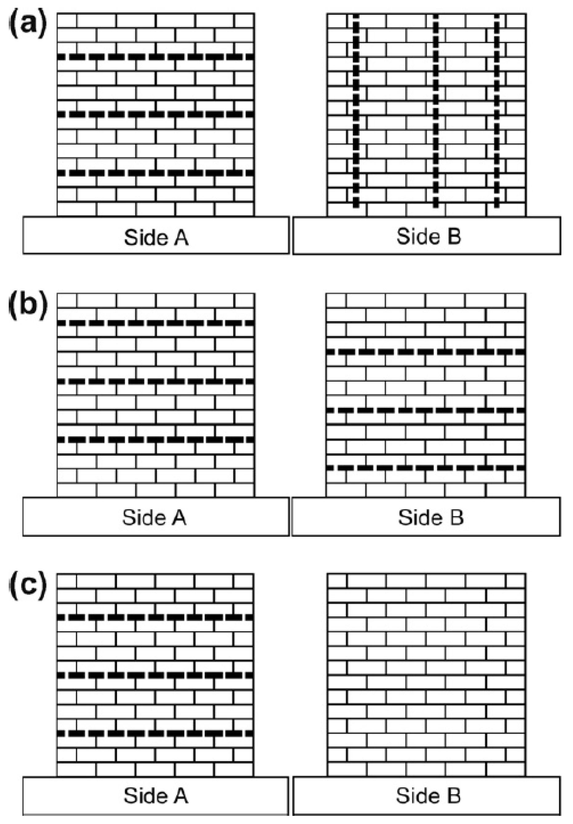
Figure 4.
CFRP retrofitting schemes [58]: (a) Scheme 1—three horizontal strips on one side and three vertical strips on the other side, (b) Scheme 2—six horizontal strips, three on each side, and (c) Scheme 3—three horizontal strips on one side only. Reproduced with permission from Konthesingha, K.M.C., Masia, M.J., Petersen, R.B., Mojsilovic, N., Simundic, G., and Page, A.W. Static cyclic in-plane shear response of damaged masonry walls retrofitted with NSM FRP strips—An experimental evaluation; published by Elsevier, Engineering Structures, 2013.

Figure 5.
Configurations of specimens [59]: (a) W1; (b) BW1-1; (c) W2; (d) BW1-1. Reproduced with permission from Zhang, S., Yang, D., Sheng, Y., Garrity, S.W. and Xu, L. Numerical modelling of FRP-reinforced masonry walls under in-plane seismic loading; published by Elsevier, Construction and Building Materials, 2017.

Figure 6.
CFRP reinforcement URM walls tests [30]: (a) Overall dimensions of the walls and configurations of the CFRP reinforcement, (b) Cracking pattern and failure modes of repaired and strengthened URM walls. Reproduced with permission from Santa-Maria, H., Alcaino, P. Repair of in-plane shear damaged masonry walls with external FRP; published by Elsevier, Construction and Building Materials, 2010.

Figure 7.
BFRP reinforcement URM walls tests [31]: (a) Test setup, (b) Instrumentation of the wall specimens. Reproduced with permission from Zhou, D.; Lei, Z.; Wang, J. In-plane behavior of seismically damaged masonry walls repaired with external BFRP; published by Elsevier, Composite Structures, 2013.

Figure 8.
Estimated shear strength of FRP-strengthened masonry samples according to the five models from Table 3 vs. experimental-to-theoretical FRP contribution ratios.
Figure 8.
Estimated shear strength of FRP-strengthened masonry samples according to the five models from Table 3 vs. experimental-to-theoretical FRP contribution ratios.

Publisher’s Note: MDPI stays neutral with regard to jurisdictional claims in published maps and institutional affiliations. |
© 2021 by the authors. Licensee MDPI, Basel, Switzerland. This article is an open access article distributed under the terms and conditions of the Creative Commons Attribution (CC BY) license (https://creativecommons.org/licenses/by/4.0/).
Share and Cite
MDPI and ACS Style
Hadzima-Nyarko, M.; Čolak, S.; Bulajić, B.Đ.; Ademović, N. Assessment of Selected Models for FRP-Retrofitted URM Walls under In-Plane Loads. Buildings 2021, 11, 559. https://0-doi-org.brum.beds.ac.uk/10.3390/buildings11110559
AMA Style
Hadzima-Nyarko M, Čolak S, Bulajić BĐ, Ademović N. Assessment of Selected Models for FRP-Retrofitted URM Walls under In-Plane Loads. Buildings. 2021; 11(11):559. https://0-doi-org.brum.beds.ac.uk/10.3390/buildings11110559
Chicago/Turabian StyleHadzima-Nyarko, Marijana, Stanko Čolak, Borko Đ. Bulajić, and Naida Ademović. 2021. "Assessment of Selected Models for FRP-Retrofitted URM Walls under In-Plane Loads" Buildings 11, no. 11: 559. https://0-doi-org.brum.beds.ac.uk/10.3390/buildings11110559
Note that from the first issue of 2016, this journal uses article numbers instead of page numbers. See further details here.