
Local Buckling Development of H-Section Steel Core of Buckling-Restrained Brace


1
School of Civil Engineering, Yantai University, Yantai 264005, China
2
Yantai Engineering and Technology College, Yantai 264006, China
3
School of Civil Engineering, Shandong Jianzhu University, Jinan 250101, China
4
Wanhua Building Technology Co., Ltd., Yantai 264006, China
*
Author to whom correspondence should be addressed.
Buildings 2022, 12(2), 227; https://0-doi-org.brum.beds.ac.uk/10.3390/buildings12020227
Submission received: 18 January 2022
/
Revised: 8 February 2022
/
Accepted: 14 February 2022
/
Published: 17 February 2022
(This article belongs to the Special Issue Resilience-Based Structural Seismic Design and Evaluation)
Abstract
:To enhance the theoretical basis for the half-wavelength evaluation of high-order local buckling of section steel used as inner core of buckling-restrained brace, this paper conducts theoretical and numerical studies on the local buckling development of an H-section steel core of buckling restrained brace. Firstly, the elastic buckling development of the flange under monotonic compression is theoretically discussed based on the elastic buckling theory of plate and the principle of virtual displacement. The numerical model for the buckling restrained brace with H-section steel core is then established based on Abaqus, and the elastic buckling development of the flange is validated. Finally, further numerical studies are conducted to reveal the elasto-plastic buckling development of the flange and web under cyclic loading. It is found that the local buckling development of the flange and web of the H-section steel core are different from that of the flat plate core of buckling restrained brace. Under cyclic loading, the shortest buckling wave of the flange and web are induced by the buckling of plates on the two sides of the contact point near the ends. It is confirmed that there is no need to consider the lateral support from the restraining members to evaluate the minimum half-wavelength of high-order local buckling for section steel core of buckling-restrained brace.
1. Introduction
Buckling-restrained braces (BRBs) have been widely used to improve the seismic performance of engineering structures for their excellent energy dissipation capability [1,2,3]. A well designed BRB can yield both in tension and compression and then provides stable elasto-plastic hysteretic behaviors. In local stability and fatigue design of BRBs, the half-wavelength of buckling of the inner core is a key parameter. For the flat plate core of BRB, the half-wavelength of buckling used to be commonly evaluated based on the classical Euler’s formula, where the flat core was regarded as a bar without any lateral restrains [4,5,6,7,8]. However, in BRBs, the inner core is actually continuously restrained by the restraining members, and due to the lateral support provided by the restraining members, the buckling wave of the flat plate core might be twice as long as that calculated based on the classical Euler’s formula [9,10,11]. As a result, it has been widely believed that the lateral support provided by the restraining members should be considered to evaluate the half-wavelength of buckling of the flat plate core, while directly adopting classical Euler’s formula for calculation is theoretically defective [9,10,11,12,13,14,15].
Recently, to provide greater stiffness and yield force in limited space, as well as for the advantages on global and local stability, section steels, especially H-section steels, have become increasingly popular in the fabrication of BRBs [16,17,18,19,20,21,22,23,24,25,26,27]. Test results showed that when the H-section steel core was effectively restricted, the high-order local buckling of the flange and web was the governmental buckling mode of the inner core [22,23,24,25], indicating that the half-wavelength of high-order local buckling of H-section steel core should be the key parameter for local stability design and fatigue analysis of corresponding BRBs. According to the research achievements based on the flat plate core mentioned above, it is natural to deduce that the lateral support provided by the restraining member should also be considered to evaluate the half-wavelength of high-order local buckling of H-section steel core. However, test results showed that the classical buckling theory of a plate with no lateral supports taken into account predicted the half-wavelength of high-order local buckling quite well, not only for the H-section steel core but also for the angle steel core [23,24,25,26,27].
Investigation into the buckling development of inner core is the basis for the half-wavelength evaluation. Large amounts of studies have been conducted on this aspect, however, most of them focused on the flat plate core, and the research on section steel cores were rather limited [28]. As a result, even if the evaluation method based on the classical buckling theory of plate with no lateral supports considered can well predict the half-wavelength of higher-order local buckling of section steel core, it still seems to be doubtful and theoretically defective.
Against this background, this paper conducts theoretical and numerical investigations on the local buckling development of an H-section steel core of BRB, to enhance the theoretical basis for the half-wavelength evaluation of high-order local buckling of section steel used as inner core of buckling-restrained brace. Firstly, theoretical analyses on the elastic buckling development of flange under monotonic compression based on the elastic buckling theory of plate and the principle of virtual displacement are described. Then, the numerical model for the BRB with H-section steel core is established and the elastic buckling development of the flange is validated. Finally, further numerical studies are conducted to reveal the elasto-plastic buckling development of the flange and web under cyclic loading, and the rationality of the existing half-wavelength evaluation method for higher-order local buckling of section steel cores of BRBs with no lateral supports considered is proved.
2. Theoretical Analyses on the Elastic Buckling Development of Flange
Given that the double integral of the shape function of web can hardly be obtained, only the elastic buckling development of flange is theoretically discussed in this section.
2.1. Analytical Model
To investigate the buckling behavior of the flange, buckling theory of plate should be used. As part of the core member of BRB, once the first order buckling occurs, the buckled flange will contact the restraining member and then an out-plane contact force P will be induced, as shown in Figure 1.
Meanwhile, when the clearance between inner core and restraining member is properly designed, the axial stress on the cross section of inner core can be regarded as uniformly distributed. Then, the analytical model for the restrained flange can be simplified as a rectangular plate with boundary conditions of “three edges simply supported, the other free” [23,24,25,27], under the combined action of in-plane uniform load Nx and out-plane contact force P (lateral support) in the middle of the free edge, as shown in Figure 1.
2.2. Elastic Buckling Development of Flange
Based on the analytical model presented in Figure 1 and the principle of virtual displacement, it can be obtained that [29],
where the left-hand side in this equation represents the work done during the virtual displacement by the lateral contact force P, the right-hand side is the corresponding change in the strain energy of the plate, Nx denotes the magnitude of axial in-plane force per unit length, D is the flexural rigidity of the plate, and w is the deflection of the plate. For the flange, the general expression for the deflection w that satisfies the boundary conditions of “three edges simply supported, the other free” is
where a and b are the length and width of the investigated flange, respectively, as shown in Figure 1, and am is an undetermined coefficient. Taking the derivative of Equation (2), it can be obtained that
It is worth noting that when
so
and then the items in the right-hand side of Equation (1) can be obtained as follows,
where mi is the specific value of coefficient m corresponding to δami.
As to the left-hand side in Equation (1), to obtain a virtual deflection δw, we give to a coefficient ami an increase δami. Then, based on Equation (2), the corresponding deflection of the plate is
The work done during this virtual displacement by the lateral force P is
where ξ and η are the coordinates of the location of lateral force P.
Substituting Equations (11)–(13) and (15) into Equation (1), it can be obtained that
Then substituting these values of the coefficients ami into Equation (2), the deflection of the plate can be found to be
Given that P acts in the middle of the free edge as shown in Figure 1, hence, the coordinates for the loading point of P are ξ = a/2 and η = b, then Equation (17) can be rewritten as follow.
Wu et al. used to conduct research on the buckling mode development of flat steel plate core of BRBs [9]. It was proved that under the increasing axial load Nx, the first order global buckling of the flat plate core would occur first as presented in Figure 2a, and with the increase in axial load, the curvature at the contact point would decrease to 0, followed by the appearance and development of a flat segment, as shown in Figure 2b. With the further increase in applied force, the flat segment would buckle, and then the higher order buckling of the flat core would appear, as shown in Figure 2c. In this paper, the buckling development of flange is theoretically discussed based on the same analysis procedure proposed by Wu et al., starting with the calculation of axial load when the curvature of the flange at the contact point is 0.
Substituting the coordinates of the contact point (x = a/2, y = b) into Equation (18) and then taking the second derivative of the deflection, it can be obtained that
Writing the axial uniform load Nx as
and setting Poisson Ratio , then Equation (19) becomes
For a given plate with a certain value of a/b, letting Equation (21) equal to 0, then the value of the coefficient k denoted as kx0 can be obtained. Substituting the obtained value of kx0 into Equation (20), the axial load Nx0 corresponding to that the curvature at the contact point is 0 can be obtained.
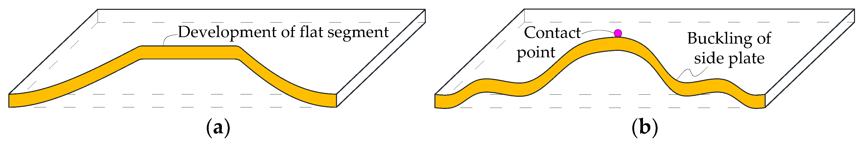
It should be noted that since the buckled flange touches the restraining member until the curvature at the contact point decreases to 0, the flange keeps point-contacted with the restraining member, indicating that there are no extra restraints on the flange plates locating on the two sides of the contact point during this process. As a result, the buckling load of the side flange plate as shown in Figure 1 can be investigated just based on the classical buckling theory of plate with no need to consider the lateral support. Denote the uniform axial load for the buckling of the side flange plate as Ncr, if Nx0 < Ncr, the development of the flat segment from the contact point will occur prior to the local buckling of the side flange plates, as shown in Figure 3a, then the buckling development of the flange will be similar to that of the flat steel core. In this case, the lateral support must be considered to estimate the half-wavelength of local buckling of the flange. However, if Nx0 > Ncr, the local buckling of the side flange plates will occur first, as shown in Figure 3b, and on this condition, the half-wavelength of high-order local buckling of the flange can be evaluated just based on the classical buckling theory of plate with no necessary to consider the lateral support, because except on the contact points, the side flange plate will not touch the restraining members until buckling.
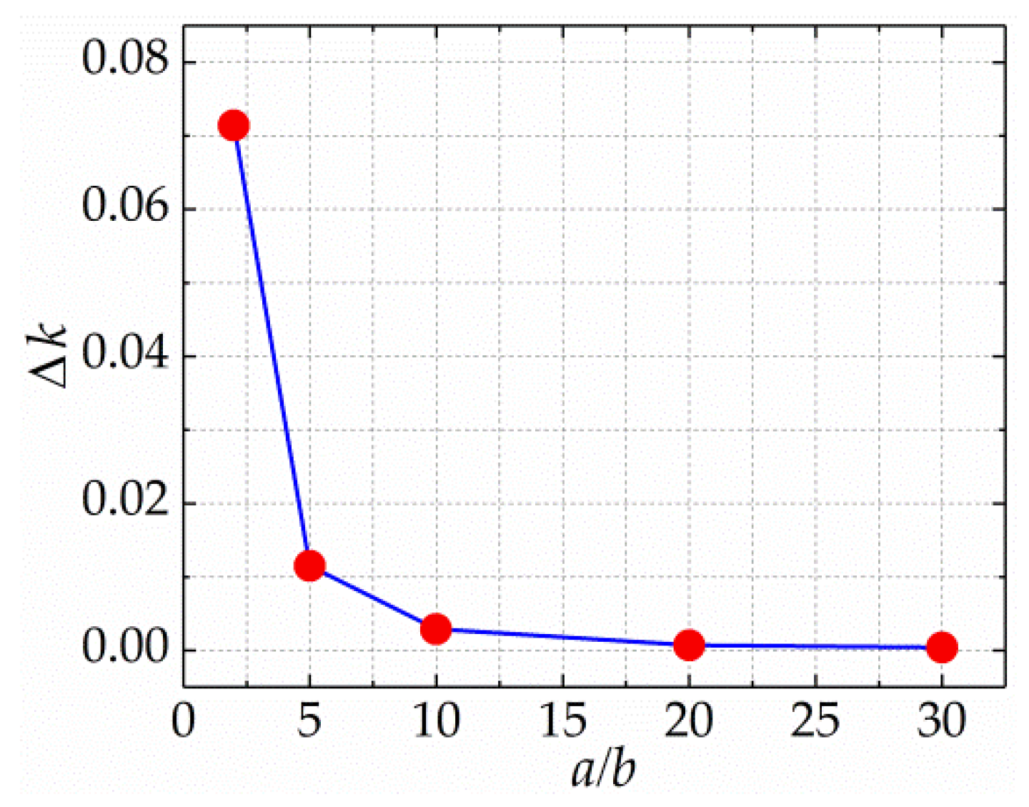
Setting Equation (21) to be 0, typically adopting different values of a/b and employing the first six values of m to calculate, the corresponding values of kx0 can be obtained. While, based on the classical buckling theory of plate [30,31], the values of coefficient kcr for the local buckling of side flange plate can be achieved with Equation (22), where b and as = 0.5a are the width and length of the side flange plate, as shown in Figure 1.
The values of kx0 and kcr under different values of a/b are listed in Table 1, and the relationship between Δk = kx0 − kcr and a/b is presented in Figure 4. It can be observed that kx0 is always larger than kcr, and the difference between them aggravates with the decrease in a/b, indicating that Nx0 > Ncr is always true especially for short plates. As discussed above, Nx0 > Ncr means that the local buckling of the side flange plate occurs prior to the development of the flat segment, hence it can be proved that the buckling development of the flange is different from that of the flat plate core, and there is no need to consider the lateral support to evaluate the half-wavelength of high-order local buckling of the flange, at least in the elastic range.
3. Establishment of Numerical Model
To validate the elastic buckling development of the restrained flange discussed above, as well as to further investigate the elasto-plastic buckling development of H-section steel core under cyclic loading, the numerical model for a typical BRB with an H-section steel core is established in this section.
The authors used to develop and conduct experimental studies on a type of BRB with an H-section steel core restrained by two U-shaped steels and two restraining plates, as shown in Figure 5 [22,23]. According to the specimen labeled S3 in reference [23], the numerical model used for analysis in this paper is established based on the finite element program Abaqus, where the length of the H-section steel core and restraining members are all 1050 mm, and the total thickness of the clearance between H-section steel core and restraining members is assigned to be 2 mm. Detailed cross-sectional dimensions of the H-section steel core, U-shaped steel and restraining plate for the numerical model can be found in Figure 6.
It should be pointed out that, actually, the two U-shaped steels and two restraining plates were assembled by fillers and high-strength bolts to form the restraining member as shown in Figure 5. In this paper, to simplify the numerical model and, thus, to improve the efficiency of numerical simulation, the bolt connections are not simulated. Instead, the fillers, the U-shaped steels and the restraining plates are directly merged together to become a whole, as shown in Figure 7.
To investigate the buckling development of H-section steel core, an initial imperfection has to be applied, or the ideal H-section steel core will be always under axial compression and the buckling will never occur. In this paper, a small value of the first order global buckling around the weak axis of the H-section steel core is assumed as the initial imperfection, with the peak magnitude being 5/10,000 of the core length. The H-section steel core and restraining components are all modeled by eight-node solid elements with incompatible mode(C3D8I). The interaction between the H-section steel core and restraining members is represented by a hard contact behavior, allowing separation of the interface in tension and no penetration in compression. Given that, for a properly designed BRB, the effects of friction on the buckling mode and half-wavelength of buckling of inner core are limited [11,15], the tangential behavior of the interaction is not considered in this paper. The end elements of the flanges and web could rotate but are constrained to move only in the longitudinal direction without any other deformation or torsion. For the numerical solution, the full Newton method is adopted by default.
4. Elastic Buckling Development of H-Section Steel Core
To validate the elastic buckling development of the flange as discussed in Section 2.2, the pure elastic property with the elastic modulus of 2.0 × 10⁵ MPa and the Poisson ratio of 0.3 is assigned to the H-section steel core and restraining members in this section. Then, an axially compressive displacement is monotonically applied to the H-section steel core until the compressive strain reaches 2%. It should be noted that because the H-section steel core is set to be elastic, although the maximum strain reaches 2% in compression, the H-section steel core still deforms elastically, and thus can be used to validate the theoretical deduction on the elastic buckling development of the flange mentioned in Section 2.2 of this paper.
With the increase in axial displacement, the elastic buckling mode of the H-section steel core at different strain values are presented in Figure 8, where ε is the core strain obtained with the relative deformation between the two ends divided by the core length of 1050 mm, and the buckling deformation of the H-section steel core is magnified by 25 times for better presentation. It has been proved that, for the flat plate core of BRB, after the buckled plate touches the restraining member, the contact form will develop from one-point contact to two-points contact with a flat segment between the contact points, and the flat segment will buckle prior to the buckling of the side plates under the increasing axial load [9,10,11]. However, for the H-section steel core, as can be observed from Figure 8, after the buckled flange touches the restraining member, no flat segment appears, instead, the local buckling of flange plates locating on both sides of the contact point occurs and develops significantly, which is rather different from the buckling development of the flat plate core, but agrees quite well with the deduction proposed in Section 2.2 of this paper.
Based on the changes of stress nephogram, the buckling development of the web can also be investigated. The buckling of the web in compression leads to non-uniform stress distribution, with the stress of bending compressive elements being larger than that of the bending tensile elements. In the mises stress nephogram of Abaqus, the magnitude of stress is represented by the intensity of color. As a result, based on the distribution and changes of web elements’ color, the buckling development of the web can be discussed qualitatively. As shown in Figure 8, no flat segment can be observed on the web, and it is quite obvious that the inhomogeneous web element colors develop from both sides to the contact point in the middle. This indicates that the local buckling of the side web plate occurs prior to the development of flat segment, which is different from the buckling development of flat plate core but quite similar to that of the flange.
5. Elasto-Plastic Buckling Development of H-Section Steel Core
5.1. Numerical Model and Loading Protocol
Buckling-restrained braces are usually used as damping devices in seismic prone areas with the input energy dissipated by the elasto-plastic deformation of the core member. As a result, it is quite necessary to investigate the elasto-plastic buckling behavior of the inner core for better design of BRBs. Given that the elasto-plastic plate is bidirectional orthotropic [30,31], theoretical derivation like that in the elastic stage can hardly be conducted, hence, the elasto-plastic buckling behavior of the flange and web for H-section steel core are investigated through numerical simulations in this section.
The numerical model established in Section 3 of this paper is also used here, but a double-line elasto-plastic property is applied to the components, where the yield strength is set to be 300 MPa according to the material test results [23] and the post-yield modulus is 2% of the elastic modulus. Then the H-section steel core is cyclically loaded with the target core strain of ±3.5% (target relative displacement between the two ends of H-section steel core of ±36.75 mm divided by the core length of 1050 mm) starting with compression, as shown in Figure 9.
5.2. Simulation Results
The buckling mode of H-section steel core at different strain values in compression under cyclic loading are listed in Figure 10, Figure 11 and Figure 12, where the buckling deformation is magnified by 15 times to present. It can be found that, once the elasto-plastic property is considered, the buckling development of the H-section steel core is different from that with elastic property.
As shown in Figure 10, when the H-section steel core is compressed for the first time, with the increase in axial strain, a flat segment of the flange appears and then a slight buckling of the flat segment can be observed. However, an important phenomenon worth noting is that although the flat segment appears and buckles slightly, the local buckling of the side flange plate occurs earlier and develops more promptly, as exhibited in Figure 10b–f. For the web, it can be observed that the nonuniformity of the elements’ color appears first at both ends and then extends to the middle, indicating that the high-order local buckling of the web also develops from both sides to the center.
As the cyclic loading goes on, when the H-section steel core is compressively loaded in the second loading cycle, due to the existence of residual deformation caused by the elasto-plastic buckling from the previous step, the H-section steel core works with a high-order initial imperfection. In addition, under cyclic loading, the yield strength of H-section steel core also decreases due to the Bauschinger effect. As a result, the high-order buckling of the flange and web appear much earlier and develop more severely than those in the first loading cycle, and the buckling of the flat segment of the flange, which was quite slight in the previous step, becomes more obvious here, as shown in Figure 11. It should be pointed out that although the serious buckling of the flat segment finally occurs, the high-order local buckling of the flange and web still originate from the two ends, as shown in Figure 11a,b. In addition, as denoted in Figure 11f, it can be found that not only for the flange but also for the web, the shortest buckling wave is induced by the buckling of the side plate rather than that of the flat segment in the middle, hence, the buckling of the side plate should be the focus for half-wavelength evaluation of high-order local buckling of section steel cores in BRBs.
Based on Figure 10 and Figure 11, it can be observed that the buckling developments of H-section steel core under compression for the first and second time are different, due to the influences of residual deformation and Bauschinger effect. However, when the compressive load is applied for the third time, no obvious changes of the buckling development of H-section steel core can be observed compared with that in the second loading cycle. As presented in Figure 12, no higher-order local buckling of the flange or web occurs, and the shortest buckling wave still appears on the side plates, indicating that the influences of residual deformation and Bauschinger effect tend to be stabilized, and as a result, no more cyclic loadings are needed.
Based on the simulation results presented in Figure 10, Figure 11 and Figure 12, it can be found that once considering the elasto-plastic property of H-section steel core, a flat segment developing from the contact point will appear and then buckle under cyclic loading, which is different from the elastic buckling development exhibited in Section 4 of this paper. However, it should be pointed out that although the flat segment appears and buckles, the buckling of the side flange and web plate always occur earlier and develop more promptly, and more importantly, the shortest buckling wave is found to be induced by the buckling of the side plate near the ends rather than the buckling of the flat segment. In local stability design and fatigue life analysis of BRBs, the minimum half-wavelength of local buckling directly related to the largest contact force and bending strain is the key parameter. For the H-section steel core, given that the shortest buckling wave results from the buckling of the side plate, and when the buckling occurs, there are no additional restraining effects on the side plate except for the contact force on the contact point, there is no need to consider the lateral support to evaluate the minimum half-wavelength of local buckling for H-section steel core, and this conclusion also suits for other section steel cores of BRBs.
5.3. Validation of Half-Wavelength of Local Buckling for Flange
The authors used to propose a method for the minimum half-wavelength evaluation of high-order local buckling for the flange of H-section steel core and angle steel core of BRBs [23], as presented by Equations (23) and (24), where a is the half-wavelength to be calculated, b and t are the width and thickness of the flange, σ denotes the in-plane stress applied on the flange plate, v is the Poisson’s ratio, η* is the modulus degradation factor, E and Et represent the elastic and tangent modulus of the material of flange.
For the flange of H-section steel core investigated in this paper, it can be found from Figure 6 and Section 5.1 that b = 47 mm, t = 7 mm, v = 0.3, E = 2.0 × 10⁵ MPa, Et/E = 0.02, and the compressive stress of σ = 450 MPa at ultimate strain can be obtained by dividing the cross-sectional area of H-section steel core into the reaction force extracted from the numerical model. Based on these values, the minimum half-wavelength of the flange is estimated to be 61.4 mm. As presented in Figure 12f, the measured minimum numerical half-wavelength is about 67.5 mm, which agrees well with the theoretical value, indicating that the numerical model can be used for the investigation of the buckling development of H-section steel core, and the aforementioned conclusion that there is no need to consider the lateral support to evaluate the minimum half-wavelength of local buckling for section steel cores is further proved.
6. Conclusions
To enhance the theoretical basis for the minimum half-wavelength evaluation of high-order local buckling of section steel cores in BRBs, theoretical and numerical studies are conducted on the buckling development of an H-section steel core in this paper. The main achievements and conclusions of this study are as follows:
(1) Theoretical and numerical analysis prove that the elastic buckling development of the flange of H-section steel core is different from that of the flat plate core, the local buckling of the side flange plate rather than the development of the flat segment is dominant with the increase of axial displacement.
(2) Under cyclic loading with elasto-plastic property considered, the shortest buckling wave of the flange as well as the web is induced by the buckling of the side plate near the end rather than the buckling of the flat segment in the middle.
(3) It is confirmed that there is no need to consider the lateral support to evaluate the minimum half-wavelength of high-order local buckling for section steel cores of BRBs.
Author Contributions
Conceptualization, W.L.; methodology, W.L.; software, W.L. and L.W.; validation, J.D. and H.Q.; formal analysis, W.L.; investigation, W.L. and L.W.; resources, H.Q., L.W. and K.Z.; data curation, J.D.; writing—original draft preparation, W.L.; writing—review and editing, H.Q.; visualization, J.D.; supervision, H.Q. and L.W.; project administration, W.L. and L.W.; funding acquisition, L.W. and H.Q. All authors have read and agreed to the published version of the manuscript.
Funding
This research was funded by Natural Science Foundation of Shandong Province of China, grant number ZR2019PEE033; Shandong Provincial Key Lab of Appraisal and Retrofitting in Building Structures (Shandong Jianzhu University).
Institutional Review Board Statement
Not applicable.
Informed Consent Statement
Not applicable.
Data Availability Statement
The data presented in this study are available on request from the corresponding author.
Acknowledgments
Gratefully acknowledgment is given to Bin Wu at Wuhan University of Technology for the guidance and suggestions on theoretical analyses.
Conflicts of Interest
The authors declare no conflict of interest.
References
- Uang, C.M.; Nakashima, M.; Tsai, K.C. Research and Application of Buckling-restrained Braced Frames. Int. J. Steel Struct. 2004, 4, 301–313. [Google Scholar]
- Xie, Q. State of the art of buckling-restrained braces in Asia. J. Constr. Steel Res. 2005, 61, 727–748. [Google Scholar] [CrossRef]
- Takeuchi, T.; Wada, A. Review of Buckling-Restrained Brace Design and Application to Tall Buildings. Int. J. High-Rise Build. 2018, 7, 187–195. [Google Scholar]
- Chou, C.-C.; Chen, S.-Y. Subassemblage tests and finite element analyses of sandwiched buckling-restrained braces. Eng. Struct. 2010, 32, 2108–2121. [Google Scholar] [CrossRef]
- Takeuchi, T.; Hajjar, J.; Matsui, R.; Nishimoto, K.; Aiken, I. Local buckling restraint condition for core plates in buckling restrained braces. J. Constr. Steel Res. 2010, 66, 139–149. [Google Scholar] [CrossRef]
- Takeuchi, T.; Hajjar, J.F.; Matsui, R.; Nishimoto, K.; Aiken, I.D. Effect of local buckling core plate restraint in buckling restrained braces. Eng. Struct. 2012, 44, 304–311. [Google Scholar] [CrossRef]
- Wu, A.-C.; Lin, P.-C.; Tsai, K.-C. High-mode buckling responses of buckling-restrained brace core plates. Earthq. Eng. Struct. Dyn. 2013, 43, 375–393. [Google Scholar] [CrossRef]
- Lin, P.-C.; Tsai, K.-C.; Wang, K.-J.; Yu, Y.-J.; Wei, C.-Y.; Wu, A.-C.; Tsai, C.-Y.; Lin, C.-H.; Chen, J.-C.; Schellenberg, A.H.; et al. Seismic design and hybrid tests of a full-scale three-story buckling-restrained braced frame using welded end connections and thin profile. Earthq. Eng. Struct. Dyn. 2011, 41, 1001–1020. [Google Scholar] [CrossRef]
- Wu, B.; Mei, Y. Buckling mechanism of steel core of buckling-restrained braces. J. Constr. Steel Res. 2015, 107, 61–69. [Google Scholar] [CrossRef]
- Wu, B.; Lu, J.; Mei, Y.; Zhang, J. Buckling mechanism and global stability design method of buckling-restrained braces. J. Constr. Steel Res. 2017, 138, 473–487. [Google Scholar] [CrossRef]
- Lu, J.; Wu, B.; Mei, Y. Buckling mechanism of steel core and global stability design method for fixed-end buckling-restrained braces. Eng. Struct. 2018, 174, 447–461. [Google Scholar] [CrossRef]
- Wu, J.; Liang, R.J.; Wang, C.L.; Ge, H.B. Restrained Buckling Behavior of Core Component in Buckling-restrained Braces. Int. J. Adv. Steel Constr. 2012, 8, 212–225. [Google Scholar]
- Genna, F.; Gelfi, P. Analysis of the Lateral Thrust in Bolted Steel Buckling-Restrained Braces. II: Engineering Analytical Estimates. J. Struct. Eng. 2012, 138, 1244–1254. [Google Scholar] [CrossRef]
- Chen, Q.; Wang, C.L.; Meng, S.; Zeng, B. Effect of the Unbonding Materials on the Mechanic Behavior of All-steel Buckling-restrained Braces. Eng. Struct. 2016, 111, 478–493. [Google Scholar] [CrossRef]
- Jiang, Z.Q.; Guo, Y.L.; Zhang, B.H.; Zhang, X.Q. Influence of Design Parameters of Buckling-restrained Brace on its Performance. J. Constr. Steel Res. 2015, 105, 139–150. [Google Scholar] [CrossRef]
- Oda, H.; Usami, T. Fabricating Buckling-restrained Braces from Existing H-section Bracing Members: Experimental Study. J. Struct.Eng. JSCE 2010, 56, 499–510. (In Japanese) [Google Scholar]
- Funayama, J.; Imase, F.; Usami, T.; Wang, C.L. Seismic Upgrade Effect of Steel Truss Structures with H-section BRBs. Proc. JSCE Earthq. Eng. Symp. 2012, 68, 730–747. (In Japanese) [Google Scholar]
- Usami, T.; Kaneko, H. Strength of H-shaped Brace Constrained Flexural Buckling Having Unconstrained Area at Both Ends (Both Ends Simply Supported). J. Struct. Constr. Eng. Archit. Inst. Jpn. 2001, 542, 171–177. (In Japanese) [Google Scholar] [CrossRef] [Green Version]
- Usami, T.; Kaneko, H.; Ono, T. Strength of H-shaped Brace Constrained Flexural Buckling Having Unconstrained Area at Both Ends (Both Ends Fixed). J. Struct. Constr. Eng. Archit. Inst. Jpn. 2002, 558, 211–218. (In Japanese) [Google Scholar] [CrossRef] [Green Version]
- Ju, Y.K.; Kim, M.H.; Kim, J.; Kim, S.D. Component Tests of Buckling-restrained Braces with Unconstrained Length. Eng. Struct. 2009, 31, 507–516. [Google Scholar] [CrossRef]
- Kim, D.H.; Lee, C.H.; Ju, Y.K.; Kim, S.D. Subassemblage Test of Buckling-restrained Braces with H-shaped Steel Core. Struct. Des. Tall Spec. Build. 2015, 24, 243–256. [Google Scholar] [CrossRef]
- Li, W.; Wu, B.; Ding, Y. Experimental Study on Seismic Behaviors of H-section Steel Buckling-restrained Braes. J. Build. Struct. 2013, 34, 94–102. [Google Scholar]
- Li, W.; Wu, B.; Ding, Y.; Zhao, J.X. Experimental Performance of Buckling-restrained Braces with Steel Cores of H-section and Half-wavelength Evaluation of Higher-order Local Buckling. Adv. Struct. Eng. 2017, 20, 641–657. [Google Scholar] [CrossRef]
- Wang, C.L.; Gao, Y.; Cheng, X.Q.; Zeng, B.; Zhao, S.L. Experimental Investigation on H-section Buckling-restrained Braces with Partially Restrained Flange. Eng. Struct. 2019, 199, 109584. [Google Scholar] [CrossRef]
- Yuan, Y.; Gao, J.W.; Qing, Y.; Wang, C.L. A New H-section Buckling-restrained Brace Improved by Movable Steel Blocks and Stiffening Ribs. J. Build. Eng. 2022, 45, 103650. [Google Scholar] [CrossRef]
- Zhao, J.X.; Wu, B.; Ou, J.P. A Novel Type of Angle Steel Buckling-restrained Brace: Cyclic Behavior and Failure Mechanism. Earthq. Eng. Struct. Dyn. 2011, 40, 1083–1102. [Google Scholar] [CrossRef]
- Zhao, J.X.; Wu, B.; Li, W.; Ou, J.P. Local Buckling Behavior of Steel Angle Core Members in Buckling-restrained braces: Cyclic Tests, Theoretical Analysis, and Design Recommendations. Eng. Struct. 2015, 66, 129–145. [Google Scholar] [CrossRef]
- Piluso, V.; Pisapia, A. Interactive Plastic Local Buckling of Box-shaped Aluminium Members under Uniform Compression. Thin-Walled Struct. 2021, 164, 107828. [Google Scholar] [CrossRef]
- Timoshenko, S.P.; Woinowsky-Krieger, S. Theory of Plates and Shells, 2nd ed.; McGraw-Hill Book Company: New York, NY, USA, 1987; p. 387. [Google Scholar]
- Chen, J. Stability of Steel Structures: Theory and Design, 4th ed.; Science Press: Beijing, China, 2008; p. 414. (In Chinese) [Google Scholar]
- Bleich, F. Buckling Strength of Metal Structures; McGraw-Hill Publishing Company: New York, NY, USA, 1952; p. 307. [Google Scholar]
Figure 1.
Theoretical analysis model for the flange of H-section steel core.

Figure 2.
Buckling development of flat plate core of BRB. (a) One point contact. (b) Development of flat segment. (c) Higher buckling mode.
Figure 2.
Buckling development of flat plate core of BRB. (a) One point contact. (b) Development of flat segment. (c) Higher buckling mode.

Figure 3.
Buckling mode of flange plate under different conditions. (a) Nx0 < Ncr. (b) Nx0 > Ncr.

Figure 4.
Relationship between Δk and a/b.

Figure 5.
Configuration of the prototype specimen for the numerical model adapted from Ref. [23]. (a) Assembly of the prototype specimen. (b) Layout of the high strength bolts.
Figure 5.
Configuration of the prototype specimen for the numerical model adapted from Ref. [23]. (a) Assembly of the prototype specimen. (b) Layout of the high strength bolts.

Figure 6.
Detailed geometric dimensions of the numerical model (Unit: mm).

Figure 7.
Numerical model for the H-section steel core and restraining member.

Figure 8.
Elastic buckling development of the H-section steel core under monotonic compression. (a) ε = 0%. (b) ε = 1.02%. (c) ε = 1.46%. (d) ε = 1.50%. (e) ε = 1.51%. (f) ε = 1.52%. (g) ε = 1.83%. (h) ε = 2.00%.
Figure 8.
Elastic buckling development of the H-section steel core under monotonic compression. (a) ε = 0%. (b) ε = 1.02%. (c) ε = 1.46%. (d) ε = 1.50%. (e) ε = 1.51%. (f) ε = 1.52%. (g) ε = 1.83%. (h) ε = 2.00%.

Figure 9.
Cyclic loading protocol.

Figure 10.
Buckling development of H-section steel core in compression of the first loading cycle. (a) ε = 0. (b) ε = 1.28%. (c) ε = −2.18%. (d) ε = −3.08%. (e) ε = −3.30%. (f) ε = −3.50%.
Figure 10.
Buckling development of H-section steel core in compression of the first loading cycle. (a) ε = 0. (b) ε = 1.28%. (c) ε = −2.18%. (d) ε = −3.08%. (e) ε = −3.30%. (f) ε = −3.50%.

Figure 11.
Buckling development of H-section steel core in compression for the second time. (a) ε = 0. (b) ε = −0.67%. (c) ε = −1.28%. (d) ε = −2.08%. (e) ε = −2.97%. (f) ε = −3.50%.
Figure 11.
Buckling development of H-section steel core in compression for the second time. (a) ε = 0. (b) ε = −0.67%. (c) ε = −1.28%. (d) ε = −2.08%. (e) ε = −2.97%. (f) ε = −3.50%.

Figure 12.
Buckling development of H-section steel core in compression for the third time. (a) ε = 0. (b) ε = −0.67%. (c) ε = −1.22%. (d) ε = −2.07%. (e) ε = −2.87%. (f) ε = −3.50%.
Figure 12.
Buckling development of H-section steel core in compression for the third time. (a) ε = 0. (b) ε = −0.67%. (c) ε = −1.22%. (d) ε = −2.07%. (e) ε = −2.87%. (f) ε = −3.50%.


Table 1.
Values of the buckling coefficients with the change of a/b.
| a = 30b | a = 20b | a = 10b | a = 5b | a = 2b | |
|---|---|---|---|---|---|
| kx0 | 0.4298 | 0.4357 | 0.4679 | 0.5965 | 1.4964 |
| kcr | 0.4294 | 0.4350 | 0.4650 | 0.5850 | 1.4250 |
| Δk | 0.0004 | 0.0007 | 0.0029 | 0.0115 | 0.0714 |
Publisher’s Note: MDPI stays neutral with regard to jurisdictional claims in published maps and institutional affiliations. |
© 2022 by the authors. Licensee MDPI, Basel, Switzerland. This article is an open access article distributed under the terms and conditions of the Creative Commons Attribution (CC BY) license (https://creativecommons.org/licenses/by/4.0/).
Share and Cite
MDPI and ACS Style
Li, W.; Dong, J.; Qu, H.; Wang, L.; Zhao, K. Local Buckling Development of H-Section Steel Core of Buckling-Restrained Brace. Buildings 2022, 12, 227. https://0-doi-org.brum.beds.ac.uk/10.3390/buildings12020227
AMA Style
Li W, Dong J, Qu H, Wang L, Zhao K. Local Buckling Development of H-Section Steel Core of Buckling-Restrained Brace. Buildings. 2022; 12(2):227. https://0-doi-org.brum.beds.ac.uk/10.3390/buildings12020227
Chicago/Turabian StyleLi, Wei, Jing Dong, Hui Qu, Lanqin Wang, and Kun Zhao. 2022. "Local Buckling Development of H-Section Steel Core of Buckling-Restrained Brace" Buildings 12, no. 2: 227. https://0-doi-org.brum.beds.ac.uk/10.3390/buildings12020227
Note that from the first issue of 2016, this journal uses article numbers instead of page numbers. See further details here.