
Carbonation and Corrosion Problems in Reinforced Concrete Structures


1
Materials Engineering Department, College of Engineering, King Faisal University, Al-Hofuf 31982, Saudi Arabia
2
Civil and Environmental Engineering Department, College of Engineering, King Faisal University, Al-Hofuf 31982, Saudi Arabia
*
Author to whom correspondence should be addressed.
Buildings 2022, 12(5), 586; https://0-doi-org.brum.beds.ac.uk/10.3390/buildings12050586
Submission received: 15 March 2022
/
Revised: 22 April 2022
/
Accepted: 27 April 2022
/
Published: 2 May 2022
(This article belongs to the Section Building Structures)
Abstract
:Reinforced concrete (RC) has been commonly used as a construction material for decades due to its high compressive strength and moderate tensile strength. However, these two properties of RC are frequently hampered by degradation. The main degradation processes in RC structures are carbonation and the corrosion of rebars. The scientific community is divided regarding the process by which carbonation causes structural damage. Some researchers suggest that carbonation weakens a structure and makes it prone to rebar corrosion, while others suggest that carbonation does not damage structures enough to cause rebar corrosion. This paper is a review of the research work carried out by different researchers on the carbonation and corrosion of RC structures. The process of carbonation and the factors that contribute to this process will be discussed, alongside recommendations for improving structures to decrease the carbonation process. The corrosion of rebars, damage to passive layers, volume expansion due to steel oxidation, and crack growth will also be discussed. Available protection methods for reducing carbonation, such as rebar structure coating, cathodic protection, and modifier implementation, will also be reviewed. The paper concludes by describing the most significant types of damage caused by carbonation, testing protocols, and mitigation against corrosion damage.
1. Introduction to Carbonation and Its Mechanisms
Concrete is made by creating a paste out of Portland cement and water. This paste is essential for coating and bonding small and large aggregates to form masses of concrete. Concrete becomes harder and stronger as the paste undergoes a chemical reaction called hydration. Despite having very high compressive strength, concrete has low tensile strength. Therefore, steel bars can be embedded in concrete to improve its tensile strength; such concrete is called reinforced concrete (RC). RC is a frequently-used construction material in buildings, bridges, power plants, pipelines, and other infrastructure elements. Therefore, infrastructure often deteriorates with age because of carbonation-induced steel corrosion. Carbonation occurs when two of the compounds present in concrete, namely carbon dioxide (CO2) and calcium hydroxide (Ca(OH)2), react to produce calcium carbonate (CaCO3) [1,2]. The estimated annual maintenance cost associated with corrosion in homes, commercial buildings, bridges, dams, ports, and other physical infrastructure elements worldwide exceeds $1.8 trillion, which translates to 3–4% of the gross domestic product (GDP) of industrialized countries [1,2,3]. Therefore, preventing corrosion or rust is vital to ensure the durability of RC and the maintenance of related economic activities.
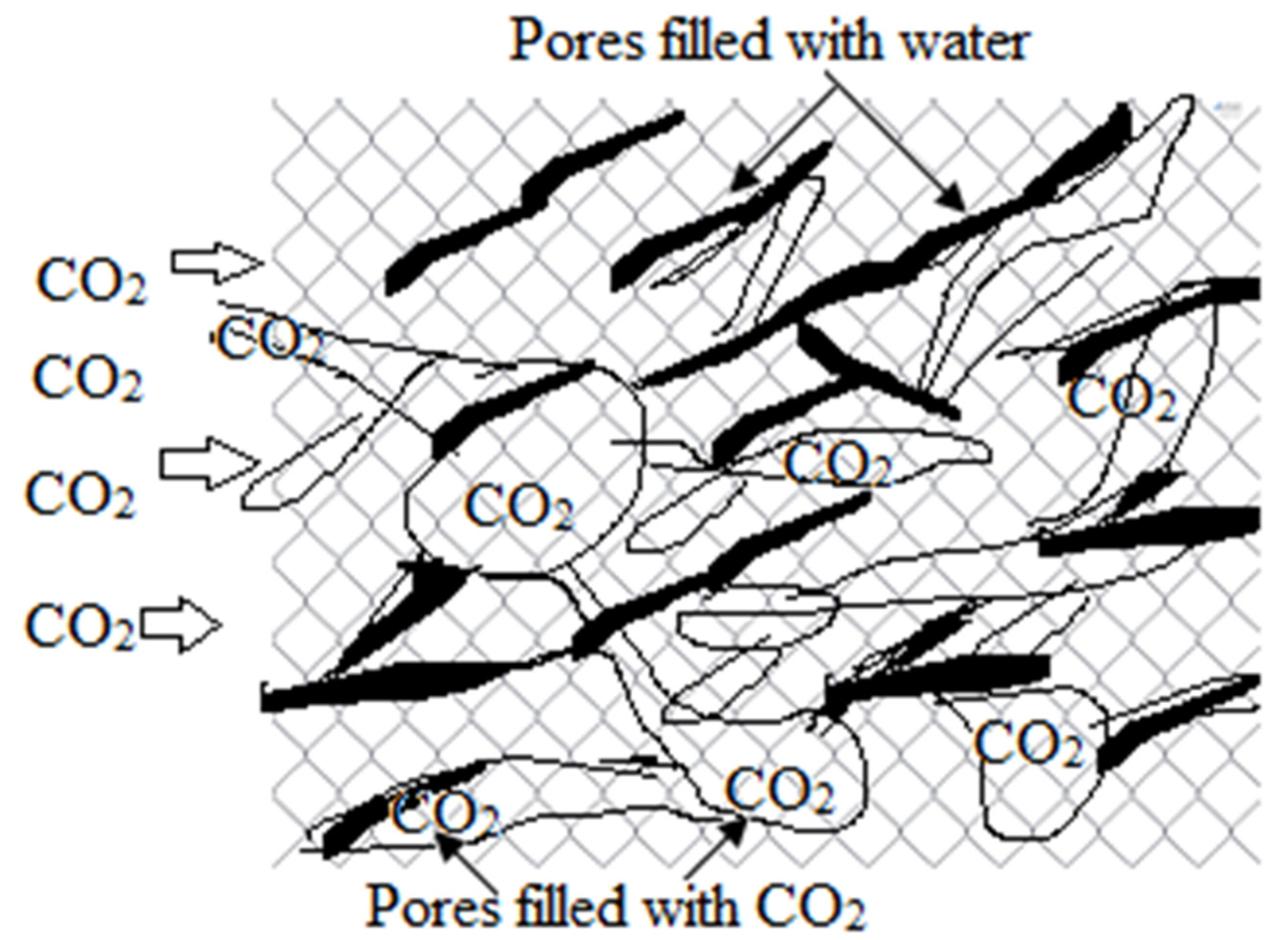
Carbonation occurs when CO2, as natural gas in the air, penetrates the surface of concrete through the dry portions of interconnected pores in concrete microstructures, and reacts with Ca(OH)2 in the moist portions of pores to form CaCO3 and water (H2O) [3,4].
CO2 + Ca(OH)2 + → CaCO3 + H2O
When Ca(OH)2 from the paste is consumed, the hydration of calcium-silicate-hydrate (C-S-H) releases calcium oxide (CaO), which reacts with diffused CO2 to form carbonates. The remaining CO2 continues to react with C-S-H to form additional CaCO3. The carbonation process requires water because CO2 dissolves in water to form carbonic acid H2CO3 [2]. The schematic diagram in Figure 1 depicts the adsorption of water and CO2 by concrete. The water seeps in through small, interconnected pores, while CO2 settles in large pores. The interconnected pores merge into large pores to supply the water required to form carbonic acid:
CO2 + H2O → H2CO3
A chemical reaction occurs with H2CO3, which is formed in the pores of the concrete, producing a desirable product of cement hydration Ca(OH)2, which strengthens the concrete matrix. This reaction also produces CaCO3 and water [1,3,6,7]:
H2CO3 + Ca (OH) 2 + → CaCO3 + 2H2O
Carbonation destroys a passive layer formed by alkaline concrete, but does not influence the rate of corrosion. An oxide film of corrosion products covers metal surfaces and acts as a barrier preventing additional chemical reactions. This is the main function of the passive layer in decreasing corrosion damage [8].
A high-alkaline concrete environment creates a passive film around steel bars. Concrete is considered high-alkaline when its pH is around 12.5 because 25% to 50% of the weight of the fresh cement paste is Ca(OH)2. The chemical reaction that forms the passive film is as follows: the hydroxide (OH-) from the solution first reacts with dissolved iron (Fe) in the outer passive film layer. This reaction produces iron hydroxide (Fe(OH)2), which further reacts with oxygen and water to form ferric iron(III) oxide hydroxide (Fe(OH)3), which is the passive layer, as shown in the following chemical reaction equations [8]:
Fe2+ + 2OH− → Fe(OH)2
Fe(OH)2 + 0.5 O2 + H2O → Fe(OH)3
The carbonation reaction reduces the pH of the pore solution to less than 9 because of Ca(OH)2 reduction, which leads to the destruction of the passive oxide layer protecting the steel bars from corrosion [9]. However, carbonation increases the compressive and tensile strength of concrete. When the passive layer breaks down due to carbonation, the bond between the steel bars and the concrete is broken. Consequently, corrosion occurs in the steel bars, causing their strength to decrease and their volume to increase [2]. Subsequently, the increased volume of corroded steel bars leads to internal stress within the concrete, which may cause cracking or spalling in the concrete cover and reduced structural capacity of structural elements such as columns and beams.
1.1. Factors Contribute to Carbonation
The main factors that cause carbonation are dry-wet cycles, relative humidity, temperature, and CO2 concentration, all of which are environmental factors. Moreover, certain factors that lead to carbonation are related to concrete’s microstructural properties and materials, such as concrete’s porous structure and the number of chemical compounds that can react to form carbonation [7].
Low-permeability concrete can restrict CO2 penetration if it has a low water-to-cement ratio, high cement content, and high compressive strength [2]. This is because an increase in the water-to-cement ratio can be related to increased porosity and CO2 transport. Furthermore, if the concrete is completely dry or wet, carbonation does not occur unless the relative humidity is between 50% and 70%. If the relative humidity is below 50%, the moisture level is not adequate for reactions to take place; if the relative humidity is above 70%, the high level of moisture in pores restricts CO2 penetration [10]. The optimum relative humidity for the carbonation process is 65% [11].
Moreover, a previous study revealed that CO2 penetration increases as temperature increases, as higher temperatures make concrete more porous [12,13]. In 2005, the atmospheric CO2 concentration was about 380 parts per million (PPM), up from 280 PPM in 1975; this increase occurred because of temperature changes. Therefore, climate change has accelerated the initiation of corrosion in RC by enabling harmful substances from the environment, such as CO2 and chloride, to penetrate RC. For example, if the temperature increases by 2 °C because of global warming, the steel corrosion rate may increase by 15% [1,10]. In addition, the mean daily temperature affects the carbonation depth. For example, if a concrete structure is located in an area with a mean daily temperature of 27 °C, it will undergo more carbonation than the same structure located in an area with a mean daily temperature of 9 °C [11]. Furthermore, carbonation often occurs in areas of building facades that are exposed to rainfall, shaded from sunlight, or located in indoors [12,14].
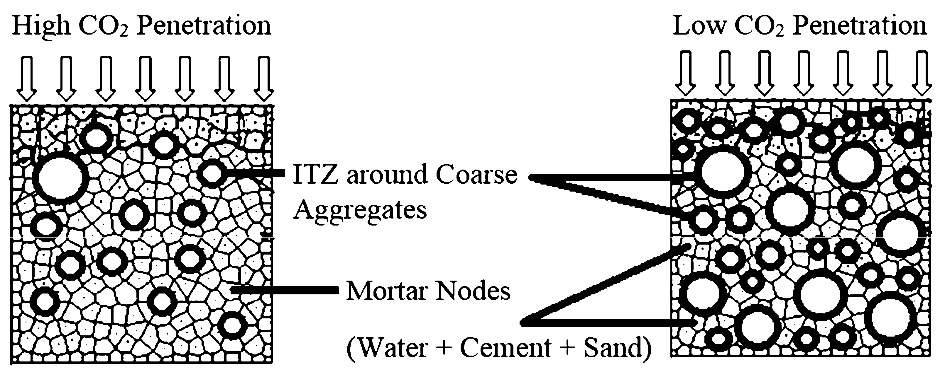
CO2 diffusion and carbonation reactions occur only in mortar, which consists of water, cement, and sand. This means that using less mortar or a coarser aggregate will decrease the carbonation depth. Carbonation depth is further decreased if small coarse aggregates are used, because they have a larger surface area thus providing a longer and more arduous path for CO2 diffusion Figure 2 [14]. Using small coarse aggregates with fine aggregates is preferable when designing durable concrete with ordinary Portland cement. While coarse aggregate grading does not affect the depth of carbonation, increasing the size of large coarse aggregates will increase the size and porosity of the interfacial transition zone, which may increase the carbonation depth. The interfacial transition zone is a thin shell between aggregate particles and hydrated cement paste, which significantly affects the permeability and durability of concrete [15].
A previous study showed that CO2 gas penetrates the concrete surface through the sand-cement connection gap [14]. This means that increasing the sand volume in concrete also increases CO2 penetration. However, another study revealed that increasing the sand volume of concrete reduces the water-to-cement ratio and makes the path of CO2 penetration more complex, thus reducing the depth of carbonation and air permeability [15].
Using graded fine aggregates in concrete retards CO2 penetration more than using only sand as a fine aggregate. In other words, graded aggregates help to delay CO2 penetration. In addition, applying thicker concrete covers or plastering covers delays CO2 penetration in RC structures, thereby extending the life of the passive film around steel bars [17].
1.2. Carbonation Depth with Time
Carbonation depth is one of the most important parameters when considering concrete damage [6,9,13]. As stated above, carbonation lowers the pH of concrete; therefore, measuring the low pH region of concrete can indicate carbonation depth. A commonly used method for measuring carbonation depth is to apply phenolphthalein (a pH indicator) spray on freshly fractured sections. The spray turns the section color from gray to dark pink if the pH has not been altered (i.e., the pH is around 13). Meanwhile, the color of the concrete does not change if the pH of the region is 8–9, thus indicating the carbonation depth [18,19,20].
Multiple factors contribute to carbonation depth, including the concentration of CO2 in the environment, relative humidity, and the type of cement. Table 1 highlights some of the major factors that control carbonation depth in field and laboratory environments. It can be seen that carbonation in concrete structures does not occur in isolation; induced or produced stresses, progressive changes within the concrete and the environment, inhomogeneity, and additives also contribute significantly to carbonation depth. CO2 enters concrete within a few hours of casting, and the depth of its penetration increases gradually [21].
Models used to measure carbonation depth can be modified according to the factors mentioned above; the simplest is that the carbonation depth (in mm) increases with the square root of the time (years). The rate of carbonation slows due to existing factors and factors that arise over time. CO2 easily diffuses through pores, but reactions with Ca(OH)2 are slow since they are gas-solid phase reactions. Continuous carbonation and hydration of concrete causes the sealing of micro-pores, which, in turn, hinders diffusion. As a result, the rate of CO2 diffusion decreases, thus slowing the carbonation rate [22,23,24].
Another method used to measure carbonation depth is microstructural analysis. CaCO3 is a chemical product formed during carbonation, and locating its presence in the depth profile via microstructural analysis can indicate the depth of the carbonation.
The contribution of carbonation to corrosion is similar to that of chloride corrosion, which decreases passivity and damages the passive layer. If the passive layer is not damaged, electron and ion transport across the passive layer remain limited. Once the passive layer is damaged, transport across the interface begins, and corrosion is initiated. Corrosion spreads as further physicochemical processes take place on the rebar surface.

Table 1.
Previous research on factors that control carbonation depth.
| Carbonation Depth | Environment | Major Findings | Research Focus |
|---|---|---|---|
| Depth increases with stress Carbonation depth increases | Lab exposure Natural exposure | Low load decreases carbonation, while high load increases carbonation. Unstressed structure life decreased by 1/3 under combined stress. | Flexural stress effect on carbonation [25] Stress effect on carbonation [26] |
| Carbonation time increases | Field exposure | More corrosion is needed to generate cracks on the surface. | Cover depth effect on carbonation-induced corrosion [27] |
| Carbonation depth varies | Recycled mixed concrete | Recycled coarse aggregate controls carbonation more effectively than nono-SiO2. | Inhomogeneities in carbonation depth recycled aggregate [28] |
| Carbonation depth decreases under sCO2 | Lab exposure | Among porosity, aggregate size, and their distribution, porosity in the interfacial transition zone makes the greatest contribution to carbonation | Interfacial transition zone changes under supercritical carbon dioxide [29] |
| Carbonation depth increases | Accelerated lab environment | Carbonation depth increases exponential function for temperature, power function for CO2, and polynomial function for relative humidity. | Carbonation depth as a function of temperature, humidity, and CO2 [24] |
| Carbonation depth decreases for BF slag | Natural carbonation | Among Portland cement, fly ash, and blast furnace slag, the latter yields the lowest uptake. | Changes in CO2 uptake due to different mineral additions [30] |
| Carbonation depth depends on additives | Natural and accelerated environment | It is hard to establish a correlation between lab-simulated and natural data. Only a simplistic model can be useful. | Carbonation modeling under normal and accelerated conditions [31] |
| Carbonation changes with temperature, humidity, and CO2 | Natural environment | Climatic changes (e.g., changes in CO2 concentration, humidity, and temperature) contribute to carbonation and induce damage. | Carbonation depth changes under climate changes [32] Climate change impact on faster CO2 ingress [33] |
| Uniform carbonation | Lab accelerated environment | Ambient pressure carbonation corrosion delays corrosion initiation. | Ambient pressure carbonation curing [34] |
| Carbonation increases | Accelerated carbonation | Carbonation decreases the strength of concrete and increases corrosion damage. | Accelerated carbonation testing in a sewage environment [35] |
| Corrosion increases with carbonation | Accelerated environment | Chloride penetration significantly increases with carbonation and crack size. | Combined impact of carbonation and crack width on chloride-assisted corrosion [36] |
| Carbonation depth increases with sulfates | Lab simulated environment | Sodium sulfate, which sometimes exists in slag materials, increases carbonation. | Sulfate-assisted carbonation [37] |
2. Corrosion of Concrete Structures
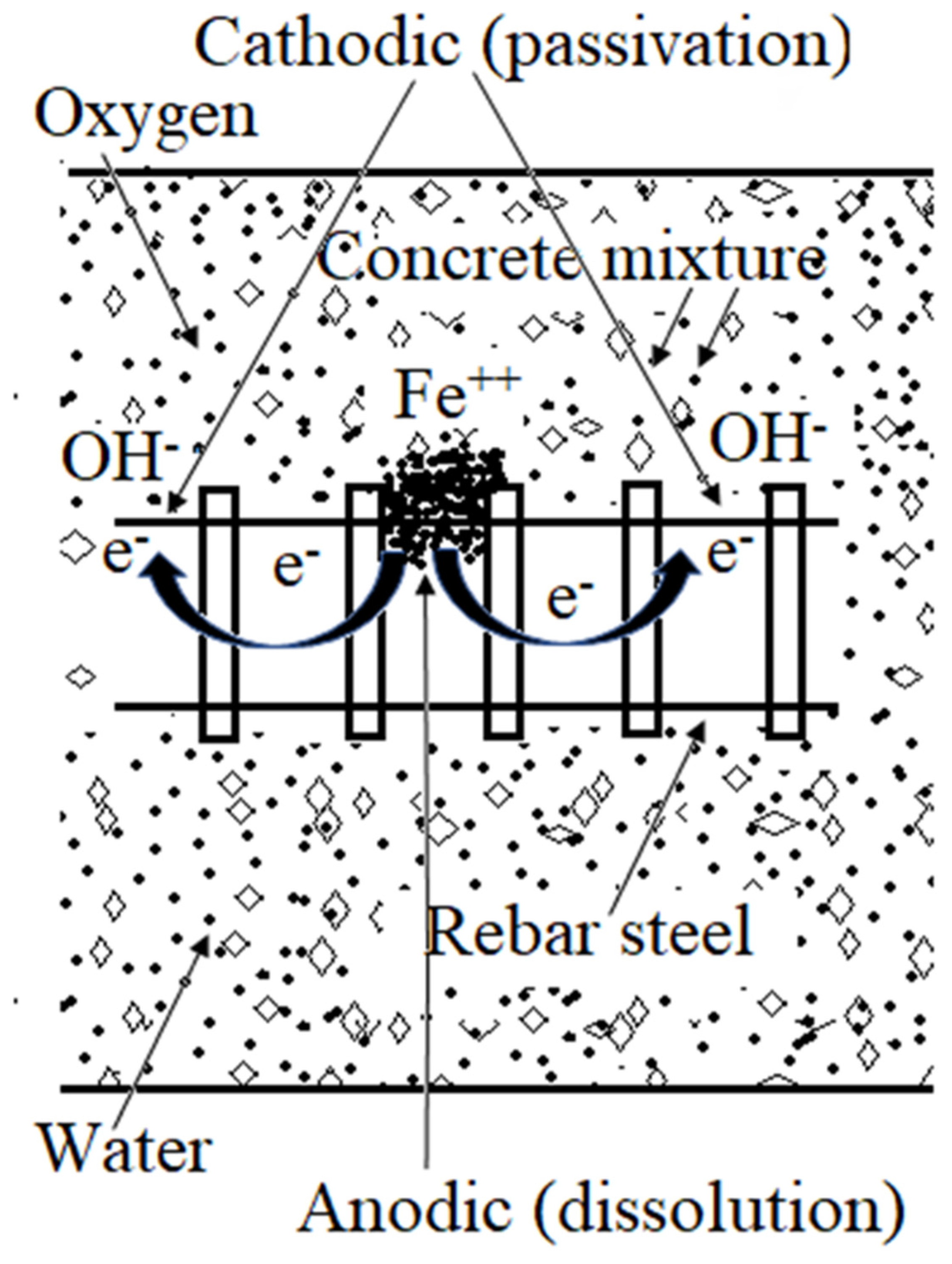
RC is a composite structure that acquires its high compressive strength from the ceramic matrix and its tensile strength from reinforced steel bars [38,39,40]. The compressive strength of an RC structure is compromised by carbonation, as mentioned in the previous section. The tensile strength of a concrete structure is reduced by the corrosion of its reinforced steel bars [41,42]. This corrosion is a multistep process that is initiated at the interface between the steel bars and mortar. The process of corrosion propagates due to oxide formation, which largely depends on the availability of oxygen and water at the concrete–steel bar infiltration interface [43,44]. Figure 3 shows the corrosion process in straightforward terms, indicating where localized anodic and cathodic reactions occur in the steel rebar. At anodic sites, iron converts into ions with the generation of electrons. These electrons travel through the steel bar to cathodic sites, where they interact with oxygen and water to generate OH−. Excess OH− ions aid the maintenance of high alkalinity at cathodic sites and foster corrosion at anodic sites. High alkalinity at cathodic sites breaks down the passive film and initiates cracking. The corrosion product formation is further directed to the area of major corrosion damage in the structure.
2.1. Steel Bar Corrosion in Concrete
The potential pH diagram, also known as a Pourbaix diagram, gives the first indication of corrosion for carbon steel in an aqueous solution with a pH value of 0–14. The pH level established in the concrete structure (approx. 13) allows a stable passive layer to form on the surface of the steel in the absence of dissolved chloride species [46]. Corrosion in metals consists of anodic and cathodic reactions. Metal ions or oxides are produced via an oxidation process, while hydrogen evolution and oxygen/water reduction are the most noticeable cathodic reactions. At a high pH, the dissolution of iron is balanced by hydroxyl ions, which form a stable passive film. If both reactions are balanced, corrosion will be very slow (if it occurs at all) [47,48].
Concrete structures’ porosity allows oxygen, water, and chloride species to infiltrate the steel bars embedded within concrete. Although carbonation does not directly contribute to corrosion, it does decrease the effective cover thickness of the concrete structure [49,50]. The porosity of concrete and the carbonation processes that occur allow reactive species to reach the steel bars and initiate corrosion due to the formation of microcells (anode and cathode). These microcells are initiated due to localized differences of potential (i.e., the potentials established for steel bars in concrete) and propagated due to differences in oxygen and ionic concentration (concentration cells). In this case, the anode and cathode are formed on the bars near to each other (in which case the corrosion cells are called microcells), causing the uniform corrosion of steel bars. If anodes and cathodes are far from each other, the corrosion cells are called macrocells, which cause predominantly localized corrosion [51].
2.2. Volume Expansion around Concrete Bars
The initiation of rebar corrosion is largely attributed to the breakdown of the passive film surrounding the rebar. Once this film breaks down, corrosion propagates due to the formation of the corrosion product, which consists of iron oxides. Oxide formation around the steel bar damages concrete either by thinning the rebar or generating stress around it. The rebar is thinned when iron is converted to iron oxide. This is because the formation of iron oxide decreases the effective cross-section of the rebar, hence increasing corrosion and decreasing the rebar’s strength. Oxide formation also increases the volume of the area around the bar, which generates stress. Although rebar thinning occurs very gradually, it weakens the structure by decreasing the available amount of metallic steel.
The conversion of iron into iron oxide increases the volume of the area around the bar by 2.2–6.4 times, depending on the type of oxide formed [29,30]. This increase in volume is enough to generate internal cracks in a porous concrete structure. The corrosion product accumulates over time, and internal cracks appear on the surface of the concrete due to the volume expansion effect. Once cracks appear on the surface, water, oxygen, and other reactive species can easily penetrate the rebar and cause significant damage.
3. Previous Research on Concrete Corrosion
3.1. Corrosion Mechanisms
Corrosion product analysis is a basic method for finding the species responsible for corrosion. In cases of concrete damage, a sample may be acquired for analysis by breaking up the structure near the rebar area and conducting a corrosion product analysis. This type of analysis was carried out by Smanta et al., who used multimodal neutron and X-ray tomography to characterize a corrosion product [52]. A sample was taken from a naturally corroded 81-year-old bridge structure, and compared with a galvanostatically polarized sample kept at a constant current in the laboratory. Qualitative and quantitative analyses were carried out to determine the depth of corrosion and the iron-to-rust ratio. They found that the corrosion product was approximately uniformly distributed around the rebar for galvanostatically polarized samples, while pits formed in naturally corroded samples (and the corrosion product was found in voids in the artificially polarized samples) [52].
The migration of the corrosion product was probably due to the highly corrosive nature of the NaCl solution and the polarization. Further chemical analysis of the corrosion product in voids may have authenticated the migration of corrosion product if hydrated iron oxide had been discovered. Although the presence of a soluble corrosion product has been reported by other researchers [21], there is a strong possibility of embedding the released product in the sample surface during grinding. The product obtained from the naturally corroded sample was similar to the product extracted from the lab-simulated (galvanostatically polarized) sample. The researchers reported an iron-to-rust ratio of 3.91–4.24, which suggests that ferrous and ferric hydroxides had formed. Other researchers also used X-ray and neutron tomography images to identify different phases present in RC structure, along with moisture content [53,54,55]. It can be difficult to precisely quantify phases, corrosion products, and water content using tomographic techniques alone; thus, analytic modeling may be employed to complement tomographic results.
A concrete structure used in wastewater treatment and in sewer conditions suffered a microbial attack, which led to the formation of bacterial colonies in pores and cracks [56]. Such a problem can be avoided by generating hydrophobicity or applying a fine deposition of an antibacterial coating, as impermeability and antibacterial coatings decrease the chances that bacterial colonies will form [57,58]. Yunchao et al. studied concrete’s resistance to microbial corrosion and reported that cetyltrimethylammonium bromide (CTAB) aided the electrodeposition of copper on hardened cement paste. They tested the sample using X-ray diffraction, scanning electron microscopy, Fourier transform infrared spectroscopy (FTIR), and a simulated microbial corrosion environment. The CTAB-assisted copper coating provided a protective layer smoother than a similar layer without CTAB, thus providing more resistance to microbiological corrosion [59]. Low concentrations of CTAB are associated with uniform and smooth copper coatings; the smooth copper coating restricted bacterial activity > 95% in an E-coli electrolyte. The formation of such a uniform and smooth layer is attributed to freely available nucleation sites, the number of which decreased as the CATB concentration increased [60,61].
Gabriel et al. tested the corrosion of concrete by measuring corrosion potential, galvanostatic polarization (constant current), and concrete cover resistance. They reported that corrosion potential at the surface of the rebar was significantly different to that of the concrete surface. This is attributed to mass electron transport processes that occur from the concrete cover to the rebar. The current density and corrosion rate were high for rebar with low coverage (i.e., where the thickness of the concrete was low). The higher corrosion rate may have been due to the easy infiltration of corrosive species into the rebar [62]. The researchers suggested that rebar spacing, concrete cover thickness, and rebar diameter significantly affected corrosion current and corrosion potential. The tests were carried out in three simulated environments, i.e., normal lab environment, in a chamber containing 50% CO2, and using concrete mixed with NaCl. Highest corrosion was observed for the NaCl samples, moderate for 50% CO2 chamber samples and the lowest for normal lab environment samples. This increasing corrosion trend is attributed to damage to the passive layer caused by carbonation and NaCl.
Hussein et al. tested whether the corrosion performance of concrete depends on whether ribbed or flat steel bars are used. They reported corrosion performance in terms of crack width, reduction in the cross-section of the rebar, and the loss of mechanical properties. They found that crack width and the presence of flexural cracks decreased the corrosion performance of the tested concrete structure [63]. The crack width profile of a concrete structure can be used to predict how much damage has been done, but it does not necessarily indicate the decrease in tension stiffness. Crack width increases over time due to corrosion activity and the localized generation of stress. Although the decrease in the cross-section area was the same for the ribbed rebar and the smooth rebar, ribbed rebar probably provided sites for the local concentration of stress, thus lowering the structure’s bending capacity.
The entry of chloride ions into the rebar environment causes a localized decrease in pH, which increases localized corrosion. Tristan et al. studied the initiation of corrosion as a function of chloride diffusion, finding that high concentrations of chloride ions at the surface sped up the initiation of the corrosion process [64]. The time required to initiate chloride-assisted corrosion can be shortened by up to 40% if the diffusion coefficient of chloride ions is restricted to less than 100 nm. Once chloride ions reach a threshold value, corrosion propagation begins. Chloride-assisted corrosion causes the de-passivation of steel bars, which leads to severe concrete damage.
The placement of a steel bar in the concrete, its height inside the mortar, and its orientation also contribute to its corrosion performance. Yuxin et al. tested the effects of these design parameters on corrosion by arranging steel bars vertically and horizontally, with different distances between the surface and the steel bar interface. They tested the specimens’ corrosion performance by providing wet and dry cycles and recording the open circuit potential. An autopsy test was carried out by collecting samples near the rebar areas and visualizing the defects. Many more defects (pores, cracks, and corrosion product accumulation) were identified in specimens with horizontally arranged steel bars than when the steel bars were arranged vertically [65].
Chloride ions significantly contribute to concrete corrosion, as the presence of chloride in the environment enhances corrosion propensity. Research on this matter was carried out by Fengyin et al., who compared naturally corroding structures in seawater with a structure potentiostatically polarized to 30 V in the same solution. A crack with a width of approximately 0.3 mm occurred in the naturally corroded sample after 700 days, while it took only 10 h for a crack of the same size to occur in the accelerated corrosion sample. The researchers attributed this fast corrosion to the migration of chloride ions, which was enhanced by the externally applied voltage [65]
Soil near the sea has high chloride content, which poses a severe threat to concrete structures in areas near the sea. Deqiang et al. compared corrosion in a soil environment with corrosion in seawater and in seawater containing a few sulfate ions. They reported that the threshold limit of saline soil is much higher than that of seawater. They also reported the inhibitory action of the small number of sulfate ions in the seawater environment [66].
A novel corrosion monitoring method based on electromagnetic sensors and acoustic emission sensors was carried out by Zhe et al. [67]. They developed sensors to record the activity produced inside concrete by the initiation and propagation of cracks. These sensors provided a non-destructive method for testing a concrete structure. The researchers conducted their experiment on stirrup- and longitudinal-reinforced bars in a simulated sea environment. Their results indicate that stirrup rebar structures suffer chloride corrosion much earlier than longitudinal rebar structures [68]. Other researchers have also used electromagnetic measurements, acoustic emission, and electrochemical sensors to monitor corrosion activity [68,69,70].
Measuring localized activity by non-destructive methods is a good option to detect a minute amount of damage before it propagates. During use of these methods, there is always a risk of noise signals from the surroundings which may easily lead to errors in the results, so caution should be observed during these non-destructive testing methods to minimize interruptions. The physical activity generated by localized stress can also be measured via insertion of a piezo-electric sensor to the closest proximity of the crack initiation sites. A small stress activity can be monitored in the form of voltage signals (piezo-electric material converts stress/pressure to voltage), which can subsequently be translated to corrosion activity.
Abbas et al. examined the combined effect of carbonation and chloride-induced corrosion by testing concrete specimens with different water-to-cement ratios and assessing their corrosion performance. Specimens with different ratios were first exposed to a CO2 environment and then to the accelerated corrosion environment. The results showed that corrosion potential and linear polarization parameters were higher (i.e., more corrosion occurred) for the pre-carbonated samples than for other samples. They also reported that carbonation and the width of cracks increased as the water-to-cement ratio of the concrete increased [37].
Although corrosion potential and linear polarization methods have been used extensively for measuring the corrosion damage in concrete, they are not very accurate. Multiple physicochemical processes take place in RC structures, e.g., water infiltration, oxygen diffusion, movement of chloride ions, crack generation and corrosion product formation. These corrosion processes which dictate the overall corrosion potential are capable of changing over time. Furthermore, during corrosion potential measurements or linear polarization measurements, counter electrodes and reference electrodes are kept far from the rebar. This does not provide exact measurements for certain readings, as some of the processes taking place in the concrete are left unaccounted for due to the highly resistive electrolytic environment of concrete.
Chen et al. conducted a field investigation alongside simulated laboratory experiments coupled with theoretical analyses. The field investigation involved recording corrosion potential, carbonation depth, and concrete resistivity. Meanwhile, laboratory tests were carried out to measure the chloride profile of the concrete, while the theoretical analyses were carried out using the Nernst equation and Butler-Volmer equation. The researchers revealed that none of the corrosion testing methods worked in isolation, as some of the field results needed to be supported by simulated results. The theoretical analyses that complemented the simulation added value to the results [71].
Wulong et al. studied stirrup rebar concrete under sustained loading, both with and without a chloride environment. They found that the horizontal legs of the RC beams corroded (as indicated by crack propagation and thickness of the corroding layer on the steel bars) primarily in the mid-span of the tensile zone and at the end of the compressive zone, regardless of the type of environment [72].
Xuhui et al. investigated corrosion-induced spalling and its effect on the shear strength of a concrete beam [73]. They used a mesoscale model to assess corrosion-induced spalling and a finite element model to link the corrosion damage, shear strength decrease, mechanical properties degradation, and mortar-to-rebar bond strength. They suggested that corrosion-induced spalling was initiated by inclined cracks in the rebar and was propagated diagonally towards the surface of the concrete. The crack propagation process worsened as corrosion of the rebar increased. The researchers also suggested that spalling is linked to cover thickness, stirrup spacing, and aggregate characteristics. Bond strength and damage to mechanical properties occurred only when the corrosion of the rebar increased significantly [73].
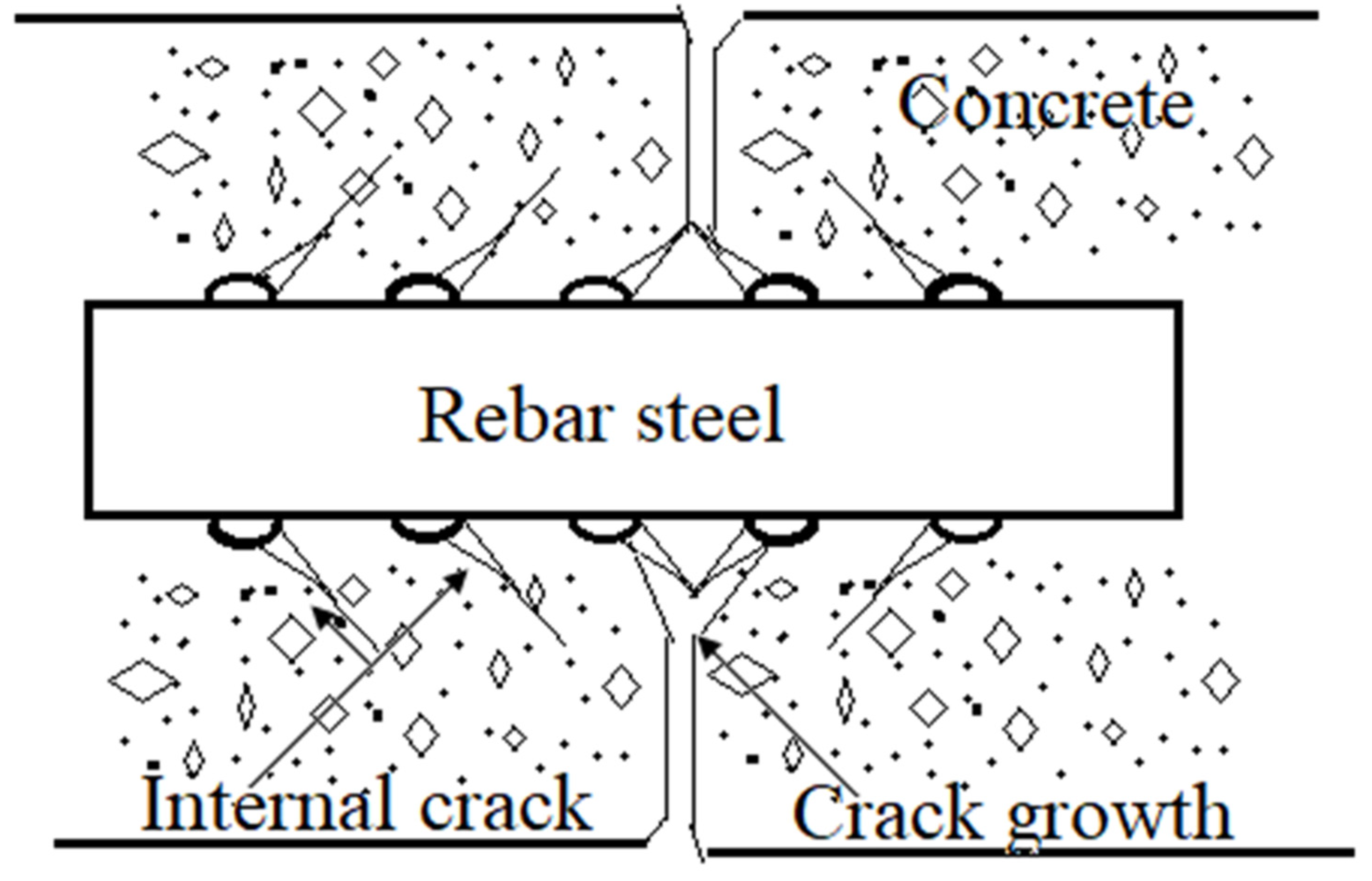
Figure 4 shows the cracking process in RC. Thin diagonal internal cracks initiate around the rebar steel when the corrosion process starts or when the passive layer breaks down. Upon increasing accumulation of corrosion product or the merging of cracks, the crack size further increases vertically towards the outside of the concrete surface. Once a crack emerges at the surface, major damage occurs due to the direct availability of oxygen to the rebar.
To reduce construction costs, Ditao et al. attempted to replace cement-based composite material with coral aggregate concrete [75]. Their concrete samples were made using ordinary Portland cement with coral sand and coral gravel with a particle size of 5–20 mm. The samples were electrochemically tested under forced chloride ion migration. Linear polarization resistance, electrochemical impedance spectroscopy, and scanning electron microscopy were used to determine the corrosion rate and to characterize the corrosion product. The corrosion results were later modeled with life expectancy; the coral aggregate concrete yielded higher values than commonly used concrete samples [75].
Hafiza et al. studied corrosion-induced cracking as a function of multidirectional rebars and cover thickness [76]. They performed an accelerated corrosion test on concrete samples with unidirectional or multidirectional rebars. They also changed the cover depth of the mortar on the steel rebar. The width of the crack and its growth rate depended significantly on the confined pressure developed by the corrosion product. The concrete with unidirectional rebars and that with multidirectional rebars were both affected by corrosion product pressure, but this effect was more pronounced in the latter case. According to the findings, when concrete is covered insufficiently, the pressure imposed on one rebar can generate cracks on an uncracked rebar. Furthermore, cracks on a transverse rebar stop cracks from forming in longitudinal rebars, thus hiding the damage within the structure, which may lead to sudden failure [76].
Accelerated corrosion tests of steel are very commonly reported in the literature exploring corrosion resistance parameters. For instance, Qiang et al. studied the effect of the wiring method on the corrosion of steel rebars. They carried out electrochemical tests for corrosion characterization, mechanical testing, and surface morphology on samples containing a single connection of stirrup and longitudinal rebar and four concoctions (between longitudinal and stirrups). Only the number of rust-induced cracks was different with the wiring, whereas crack width, corrosion rate, and other corrosion parameters were the same for both samples. Therefore, the wiring method does not directly affect rebar corrosion [77].
3.2. Corrosion Protection in Concrete by Inhibitors
Inhibitors are chemical species that are added in small amounts to a corrosion environment to restrict corrosion. Farshad et al. added carboxylate derivatives as corrosion inhibitors in concrete and characterized the inhibitors’ absorption on the surface using electrochemical impedance spectroscopy; they analyzed the corrosion product using X-ray photoelectron spectroscopy. The inhibitor dosage and effective time of the inhibitor were optimized, and it was found that the efficiency of the corrosion inhibitors was directly related to the attractive and repulsive forces generated at the surface of the rebar. When the concentration of the inhibitors was high, local clusters occurred at the surface, which caused the imperfect formation of a passive layer due to intermolecular forces between local molecules. This imperfect passive inhibitor layer, in turn, caused localized corrosion.
Pei Zhen et al. also studied corrosion protection by inhibition using a nitrite-based compound with a D-sodium gluconate inhibitor. They carried out electrochemical testing by electrochemical impedance spectroscopy and potentiodynamic polarization. The corrosion product analysis was carried out by XPs and AFM. The utilized inhibitor weakened the adsorption of chloride ions on the surface of the rebar, which stopped pitting corrosion and crack formation near the steel bars [78].
Youcef et al. used amine-based inhibitors in 0.5 M NaCl solution and carried out characterization using potentiodynamic polarization and impedance spectroscopy. The reported inhibitors were chemically adsorbed on the surface and decreased the corrosion rate without affecting the strength of the concrete [79].
Ashish et al. reported the effects of two generic inhibitors (i.e., triethyl phosphate and salicylaldehyde) in a chloride solution and found that they enhanced corrosion resistance [80]. They reported that an optimum dose of the inhibitors can improve corrosion resistance by more than 90%. The corrosion testing was carried out by potentiodynamic polarization, while the corrosion product analysis was carried out by X-ray photoelectron spectroscopy. Corrosion parameters (e.g., corrosion potential and current density) were higher in concrete samples with the inhibitor than in concrete samples without it. The corrosion product consisted of FeOOH, Fe2O3, and Fe3O4 [80].
Oxygen diffusion in a concrete structure contributes substantially to the propagation of corrosion. This effect of oxygen diffusion was indicated in the work of Dena et al., using a cellular automation framework. Oxygen diffusion was higher around the edges of the rebar than at the core of the rebar, which changed the corrosion potential and current density. The developed model fitted well with experimental and field data [81].
Researchers have tested whether adding inhibitors to concrete affects corrosion resistance, and inhibition in hardened concrete has not been reported. In one such work, Xiao et al. injected nitrite-based inhibitors under pressurized conditions into a hardened structure, finding that the cement-to-water ratio, inhibitor injecting pressure, and time taken to contain the pressure all affect the infiltration of inhibitors. As the water-to-cement ratio was increased, the inhibitor penetration depth increased, indicating effective corrosion protection [71].
In other work, Jie et al. explored the corrosion resistance performance of organic core-shell corrosion inhibitors. They used polystyrene-based inhibitors and ran tests using potentiodynamic polarization, impedance spectroscopy, and scanning electron microscopy. They found that the inhibitors were adsorbed by the rebar surface and formed complexes that slowed corrosion. Furthermore, they reported that these inhibitors were highly efficient even when concrete was exposed to corrosive media for long periods [82].
3.3. Corrosion Protection in Concrete by Coatings
Microbial corrosion is common in concrete structures in sewer environments or in the sea. Micro-organisms such as bacteria and algae may increase the corrosion rate. However, adding a thin layer of Cu2O to concrete can enhance the corrosion resistance of sewer structures. A study on this topic was carried out by Zhengyu et al., who coated concrete with a Cu2O layer and investigated samples using XRD, SEM, and X-ray photoelectron spectroscopy [83]. Cu2O-coated samples were tested in lab environments containing either sulfide reducing bacteria or sulfide oxidizing bacteria, and improvements were found under both conditions. The researchers observed good adhesion to the mortar but suggested further studies in sewer environments due to the complexity of such environments [83].
Deepak et al. achieved improved concrete corrosion performance by applying a fusion-bonded epoxy coating to the rebar; they also observed the coating’s effect on the type of corrosion mechanism [84]. They considered corrosion potential, linear polarization, and electrochemical impedance spectroscopy. Characterization of the corrosion product was carried out using scanning electron microscopy and energy-dispersive X-rays. The corrosion process in the coatings was best explained by impedance spectroscopy, which determined the corrosion initiation process more effectively than the other corrosion testing methods used in the study [84].
Abdulaziz et al. compared the corrosion performance of conventionally galvanized rebars and hot-dipped galvanized zinc-aluminum coatings [85]. A conventional zinc coating was modified by adding different percentages of aluminum. Corrosion testing was carried out using potentiodynamic polarization and impedance spectroscopy, while X-ray diffraction and Raman spectroscopy were employed for corrosion product analysis. The researchers suggested that zinc with the addition of 10% aluminum provides the optimum corrosion resistance by blocking reactive species from reaching the rebar [86].
Another study involving the surface modification of rebars to improve corrosion resistance was carried out by Liu et al., by applying a zinc phosphate conversion coating. The high corrosion resistance (as indicated by positive corrosion potential, low corrosion current, and high impedance values) was reported for the samples coated at 75 °C. Above this temperature, grain formation occurred, which increased porosity, allowing corrosion species to enter the rebar, thus increasing corrosion [86].
3.4. Corrosion Protection in Concrete by Cathodic Protection
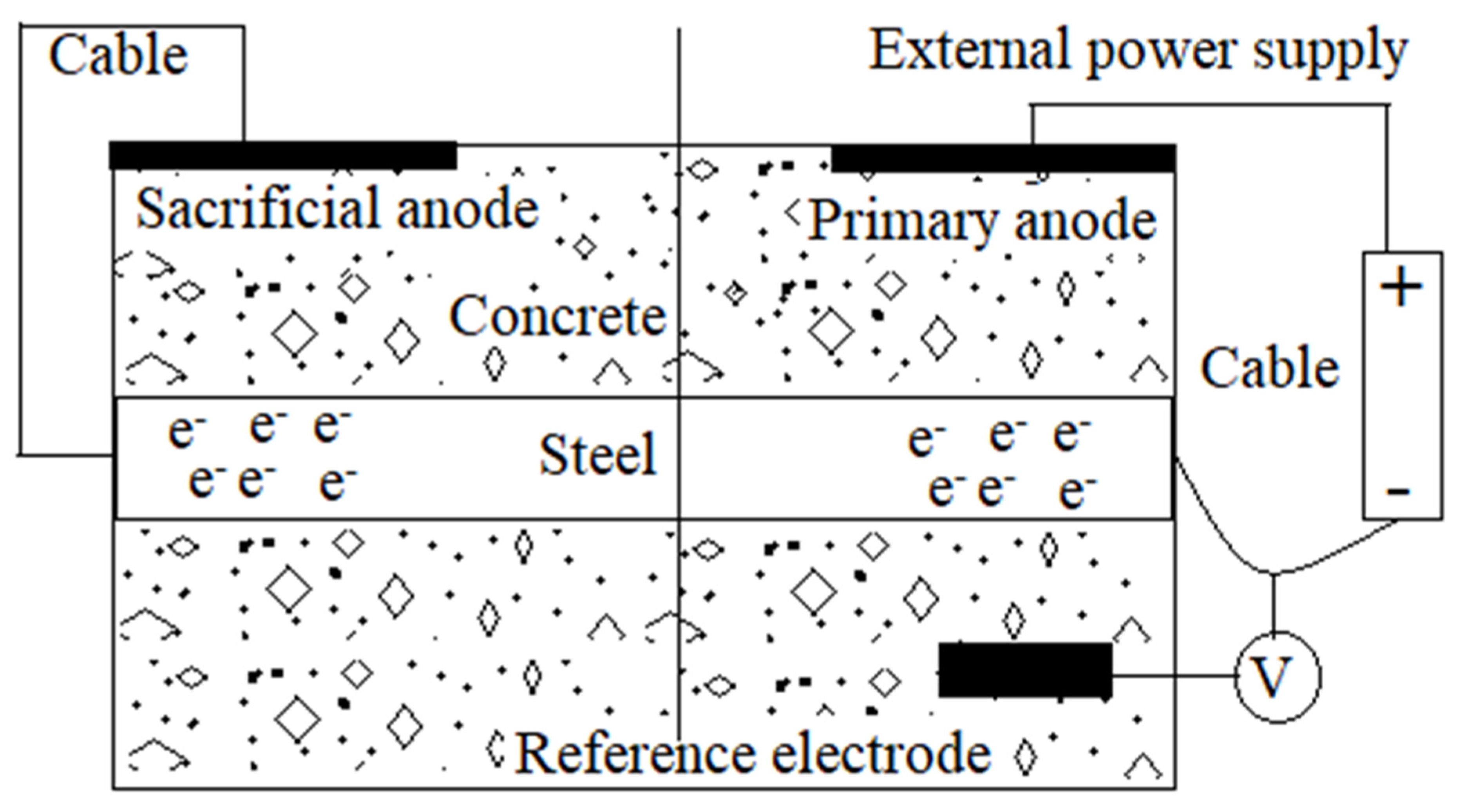
An important corrosion protection method used in concrete structures involves converting steel bars from anode to cathode. The desired current for cathodic protection is either provided by an external power source (impressed current cathodic protection) or by connecting the steel bars to an anodic material such as magnesium (sacrificial cathodic protection). Both methods are well-reported in the literature on the corrosion protection of concrete.
The schematic in Figure 5 shows sacrificial cathodic protection in which a reactive metal (e.g., magnesium or aluminum) provides the desired current to the rebar. The right-hand side of the schematic shows the impressed current method by which the current is supplied from an external source. A reference electrode is used to measure the potential between the rebar and the concrete mixture. The reference electrode helps establish and maintain the protection potential required during the cathodic protection process.
Zhang et al. used an impressed current cathodic in an RC structure [88], and found that concrete structures can be efficiently protected by the cathodic protection method, but that an excessive current can cause side effects in the form of acidification at the anode-concrete interface. The researchers prepared samples with different binders and tested them in an accelerated corrosion environment while implementing different current densities. The results showed that variations in current density and binder materials contribute significantly to degradation [88].
Parsad et al. studied the impressed current corrosion protection of a rebar structure by using a carbon fiber-reinforced polymer (CFRP) anode [89]. Impressed current cathodic protection was used on non-corroded samples and pre-corroded samples. The corrosion of the rebar structure at the optimized current density was estimated by recording the corrosion potential, corrosion rate, bond stress, and loss of mass. The researchers reported that the utilized carbon-fiber-reinforced polymer can provide efficient cathodic protection. They used different current densities and found that increasing the current density improved corrosion resistance (reported as stable corrosion potential and high polarization resistance). Furthermore, bond strength decreased as the protection current density increased [89].
Sacrificial cathodic protection is not commonly used in studies of concrete corrosion, though some researchers have used this method for short-term corrosion protection. For instance, Parthiban et al. used a magnesium alloy anode for cathodic protection in rebars in a chloride environment and found that the anode provided high negative potential on all surfaces. Furthermore, the uniform negative potentials across the surface indicate effective cathodic protection. The concentration of chloride infiltration was also low at different sites. The estimated effective cathodic protection period was three years; after this time, corrosion potential and chloride infiltration would change, indicating the initiation of corrosion [90].
Wang et al. investigated sacrificial cathodic protection using different anodes [91]. They simulated a corrosive environment in the lab using sacrificial anodes of aluminum, magnesium, and zinc alloys. The effectiveness of anodes was tested by recording the half-cell potential, electrochemical impedance spectroscopy, and titration analysis for chloride ions. These test results revealed that activity of the aluminum alloy anode ended much earlier than in the zinc and magnesium alloy anodes. The ineffectiveness of the aluminum anodes was probably due to the formation of alumina on the surface, preventing the further formation of ions and the release of electrons. Cathodic protection also aids the migration of chloride ions towards anodes, which increases the chloride content around the anode areas [91].
The throwing power of a rebar structure is important when determining the effectiveness of the cathodic protection method. Accordingly, Belleghem et al. carried out a study in which they recorded corrosion potential, polarization resistance, and galvanic corrosion over long periods under different environmental conditions [92]. Their results show that throwing power was highest during rainfall, when humidity was high, and when the temperature was low; throwing power decreased as the level of chloride content in the environment increased. They also reported that cathodic protection is more effective when it is implemented when corrosion is initiated [93]. The throwing power of localized anodes in concrete has also been reported to be effective under atmospheric conditions [92].
Although cathodic protection has been used extensively in concrete, its effectiveness depends on several parameters, including the electrical resistivity of the concrete, the distribution of current to the rebar structure, and protection potential. Arpit et al. examined the potential and current distribution in a cathodic protected concrete structure. They reported that 80% to 90% of the current density protects only the rebar near the surface of the concrete, while the lower part of the concrete is given very little protection. They also reported that the cathodic protection of a concrete structure depends heavily on the resistivity of the structure [94].
4. Discussion Summary
It can be concluded from the above discussion and review of previous empirical work that damage to concrete structures due to carbonation and corrosion is unavoidable. Although modifying the cement-to-water ratio and the design parameters of concrete can slow down the carbonation process, due to the porous structure of concrete and the availability of CO2 in the environment the process cannot be eliminated. Concrete is porous, which means it can be infiltrated by CO2 gas. Furthermore, the availability of CO2, the dry-wet cycle, relative humidity, and temperature cycles are all uncontrollable.
However, in general, using waterproofing additives (in liquid or powder form) can have a significant role in minimizing concrete porosity. In addition, low water content and the use of fine and coarse aggregate can retard CO2 penetration. These modifications in concrete can delay CO2 penetration for decades. A thick cover (minimum 4 cm) over the steel-bars contributes to delaying carbonation due to the long CO2-path from the environment to the passive layer. Moreover, using cladding, plastering or painting over reinforced concrete may completely prevent the penetration of CO2.
Carbonation depth does not directly contribute to corrosion, but it damages the passive layer, which initiates the corrosion process. The corrosion process is propagated due to the availability of active species e.g., chloride ions, sulfate ions and oxygen. Once corrosion propagates, differential oxygen cells and differential concentration cells establish inside the concrete. The differential oxygen cells create the potential gradient between the close proximity of the steel bar and the surrounding concrete environment. This potential gradient drives the electro-migration of active species including chloride ions towards the steel bar. These processes all together contribute to an environment which is very much conducive for pitting corrosion.
Furthermore, steel bars embedded in concrete structures can form oxides; while a layer can be added around steel bars to slow down corrosion, corrosion cannot be eliminated. The corrosion of concrete bars can be restricted by three methods: suppressing the anodic dissolution of the metal by providing a surplus of electrons, forming a metal oxide on the surface, and forming a barrier between environment and metal.
A surplus of electrons can be provided at the rebar by providing a precisely calculated current, which can be achieved using an external DC source or by connecting the rebar with more reactive material (e.g., magnesium or zinc). The process of providing a protective current via an external DC source is called impressed current cathodic protection; when the current is provided by a reactive metal, the process is called sacrificial cathodic protection. Researchers have explored both methods of cathodic protection, and found merits and demerits to its use. Although cathodic protection slows the corrosion process, it can impair the bond between the steel bar and the surrounding concrete. This decrease in the bond strength is attributed to the reduction of water around the steel bar, which causes the release of hydrogen, thus increasing pressure in the area.
The second significant problem with cathodic protection in concrete structures is the heterogeneity of the concrete environment. The surface of concrete is much more saturated with oxygen than the inside part, which generates differential oxygen concentration cells. While this contributes little to corrosion in new concrete, microcells formed due to variations in concentration gradient, moisture, and humidity do contribute noticeably to corrosion.
Corrosion inhibitors have been widely used to restrict the corrosion rate of concrete and have been reported to improve corrosion resistance by more than 90%. Inhibitors decrease corrosion either by adsorbing into the metal surface, blocking aggressive species from reaching the steel rebar surface, or slowing down their diffusion to the mortar-rebar interface. The main problems associated with the use of inhibitors are related to optimum dosage, inhibitor mixing, and inhibitor dose in hardened concrete. Other popular methods for restricting corrosion include modifying the concrete environment by enhancing alkalinity, combating chloride ions, and restricting oxygen diffusion. Furthermore, factors related to environment modification and inhibitor dose optimization can enhance the working life of a concrete structure.
Corrosion can also be resisted by coating steel rebars, for example, with thin Cu2O coatings. These coatings provide resistance to microbial corrosion, which is widespread in sea and sewage environments. Cu2O coatings provide a physical barrier that protects against the diffusion and infiltration of reactive species into the concrete, while also blocking the growth of micro-organisms that can severely damage concrete structures if they find a conducive environment for growth. Other metallic coatings (e.g., zinc and aluminum) can also be employed to protect rebars. Zinc and aluminum can be deposited as a thin oxide layer on rebars, as they adhere well to the surface of rebars. Furthermore, these coatings are not damaged by being submerged in concrete, which helps them slow down the initiation of corrosion. Fusion-bonded epoxy coatings stop the infiltration of water and oxygen into rebars, thus helping to avoid corrosion-related problems. While such coatings (which can be formed either on rebars or concrete) decrease corrosion problems, they add to the cost of construction. If necessary, a tradeoff can be made between bond strength, cost, and the working life of the concrete structure.
When ensuring the safety of a structure and determining its working life, it is important to carry out tests for carbonation depth, onset of rebar corrosion, rate of corrosion, concentration and depth of chloride ions, rebar mortar strength, and the overall strength of the RC structure. Different tests including chemical analysis, electrochemical measurement, flexural strength and compression strength measurement, and carbonation depth modeling have been applied according to the requirements of a certain aspect of the concrete, its properties, and the expertise of researchers. These include scanning electron microscopy to assess the microstructure of concrete, pore size, crack size and crack orientation. The onset of corrosion can be tested by various nondestructive methods, while the concrete strength and the strength of the bond between mortar and rebars can be assessed by destructive testing. Furthermore, X-ray diffraction and X-ray photo spectrometer analysis can be used to evaluate the passive layer.
Corrosion-induced damage to concrete can be qualitatively and quantitatively defined by electrochemical testing. The corrosion process occurs near the rebar due to electron transfer and mass transfer across the rebar and passive layer interface. Electron-driven reactions at the rebar surface cause anode and cathode regions to form. The mass transfer-driven reaction (oxygen diffusion and water infiltration) causes the reduction of oxygen and water, as well as the formation of corrosion products. This electron transfer process occurs inwards from the rebar, while the mass transfer process occurs outward to the solution side. Each reaction that takes place at the interface develops a potential difference, and the combined result of all reactions is called the equilibrium potential or corrosion potential. This potential can be measured using an electrode with a fixed potential (called a reference electrode). This corrosion potential can be measured in the rebar using a simple test. A positive and stable corrosion value indicates low corrosion, while a negative value indicates instability.
Direct current-based linear polarization and potentiodynamic polarization tests also provide some insight into the occurrence of corrosion at the interface. In linear polarization methods a low voltage window (−30 mV to 30 mV around open circuit potential) is provided around the cathodic and anodic region to determine the polarization resistance and corrosion rate. Although this test does not provide any details about localized corrosion, it does provide direct information about corrosion. The pitting propensity and stability of the passivity can be tested using a potentiodynamic test with a higher potential window for polarization. Electrochemical impedance spectroscopy is a detailed process for identifying different stages of corrosion from corrosion onset, water intake, passive layer damage, and major corrosion damage. Electrochemical impedance spectroscopy tests can be employed to study corrosion in detail, and the results of such tests can be compared with simulated models to make the results more meaningful.
Much effort has been made by researchers to establishing a correlation between the damage in natural field environments and in simulated laboratory environments. Furthermore, much data has been collected, but a precise correlation has not been identified. Additional in-depth studies are required to narrow this gap.
5. Conclusions
- The structure of the concrete in terms of its porosity, water-to-cement ratio, and aggregate size and distribution, significantly contributes to carbonation, as do environmental factors.
- Carbonation destroys the passive film of steel bars, but it does not corrode the bars.
- The initiation of corrosion can be studied by destructive and nondestructive methods.
- Cracks initiate horizontally by breaking down the passive film and then propagate vertically due to the volume expansion of the corrosion product around the rebar.
- Chloride ions are a major contributor to localized corrosion and damage to the passive layer.
- Protection methods can be applied as per the required service life of the RC structure. If a long service life is required, an effective protection method should be utilized.
- Corrosion protection can be achieved through cathodic protection, inhibitor addition, or the application of metallic or nonmetallic coatings, depending on the environment in which the concrete is built.
- Measurement of corrosion potential, linear polarization, potentiodynamic polarization, and electrochemical impedance spectroscopy can all be used for qualitative and quantitative corrosion analyses.
- Constituent analysis of the passive layer and corrosion product can be carried out by X-ray diffraction or X-ray photoelectron spectroscopy.
Author Contributions
A.F.A.F. reviewed the work on carbonation, and A.N. reviewed the concrete corrosion problem. All authors have read and agreed to the published version of the manuscript.
Funding
This work is supported by the Deanship of Scientific Research of King Faisal University under Grant No. AN000627.
Institutional Review Board Statement
Not applicable.
Informed Consent Statement
Not applicable.
Data Availability Statement
Not applicable.
Acknowledgments
The authors acknowledge the Deanship of Scientific Research of King Faisal University for financial support under the Annual Funding Track (Grant No. AN000627).
Conflicts of Interest
The authors declare that there is no conflict of interest.
References
- Stewart, M.G.; Wang, X.; Nguyen, M.N. Climate change impact and risks of concrete infrastructure deterioration. Eng. Struct. 2011, 33, 1326–1337. [Google Scholar] [CrossRef]
- Marques, P.F.; Chastre, C.; Nunes, Â. Carbonation service life modelling of RC structures for concrete with Portland and blended cements. Cem. Concr. Compos. 2013, 37, 171–184. [Google Scholar] [CrossRef]
- Aguiar, J.B.; Júnior, C. Carbonation of surface protected concrete. Constr. Build. Mater. 2013, 49, 478–483. [Google Scholar] [CrossRef] [Green Version]
- Park, D.C. Carbonation of concrete in relation to CO2 permeability and degradation of coatings. Constr. Build. Mater. 2008, 22, 2260–2268. [Google Scholar] [CrossRef]
- Šavija, B.; Luković, M. Carbonation of cement paste: Understanding, challenges, and opportunities. Constr. Build. Mater. 2016, 117, 285–301. [Google Scholar] [CrossRef] [Green Version]
- Marques, P.F.; Costa, A. Service life of RC structures: Carbonation induced corrosion. Prescriptive vs. performance-based methodologies. Constr. Build. Mater. 2010, 24, 258–265. [Google Scholar] [CrossRef]
- Neves, R.; Branco, F.; de Brito, J. Field assessment of the relationship between natural and accelerated concrete carbonation resistance. Cem. Concr. Compos. 2013, 41, 9–15. [Google Scholar] [CrossRef]
- Jiang, J.-Y.; Wang, D.; Chu, H.-Y.; Ma, H.; Liu, Y.; Gao, Y.; Shi, J.; Sun, W. The Passive Film Growth Mechanism of New Corrosion-Resistant Steel Rebar in Simulated Concrete Pore Solution: Nanometer Structure and Electrochemical Study. Materials 2017, 10, 412. [Google Scholar] [CrossRef] [Green Version]
- Marie-Victoire, E.; Cailleux, E.; Texier, A. Carbonation and historical buildings made of concrete. J. Phys. IV 2006, 136, 305–318. [Google Scholar] [CrossRef]
- Stewart, M.G.; Wang, X.; Nguyen, M.N. Climate change adaptation for corrosion control of concrete infrastructure. Struct. Saf. 2012, 35, 29–39. [Google Scholar] [CrossRef]
- Roy, S.K.; Northwood, D.O.; Poh, K.B. Effect of plastering on the carbonation of a 19-year-old reinforced concrete building. Constr. Build. Mater. 1996, 10, 267–272. [Google Scholar] [CrossRef]
- Huang, N.; Chang, J.; Liang, M. Effect of plastering on the carbonation of a 35-year-old reinforced concrete building. Constr. Build. Mater. 2012, 29, 206–214. [Google Scholar] [CrossRef]
- Talakokula, V.; Bhalla, S.; Ball, R.J.; Bowen, C.R.; Pesce, G.L.; Kurchania, R.; Bhattacharjee, B.; Gupta, A.; Paine, K. Diagnosis of carbonation induced corrosion initiation and progression in reinforced concrete structures using piezo-impedance transducers. Sens. Actuators A Phys. 2016, 242, 79–91. [Google Scholar] [CrossRef] [Green Version]
- Huang, Q.; Jiang, Z.; Zhang, W.; Gu, X.; Dou, X. Numerical analysis of the effect of coarse aggregate distribution on concrete carbonation. Constr. Build. Mater. 2012, 37, 27–35. [Google Scholar] [CrossRef]
- Basheer, L.; Basheer, P.A.M.; Long, A.E. Influence of coarse aggregate on the permeation, durability and the microstructure characteristics of ordinary Portland cement concrete. Constr. Build. Mater. 2005, 19, 682–690. [Google Scholar] [CrossRef]
- Jiang, Z.-L.; Gu, X.-L.; Huang, Q.-H.; Zhang, W.-P. Statistical analysis of concrete carbonation depths considering different coarse aggregate shapes. Constr. Build. Mater. 2019, 229, 116856. [Google Scholar] [CrossRef]
- Zhou, Y.; Gencturk, B.; Willam, K.; Attar, A. Carbonation-Induced and Chloride-Induced Corrosion in Reinforced Concrete Structures. J. Mater. Civ. Eng. 2014, 27, 04014245. [Google Scholar] [CrossRef]
- Elsalamawy, M.; Mohamed, A.; Kamal, E. The role of relative humidity and cement type on carbonation resistance of concrete. Alex. Eng. J. 2019, 58, 1257–1264. [Google Scholar] [CrossRef]
- Ferreira, M.; Jalali, S. Software for probability-based durability analysis of concrete structures. Concr. Repair Rehabil. Retrofit. 2005, 01, 117. [Google Scholar]
- Leemann, A.; Moro, F. Carbonation of concrete: The role of CO2 concentration, relative humidity and CO2 buffer capacity. Mater. Struct. 2016, 50, 30. [Google Scholar] [CrossRef]
- Jaffer, S.J.; Hansson, C.M. Chloride-induced corrosion products of steel in cracked-concrete subjected to different loading conditions. Cem. Concr. Res. 2009, 39, 116–125. [Google Scholar] [CrossRef]
- Czarnecki, L.; Woyciechowski, P. Prediction of the reinforced concrete structure durability under the risk of carbonation and chloride aggression. Bull. Pol. Acad. Sci. Tech. Sci. 2013, 61, 173–181. [Google Scholar] [CrossRef] [Green Version]
- Zhang, J.-s.; Cheng, M.; Zhu, J.-h. Carbonation Depth Model and Prediction of Hybrid Fiber Fly Ash Concrete. Adv. Civ. Eng. 2020, 2020, 9863963. [Google Scholar] [CrossRef]
- Liu, P.; Yu, Z.; Chen, Y. Carbonation depth model and carbonated acceleration rate of concrete under different environment. Cem. Concr. Compos. 2020, 114, 103736. [Google Scholar] [CrossRef]
- Wang, J.; Su, H.; Du, J. Influence of coupled effects between flexural tensile stress and carbonation time on the carbonation depth of concrete. Constr. Build. Mater. 2018, 190, 439–451. [Google Scholar] [CrossRef]
- Shi, X.; Yao, Y.; Wang, L.; Zhang, C.; Ahmad, I. A modified numerical model for predicting carbonation depth of concrete with stress damage. Constr. Build. Mater. 2021, 304, 124389. [Google Scholar] [CrossRef]
- Otieno, M.; Ikotun, J.; Ballim, Y. Experimental investigations on the influence of cover depth and concrete quality on time to cover cracking due to carbonation-induced corrosion of steel in RC structures in an urban, inland environment. Constr. Build. Mater. 2018, 198, 172–181. [Google Scholar] [CrossRef]
- Mi, R.; Pan, G. Inhomogeneities of carbonation depth distributions in recycled aggregate concretes: A visualisation and quantification study. Constr. Build. Mater. 2022, 330, 127300. [Google Scholar] [CrossRef]
- Bao, H.; Xu, G.; Yu, M.; Wang, Q.; Li, R.; Saafi, M.; Ye, J. Evolution of ITZ and its effect on the carbonation depth of concrete under supercritical CO2 condition. Cem. Concr. Compos. 2021, 126, 104336. [Google Scholar] [CrossRef]
- Younsi, A.; Turcry, P.; Aït-Mokhtar, A. Quantification of CO2 uptake of concretes with mineral additions after 10-year natural carbonation. J. Clean. Prod. 2022, 349, 131362. [Google Scholar] [CrossRef]
- Rathnarajan, S.; Dhanya, B.S.; Pillai, R.G.; Gettu, R.; Santhanam, M. Carbonation model for concretes with fly ash, slag, and limestone calcined clay-using accelerated and five-year natural exposure data. Cem. Concr. Compos. 2021, 126, 104329. [Google Scholar] [CrossRef]
- Chen, G.; Lv, Y.; Zhang, Y.; Yang, M. Carbonation depth predictions in concrete structures under changing climate condition in China. Eng. Fail. Anal. 2020, 119, 104990. [Google Scholar] [CrossRef]
- Al-Ameeri, A.S.; Rafiq, M.I.; Tsioulou, O.; Rybdylova, O. Impact of climate change on the carbonation in concrete due to carbon dioxide ingress: Experimental investigation and modelling. J. Build. Eng. 2021, 44, 102594. [Google Scholar] [CrossRef]
- Xian, X.; Zhang, D.; Lin, H.; Shao, Y. Ambient pressure carbonation curing of reinforced concrete for CO2 utilization and corrosion resistance. J. CO2 Util. 2021, 56, 101861. [Google Scholar] [CrossRef]
- Kong, L.; Han, M.; Yang, X. Evaluation on relationship between accelerated carbonation and deterioration of concrete subjected to a high-concentrated sewage environment. Constr. Build. Mater. 2019, 237, 117650. [Google Scholar] [CrossRef]
- Al-Ameeri, A.S.; Rafiq, M.I.; Tsioulou, O. Combined impact of carbonation and crack width on the Chloride Penetration and Corrosion Resistance of Concrete Structures. Cem. Concr. Compos. 2020, 115, 103819. [Google Scholar] [CrossRef]
- Liu, Z.; Hu, W.; Hou, L.; Deng, D. Effect of carbonation on physical sulfate attack on concrete by Na2SO4. Constr. Build. Mater. 2018, 193, 211–220. [Google Scholar] [CrossRef]
- Golewski, G.L. A novel specific requirements for materials used in reinforced concrete composites subjected to dynamic loads. Compos. Struct. 2019, 223, 110939. [Google Scholar] [CrossRef]
- Parameshwaran, R.; Naresh, R.; Ram, V.V.; Srinivas, P.V. Microencapsulated bio-based phase change material-micro concrete composite for thermal energy storage. J. Build. Eng. 2021, 39, 102247. [Google Scholar] [CrossRef]
- Babalola, O.E.; Awoyera, P.O.; Le, D.H.; Bendea Romero, L.M. A review of residual strength properties of normal and high strength concrete exposed to elevated temperatures: Impact of materials modification on behaviour of concrete composite. Constr. Build. Mater. 2021, 296, 123448. [Google Scholar] [CrossRef]
- Bicer, K.; Yalciner, H.; Pekrioglu Balkas, A.; Kumbasaroglu, A. Effect of corrosion on flexural strength of reinforced concrete beams with polypropylene fibers. Constr. Build. Mater. 2018, 185, 574–588. [Google Scholar] [CrossRef]
- Tapan, M.; Aboutaha, R.S. Effect of steel corrosion and loss of concrete cover on strength of deteriorated RC columns. Constr. Build. Mater. 2010, 25, 2596–2603. [Google Scholar] [CrossRef]
- Li, Z.; Jin, Z.; Wang, P.; Zhao, T. Corrosion mechanism of reinforced bars inside concrete and relevant monitoring or detection apparatus: A review. Constr. Build. Mater. 2021, 279, 122432. [Google Scholar] [CrossRef]
- Rodrigues, R.; Gaboreau, S.p.; Gance, J.; Ignatiadis, I.; Betelu, S.p. Reinforced concrete structures: A review of corrosion mechanisms and advances in electrical methods for corrosion monitoring. Constr. Build. Mater. 2020, 269, 121240. [Google Scholar] [CrossRef]
- Dhawan, S.; Bhalla, S.; Bhattacharjee, B. Reinforcement Corrosion in Concrete Structures and Service Life Predictions—A Review. In Proceedings of the 9th International Symposium on Advanced Science and Technology, New Delhi, India, 1–6 November 2014. [Google Scholar]
- Garcaos, P.; Saura, P.; Zornoza, E.; Andrade, C. Influence of pH on the nitrite corrosion inhibition of reinforcing steel in simulated concrete pore solution. Corros. Sci. 2011, 53, 3991–4000. [Google Scholar] [CrossRef]
- Xu, W.; Li, Y.; Li, H.; Wang, K.; Zhang, C.; Jiang, Y.; Qiang, S. Corrosion mechanism and damage characteristic of steel fiber concrete under the effect of stray current and salt solution. Constr. Build. Mater. 2021, 314, 125618. [Google Scholar] [CrossRef]
- Xu, X.; He, D.; Zeng, S.; He, W.; Tan, H.; Yu, Z. Effect of concrete cracks on the corrosion of headed studs in steel and concrete composite structures. Constr. Build. Mater. 2021, 293, 123440. [Google Scholar] [CrossRef]
- Akkaya, A.; Hakki, I. Investigation of the density, porosity, and permeability properties of pervious concrete with different methods. Constr. Build. Mater. 2021, 294, 123539. [Google Scholar] [CrossRef]
- Ridengaoqier, E.; Hatanaka, S.; Palamy, P.; Kurita, S. Experimental study on the porosity evaluation of pervious concrete by using ultrasonic wave testing on surfaces. Constr. Build. Mater. 2021, 300, 123959. [Google Scholar] [CrossRef]
- Chen, L.; Su, R.K.L. Corrosion rate measurement by using polarization resistance method for microcell and macrocell corrosion: Theoretical analysis and experimental work with simulated concrete pore solution. Constr. Build. Mater. 2020, 267, 121003. [Google Scholar] [CrossRef]
- Robuschi, S.; Tengattini, A.; Dijkstra, J.; Fernandez, I.; Lundgren, K. A closer look at corrosion of steel reinforcement bars in concrete using 3D neutron and X-ray computed tomography. Cem. Concr. Res. 2021, 144, 106439. [Google Scholar] [CrossRef]
- Roubin, E.; Andò, E.; Roux, S. The colours of concrete as seen by X-rays and neutrons. Cem. Concr. Compos. 2019, 104, 103336. [Google Scholar] [CrossRef] [Green Version]
- Dauti, D.; Tengattini, A.; Dal Pont, S.; Toropovs, N.; Briffaut, M.; Weber, B. Analysis of moisture migration in concrete at high temperature through in-situ neutron tomography. Cem. Concr. Res. 2018, 111, 41–55. [Google Scholar] [CrossRef]
- Zhang, P.; Liu, Z.; Wang, Y.; Yang, J.; Han, S.; Zhao, T. 3D neutron tomography of steel reinforcement corrosion in cement-based composites. Constr. Build. Mater. 2018, 162, 561–565. [Google Scholar] [CrossRef]
- Wu, H.; Li, Z.; Wang, Y.; Li, X.; Wang, F.; Zhu, W. Experimental Analysis of the Co-Deposition of Metal Cu and Nano-Sized SiC Particles with CTAB in Micro Via Filling. J. Electrochem. Soc. 2019, 166, D237–D243. [Google Scholar] [CrossRef]
- Mirghiasi, Z.; Bakhtiari, F.; Darezereshki, E.; Esmaeilzadeh, E. Preparation and characterization of CaO nanoparticles from Ca(OH)2 by direct thermal decomposition method. J. Ind. Eng. Chem. 2014, 20, 113–117. [Google Scholar] [CrossRef]
- Sadowski, Ł.; Hoła, J.; Czarnecki, L.; Mathia, T.G. New paradigm in the metrology of concrete surface morphology: Methods, parameters and applications. Measurement 2021, 169, 108497. [Google Scholar] [CrossRef]
- Liang, Y.; Chu, H.; Guo, M.-Z.; Zeng, Y.; Zhu, Z.; Jiang, L. CTAB-assisted electrodeposition of Cu coating on hardened cement paste for controlling microbial induced concrete corrosion. Constr. Build. Mater. 2021, 304, 124605. [Google Scholar] [CrossRef]
- Wilks, S.A.; Michels, H.T.; Keevil, C.W. Survival of Listeria monocytogenes Scott A on metal surfaces: Implications for cross-contamination. Int. J. Food Microbiol. 2006, 111, 93–98. [Google Scholar] [CrossRef]
- Song, Q.; Guo, M.-Z.; Wang, L.; Ling, T.-C. Use of steel slag as sustainable construction materials: A review of accelerated carbonation treatment. Resour. Conserv. Recycl. 2021, 173, 105740. [Google Scholar] [CrossRef]
- Samson, G.; Deby, F.; Garciaz, J.-L.; Lassoued, M. An alternative method to measure corrosion rate of reinforced concrete structures. Cem. Concr. Compos. 2020, 112, 103672. [Google Scholar] [CrossRef]
- Nasser, H.; Van Steen, C.; Vandewalle, L.; Verstrynge, E. An experimental assessment of corrosion damage and bending capacity reduction of singly reinforced concrete beams subjected to accelerated corrosion. Constr. Build. Mater. 2021, 286, 122773. [Google Scholar] [CrossRef]
- Senga Kiesse, T.; Bonnet, S.; Amiri, O.; Ventura, A. Analysis of corrosion risk due to chloride diffusion for concrete structures in marine environment. Mar. Struct. 2020, 73, 102804. [Google Scholar] [CrossRef]
- Cai, Y.; Zhang, W.; Yu, L.; Chen, M.; Yang, C.; Franasois, R.; Yang, K. Characteristics of the steel-concrete interface and their effect on the corrosion of steel bars in concrete. Constr. Build. Mater. 2020, 253, 119162. [Google Scholar] [CrossRef]
- Yang, D.; Yan, C.; Zhang, J.; Liu, S.; Li, J. Chloride threshold value and initial corrosion time of steel bars in concrete exposed to saline soil environments. Constr. Build. Mater. 2020, 267, 120979. [Google Scholar] [CrossRef]
- Li, Z.; Jin, Z.; Xu, X.; Zhao, T.; Wang, P.; Li, Z. Combined application of novel electromagnetic sensors and acoustic emission apparatus to monitor corrosion process of reinforced bars in concrete. Constr. Build. Mater. 2020, 245, 118472. [Google Scholar] [CrossRef]
- Sunny, A.I.; Tian, G.Y.; Zhang, J.; Pal, M. Low frequency (LF) RFID sensors and selective transient feature extraction for corrosion characterisation. Sens. Actuators A Phys. 2016, 241, 34–43. [Google Scholar] [CrossRef] [Green Version]
- Hong, S.; Wiggenhauser, H.; Helmerich, R.; Dong, B.; Dong, P.; Xing, F. Long-term monitoring of reinforcement corrosion in concrete using ground penetrating radar. Corros. Sci. 2017, 114, 123–132. [Google Scholar] [CrossRef]
- Caines, S.; Khan, F.; Zhang, Y.; Shirokoff, J. Simplified electrochemical potential noise method to predict corrosion and corrosion rate. J. Loss Prev. Process Ind. 2017, 47, 72–84. [Google Scholar] [CrossRef]
- Li, C.; Chen, Q.; Wang, R.; Wu, M. Corrosion assessment of reinforced concrete structures exposed to chloride environments in underground tunnels: Theoretical insights and practical data interpretations. Cem. Concr. Compos. 2020, 112, 103652. [Google Scholar] [CrossRef]
- Zhang, W.; Francois, R.; Wang, R.; Cai, Y.; Yu, L. Corrosion behavior of stirrups in corroded concrete beams exposed to chloride environment under sustained loading. Constr. Build. Mater. 2020, 274, 121987. [Google Scholar] [CrossRef]
- Zhang, X.; Zhang, Y.; Liu, B.; Liu, B.; Wu, W.; Yang, C. Corrosion-induced spalling of concrete cover and its effects on shear strength of RC beams. Eng. Fail. Anal. 2021, 127, 105538. [Google Scholar] [CrossRef]
- Piyasena, R. Crack Spacing, Crack Width, and Tension Stiffening Effect in Reinforced Concrete Beams and One-Way Slabs; Griffith University: Brisbane, Austria, 2003. [Google Scholar]
- Niu, D.; Zhang, L.; Fu, Q.; Wen, B.; Luo, D. Critical conditions and life prediction of reinforcement corrosion in coral aggregate concrete. Constr. Build. Mater. 2019, 238, 117685. [Google Scholar] [CrossRef]
- Zahid, H.F.; Jiradilok, P.; Kuntal, V.; Nagai, K. Investigation of the effects of multiple and multi-directional reinforcement on corrosion-induced concrete cracking pattern. Constr. Build. Mater. 2021, 283, 122594. [Google Scholar] [CrossRef]
- Li, Q.; Jin, X.; Yan, D.; Fu, C.; Xu, J. Study of wiring method on accelerated corrosion of steel bars in concrete. Constr. Build. Mater. 2020, 269, 121286. [Google Scholar] [CrossRef]
- Xu, P.; Zhou, J.; Li, G.; Wang, P.; Wang, P.; Li, F.; Zhang, B.; Chi, H. Corrosion inhibition efficiency of compound nitrite with D-sodium gluconate on carbon steel in simulated concrete pore solution. Constr. Build. Mater. 2021, 288, 123101. [Google Scholar] [CrossRef]
- Bellal, Y.; Benghanem, F.; Keraghel, S. A new corrosion inhibitor for steel rebar in concrete: Synthesis, electrochemical and theoretical studies. J. Mol. Struct. 2020, 1225, 129257. [Google Scholar] [CrossRef]
- Tiwari, A.; Goyal, S.; Luxami, V.; Chakraborty, M.K.; Prabhakar, G. Assessment of corrosion inhibition efficiency of generic compounds having different functional groups in carbonated pore solution with chlorides and migration ability in concrete. Constr. Build. Mater. 2021, 290, 123275. [Google Scholar] [CrossRef]
- Khatami, D.; Hajilar, S.; Shafei, B. Investigation of oxygen diffusion and corrosion potential in steel-reinforced concrete through a cellular automaton framework. Corros. Sci. 2021, 187, 109496. [Google Scholar] [CrossRef]
- Hu, J.; Zhu, Y.; Hang, J.; Zhang, Z.; Ma, Y.; Huang, H.; Yu, Q.; Wei, J. The effect of organic core–shell corrosion inhibitors on corrosion performance of the reinforcement in simulated concrete pore solution. Constr. Build. Mater. 2020, 267, 121011. [Google Scholar] [CrossRef]
- Zhu, Z.; Chu, H.; Guo, M.-Z.; Zhang, Y.; Song, Z.; Jiang, L. Anti-microbial corrosion performance of concrete treated by Cu2O electrodeposition: Influence of different treatment parameters. Cem. Concr. Compos. 2021, 123, 104195. [Google Scholar] [CrossRef]
- Kamde, D.K.; Pillai, R.G. Corrosion initiation mechanisms and service life estimation of concrete systems with fusion-bonded-epoxy (FBE) coated steel exposed to chlorides. Constr. Build. Mater. 2021, 277, 122314. [Google Scholar] [CrossRef]
- Al-Negheimish, A.; Hussain, R.R.; Alhozaimy, A.; Singh, D.D.N. Corrosion performance of hot-dip galvanized zinc-aluminum coated steel rebars in comparison to the conventional pure zinc coated rebars in concrete environment. Constr. Build. Mater. 2020, 274, 121921. [Google Scholar] [CrossRef]
- Liu, J.; Zhang, B.; Qi, W.H.; Deng, Y.G.; Misra, R.D.K. Corrosion response of zinc phosphate conversion coating on steel fibers for concrete applications. J. Mater. Res. Technol. 2020, 9, 5912–5921. [Google Scholar] [CrossRef]
- Polder, R.; Peelen, W.H.A. Cathodic protection of steel in concrete–experience and overview of 30 years application. MATEC Web Conf. 2018, 199, 01002. [Google Scholar] [CrossRef]
- Zhang, E.Q.; Abbas, Z.; Tang, L. Predicting degradation of the anode–concrete interface for impressed current cathodic protection in concrete. Constr. Build. Mater. 2018, 185, 57–68. [Google Scholar] [CrossRef]
- Bahekar, P.V.; Gadve, S.S. Impressed current cathodic protection of rebar in concrete using Carbon FRP laminate. Constr. Build. Mater. 2017, 156, 242–251. [Google Scholar] [CrossRef]
- Parthiban, G.T.; Parthiban, T.; Ravi, R.; Saraswathy, V.; Palaniswamy, N.; Sivan, V. Cathodic protection of steel in concrete using magnesium alloy anode. Corros. Sci. 2008, 50, 3329–3335. [Google Scholar] [CrossRef]
- Wang, F.; Xu, J.; Xu, Y.; Jiang, L.; Ma, G. A comparative investigation on cathodic protections of three sacrificial anodes on chloride-contaminated reinforced concrete. Constr. Build. Mater. 2020, 246, 118476. [Google Scholar] [CrossRef]
- Redaelli, E.; Lollini, F.; Bertolini, L. Throwing power of localised anodes for the cathodic protection of slender carbonated concrete elements in atmospheric conditions. Constr. Build. Mater. 2012, 39, 95–104. [Google Scholar] [CrossRef]
- Van Belleghem, B.; Maes, M.; Soetens, T. Throwing power and service life of galvanic cathodic protection with embedded discrete anodes for steel reinforcement in chloride contaminated concrete. Constr. Build. Mater. 2021, 310, 125187. [Google Scholar] [CrossRef]
- Goyal, A.; Olorunnipa, E.K.; Pouya, H.S.; Ganjian, E.; Olubanwo, A.O. Potential and current distribution across different layers of reinforcement in reinforced concrete cathodic protection system—A numerical study. Constr. Build. Mater. 2020, 262, 120580. [Google Scholar] [CrossRef]
Figure 1.
Carbonation assisted by water and CO2 adsorption [5].
Figure 1.
Carbonation assisted by water and CO2 adsorption [5].

Figure 2.
The effects of mortar and coarse aggregate contents on a concrete mixture’s carbonation resistance [16].
Figure 2.
The effects of mortar and coarse aggregate contents on a concrete mixture’s carbonation resistance [16].

Figure 3.
The corrosion process in reinforced concrete [45].
Figure 3.
The corrosion process in reinforced concrete [45].

Figure 4.
Initiation and propagation of cracks in reinforced concrete [74].
Figure 4.
Initiation and propagation of cracks in reinforced concrete [74].

Figure 5.
Cathodic protection process by the sacrificial anode and impressed current methods [87].
Figure 5.
Cathodic protection process by the sacrificial anode and impressed current methods [87].

Publisher’s Note: MDPI stays neutral with regard to jurisdictional claims in published maps and institutional affiliations. |
© 2022 by the authors. Licensee MDPI, Basel, Switzerland. This article is an open access article distributed under the terms and conditions of the Creative Commons Attribution (CC BY) license (https://creativecommons.org/licenses/by/4.0/).
Share and Cite
MDPI and ACS Style
Fuhaid, A.F.A.; Niaz, A. Carbonation and Corrosion Problems in Reinforced Concrete Structures. Buildings 2022, 12, 586. https://0-doi-org.brum.beds.ac.uk/10.3390/buildings12050586
AMA Style
Fuhaid AFA, Niaz A. Carbonation and Corrosion Problems in Reinforced Concrete Structures. Buildings. 2022; 12(5):586. https://0-doi-org.brum.beds.ac.uk/10.3390/buildings12050586
Chicago/Turabian StyleFuhaid, Abdulrahman Fahad Al, and Akbar Niaz. 2022. "Carbonation and Corrosion Problems in Reinforced Concrete Structures" Buildings 12, no. 5: 586. https://0-doi-org.brum.beds.ac.uk/10.3390/buildings12050586
Note that from the first issue of 2016, this journal uses article numbers instead of page numbers. See further details here.