Article

Integrated Schematic Design Method for Shear Wall Structures: A Practical Application of Generative Adversarial Networks

1
Beijing Engineering Research Center of Steel and Concrete Composite Structures, Tsinghua University, Beijing 100084, China
2
Key Laboratory of Civil Engineering Safety and Durability of Ministry of Education, Tsinghua University, Beijing 100084, China
3
Central-South Architectural Design Institute Co., Ltd., Wuhan 430071, China
4
Beijing Institute of Architectural Design Co., Ltd., Beijing 100045, China
*
Author to whom correspondence should be addressed.
Submission received: 14 July 2022 / Revised: 16 August 2022 / Accepted: 22 August 2022 / Published: 24 August 2022
(This article belongs to the Special Issue Intelligent and Computer Technologies Application in Construction)

Abstract

:
The intelligent design method based on generative adversarial networks (GANs) represents an emerging structural design paradigm where design rules are not artificially defined but are directly learned from existing design data. GAN-based methods have exhibited promising potential compared to conventional methods in the schematic design phase of reinforced concrete (RC) shear wall structures. However, for the following reasons, it is challenging to apply GAN-based approaches in the industry and to integrate them into the structural design process. (1) The data form of GAN-based methods is heterogeneous from that of the widely used computer-aided design (CAD) methods, and (2) GAN-based methods have high requirements on the hardware and software environment of the user’s computer. As a result, this study proposes an integrated schematic design method for RC shear wall structures, providing a workable GAN application strategy. Specifically, (1) a preprocessing method of architectural CAD drawings is proposed to connect the GAN with the upstream architectural design; (2) a user-friendly cloud design platform is built to reduce the requirements of the user’s local computer environment; and (3) a heterogeneous data transformation method and a parametric modeling procedure are proposed to automatically establish a structural analysis model based on GAN’s design, facilitating downstream detailed design tasks. The proposed method makes it possible for the entire schematic design phase of RC shear wall structures to be intelligent and automated. A case study reveals that the proposed method has a heterogeneous data transformation accuracy of 97.3% and is capable of generating shear wall layout designs similar to the designs of a competent engineer, with 225 times higher efficiency.

1. Introduction

Intelligent structural design is an essential aspect of the fourth industrial revolution in the architecture, engineering, and construction (AEC) sector [1,2,3]. A reinforced concrete (RC) shear wall structure is an effective lateral force-resistant structural system commonly employed in high-rise residential buildings and is an important research object in intelligent structural design [4,5]. Schematic design is the first step in the structural design of RC shear-wall structures, which mainly involves the spatial layout of the primary force-transmitting components, including shear walls and beams. It is an essential basis for subsequent detailed design tasks and significantly impacts the final design outcomes [6].
Currently, the schematic design is usually manually completed by experienced engineers, resulting in low design efficiency and high labor costs. Existing intelligent schematic design methods can generally be separated into rule-based and learning-based methods [7,8]. Rule-based methods rely significantly on user-defined design rules, which tend to be less effective for complex real-world problems. Additionally, the length of time they require (usually several hours to dozens of hours) hinders their application in the industry. In contrast, learning-based methods do not require artificially defined explicit design rules but can automatically discover and master design laws from existing design data. Moreover, they have the advantage of extremely high design efficiency in the application stage [8,9]. As a typical representative of learning-based methods, generative adversarial networks (GAN)-based methods have recently made substantial strides in intelligent structural design. Existing studies have shown that GAN-based methods can effectively learn from existing design data and efficiently complete structural designs. The overall performance of the structures designed by GANs is close to that of structures designed by engineers [10,11,12,13,14].
However, several obstacles prevent existing GAN-based methods from being effectively applied in the industry. (1) GANs are based on computer vision techniques, and their inputs are in the form of pixel images. Consequently, GANs cannot directly perform structural designs based on the architectural computer-aided design (CAD) drawings commonly used in the industry. (2) GANs have a high requirement in terms of the computer environment. In terms of software, a deep learning framework and dependent libraries are needed. In terms of hardware, a graphics processing unit (GPU) is needed to achieve high design efficiency. (3) The outputs of GAN-based methods are also pixel images, where structural design-related information is unstructured data, making it challenging to establish the structural analysis model required for subsequent detailed design tasks.
This study focuses on the above research gaps and proposes a systematic solution, i.e., an integrated schematic design method based on GAN, as shown in Figure 1. First, a preprocessing method for architectural CAD drawings is proposed. Second, a cloud design platform is built based on the concept of software as a service (SaaS). Third, a high-precision data transformation method is proposed for transforming pixel images into structured data. Subsequently, a parametric modeling procedure is constructed to establish the structural analysis model. The proposed method can be easily embedded in the existing structural design process and can automatically complete the schematic design task traditionally manually finished by engineers. It should be noted that, at present, the structural designs are mainly stored in the form of 2D CAD drawings in China, and mainstream building information modeling software (e.g., Revit) supports exporting 3D models into 2D drawings. Therefore, this study takes 2D CAD drawings as the input of the structural design workflow.
The remainder of this study is organized as follows. Section 2 is the literature review. Section 3 presents the framework of the integrated schematic design method. Section 4 introduces the preprocessing method of architectural CAD drawings. Section 5 introduces the intelligent design method based on GANs. Section 6 introduces the heterogeneous data transformation method and the parametric modeling procedure. A typical case study using the proposed method is presented in Section 7. Finally, conclusions are drawn in Section 8.

2. Literature Review

2.1. Learning-Based Structural Design Method

In recent years, machine learning has been extensively applied in the AEC sector [2]. As a novel paradigm, the machine learning-based structural design method has attracted substantial attention [7,8,9]. Compared with traditional rule-based methods, it can automatically discover and master design rules from existing design data without artificially defining them. Additionally, once the machine learning model is trained, it has the advantage of extremely high design efficiency. For example, Almasabha et al. [15] used several machine learning algorithms in the design of shear links for steel buildings; Zheng et al. [16] adopted artificial neural networks to speed up the topological design of shell structures; and Chang and Cheng [17] applied graph neural networks in the structural optimization of framed structures.
More recently, breakthroughs have been made in structural design methods using computer vision techniques, particularly GANs [18]. A GAN consists of a generator and a discriminator, where the generator strives to generate real-looking designs to fool the discriminator, and the discriminator tries to discriminate between real and fake designs. In a game between the two, the generator can learn to generate realistic designs after Nash equilibrium is reached. Liao et al. [10] and Pizarro et al. [11] effectively applied GANs to the shear wall layout design. Liao et al. [12] further proposed a “fused-text-image-to-image” GAN to consider the influence of design conditions on an intelligent structural design. Zhao et al. [13] expanded the applicability of GANs to the beam–slab system of shear wall residential buildings. Liao et al. [10] and Zhao et al. [13] evaluated the structural design performance of GANs using the intersection over union (IoU) of model-generated and engineer-designed structural pixel images. However, this evaluation method measures unstructured pixel-by-pixel consistency, which is not equivalent to the structural layout consistency on which the schematic design task focuses. Meanwhile, the performance of solely data-driven GANs depends on the quality and quantity of the training data, which limits their applications [10,12]. Consequently, Lu et al. [14] further embedded physical mechanisms into GANs and proposed a physics-enhanced GAN for the shear wall layout design. The physics-enhanced GAN features better interpretability, and its performance is less affected by training data. However, the inputs and outputs of the above method are still in the form of pixel images, limiting its embedment in the existing structural design process.

2.2. Parametric Modeling

Parametric modeling is a crucial tool for automated structural design, which can significantly improve design efficiency [19] and potentially benefit design creativity [20]. Existing studies have offered various parametric design systems that can automatically search for optimal solutions by combining optimization algorithms with parametric models [21,22,23,24]. However, these methods require structured design data as input and are difficult to apply to the unstructured design data obtained by GAN-based methods.

2.3. Transformation between Pixel Image and Structured Design Data

The input and output of the GAN-based method are unstructured pixel images, but structured design data are commonly used in the structural design process. In practical applications, it is necessary to convert the structured design data (architectural CAD drawing) into an architectural pixel image (GAN’s input) and then convert the structural pixel image (GAN’s output) into structured design data (structural analysis model). Pizarro and Massone [25] proposed a method to extract the polygons of wall contours from architectural CAD drawings, but the error rate was around 15%, requiring manual inspection and correction. To establish the structural analysis model from the structural pixel image, Lu et al. [14] proposed a vectorization method for pixel images of shear walls, but the accuracy was unsatisfactory, resulting in errors and missing elements frequently. Therefore, there is still a lack of high-precision preprocessing and heterogeneous data transformation methods for GAN-based methods.

3. Framework

The proposed integrated schematic design method based on GAN for RC shear wall structures is shown in Figure 2. It can complete structural design and establish structural analysis models according to the architectural CAD drawings and design conditions within 10 min, accomplishing the intelligent and automated design of RC shear wall structures. The proposed method includes the following modules.
(1)
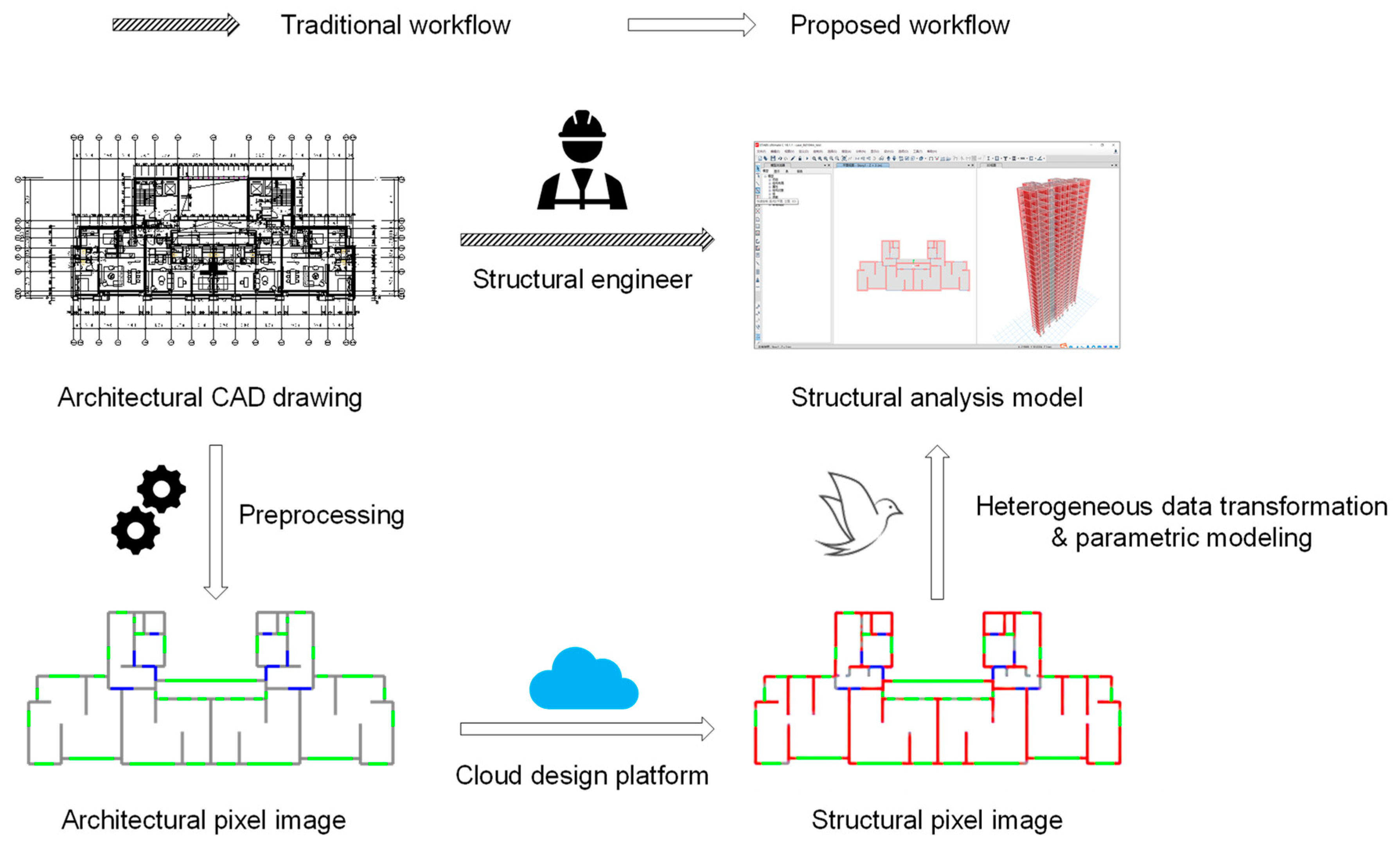
Preprocessing of architectural CAD drawings: Figure 2a shows the extraction of architectural elements using the AutoCAD plugin GANIO developed based on the AutoCAD application programming interface (API) using C# [26]. GANIO can automatically identify and extract essential architectural elements (i.e., partition walls, doors, and windows) and output their coordinates. Engineers can also check and adjust the extraction results through human–computer interaction. Subsequently, the architectural pixel image can be generated based on the architectural element coordinates. This process requires approximately 5 min.
(2)
Generation of structural schematic design: Figure 2b shows the cloud design platform developed based on SaaS, which can swiftly generate a schematic design of the shear wall structure. After the architectural pixel image is uploaded, the cloud platform inputs it into the pre-trained GAN deployed on the cloud server. The GAN generates the corresponding structural pixel image in seconds and outputs it to the cloud platform for users to download. This process requires approximately 1 min.
(3)
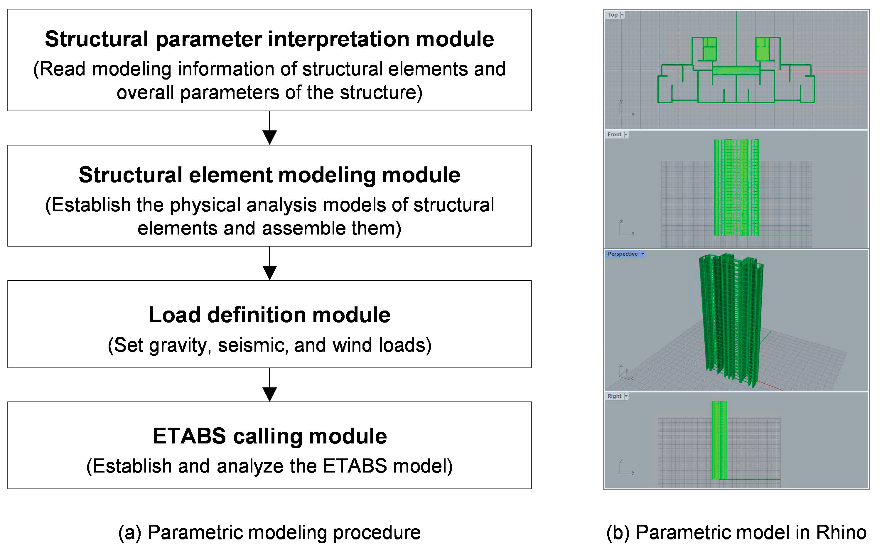
Establishment of structural analysis model: Figure 2c shows the automatic modeling from the pixel image to the structural analysis model. First, identify and extract the key structural elements in the structural pixel image and obtain their coordinates. Next, utilize the parametric modeling software Swallow (ESD) [27], developed based on the Grasshopper API, to import structural element coordinates and establish a parametric model according to a predetermined modeling procedure. Finally, export the parametric model to ETABS for structural analysis. This process requires approximately 2 min.
It should be noted that the floor area affects the time consumption of the preprocessing of architectural CAD drawings and the establishment of a structural analysis model. Their time consumption mentioned above is based on a common RC shear wall structure with a floor area of around 500 m2. The time consumption of the generation of structural schematic design is affected by the hardware performance and bandwidth of the cloud server. Its time consumption mentioned above is based on a common cloud server equipped with one Intel ® Xeon ® E5-2682 v4 CPU (two cores, 2.5 GHz), one NVIDIA P4 GPU (8 GB), and a bandwidth of 1 Mbps.

4. Preprocessing of Architectural CAD Drawings

Architectural CAD drawings contain numerous elements, as shown in Figure 2a. However, the elements related to structural design are sparse, mainly including three categories: partition walls (where shear walls can be positioned), doors, and windows (where shear walls cannot be positioned) [10,14]. To enable deep neural networks to extract the key features of architectural design and avoid the influence of irrelevant data, Liao et al. [10] proposed an architectural design representation method using semantic pixel images, extracting the key elements in the architectural CAD drawing and representing their categories with different colors in the RGB pixel image. However, manually completing these operations is inefficient, prone to errors, and unrealistic for industrial applications. Therefore, this study develops a CAD plugin, GANIO, based on the AutoCAD API [26], which can automatically extract and output the axis coordinates of critical elements. The coordinates are also used in Section 6.1 for the automatic identification and extraction of shear walls in semantic structural pixel images.
Specifically, the user interface of the GANIO plugin, depicted in Figure 3a, has three major functions: parameter setup, axis extraction, and coordinate export. The first step involves setting up six parameters. The first three are the maximum wall thickness, minimum wall thickness, and minimum wall length. These parameters are the thresholds for determining whether an element is a partition wall. The remaining three parameters are the layer names of the partition wall, door, and window. GANIO extracts the corresponding elements from a specified layer. The second step is to select the target elements and click on the “Extraction” button. GANIO locates key elements by matching parallel lines, calculates the coordinates of their axes, and draws the axes on a new layer. Engineers can check and adjust the extracted axes using an AutoCAD user interface. The third step is to select the extracted axes and click on the “Export” button. The axis coordinates of the key architectural elements are exported in a readable text format. Finally, according to the coordinates and categories of the key elements, Python-OpenCV is used to represent the key elements as RGB pixel images, as shown in Figure 3b. Distinct categories of elements are represented by different colors: the partition wall is gray (RGB = (132, 132, 132)), the door is blue (RGB = (0, 0, 255)), and the window is green (RGB = (0, 255, 0)).

5. Intelligent Structural Design Based on GANs

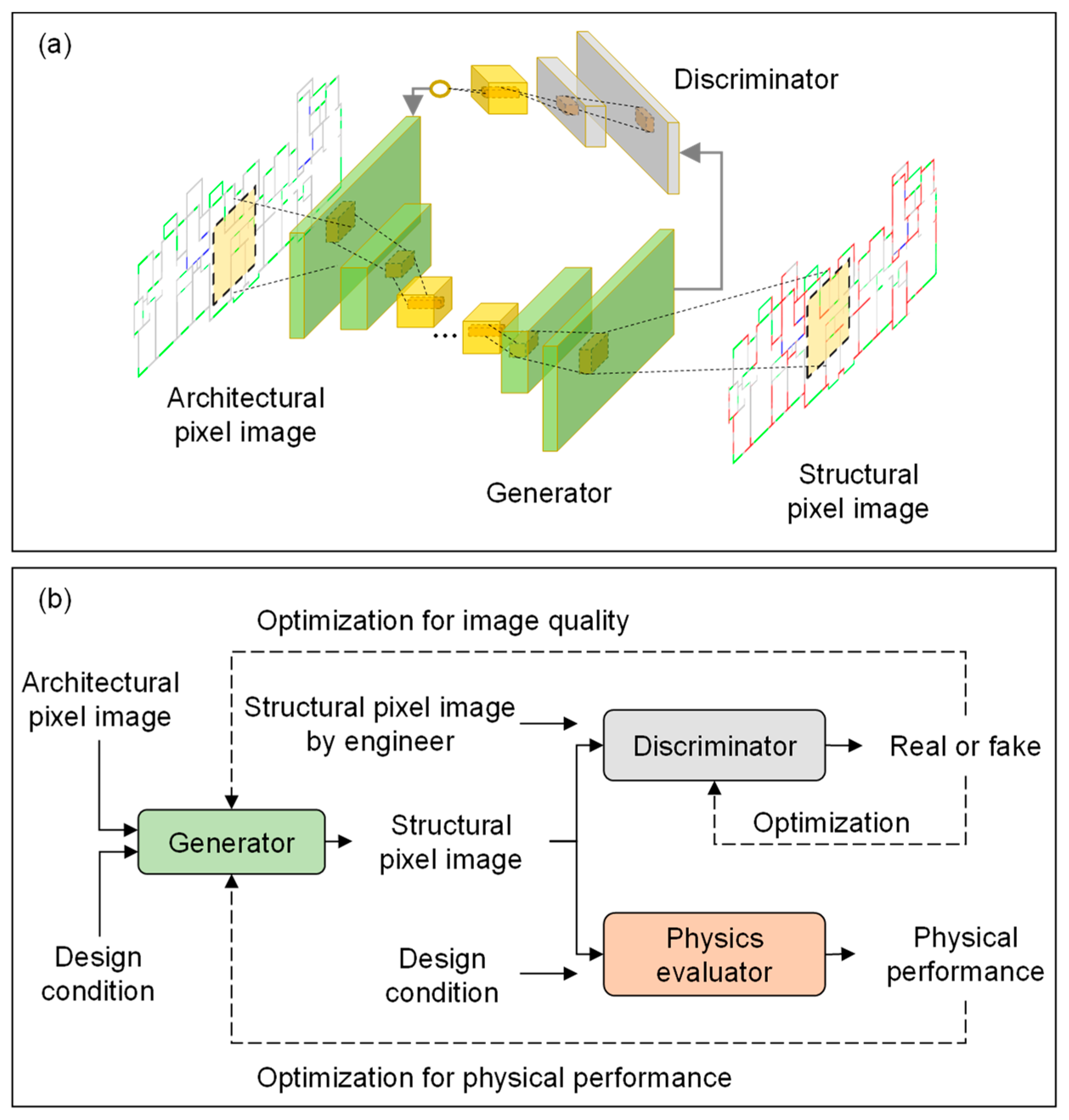
5.1. Physics-Enhanced GAN

Experience and mechanics are two indispensable aspects of structural design. This study adopts the physics-enhanced GAN proposed by Lu et al. [14] (referred to as StructGAN-PHY) to generate the structural schematic design. The architecture of a conventional data-driven GAN is shown in Figure 4a (referred to as StructGAN), which only comprises a generator and a discriminator [10]. The architecture of StructGAN-PHY is shown in Figure 4b. Apart from a generator and a discriminator, StructGAN-PHY also comprises a physics evaluator. The generator generates a structural design according to the architectural design and design conditions. The discriminator judges whether the generated structural design is real or fake and forms an image loss L G img , which is fed back to the generator to improve the image quality of its designs. Meanwhile, the physics evaluator predicts the physical performance of the generated structural design considering the design conditions and forms a physics loss L G PHY , which is fed back to the generator to improve the physical performance of its designs. The loss functions of the generator and discriminator are shown in Equations (1) and (2), respectively. The generator, discriminator, and physics evaluator work together in the training stage until the model performance is stabilized and the Nash equilibrium is reached.
L G = ω img L G img + ω PHY L G PHY ,
L D = L D GAN ,
where L G img is the image loss, as shown in Equation (3); L G PHY is the physics loss predicted by the physics evaluator; ω img and ω PHY are the weights of L G img and L G PHY , respectively [14]; is the discriminator loss [28].
L G img = L G GAN + λ FM ( L G FM + L G VGG ) ,
where L G GAN , L G FM , and L G VGG are different types of image losses and λ FM is the weight [10,28].
The physics evaluator is a surrogate model based on neural networks, which can output the physics loss of a generated structural design corresponding to its physical performance. For details, please refer to Lu et al. [14]. For RC shear wall structures, the inter-story drift under earthquakes is a critical indicator that reflects their physical performance, which can be evaluated by P drift as shown in Equation (4). The physical loss predicted by the physical evaluator is an approximation to P drift .
P drift = { 1 d max d limit , d max d limit ( d max d limit 1 ) 0.5 , d max > d limit ,
where d max is the maximum inter-story drift; d limit = 0.001 is the drift limit specified by the Chinese design code [29].

5.2. Dataset

This study collects 159 sets of architectural and structural CAD drawings and their design conditions from 10 top architectural design institutes in China. The collected CAD drawings have been used in real-world construction projects. Before that, they had been comprehensively optimized by the engineers to guarantee that all design code requirements were fulfilled. Therefore, the CAD drawings have a high design quality. The preprocessing method described in Section 4 is adopted to extract the coordinates of partition walls, doors, and windows from architectural CAD drawings and obtain corresponding architectural pixel images. Similarly, the coordinates of the shear walls are extracted from the structural CAD drawings, and the corresponding structural pixel images are obtained. One hundred thirty-five sets of architectural pixel images and their corresponding structural pixel images are used as the training set. Then, the training set is enlarged four times through data augmentation (flipping and mirroring). The remaining 24 sets of architectural pixel images are used as the test set, and their corresponding structural pixel images are not visible to the GAN. Typical architectural and structural pixel images and their design conditions (seismic intensity and structural height) are shown in Figure 5.
Although the dataset is small in comparison to other deep learning tasks, it is effective for the training of StructGAN-PHY for the following reasons. (1) The focus of this research is on common shear wall structures in residential buildings. StructGAN-PHY can effectively learn general design rules from a relatively small dataset because the structures to be designed are in similar forms. (2) Key structural design elements are extracted from CAD drawings and processed into semantic pixel images. It is easier for StructGAN-PHY to learn from the preprocessed semantic images, and therefore fewer data are needed. (3) The incorporation of the physics mechanism reduces the model’s reliance on data even further. (4) Data augmentation is used to increase the size of the training set.

5.3. Cloud Design Platform

Using StructGAN-PHY as the core algorithm, this study develops a cloud design platform based on the concept of SaaS, as illustrated in Figure 6. The cloud platform provides software services for users, with minimum requirements for users’ local hardware and software, and the design process is straightforward and efficient. The client provides a human–computer interaction interface, including project creation, file upload, project design, and result download functions. The server is used to handle client requests and manage user data. All computing and design processes are performed on a GPU-powered server.
(1)
Client: Figure 6a shows the homepage of the cloud platform, which has a login entry, manual, technical support, version history, and introduction to the technical details of the core algorithm. Figure 6b shows the window for creating a new project, including inputting the project name, uploading the architectural pixel image, selecting the design conditions (i.e., seismic intensity and structural height), and inputting the scale (unit: mm/pixel). The seismic intensity can be selected among 6 degrees (0.05 g), 7 degrees (0.10 g), 7 degrees (0.15 g), 8 degrees (0.20 g), 8 degrees (0.30 g), and 9 degrees (0.40 g). The numbers in brackets represent the seismic design acceleration with an exceedance probability of 10% in 50 years. The structural height can be selected as <40, 40–60, 60–80, 80–100, and >100 m. Figure 6c shows the project list. The initial status of a project is “to be converted”. Clicking the “Convert” button calls the pre-trained StructGAN-PHY deployed on the server for the design. The obtained design result is a structural pixel image (Figure 6d), where red (RGB = (255, 0, 0)) represents the shear wall layout. This pixel image can be downloaded by the user for subsequent parametric modeling.
(2)
Server: The Python, Flask, and Nginx environments are set up on a Windows system. The website front-end is developed based on HTML and CSS, where Flask-login is adopted for the login interface management. The database for user data management adopts PyMySql, and data can be delivered by Flask-sqlalchemy. The website backend is developed based on Python, where the PyTorch deep learning framework and its dependent libraries are installed to run the pre-trained StructGAN-PHY model. Furthermore, Nginx builds network services, connecting the client and the server.

6. Establishment of the Structural Analysis Model

6.1. Heterogeneous Data Transformation

Based on Lu et al. [14], this study proposes a heterogeneous data transformation method that considers architectural design information, as shown in Figure 7. This method involves the following steps:
Step 1: Extract shear wall pixels
First, the RGB pixel image is expressed in the HSV color. Second, the red pixels (i.e., shear walls) are stripped from the structural pixel image and binarized. Subsequently, the corrosion (cv2.erode()) and dilation (cv2.dilate()) functions in Python-OpenCV are used to remove the noise in the binary image. Finally, a binary pixel image of the shear walls is obtained.
Step 2: Extract shear wall axes
Based on the assumption that the shear walls can only be positioned at the location of the partition walls, the intersection points between the axis of the partition wall and the contour of the shear wall pixels in the binary image are searched pixel-by-pixel and used as the endpoints of the axis of the shear wall. All axes of the partition walls are traversed to complete the extraction of the shear wall axes.
Step 3: Assign frame and coupling beams
The axes of the partition walls, doors, and windows are collectively called the architectural axes. It is assumed that (1) beams are only positioned on architectural axes and (2) coaxial shear walls are connected by coupling beams. First, assign the beams over the architectural axes, excluding the positions where the shear walls are already positioned. Subsequently, check the topological relationship of the beams, delete cantilever beams, and confirm that both ends of the beams are connected to the shear walls or other beams.
Note that GAN-based methods focus on common residential buildings so that general design rules can be learned from existing design data. Therefore, the assumptions described in Step 3 are generally acceptable. If the assumptions are not applicable, the beam layout obtained with the proposed method might be unreasonable, resulting in inaccurate structural analysis results. However, in the schematic design phase of RC shear wall structures, the beam layout is less crucial than the shear wall layout. Additionally, inaccuracy in the structural analysis model is acceptable because it can be corrected in the subsequent detailed design phase by optimization algorithms or manual adjustments to fulfill special requirements.
Based on the above steps (Figure 7), the axis coordinates of the shear walls, frame beams, and coupling beams are derived. Furthermore, the shear wall thickness is estimated according to the empirical law proposed by Lu et al. [14]. The section heights of the frame and coupling beam can also be determined according to the empirical law presented by Qian et al. [4] as 1/12 and 1/8 of the beam span, respectively. The axis coordinates and section dimensions of the shear walls, frame beams, and coupling beams are used as the input data for the parametric modeling. Based on the initial structural layout and section size, subsequent adjustments and optimizations can be easily accomplished using a parametric model.

6.2. Parametric Modeling

Parametric modeling is a digital modeling method that builds structural models from input data according to predefined rules, thereby realizing real-time mapping between input data and structural models. By leveraging the human–computer interaction interface developed via visual programming, users can modify the structural design and corresponding model in real-time. Rhino and its Grasshopper plugin are the commonly used parametric modeling platforms in the industry, but they lack professional structural analysis capabilities. In this study, Swallow (ESD), a parametric modeling plugin for building structures based on Grasshopper, is used as a bridge between the Grasshopper and structural analysis software (e.g., ETABS) [27]. Using Swallow (ESD), structural properties can be defined in Grasshopper, and structural analysis models can be assembled. ETABS can be called in real-time through the ETABS API for structural analysis, and the analysis results of ETABS can be viewed.
Figure 8a demonstrates the parametric modeling procedure based on Swallow (ESD), and the final parametric model is shown in Figure 8b. (1) Firstly, the structural parameter interpretation module is built to read the axis coordinates and section sizes of structural components generated in Section 6.1; to convert them into structured data required for the modeling of shear walls, coupling beams, and frame beams; and to read the overall parameters of the structure specified by the user, including the story height and the number of stories. (2) Subsequently, the structural element modeling module is built to model shear walls and coupling beams using shell elements, model frame beams using beam elements, and model slabs using membrane elements; to define the properties of the material, section, and element; and to assemble all structural elements to complete the structural analysis model. (3) Next, a load definition module is built to distribute beam-end loads according to the structural layout and set seismic and wind loads according to the seismic and wind design requirements. (4) Finally, an ETABS calling module is constructed to complete the establishment and analysis of the ETABS model by calling the ETABS API.

7. Case Study

7.1. Evaluation Method of Shear Wall Layout

The schematic design of RC shear wall structures focuses on the shear wall layout. This study uses the IoU of the shear wall axes to evaluate the consistency of the model-generated and engineer-designed planar layouts, which is more reasonable than the IoU of pixel images [10,13]. Meanwhile, the shear wall layout significantly influences the vertical load-transfer mechanism of the floor system. A reasonable shear wall layout can effectively hold the slabs so that they are uniformly stressed [30]. Therefore, this study uses the supported floor ratio to evaluate the vertical load transferability of slabs. In addition, with the help of structural analysis models, the physical performance of the designed structure is also evaluated.
(1)
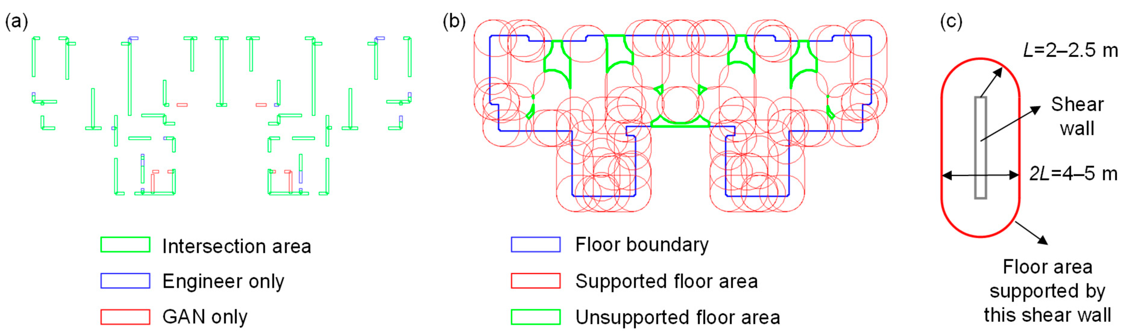
Planar layout consistency
The heterogeneous data transformation method described in Section 6.1 is utilized to obtain the coordinates of the shear walls designed by the GAN. Subsequently, the shear wall planar layout is drawn as a set of rectangles, and the intersection and union areas of the GAN’s and the engineer’s designs are calculated. Furthermore, the difference between the total length of the shear walls designed by the GAN and the engineer is calculated as a correction coefficient. Figure 9a shows the calculation of the intersection and union areas, where green represents the intersection area, blue represents the exclusive part of the engineer’s design, and red represents the exclusive part of the GAN’s design. The union area is a combination of green, red, and blue colors. The modified planar layout consistency indicator S IoU M can be calculated using Equations (5) and (6).
S IoU M = η DiffSwall A inter A union ,
η DiffSwall = 1 | L GAN L ENG | L ENG ,
where A inter and A union are the intersection and union areas of the shear walls designed by the GAN and the engineer, respectively; η DiffSwall is the correction coefficient for the difference in total shear wall length; and L GAN and L ENG are the total lengths of the shear walls designed by the GAN and the engineer, respectively.
(2)
Vertical load transferability
The vertical load transferability is assessed by the floor area supported by the shear walls, as shown in Figure 9b. First, the floor boundary (blue contour) is obtained; then, the floor area that each shear wall can support (red contour) is calculated, as shown in Figure 9c [30]. Furthermore, all the supported floor areas are subtracted from the floor area. Finally, the unsupported floor areas (green contours) are obtained, and the supported floor ratio under the vertical load ( S FloorA ) is obtained based on the ratio of the green area to the blue area, as indicated in Equation (7).
S FloorA = 1 A minus A floor ,
where A minus is the floor area that is not supported by the shear walls, and A floor is the total area of the floor.
Figure 9. Evaluation method of shear wall layout: (a) planar layout consistency; (b) vertical load transferability; (c) floor area supported by a shear wall.
Buildings 12 01295 g009
(3)
Physical performance under horizontal seismic load
After the ETABS model is established, a refined structural analysis can be performed to evaluate the physical performance of the structure. For example, the inter-story drift under earthquakes is a critical indicator in evaluating the lateral resistance capacity of RC shear wall structures. Equation (8) calculates the consistency of the inter-story drifts of the structures designed by the GAN and the engineer.
S IDR = 1 ( | 1 θ GAN , X θ ENG , X | + | 1 θ GAN , Y θ ENG , Y | ) / 2 ,
where θ GAN , X and θ GAN , Y are the maximum inter-story drifts of the GAN’s design in the X and Y directions, respectively, and θ ENG , X and θ ENG , Y are the maximum inter-story drifts of the engineer’s design in the X and Y directions, respectively.

7.2. Basic Information of a Typical Case

This case study is based on a typical residential building in northern China. The building has a structural height of 96 m and 30 stories. It is lower than 100 m and is classified as a common high-rise building. Its floor has a bounding area of 41.2 m × 17.7 m (around 500 m2). The seismic intensity is 8-degree, corresponding to a 0.20 g seismic design acceleration with an exceedance probability of 10% in 50 years. This seismic design acceleration a is medium-level (0.05 g ≤ a ≤ 0.40 g). The characteristic site period Tg is 0.55 s, which is also medium-level (0.2 s ≤ Tg ≤ 0.9 s). The architectural CAD drawing, corresponding pixel image, and structural design by the engineer are shown in Figure 10a–c, respectively.

7.3. Detailed Analyses of a Typical Case

The building was designed using the proposed integrated design method. The structural pixel image downloaded from the cloud design platform (i.e., the output of the StructGAN-PHY model) is shown in Figure 11a, and the details in the black dashed box are shown in Figure 11b. Two heterogeneous data transformation methods, one proposed by Lu et al. [14] and another proposed in this study, were used to convert the structural pixel image into structured data. The results are compared in Figure 11c,d. Lu et al.’s method [14] results in the absence of several short shear walls and an undesirable offset of the shear wall axes, which is adverse for the subsequent modeling task. The proposed method prevents these problems and accurately extracts nearly all shear walls. In this case study, the StructGAN-PHY lays out a total of 73 shear walls. Lu et al.’s method [14] correctly extracted 44 shear walls with an accuracy of 60.3%. The proposed method correctly extracted 71 shear walls with an accuracy of 97.3%. The accuracy therefor increases significantly by 37.0%. It should be noted that the above results are obtained from the typical case study in Section 7.2.
The design of the proposed integrated method is evaluated using the methods described in Section 7.1. The evaluation results are shown in Figure 12 and Table 1 (StructGAN-PHY). Regarding the planar layout consistency, generally, IoU > 0.5 implies that the consistency between the designs from GAN and the engineer is acceptable [10]. The S IoU M in this case is 0.9902, which shows that the design of the proposed method is very similar to that of the engineer. In terms of the vertical load transferability, S FloorA is 0.9334, indicating that the designed shear walls can support vertical loads of the floor. In terms of physical performance, the S IDR is 0.9602, and the inter-story drift is within the 1/1000 limit specified in the code [29]. It is noteworthy that with the help of the parametric model, the structural design can be manually adjusted by engineers and automatically optimized by algorithms [31,32] in the future.
Furthermore, to illustrate the superiority of StructGAN-PHY adopted in this study, its evaluation results are compared with those of a data-driven GAN, i.e., StructGAN [10], as shown in Figure 12 and Table 1. The shear walls designed by StructGAN are insufficient in number and length, resulting in lower evaluation indicators. The evaluation indicators of StructGAN-PHY are improved by 69.1%, 11.5%, and 2.4%, respectively, compared with those of StructGAN.
Moreover, in terms of design efficiency, the times required for a competent engineer, StructGAN-PHY, and the proposed method to complete the schematic design of an RC shear wall structure are presented in Table 2. Compared with the results for engineers, the design efficiency is dramatically boosted by 225 times when the proposed method is used. Additionally, the preprocessing and modeling method proposed in this study boosts the efficiency by 2.5 times for the entire design phase compared to existing studies (i.e., StructGAN-PHY).
Note that the design efficiencies of the proposed method and StructGAN-PHY were obtained under the conditions described in Section 3. The design efficiency of engineers is obtained by consulting several senior engineers from top architectural design institutes in China. It is also based on common RC shear wall structures with a floor area of around 500 m2.

8. Conclusions

Despite showing potential in intelligent structural design, GAN-based methods are difficult to apply in the industry because of their heterogeneous data form with traditional CAD methods and high requirements in terms of the computer environment. This study proposes an integrated schematic design method based on GAN, enabling the entire schematic design phase of the RC shear wall structures to be intelligent and automated and providing a workable solution for the industrial application of GAN-based methods. First, a preprocessing method for architectural CAD drawings is proposed to connect GAN with upstream architectural design tasks. Second, a user-friendly cloud design platform is built to reduce the user’s local computer environment requirements. Third, a heterogeneous data transformation method and a parametric modeling procedure are developed to establish the structural analysis model based on GAN’s design, facilitating subsequent detailed design tasks. The following conclusions are drawn from the study:
(1)
The cloud design platform and its pre- and post-processing methods have the advantage of being straightforward and efficient. For common RC shear wall structures with a floor area of around 500 m2, as shown in the case study, the overall efficiency is 225 times higher than that of a competent engineer and 2.5 times higher than that of the existing intelligent design method.
(2)
In a typical case, the heterogeneous data transformation method can convert the shear wall design from a pixel image to structured data with a high accuracy of 97.3% and enable the data transfer between GAN and parametric modeling.
(3)
According to the case study, the shear wall layout obtained using the proposed method is close to the engineer’s design, with a planar layout consistency S IoU M of 0.9902. It can also support the vertical load of the floor system with a vertical load transferability S FloorA of 0.9334. Additionally, the inter-story drift under design-based earthquakes can meet the requirements of the code.
Currently, the scope of this study is limited to the schematic design of RC shear wall structures. In the future, parametric modeling can be used to improve structural optimization algorithms. This will allow the proposed integrated design method to be used in the detailed design phase and take into account more design factors, such as structural stability. Additionally, the applicability of the proposed method to other material and structure types should be investigated further.

Author Contributions

Conceptualization, W.L. and X.L.; methodology, Y.F. and W.L.; software, S.Z., P.Y. and B.H.; investigation, Y.F., P.Z. and X.C.; writing—original draft preparation, Y.F.; writing—review and editing, W.L.; funding acquisition, X.L. and W.L. All authors have read and agreed to the published version of the manuscript.

Funding

This work is supported by the National Natural Science Foundation of China (52121005), the Science and Technology Program of the Ministry of Housing and Urban-Rural Development of the People’s Republic of China (2022-K-073), the Tencent Foundation through the XPLORER PRIZE, and the Shuimu Tsinghua Scholar Program (2022SM005).

Institutional Review Board Statement

Not applicable.

Informed Consent Statement

Not applicable.

Data Availability Statement

The dataset used in this study is available at: https://github.com/wenjie-liao/StructGAN_v1 (accessed on 23 August 2022).

Acknowledgments

The authors would like to acknowledge Hui Cheng and Xingyu Wang (Central-South Architectural Design Institute), and Yitian Feng (Tsinghua University) for assisting in developing the cloud design platform.

Conflicts of Interest

The authors declare no conflict of interest.

References

  1. Forcael, E.; Ferrari, I.; Opazo-Vega, A.; Pulido-Arcas, J.A. Construction 4.0: A literature review. Sustainability 2022, 12, 9755. [Google Scholar] [CrossRef]
  2. Darko, A.; Chan, A.P.C.; Adabre, M.A.; Edwards, D.J.; Hosseini, M.R.; Ameyaw, E.E. Artificial intelligence in the AEC industry: Scientometric analysis and visualization of research activities. Autom. Constr. 2020, 112, 103081. [Google Scholar] [CrossRef]
  3. Muñoz-La Rivera, F.; Mora-Serrano, J.; Valero, I.; Oñate, E. Methodological-technological framework for Construction 4.0. Arch. Comput. Methods Eng. 2021, 28, 689–711. [Google Scholar] [CrossRef]
  4. Qian, J.; Zhao, Z.; Ji, X.; Ye, L. Design of Tall Building Structures; China Architecture & Building Press: Beijing, China, 2018. (In Chinese) [Google Scholar]
  5. Aragaw, L.F.; Calvi, P.M. Comparing the performance of traditional shear-wall and rocking shear-wall structures designed using the direct-displacement based design approach. Bull. Earthq. Eng. 2020, 18, 1345–1369. [Google Scholar] [CrossRef]
  6. Wang, L.; Shen, W.; Xie, H.; Neelamkavil, J.; Pardasani, A. Collaborative conceptual design—State of the art and future trends. Comput. Aided Des. 2002, 34, 981–996. [Google Scholar] [CrossRef]
  7. Pizarro, P.N.; Hitschfeld, N.; Sipiran, I.; Saavedra, J.M. Automatic floor plan analysis and recognition. Autom. Constr. 2022, 140, 104348. [Google Scholar] [CrossRef]
  8. Málaga-Chuquitaype, C. Machine learning in structural design: An opinionated review. Front. Built Environ. 2022, 8, 815717. [Google Scholar] [CrossRef]
  9. Sun, H.; Burton, H.V.; Huang, H. Machine learning applications for building structural design and performance assessment: State-of-the-art review. J. Build. Eng. 2021, 33, 101816. [Google Scholar] [CrossRef]
  10. Liao, W.J.; Lu, X.Z.; Huang, Y.L.; Zheng, Z.; Lin, Y.Q. Automated structural design of shear wall residential buildings using generative adversarial networks. Autom. Constr. 2021, 132, 103931. [Google Scholar] [CrossRef]
  11. Pizarro, P.N.; Massone, L.M.; Rojas, F.R.; Ruiz, R.O. Use of convolutional networks in the conceptual structural design of shear wall buildings layout. Eng. Struct. 2021, 239, 112311. [Google Scholar] [CrossRef]
  12. Liao, W.J.; Huang, Y.L.; Zheng, Z.; Lu, X.Z. Intelligent generative structural design method for shear-wall building based on “fused-text-image-to-image” generative adversarial networks. Expert Syst. Appl. 2022, 210, 118530. [Google Scholar] [CrossRef]
  13. Zhao, P.J.; Liao, W.J.; Xue, H.J.; Lu, X.Z. Intelligent design method for beam and slab of shear wall structure based on deep learning. J. Build. Eng. 2022, 57, 104838. [Google Scholar] [CrossRef]
  14. Lu, X.Z.; Liao, W.J.; Zhang, Y.; Huang, Y.L. Intelligent structural design of shear wall residence using physics-enhanced generative adversarial networks. Earthq. Eng. Struct. Dyn. 2022, 51, 1657–1676. [Google Scholar] [CrossRef]
  15. Almasabha, G.; Alshboul, O.; Shehadeh, A.; Almuflih, A.S. Machine learning algorithm for shear strength prediction of short links for steel buildings. Buildings 2022, 12, 775. [Google Scholar] [CrossRef]
  16. Zheng, H.; Moosavi, V.; Akbarzadeh, M. Machine learning assisted evaluations in structural design and construction. Autom. Constr. 2020, 119, 103346. [Google Scholar] [CrossRef]
  17. Chang, K.H.; Cheng, C.Y. Learning to simulate and design for structural engineering. In Proceedings of the 37th International Conference on Machine Learning, Vienna, Austria, 12 July 2020; Available online: http://proceedings.mlr.press/v119/chang20a/chang20a.pdf (accessed on 23 August 2022).
  18. Goodfellow, I.; Pouget-Abadie, J.; Mirza, M.; Xu, B.; Warde-Farley, D.; Ozair, S.; Courville, A.; Bengio, Y. Generative adversarial nets. In Proceedings of the Advances in Neural Information Processing Systems 27, Montréal, QB, Canada, 8 December 2014; Available online: https://proceedings.neurips.cc/paper/2014/file/5ca3e9b122f61f8f06494c97b1afccf3-Paper.pdf (accessed on 23 August 2022).
  19. Sacks, R.; Barak, R. Impact of three-dimensional parametric modeling of buildings on productivity in structural engineering practice. Autom. Constr. 2008, 17, 439–449. [Google Scholar] [CrossRef]
  20. Yu, R.; Gu, N.; Ostwald, M. Comparing designers’ problem-solving behavior in a parametric design environment and a geometric modeling environment. Buildings 2013, 3, 621–638. [Google Scholar] [CrossRef] [Green Version]
  21. Cavieres, A.; Gentry, R.; Al-Haddad, T. Knowledge-based parametric tools for concrete masonry walls: Conceptual design and preliminary structural analysis. Autom. Constr. 2011, 20, 716–728. [Google Scholar] [CrossRef]
  22. Yuan, Z.; Sun, C.; Wang, Y. Design for manufacture and assembly-oriented parametric design of prefabricated buildings. Autom. Constr. 2018, 88, 13–22. [Google Scholar] [CrossRef]
  23. Gan, V.J.L.; Wong, C.L.; Tse, K.T.; Cheng, J.C.P.; Lo, I.M.C.; Chan, C.M. Parametric modelling and evolutionary optimization for cost-optimal and low-carbon design of high-rise reinforced concrete buildings. Adv. Eng. Inform. 2019, 42, 100962. [Google Scholar] [CrossRef]
  24. Khidmat, R.P.; Fukuda, H.; Kustiani. Design optimization of hyperboloid wooden house concerning structural, cost, and daylight performance. Buildings 2022, 12, 110. [Google Scholar] [CrossRef]
  25. Pizarro, P.N.; Massone, L.M. Structural design of reinforced concrete buildings based on deep neural networks. Eng. Struct. 2021, 241, 112377. [Google Scholar] [CrossRef]
  26. AutoCAD. NET Developer’s Guide. Available online: http://docs.autodesk.com/ACD/2010/ENU/AutoCAD%20.NET%20Developer′s%20Guide/index.html (accessed on 13 July 2022).
  27. Swallow (ESD). Introduction and Download of Swallow (ESD). Available online: https://www.food4rhino.com/en/app/swallowesd (accessed on 10 August 2022).
  28. Wang, T.C.; Liu, M.Y.; Zhu, J.Y.; Tao, A.; Kautz, J.; Catanzaro, B. High-resolution image synthesis and semantic manipulation with conditional GANs. In Proceedings of the IEEE Conference on Computer Vision and Pattern Recognition, Salt Lake City, UT, USA, 18 June 2018. [Google Scholar] [CrossRef]
  29. MOHURD. Code for the Seismic Design of Buildings (GB50011-2010); China Architecture & Building Press: Beijing, China, 2010. (In Chinese) [Google Scholar]
  30. Tafraout, S.; Bourahla, N.; Bourahla, Y.; Mebarki, A. Automatic structural design of RC wall-slab buildings using a genetic algorithm with application in BIM environment. Autom. Constr. 2019, 106, 102901. [Google Scholar] [CrossRef]
  31. Luo, R.; Wang, Y.; Xiao, W.; Zhao, X. AlphaTruss: Monte Carlo tree search for optimal truss layout design. Buildings 2022, 12, 641. [Google Scholar] [CrossRef]
  32. He, J.; Lin, S.; Li, Y.; Dong, X.; Chen, S. Genetic algorithm for optimal placement of steel plate shear walls for steel frames. Buildings 2022, 12, 835. [Google Scholar] [CrossRef]
Figure 1. Traditional and proposed workflows of schematic design.
Buildings 12 01295 g001
Figure 2. Key modules of the proposed integrated schematic design method.
Buildings 12 01295 g002
Figure 3. Preprocessing of architectural CAD drawings (the user interface of GANIO is in Chinese, and the figure is translated into English for convenient reading).
Buildings 12 01295 g003
Figure 4. Intelligent structural design based on GAN: (a) data-driven GAN (StructGAN); (b) physics-enhanced GAN (StructGAN-PHY).
Buildings 12 01295 g004
Figure 5. Typical datasets for StructGAN-PHY training [14].
Buildings 12 01295 g005
Figure 6. Cloud design platform: (a) homepage; (b) project creation; (c) project list; (d) design result. (The user interface of the platform is in Chinese, and the figure is translated into English for convenient reading).
Buildings 12 01295 g006
Figure 7. Heterogeneous data transformation.
Buildings 12 01295 g007
Figure 8. Parametric modeling procedure based on Swallow (ESD).
Buildings 12 01295 g008
Figure 10. A typical residential building in northern China.
Buildings 12 01295 g010
Figure 11. Comparison between different heterogeneous data transformation methods [14].
Buildings 12 01295 g011
Figure 12. Evaluation results of the typical case: (a) planar layout consistency; (b) vertical load transferability; (c) physical performance.
Buildings 12 01295 g012
Table 1. Comparison between designs of data-driven and physics-enhanced models.
Designer S I o U M S F l o o r A S I D R
StructGAN-PHY0.99020.93340.9602
StructGAN0.58550.83720.9380
Difference69.1%11.5%2.4%
Table 2. Comparison of design efficiency between different methods.
DesignerPreprocessDesignModelTotalEfficiency
Enhanced
Engineer (manually)0 min20 h10 h30 h/
StructGAN-PHY15 min1 min4 min20 min90 times faster
Proposed method5 min1 min2 min8 min225 times faster
Publisher’s Note: MDPI stays neutral with regard to jurisdictional claims in published maps and institutional affiliations.

