
Seismic Fragility of Aging Elevated Water Tank with Smooth Bars Considering Soil Structure Interaction

1
Department of Civil Engineering, Institute of Engineering, Thapathali Campus, Kathmandu 44601, Nepal
2
Earthquake Engineering Research Center, Faculty of Civil and Environmental Engineering, University of Iceland, Austurvegur 2a, 800 Selfoss, Iceland
*
Author to whom correspondence should be addressed.
Buildings 2023, 13(1), 4; https://0-doi-org.brum.beds.ac.uk/10.3390/buildings13010004
Submission received: 26 October 2022
/
Revised: 1 December 2022
/
Accepted: 5 December 2022
/
Published: 20 December 2022
(This article belongs to the Collection Seismic Safety Assessment and Strengthening of Existing Constructions)
Abstract
:The functionality of elevated water tanks is pivotal to assure after an earthquake as water supply is expected to be uninterrupted. Although elevated water tanks with deformed bars are widely studied, limited works exist for water tanks with smooth bars, although such tanks comprise a considerable fraction, even in the high seismic regions. To quantify the seismic vulnerability of aging elevated water tanks with smooth bars, we created analytical fragility functions for full, half, and empty reservoir conditions, considering fluid–structure and soil–structure interactions. The sum of findings reflects that soil flexibility and the amount of water present in the tank have a significant effect on overall seismic fragility, especially at higher damage states. The tanks are found to be most vulnerable when they are fully filled with water. The effect of soil flexibility is more pronounced at higher damage states. The difference between the fragility of flexible base and fixed base structures is found to increase with increasing ground motion intensity and it is the highest for the empty tank condition.
1. Introduction
Water storage and supply systems are important lifelines that need to remain functional after hazardous events such as earthquakes. The seismic performance of such systems is therefore an important component of a resilient society. Earthquake-induced damage to lifelines results not only in direct economic loss for repair/reconstruction, but also indirect costs due to disruption of livelihoods [1,2]. Water supply systems need to remain functional after an earthquake to ensure uninterrupted supply of drinking water to the population. Such systems are also important for sanitation purposes and might be needed for firefighting operations.
In many areas around the world, a continuous supply of drinking water is not available to the households, which need to rely on collecting water supplied at fixed hours in a day and store them for use. In some areas, for example, parts of Nepal, India, Pakistan, etc., potable water is stored in overhead tanks. Water stored overhead can be distributed to the households making use of the head pressure. This is especially important in areas where energy supply for pumping operations is limited or unreliable. Overhead water tanks are vulnerable to earthquakes due to their hop-heavy configuration and slender structure. The seismic vulnerability of water supply systems has been widely studied so far [3,4,5,6,7,8,9]. Likewise, the seismic performance of overhead water tanks built with and without seismic code provisions has been reported in the literature (see, for example, [10,11,12,13,14,15,16].
In densely populated areas, such as the Kathmandu Valley, elevated water tanks are the key components of water supply system. Many of such tanks are built without appropriate consideration of seismic loads. The steel reinforcement used in the older tanks are smooth bars, which has been reported to reduce the seismic performance of overhead water tanks (see, for example, [7,17]). Another important consideration in the seismic performance of overhead water tanks is the amount of water stored in the tank when an earthquake occurs. This not only affects the total mass of the structure, but also results in different scenarios of fluid–structure interaction. Moreover, soil–structure interaction can play an important role in structures built on softer deposits, such as in Kathmandu Valley.
The aim of this study is to study seismic vulnerability of typical overhead water tanks in Kathmandu Valley. A representative reinforced concrete (RC) water tank located in Kathmandu Valley is used as a case study. Fragility functions corresponding to different damage states are created by performing non-linear time history analysis of a finite element model of the structure. The effects of fluid–structure interaction and soil–structure interaction in overall fragility are also discussed.
2. Materials and Methods
2.1. Case Study Tank
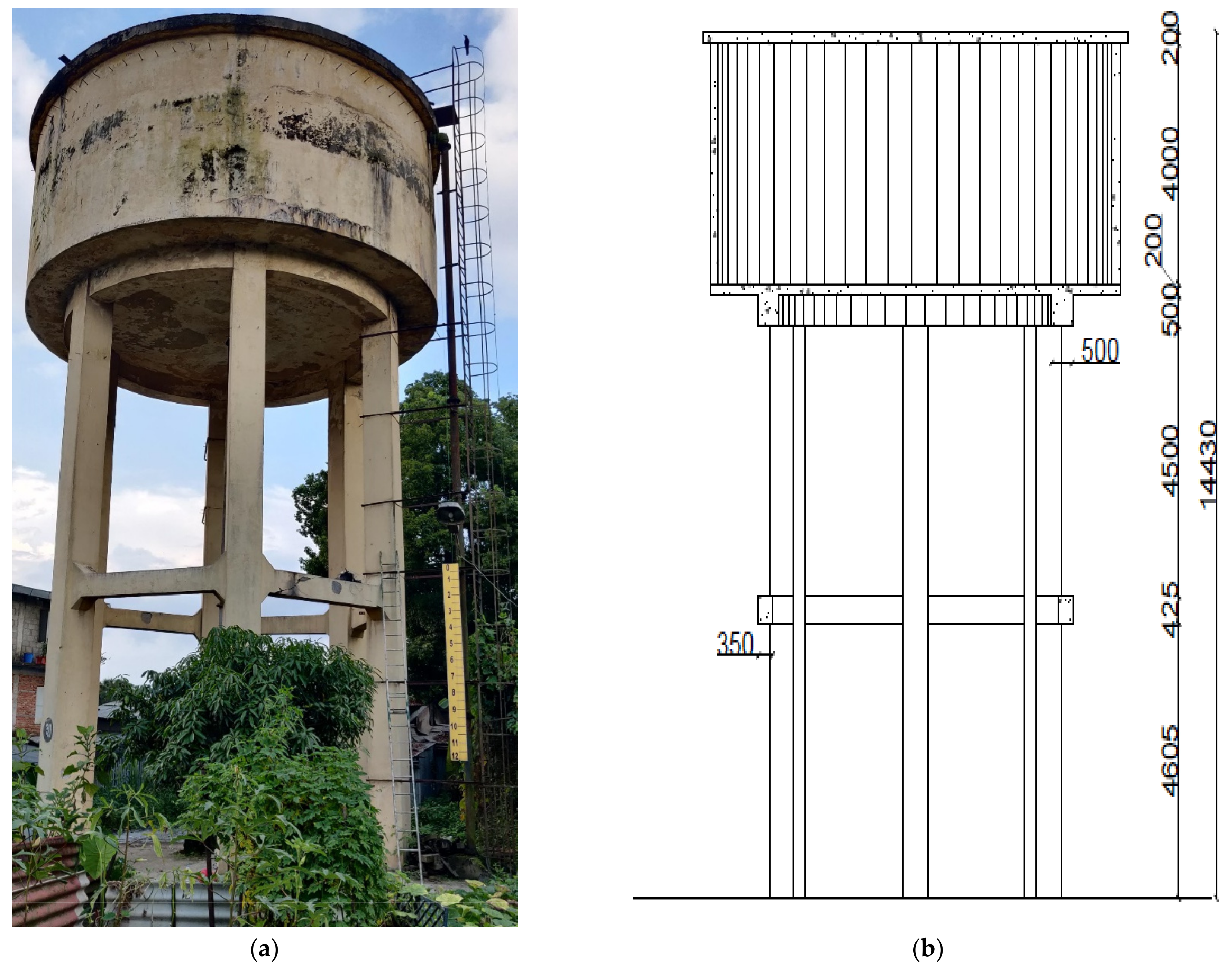
An existing water tank, situated in the northwestern part of Kathmandu having a cylindrical container and supported on RC frame staging, is used as a representative model. The tank was constructed in 1972. The tank is built on soft alluvial deposits of Kathmandu. The case study tank and its geometry are shown in Figure 1 and Figure 2. Some important properties of the tank is presented in Table 1. Material properties used in numerical modelling are listed in Table 2. Schmidt hammer testing and rebar scanning techniques were used to evaluate some material properties of the existing structure. The effects of aging and detailing uncertainties were addressed using in-situ measurements.
2.2. Finite Element Modeling
A finite element model of the tank was prepared in SAP 2000 v. 17 [18] for two scenarios. The first analysis scheme is for a fixed base model of the case study tank considering full, half, and empty reservoir conditions. The second analysis scheme considers soil flexibility consistent to the site condition. Columns and beams in the support system were modeled as frame elements, having two nodes with six degrees of freedom (three translations and three rotations) at each node. The ring beam at the top was modeled as thick shell element having four nodes, each having six degrees of freedom (three translations and three rotations). Bottom slab, side walls and top slabs were modeled as thin shell elements having four nodes, each having six degrees of freedom (three translations and three rotations). The staging beams and columns were assigned with plastic hinges to model inelastic behavior. Beam elements were assigned with auto M3 flexural hinges and column elements were assigned with auto P-M2-M3 hinge at each node. Fluid structure interaction is considered in half and full reservoir conditions. A three-dimensional finite element model is presented in Figure 3. Pushover and nonlinear time history analyses were conducted to estimate capacity and displacement demands of the structure, respectively. Using the pushover curve, four damage states: slight, moderate, extensive, and collapse were defined per the yield and ultimate displacements following the method proposed by [19]. The center of gravity of the top slab is taken as the point of interest at which displacement is measured. For time history analysis, seven ground motions with peak ground acceleration (PGA) ranging from 0.15g to 0.75g were used. The ground acceleration time histories used in this study along with their moment magnitudes and recording stations are summarized in Table 3.
The demand parameter is taken as the peak absolute displacement of the center of gravity of the top slab. Demand to capacity ratio (DCRLS) is then determined for each damage state. The ground motions should be selected in such a way that the criteria of DCR greater than unity is fulfilled for any selected ground motion. Ground motion intensity parameter is selected as the spectral acceleration corresponding to the first vibration mode of the structural model, denoted here as Sa (T1, ζ). Analytical fragility curves were obtained using the cloud analysis approach proposed by [20].
2.3. Fluid Structure Interaction
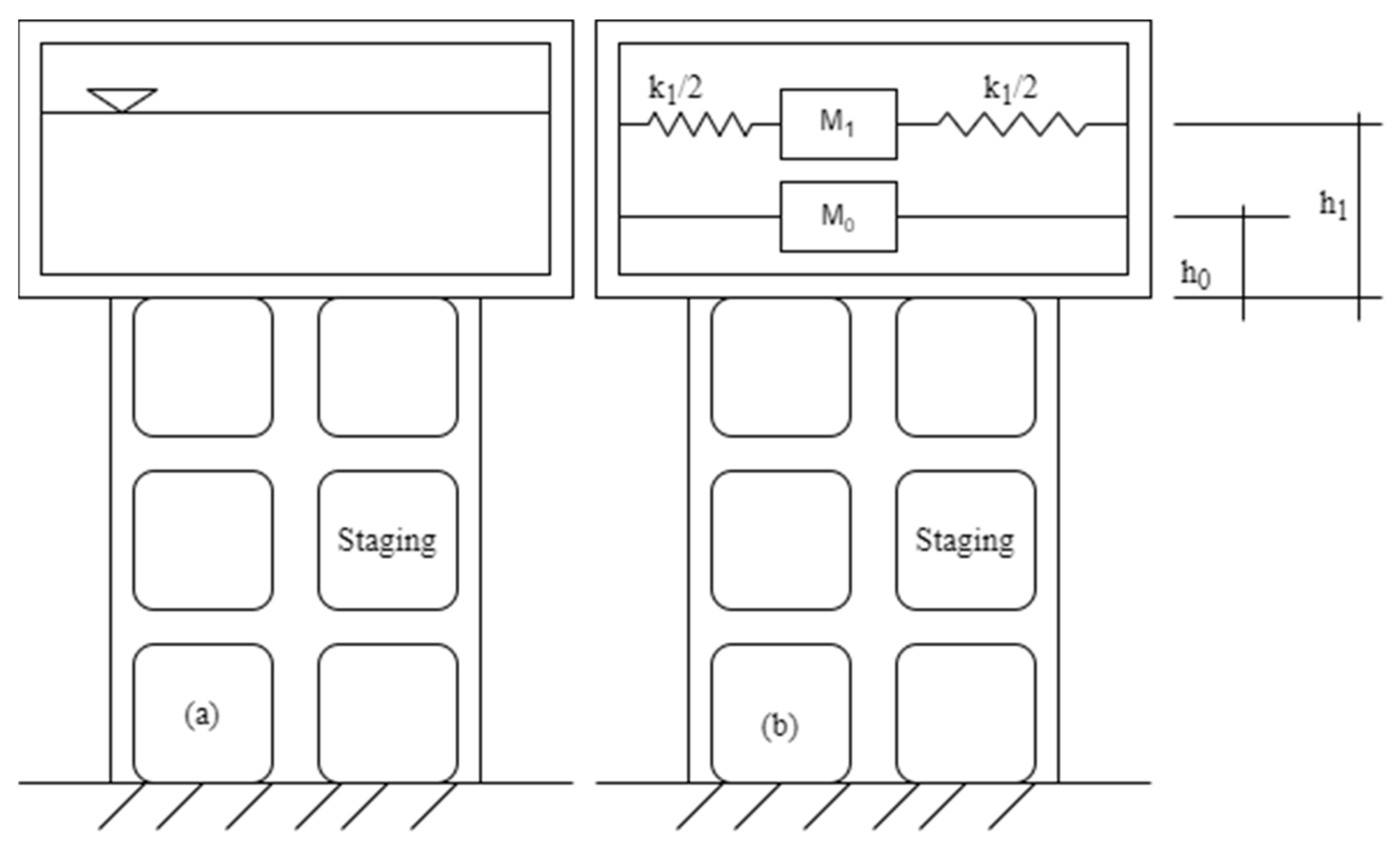
The vibration of liquid induces impulsive and convective hydrodynamic pressures together with hydrostatic pressure on the wall and base of the tank except in the case of empty condition. To incorporate the effect of fluid–structure interaction, equivalent idealization suggested by Housner [3] is adopted. This approach makes use of a spring mass model (Figure 4). The impulsive mass of liquid in the tank, M0 is rigidly attached to tank wall at height h0. Similarly, the convective mass, M1 is attached to the tank wall at h1 by a spring of stiffness k1, as shown in Figure 4. Housner [3] suggested the use of the first convective mass since the design of elevated tanks incorporates the convective mass leaving behind the higher modes of sloshing due to their marginal contribution to container wall force [6].
Spring and joint mass were used to incorporate fluid-structure interaction in the finite element model. All the parameters of the spring mass model, including convective mass, impulsive mass, spring constant, and height of application of convective and impulsive mass were calculated as per the IITK-GSDMA guidelines [21]. The impulsive mass is attached to the node of shell element (wall) at a height h0 in the u1 direction and distributed equal number of nodes (n). At the level of h1, n radial links each with spring constant (K1/n) were assigned in the u1 direction. Then, the convective mass (M1/n) was applied at the center of the radial link in the u1 direction, as shown in Figure 5.
2.4. Soil Flexibility
The flexibility of underlying soil can affect dynamic response of structures. A previous study by [22] demonstrated the importance of soil–structure interaction in a building constructed in the Kathmandu Valley. Foundation flexibility at the tank site is considered in this study by using spring elements. The structure under consideration consists of a mat foundation with 1.84 m depth below the ground level. The footing is a circular raft 10.2 m in diameter and 0.34 m thick. The raft is stiffened by beams of size 0.55 × 0.535 m. In the fixed-base model, all the six degrees of freedom of the node at the base of the columns is fully fixed. For the flexible soil model, link elements are assigned to the node at the base of the columns. The properties of the link elements are based on the equations given in [23]. Gazetas [23] developed expressions to estimate dynamic stiffnesses (K) and damping coefficients (C) for harmonically excited homogeneous half-space. The footing was idealized as a circular plate resting on a semi-infinite homogeneous elastic half-space. Then, the dynamic stiffness and damping coefficients can be determined using equations proposed by [23]. The shear modulus, G, can be estimated using G = ρVs2, with ρ and vs. representing, respectively the mass density and shear wave velocity of soil. The dynamic stiffness can be determined by multiplying dynamic stiffness factor with static stiffness. This factor is frequency-dependent and is given as a function of a non-dimensional parameter, a0, where a0 = ωB/Vs; ω being the angular frequency of the forcing harmonic excitation, and B is the radius of the footing. Frequency-dependence of the stiffness and damping coefficients is not considered. The average shear wave velocity for the site was estimated using the equation proposed by [24], with relevant properties of the foundation and soil listed in Table 4.
The spring constants and radiation dashpot coefficients for the foundation were estimated by considering a circumscribed rectangle as suggested by [23]. Since all the columns are erected on a mat and are symmetrical to both axes, the calculated values were distributed equally in each support.
2.5. Construction of Fragility Function
The probability of reaching or surpassing a particular damage state or performance level for the specific value of the intensity measure is expressed in terms of fragility function. Four different approaches, namely analytical empirical, heuristic, and hybrid, are in practice to construct fragility functions [25]. Various types of fragility functions and the construction processes are reported elsewhere (see, for example, [26,27,28,29,30,31,32]). We adopted the method proposed by [20]. The method relies on regression between DCRLS (damage to capacity ratio for a particular performance/damage level) and ground motion intensity parameter. The regression model is represented by
where is the damage to capacity ratio for a limit state LS and ground motion i, N is the number of ground motions used, is the median for a given , is the median corresponding to of ground motion i; and a and b are regression parameters. The fragility is then expressed as:
where is the standard Gaussian cumulative distribution function.
Fragility functions for four damage states, as postulated by [19], were created for empty, half, and full reservoir conditions. The damage states were defined from the pushover curve using the approach suggested by [25]. The four damage states based on yield (dy) and ultimate displacements (du) are described in Table 5.
3. Results and Discussions
We first derived fragility functions for four damage states under three reservoir conditions: full, half, and empty, considering fixed base analysis. Thereafter, we incorporated the effect of soil flexibility. Seismic fragility functions for full reservoir condition are shown in Figure 6. As shown in Figure 6, the effect of soil structure interaction for full reservoir condition is significant at higher damage states. When the tank is full, exceedance probabilities of slight, moderate, extensive, and collapse damage states are 99.70%, 89.76%, 59.96%, and 26.11%, respectively, at 0.6g when soil flexibility is not considered. The corresponding exceedance probabilities with soil flexibility are 99.83%, 91.58%, 68.36%, and 33.15%. This clearly shows that fixed-based models result in lower fragility estimates at higher damage states.
Seismic fragility functions for the half reservoir condition are presented in Figure 7. The effect of soil–structure interaction is more pronounced at higher damage states. For instance, the exceedance probabilities of slight, moderate, extensive, and collapse damage states without considering soil flexibility are 98.42%, 77.81%, 38.83%, and 12.29%, respectively, at 0.6 g. The corresponding probabilities with soil flexibility are 98.88%, 79.21%, 50.22%, and 19.83%, respectively. A comparison of Figure 6 and Figure 7 shows that the fully filled water tank is more fragile than the half-filled tank.
Seismic fragility functions for the empty tank are presented in Figure 8. As in the previous two cases, fragility of tanks built on soft soils are higher than those at rigid ground, especially at higher damage states. For example, exceedance probabilities for slight, moderate, extensive, and collapse damage states are 94.32%, 61.39%, 21.11%, and 5.00%, respectively, at 0.6g when soil flexibility is not considered. The corresponding probabilities for soft soil conditions are 94.71%, 63.41%, 33.34%, and 11.62%. The rate at which the fragilities of fixed base and flexible base models diverge from each other with increasing ground motion intensity is the highest in the empty tank condition. A comparison of Figure 6, Figure 7 and Figure 8, shows that the amount of water present in the tank has significant impact on seismic fragility, and the impact is higher at higher damage states. While some studies such as [33] found that soil flexibility does not significantly impact the seismic fragility of low-rise RC buildings in Kathmandu Valley, our results highlight, for similar soil conditions, its importance in special structures, such as elevated water tanks. For similar overall height, structures such as overhead water tanks are more flexible than typical RC buildings such as the one used in [33]. A limitation of the presented study is simplification in the modelling of fluid– and soil–structure interactions. Sloshing induced hydrodynamic damping and frequency-dependence of soil springs are not accounted for in this study. This might lead to some uncertainties in the overall fragility curves presented here, but the main conclusions regarding the effect of soil flexibility are expected to hold.
4. Conclusions
Water supply systems play an instrumental role in the aftermath of an earthquake in terms of clean drinking water and firefighting. Thus, the seismic performance of elevated water tanks is crucial to evaluate beforehand. More importantly, elevated water tanks with smooth bars that were constructed several decades ago are further challenging due to the uncertainties in their material behavior. This study is an attempt to assess the seismic vulnerability of aging elevated water tanks with smooth bars considering fluid–structure and soil–structure interactions. We considered three reservoir conditions: full, half, and empty and analyzed an existing water tank with field identified material properties. Fragility functions for three reservoir conditions with and without consideration of soil flexibility are derived. The full reservoir condition is found to be more vulnerable than half and empty reservoir conditions. When fluid–structure interaction is kept constant, we conclude that the soil structure interaction effect is very prominent, especially at higher damage states. For example, exceedance probabilities for extensive damage state for full reservoir condition are obtained as 89% and 82% for with and without soil structure interaction at 1g, respectively. For collapse damage state, exceedance probabilities are respectively obtained as 62% and 52% for with and without soil structure interaction scenarios under full reservoir condition. In the case of half reservoir condition, exceedance probabilities for extensive damage state are obtained as 73% and 65%, respectively, for with and without soil structure interaction. The collapse damage state for the same condition depicts 42% and 32% exceedance probabilities at 1 g for with and without soil structure interaction. Similarly, at 1 g, the empty reservoir condition depicts exceedance probabilities of extensive damage state as 58% and 42%, respectively, for with and without soil structure interaction scenario. In the case of collapse damage state, the same tank depicts exceedance probabilities of 28% and 15%, respectively, for with and without soil structure interaction at 1 g. The rate at which the fragility of a flexible base structure diverges from that of a fixed base one with increasing ground motion intensity is found to be the largest when the tank is empty. Future studies could consider the effect of stiffness degradation to create more realistic models for aging water tanks. Future research may consider the dynamic identification of modal parameters and model updating for tanks with uncertainties so as to create a refined finite element model or achieve finite element model updating. Hydrodynamic models of sloshing water and dynamic stiffening and damping of the underlying soil model could also be improved.
Author Contributions
Conceptualization, D.G.; methodology, D.G. and R.R.; software, H.R. and D.G.; validation, R.R.; formal analysis, H.R. and D.G.; investigation, D.G.; resources, P.P.; data curation, H.R.; writing—original draft preparation, H.R. and D.G.; writing—review and editing, P.P. and R.R.; visualization, P.P.; supervision, D.G., P.P. and R.R. All authors have read and agreed to the published version of the manuscript.
Funding
This research received no external funding.
Institutional Review Board Statement
Not applicable.
Informed Consent Statement
Not applicable.
Acknowledgments
Authors are grateful to Adely Engineering Consult, Lalit Bhatt, Govind Raj Bhatt, Pushkar Koirala, and Naresh Subedi for their supports at various points of this research. Rajesh Rupakhety acknowledges support from the University of Iceland Research Fund.
Conflicts of Interest
The authors declare no conflict of interest.
References
- Gautam, D.; Rupakhety, R. Empirical seismic vulnerability analysis of infrastructure systems in Nepal. Bull. Earthq. Eng. 2021, 19, 6113–6127. [Google Scholar] [CrossRef]
- Gautam, D. Unearthed lessons of 25 April 2015 Gorkha earthquake (MW 7.8): Geotechnical earthquake engineering perspectives. Geomat. Nat. Hazards Risk 2017, 8, 1358–1382. [Google Scholar] [CrossRef] [Green Version]
- Housner, G.W. The dynamic behavior of water tanks. Bull. Seismol. Soc. Am. 1963, 53, 381–387. [Google Scholar] [CrossRef]
- Dutta, S.C.; Dutta, S.; Roy, R. Dynamic behavior of R/C elevated tanks with soil-structure interaction. Eng. Struct. 2009, 31, 2617–2629. [Google Scholar] [CrossRef]
- Sezen, H.; Livaoglu, R.; Dogangun, A. Dynamic analysis and seismic performance evaluation of above-ground liquid-containing tanks. Eng. Struct. 2008, 30, 794–803. [Google Scholar] [CrossRef]
- Livaoǧlu, R.; Doǧangün, A. Simplified seismic analysis procedures for elevated tanks considering fluid-structure-soil interaction. J. Fluids Struct. 2006, 22, 421–439. [Google Scholar] [CrossRef]
- Mori, C.; Sorace, S.; Terenzi, G. Seismic assessment and retrofit of two heritage-listed R/C elevated water storage tanks. Soil Dyn. Earthq. Eng. 2015, 77, 123–136. [Google Scholar] [CrossRef]
- Mansour, A.M.; Kassem, M.M.; Nazri, F.M. Seismic vulnerability assessment of elevated water tanks with variable staging pattern incorporating the fluid-structure interaction. Structures 2021, 34, 61–77. [Google Scholar] [CrossRef]
- Farajian, M.; Khodakarami, M.I.; Kontoni, D.P.N. Evaluation of soil-structure interaction on the seismic response of liquid storage tanks under earthquake ground motions. Computation 2017, 5, 17. [Google Scholar] [CrossRef] [Green Version]
- Moslemi, M.; Kianoush, M.R.; Pogorzelski, W. Seismic response of liquid-filled elevated tanks. Eng. Struct. 2011, 33, 2074–2084. [Google Scholar] [CrossRef]
- Haroun, M.A.; Temraz, M.K. Effects of soil-structure interaction on seismic response of elevated tanks. Soil Dyn. Earthq. Eng. 1992, 11, 73–86. [Google Scholar] [CrossRef]
- Kianoush, M.R.; Ghaemmaghami, A.R. The effect of earthquake frequency content on the seismic behavior of concrete rectangular liquid tanks using the finite element method incorporating soil-structure interaction. Eng. Struct. 2011, 33, 2186–2200. [Google Scholar] [CrossRef]
- Kirtas, E.; Rovithis, E.; Makra, K. On the modal response of an instrumented steel water-storage tank including soil-structure interaction. Soil Dyn. Earthq. Eng. 2020, 135, 106198. [Google Scholar] [CrossRef]
- Caprinozzi, S.; Dolšek, M. Seismic performance assessment of non-code-conforming and code-conforming supporting structures of elevated tanks using conventional and risk-based decision models. Eng. Struct. 2020, 227, 111469. [Google Scholar] [CrossRef]
- Dutta, S.C.; Jain, S.K.; Murty, C.V.R. Assessing the seismic torsional vulnerability of elevated tanks with RC frame-type staging. Soil Dyn. Earthq. Eng. 2000, 19, 183–197. [Google Scholar] [CrossRef]
- Dutta, S.; Mandal, A.; Dutta, S. Effect of earthquake characteristics on seismic performance of RC elevated water tanks considering fluid level within the vessels. Eng. Struct. 2011, 31, 97–113. [Google Scholar] [CrossRef]
- Terenzi, G.; Rossi, E. Seismic analysis and retrofit of the oldest R/C elevated water tank in Florence. Bull. Earthq. Eng. 2018, 16, 3081–3102. [Google Scholar] [CrossRef]
- Computers and Structures Inc. SAP2000 v. 20; CSI Inc.: Pomona, CA, USA, 2013. [Google Scholar]
- Lagomarsino, S.; Giovinazzi, S. Macroseismic and mechanical models for the vulnerability and damage assessment of current buildings. Bull. Earthq. Eng. 2006, 4, 415–443. [Google Scholar] [CrossRef]
- Jalayer, F.; Ebrahimian, H.; Miano, A.; Manfredi, G.; Sezen, H. Analytical fragility assessment using unscaled ground motion records. Earthq. Eng. Struct. Dyn. 2017, 46, 2639–2663. [Google Scholar] [CrossRef]
- Jain, S.K.; Jaiswal, O.R. IITK-GSDMA Guidelines for Seismic Design of Liquid Storage Tanks; Gujarat State Disaster Management Authority: Gujrat, India, 2007. [Google Scholar]
- Dhakal, R.; Rupakhety, R.; Gautam, D. System identification and seismic performance assessment of representative RC buildings in Kathmandu Valley. Front. Built Environ. 2020, 6, 601116. [Google Scholar] [CrossRef]
- Gazetas, G. Formulas and charts for impedances of surface and embedded foundations. J. Geotech. Eng. 1991, 117, 1363–1381. [Google Scholar] [CrossRef]
- Gautam, D. Empirical correlation between uncorrected standard penetration resistance (N) and shear wave velocity (VS) for Kathmandu Valley, Nepal. Geomat. Nat. Hazards Risk 2017, 8, 496–508. [Google Scholar] [CrossRef]
- Elnashai, A.S.; di Sarno, L. Fundamentals of Earthquake Engineering: From Source to Fragility; John Wiley & Sons: New York, NY, USA, 2008; Volume 43. [Google Scholar]
- Bessason, B.; Bjarnason, J.Ö.; Rupakhety, R. Statistical modelling of seismic vulnerability of RC, timber and masonry buildings from complete empirical loss data. Eng. Struct. 2020, 209, 109969. [Google Scholar] [CrossRef]
- Shinozuka, M.; Feng, M.Q.; Lee, J.; Naganuma, T. Statistical analysis of fragility curves. J. Eng. Mech. 2002, 126, 1224–1231. [Google Scholar] [CrossRef] [Green Version]
- Porter, K.; Kennedy, R.; Bachman, R. Creating fragility functions for performance-based earthquake engineering. Earthq. Spectra 2007, 23, 471–489. [Google Scholar] [CrossRef] [Green Version]
- Gautam, D.; Fabbrocino, G.; de Magistris, F.S. Derive empirical fragility functions for Nepali residential buildings. Eng. Struct. 2018, 171, 617–628. [Google Scholar] [CrossRef]
- Gautam, D.; Adhikari, R.; Rupakhety, R. Seismic fragility of structural and non-structural elements of Nepali RC buildings. Eng. Struct. 2021, 232, 111879. [Google Scholar] [CrossRef]
- Rota, M.; Penna, A.; Strobbia, C.L. Processing Italian damage data to derive typological fragility curves. Soil Dyn. Earthq. Eng. 2008, 28, 933–947. [Google Scholar] [CrossRef]
- Moschonas, I.F.; Kappos, A.J.; Panetsos, P.; Papadopoulos, V.; Makarios, T.; Thanopoulos, P. Seismic fragility curves for greek bridges: Methodology and case studies. Bull. Earthq. Eng. 2009, 7, 439–468. [Google Scholar] [CrossRef]
- Adhikari, R.; Rupakhety, R.; Giri, P.; Baruwal, R.; Subedi, R.; Gautam, R.; Gautam, D. Seismic fragility analysis of low-rise RC buildings with brick infills in high seismic region with alluvial deposits. Buildings 2022, 12, 72. [Google Scholar] [CrossRef]
Figure 1.
Case study tank: (a) existing, (b) geometry of the tank (all dimensions are in mm).

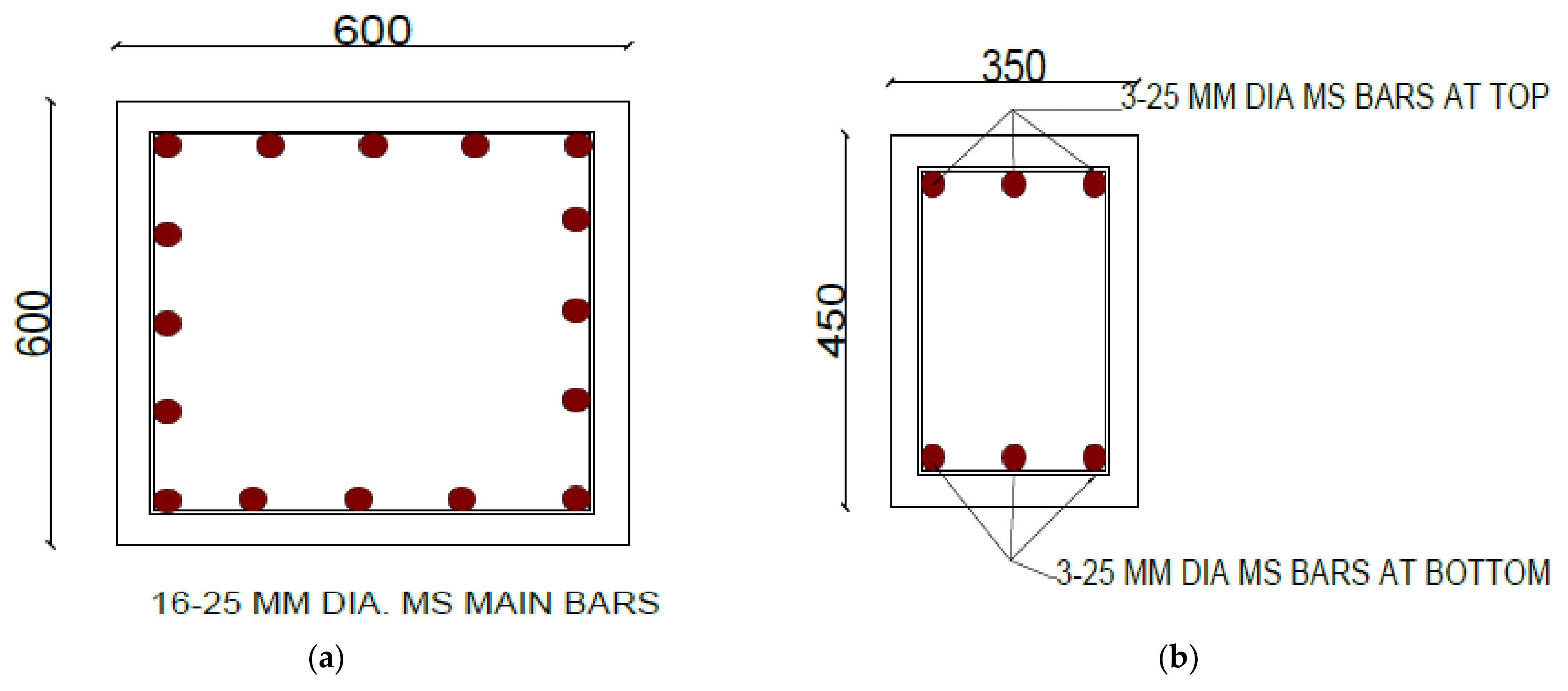
Figure 2.
Structural details of (a) column (b) beam.

Figure 3.
A 3D finite element model of the case study tank.

Figure 4.
Spring mass model for fluid-structure interaction.

Figure 5.
Spring mass model, convective mass attached to tank wall through link and impulsive mass rigidly attached to the tank wall.
Figure 5.
Spring mass model, convective mass attached to tank wall through link and impulsive mass rigidly attached to the tank wall.

Figure 6.
Fragility functions for RC elevated water tanks with smooth bars with and without considering soil structure interaction for full reservoir condition.
Figure 6.
Fragility functions for RC elevated water tanks with smooth bars with and without considering soil structure interaction for full reservoir condition.

Figure 7.
Fragility functions for RC elevated water tanks with smooth bars with and without considering soil structure interaction for half reservoir condition.
Figure 7.
Fragility functions for RC elevated water tanks with smooth bars with and without considering soil structure interaction for half reservoir condition.

Figure 8.
Fragility functions for RC elevated water tanks with smooth bars with and without considering soil structure interaction for empty reservoir condition.
Figure 8.
Fragility functions for RC elevated water tanks with smooth bars with and without considering soil structure interaction for empty reservoir condition.


Table 1.
Geometrical properties of water tank.
| Parameter | Quantity |
|---|---|
| Tank capacity | 250 m3 |
| Height of staging | 9.53 m |
| Plinth height (from ground level) | 0.3 m |
| Footing depth (from ground level) | 2 m |
| C/C spacing of columns | 3.82 m |
| No. of staging | 1 |
| Column size | 609 mm |
| Footing pad size (rectangular) | 2 m |
| Intermediate beam width | 300 mm |
| Intermediate beam depth | 425 mm |
| Top beam width | 500 mm |
| Top beam depth | 700 mm |
Table 2.
Materials properties of case study tank.
| Concrete | Reinforcement Bars | ||
|---|---|---|---|
| E (MPa) | 22,360.68 | E (MPa) | 2 × 10⁵ |
| fck (MPa) | 20 | fy (MPa) | 250 |
| Unit Weight (KN/m3) | 25 | Unit weight (KN/m3) | 76.973 |
Table 3.
Ground acceleration time histories used for nonlinear time history analysis.
| Earthquake | Magnitude (Mw) | PGA (g) | Recording Station |
|---|---|---|---|
| Gorkha (2015) | 7.8 | 0.1771 | Kathmandu |
| Imperial Valley-06 (1979) | 6.53 | 0.2354 | EC County Center FF |
| Kocaeli (1999) | 7.51 | 0.3642 | Duzce |
| Northridge-01 (1994) | 6.69 | 0.4434 | Beverly Hills-14145 |
| Loma Prieta (1989) | 6.93 | 0.5699 | LGPC |
| Kobe Japan (1995) | 6.9 | 0.6711 | Takatori |
| Chi-Chi Taiwan (1999) | 7.62 | 0.7604 | CHY028 |
Table 4.
Summary of parameters for modelling soil flexibility.
| Shape of Foundation | Circular Mat Foundation |
|---|---|
| Diameter of mat | 10.2 m |
| Uncorrected N-value | 5 |
| Shear wave velocity (Vs30) | 138.68 m/s |
| Poisson’s ratio (ט) | 0.4 |
| Mass density of foundation soil (ƍ) | 1.65 Mg/m3 |
| Modulus of rigidity of soil (G) | 31,733.03 KN/m2 |
Table 5.
Structural damage states considered for fragility analysis (after [19]).
Table 5.
Structural damage states considered for fragility analysis (after [19]).
| Capacity Function | Limit State | Qualitative Description |
|---|---|---|
| SDS1: 0.7dy | Slight Damage (DS1) | No structural damage, slight non-structural damage |
| SDS2: 1.5dy | Moderate Damage (DS2) | Slight structural damage, moderate non-structural damage |
| SDS3: 0.5(dy + du) | Extensive Damage (DS3) | Moderate structural damage, heavy non-structural damage |
| SDS4: du | Complete Damage (DS4) | Heavy to very heavy structural and non-structural damage |
Disclaimer/Publisher’s Note: The statements, opinions and data contained in all publications are solely those of the individual author(s) and contributor(s) and not of MDPI and/or the editor(s). MDPI and/or the editor(s) disclaim responsibility for any injury to people or property resulting from any ideas, methods, instructions or products referred to in the content. |
© 2022 by the authors. Licensee MDPI, Basel, Switzerland. This article is an open access article distributed under the terms and conditions of the Creative Commons Attribution (CC BY) license (https://creativecommons.org/licenses/by/4.0/).
Share and Cite
MDPI and ACS Style
Rimal, H.; Pradhan, P.; Gautam, D.; Rupakhety, R. Seismic Fragility of Aging Elevated Water Tank with Smooth Bars Considering Soil Structure Interaction. Buildings 2023, 13, 4. https://0-doi-org.brum.beds.ac.uk/10.3390/buildings13010004
AMA Style
Rimal H, Pradhan P, Gautam D, Rupakhety R. Seismic Fragility of Aging Elevated Water Tank with Smooth Bars Considering Soil Structure Interaction. Buildings. 2023; 13(1):4. https://0-doi-org.brum.beds.ac.uk/10.3390/buildings13010004
Chicago/Turabian StyleRimal, Hariram, Piyush Pradhan, Dipendra Gautam, and Rajesh Rupakhety. 2023. "Seismic Fragility of Aging Elevated Water Tank with Smooth Bars Considering Soil Structure Interaction" Buildings 13, no. 1: 4. https://0-doi-org.brum.beds.ac.uk/10.3390/buildings13010004
Note that from the first issue of 2016, this journal uses article numbers instead of page numbers. See further details here.