Article

Comparative Response Spectrum Analysis on 15- and 50-Story Reinforced Concrete Buildings Having Shear Walls with and without Openings as per EN1998-1 Seismic Code

by
Mistreselasie Abate
1,
Ana Catarina Jorge Evangelista
1,* and
Vivian W. Y. Tam
2
1
School of Engineering, Civil Engineering, Engineering Institute of Technology, Perth, WA 6005, Australia
2
School of Engineering, Design and Built Environment, Western Sydney University, Penrith, NSW 2751, Australia
*
Author to whom correspondence should be addressed.
Submission received: 6 April 2023 / Revised: 10 May 2023 / Accepted: 11 May 2023 / Published: 16 May 2023

Abstract

:
Medium-rise reinforced concrete (RC) framed apartment complexes with stories ranging from 15 to 50 are becoming more common in Ethiopia’s main cities. In these RC-framed structures, shear walls are included for lateral load resistance. As apertures are frequently provided in shear walls, it is critical to evaluate their influence on story drift, stiffness, shear and moments, and stress within the shear walls. A 3D study with five different cases was carried out with ETABS version 19.00 software to investigate the influence of apertures in a building’s shear wall. This study looks at the effects of changing the size and location of these apertures. Based on this analysis, extensive data were acquired, and useful conclusions were formed that will be useful to practicing engineers. The seismic parameter utilized for the response spectrum study was Building Code of Ethiopia ES8-15, which conforms to Eurocode 8-2004 seismic code guidelines (based on EN1998-1) with target response spectrum type-I. The following parameters were used: ground acceleration, ag/g = 0.1, spectrum type = I, ground type = B, soil factor, S = 1.35, spectrum period, Tb, = 0.05 s, spectrum period, Tc = 0.25 s, spectrum period, Td = 1.2 s, lower bound factor, beta = 0.2, behavior factor = 1, and damping ratio = 5%. The outcomes are compared using various parameters such as displacement, story drift, story stiffness, story shear, and story moment both with and without shear wall opening cases. This study will give tremendous insight into the effect of shear wall openings on the performance of the structure. The analysis in this work was carried out on a linear model, which may not represent the complete local response of the structure; thus, future researchers should perform nonlinear analysis based on a performance-based design. It was concluded from this investigation that incorporating shear walls considerably enhanced the performance of the building over framed structures. Shear wall openings in a structure have a significant influence on the building’s performance. Due to their significant resistance to earthquake forces, shear wall structures are highly recommended for seismic hazard zones.

1. Introduction

Reinforced concrete (RC) structures can face significant horizontal and vertical loads. The most standard designs for which shear partitions are designed are for wind and seismic events [1]. Shear walls offer the necessary power in opposition to seismic pressures and are the highest quality and most effective technique to absorb those lateral stresses [2,3,4]. Seismic walls are container factors that help the structure from the perimeters. Shear partitions provide lateral power and stiffness [5,6,7,8]. Since shear walls are liable to experience extensive lateral stresses, the tilting impact is crucial, which has to be taken into consideration within the design of the structure. To avoid negative outcomes of torsion, shear partitions in systems must be symmetrical [9,10,11].
Shear walls may be placed symmetrically in one or both directions. Earthquake-resistant walls are more powerful when they are constructed completely across the building. As a result, this configuration will increase the torsion resistance of the shape [12]. The behavior of a shear wall is decided by the materials used, the length of the wall, the thickness of the wall, the placement of the wall, and the construction. Due to their stiffness, load-bearing potential, and excessive ductility, RC shear partitions are used for the creation of high-rise structures in seismic zones [13,14,15]. Shear wall openings which are oriented alongside in-plane loading are more important than shear wall openings which can be located along out-of-surface loading. This is because a big shift in displacement is experienced whilst the shear wall opens. Loads within the plane are located together [16].
Due to their capacity to resist lateral stresses, which include earthquakes and wind loads, shear partitions are considered a critical factor within the construction industry. As a result, experiments have been performed to better apprehend the structural conduct of shear partitions under distinctive loading situations and instances. The seismic conduct of prefabricated strengthened shear partitions with vertical joints was investigated by Zhang and Wang [17,18], in which shear walls were constructed in a pilot building. Coccia et al. [19] studied the overall seismic performance of masonry partitions modified with vertical FRP stiffeners and found that conventional methods of seismic strengthening of masonry partitions have an impact on the seismic performance of the components. Generally, out-of-surface bending behavior is used for modification. Furthermore, Jeon et al. [20] investigated the seismic vulnerability of plain bolstered concrete shear partitions with tie beams and tested them in plain bolstered concrete shear partitions for high upward thrust buildings built with seven sets of ground movement factors and shear amplification elements of 1.2 and have been shown to be enough to fulfill FEMA P695 standards for the probability of disintegrating and restricting the ratio of collapse. Reinforced concrete structures with L-shaped partitions provide architects with numerous opportunities to design buildings with extra open space and variety [21,22,23]. As a way to promote compliance with the protection criteria imposed by numerous requirements, numerous experimental and numerical studies ought to be completed on L-shaped shear walls. Similarly, when deformability and power are required, L-shaped concrete disc partitions have a high ability to soak up lateral pressure and, if designed well, can absorb a substantial amount of seismic energy [24,25,26,27]. Network or retrofit issues, in addition to the proximity of elevators, home windows, doors, and stairways, may require shear wall openings [28]. Holes in a shear wall not only lessen the pressure around the hollow but additionally lessen the general structural ability and integrity of the wall [27].
The primary goal of this research is to recognize the conduct of stepped and normal openings and to analyze the effect of stepped openings on seismic loading with different masses. Shear walls without holes outperform shear partitions with vertical and staggered holes. Marius [29] determined the same results. On average, no matter where the shear wall starts, the presence of a shear wall in a constructing will greatly increase the seismic reaction of the building. Recently, a few researchers have carried out work comparable to this on the usage of finite element modeling to resolve structural and cloth problems, as seen in literature reports [30,31,32,33,34,35,36,37].
Shear walls or similar are included in a few excessive upward thrust houses and there may be a need to govern lateral deflection within flooring. Shear walls are prepared with openings that meet practical requirements. In some instances, wall openings for domestic home windows, doorways, and particular kinds of openings are unavoidable in shear walls. Shear partitions are vertical reinforced concrete beams that are usually very deep and skinny. They are regularly applied in systems to face gravity loads and floor shear. A shear wall is the vertical detail of a lateral strain suppression device that transfers lateral forces from the pinnacle diaphragm to the lower diaphragm or basis. A shear wall may be a load-bearing wall in a gravity load machine or part of a duplex gadget that is built to withstand lateral stresses [38].
Further, others have furnished seismic observations and evaluated the impact of shear partitions on multi-span RC frames. The seismic evaluation shows that RC frame geometry with shear partitions has high seismic resistance [39]. We evaluated rectangular, C, L, and T regular shear partitions. An average design for a 20-story RC structure was implemented [39].
A 10-story RC shear wall with and without openings placed under seismic loading was used with time information and pushover after modification for study. The study confirmed that a form with various levels of openness determined a large displacement of upward thrust with an opening period [40].
The development of a ten-story RC shear wall may be initiated under seismic loading, and the time records and stressors were changed for investigation. This study showed that constructs with distinctive layer openings show a large displacement increase in opening length [40]. Using the ability spectrum method, the shape of the plastic hinge remained consistent over time because the selection curve crossed the capability curve at in situ occupancy. The effects show that the arena-type shear wall modality has much less affiliation—primarily based on absolute shear. Layout—primarily based on displacement and shear—will grow in terms of open tops and bottoms [41]. Moreover, every test studied slightly upwardly pushed buildings with various designs and shear wall placements and determined that the construction’s center of mass and center of rigidity are closer to shear partitions than other walls. The shape of the shear wall and its surroundings influence the effect [42]. Some research has included multi-story shear wall installation shear partitions to reduce transverse and longitudinal pinnacle deflection [43]. Similarly, shear apertures have an impact on a construction’s seismic reaction. STAAD was used to simulate apertures and shear wall locations were investigated. A static identical assessment was used. The first-class displacement of homes with great-bridge apertures grew to 14% [44]. In the X and Y recommendations, buildings with staggered openings showed higher displacement, story float, and story shear outcomes than odd structures with staggered openings [45]. The overall performance of several shapes of shear walls has been evaluated using response spectrum assessment by Gupta [46] and it was observed that the common I-shaped shear wall has better results than all other shapes of shear wall. Columns were used to illustrate the shape, while the chosen version lacks a shear wall. In each unbiased model, the whole in-evaluation shear wall forms were studied. Story drifts, displacements, and shears are examples of analytical results. Rectangular and L-shaped partitions are more resistant to earthquakes than H- and T-shaped barriers [47]. The stiffness of squat RC robust shear walls was compared to standard reinforcement, in-built RC stiffness, and metallic tube stiffness. Shear partitions with RC stiffness and metal tube stiffness bear greater loads than normal reinforced shear partitions. Shear walls with reinforced concrete and steel tube stiffness have 34% and 9% better deformation ability than conventionally reinforced shear walls, respectively.
In comparison to historical strengthened shear partitions, metal tube stiffness, like RC stiffness, increased strain by 209% [48]. The association of shear walls turns out to be considerably changed to provide multi-story building shape [49]. The ETABS software program was used to explore the effect of constructing a shear wall at certain locations and configurations in projects and compared to those that do not include a shear wall [49]. Perimeter shear partitions exhibit 5.85% and 1.5% higher displacement than canter shear partitions in square and rectangular buildings, respectively [49]. A nook shear wall reduces the model’s length in every test, regardless of its expanded mass (s). Corner shear partitions have the least displacement (108.508 mm) due to stiffening, whereas standard frames have the most (303.339 mm) [50]. Outdoor shear partitions have proven to have the highest critical base share in each square and rectangular form. In comparison to rectangle-form homes, the strain in square-form homes with center partitions was 3.23% higher [51]. Although its mass grows, this version’s spectrum period (s) is reduced in a nook shear wall due to extended stiffness. The displacement is the least (108.508 mm) in the case of a corner shear wall and the biggest (303.339 mm) in the case of a conventional frame due to the stiffening of the form [52].
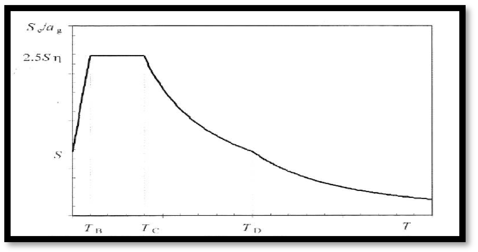
Therefore, the main objective of this study is to investigate the tremendous impact of shear wall openings on the overall performance of a structure during seismic loading as per a type-I response spectrum based on EN1998-1 [53].

2. Materials and Method

Project Description

For this study, a regular reinforced concrete building of 15 and 50 stories are considered in different 5 cases as shown in Figure 1, Figure 2, Figure 3, Figure 4, Figure 5 and Figure 6. The floor area of the 15-story structure is 900 sqm (30 m × 30 m) with 5 bays along each side (each span 6 m). The floor area of the 50-story structure is 225 sqm (15 m × 15 m) with 5 bays along each side (each span 3 m). The structure is modeled with 5 different cases of 50-story structures with each story height being 3 m and with and without a shear wall opening as shown in Figure 1, Figure 2, Figure 3, Figure 4, Figure 5 and Figure 6. Table 1, Table 2 and Table 3 shows the loading and building details of the sample model buildings.

3. Results

3.1. Sample 15-Story RC Building Results

Global Responses of 15-Story Building with and without Shear Wall Opening Results

After performing dynamic analysis for both structures with the case-1 and case-2 shear wall opening type, the obtained results were compared based on five factors, i.e., displacement, story drift, base shear, story shear, and story moment.
  • CM Displacement for Diaphragm D1
Table 4, Figure A3a and Figure A7a show the CM displacement for diaphragm D1 for a 15-story structure with and without shear wall opening response spectrum analysis outputs. From the results, it can be observed that the CM displacement for diaphragm D1 obtained by the shear wall with an opening is higher than that obtained by the shear wall without an opening for all stories. Shear wall with opening analysis gives a maximum of 15% in the X-direction and 12.38% in the Y-direction as higher results at the location of story 4. It can also be noticed that the percentage difference in CM displacement for diaphragm D1 calculated with and without shear wall openings decreases with the increase in height of the structure in both directions. This gives an excellent indication that for high-rise buildings the effect of openings might not be that much compared to low- and mid-rise buildings.
  • Drifts for Diaphragm D1
Table 5 and Figure A3b and Figure A7b show the drifts for diaphragm D1 for a 15-story structure with and without shear wall opening response spectrum dynamic analysis global responses. From the results, it can be observed that the drifts for diaphragm D1 obtained by a shear wall with an opening are higher than those obtained by a shear wall without an opening for all stories. A shear wall with opening analysis gives 27.39% in the X-direction and 17.23% in the Y-direction direction as higher results. It can also be noticed that the difference in drifts for diaphragm D1 calculated with and without a shear wall opening decreases with the increase in height of the structure in both directions. This gives an excellent indication that for high-rise buildings the effect of openings might not be that much compared to low- and mid-rise buildings.
  • Max Story Displacement
Table 6 and Figure A4a and Figure A8a show the max story displacement for a 15-story structure with and without shear wall opening response spectrum analysis global responses. From the results it can be observed that the max story displacement obtained by a shear wall with an opening is higher than that obtained by a shear wall without an opening for all stories. Shear wall with opening analysis gives a maximum of 21.13% in the X-direction and 13.33% in the Y-direction as higher results in story 4. It can also be noticed that the percentage difference in max story displacement calculated with and without shear wall openings decreases with the increase in height of the structure in both directions. This gives an excellent indication that for high-rise buildings the effect of openings might not be that much compared to low- and mid-rise buildings.
  • Maximum Story Drift
Table 7 and Figure A4b and Figure A8b show the max story drifts for a 15-story structure with and without shear wall opening response spectrum dynamic analysis results. From the results, it can be observed that the max story drifts obtained by a shear wall with an opening are higher than that obtained by a shear wall without an opening for all stories. Shear wall with opening analysis gives 27.39% in the X-direction and 17.23% in the Y-direction as higher results. It can also be noticed that the difference in max story drifts calculated by percentage differences with and without a shear wall decreases with the increase in height of the structure in both directions. This gives an excellent indication that for high-rise buildings the effect of openings might not be that much compared to low- and mid-rise buildings.
  • Maximum Story Shear
Table 8 and Figure A5b and Figure A9b show the max story shear for a 15-story structure with and without shear wall opening response spectrum dynamic analysis. From the results, it can be observed that the max story shear obtained by a shear wall with an opening is lower than that obtained by a shear wall without an opening for all stories. Shear wall with opening analysis gives 15.03% in the X-direction and 12.7% in the Y-direction as lower results. It can also be noticed that the difference in max story shear calculated with and without a shear wall opening increases with the increase in height of the structure In both directions.
  • Maximum Overturning Moment
Table 9 and Figure A5a and Figure A9a show the overturning moment for a 15-story structure with and without a shear wall opening response spectrum dynamic analysis. From the results, it can be observed that the overturning moment obtained by a shear wall with an opening is lower than that obtained by a shear wall without an opening for all stories. Shear wall with opening analysis gives 10.64% in the X-direction and 14.71% in the Y-direction as lower results. It can also be noticed that the difference in overturning moment calculated with and without a shear wall opening decreases with the increase in height of the structure in both directions. This gives an excellent indication that for high-rise buildings the effect of openings might not be that much compared to low- and mid-rise buildings.
  • Story Stiffness
Table 10 and Figure A6 and Figure A10 show the story stiffness for 15-story structure with and without a shear wall opening response spectrum dynamic analysis. From the results, it can be observed that the story stiffness obtained by a shear wall with an opening is lower than that obtained by a shear wall without an opening for all stories. Shear wall with opening analysis gives 25.48% in the X-direction and 20.59% in the Y-direction as lower results at story 2. It can also be noticed that the difference in story stiffness calculated with and without a shear wall opening varies with the increase in height of the structure in both directions.

3.2. Sample 50-Story RC Building Results

Global Responses of 50-Story Building with and without Shear Wall Opening Results
  • CM Displacement for Diaphragm D1
Figure A11a, Figure A15a, Figure A19a, Figure A23a and Figure A27a show the CM displacement for diaphragm D1 for a 50-story structure with and without a shear wall opening and framed structure response spectrum dynamic analysis global responses. From the results it can be observed that the CM displacement for diaphragm D1 obtained by a shear wall with an opening is higher than that obtained by a shear wall without an opening for all stories. Shear wall with opening analysis of case-1 gives 5.45% in the X-direction and 4.83% in the Y-direction as higher results. Case-2 gives 9.33% in the X-direction and 8.19% in the Y-direction as higher results. Case-3 gives 20.36% in the X-direction and 18.03% in the Y-direction as higher results. Case-4 gives a surprising result that for a framed structure the CM displacement of the bottom part of the structure is extremely high compared with the case-5 building with a shear wall without an opening with 36.434% in the X-direction and 44.54% in the Y-direction as higher results. At the same time, case-4 gives a surprising result that for a framed structure the percentage difference for displacement for the upper part of the structure is extremely low compared with the case-5 building with a shear wall without an opening with 14.61% in the X-direction and 12.43% in the Y-direction as lower results at story 30. It can also be noticed that the difference in the percentage of CM displacement for diaphragm D1 calculated with and without a shear wall opening decreases with the increase in height of the structure in both directions. This gives an excellent indication that, for high-rise buildings, introducing shear walls and openings is not the final and only solution for seismic-prone areas. It is necessary to look for other advanced lateral force-resisting systems such as viscous damping and other relevant technologies.
  • Drifts for Diaphragm D1
Figure A11b, Figure A15b, Figure A19b, Figure A23b and Figure A27b show the drifts for diaphragm D1 for a 50-story structure with and without a shear wall opening and framed structure response spectrum dynamic analysis global responses. From the results it can be observed that the drifts for diaphragm D1 obtained by a shear wall with an opening are higher than those obtained by a shear wall without an opening for all stories. Shear wall with opening analysis of case-1 gives 7.44% in the X-direction and 6.06% in the Y-direction as higher results. Case-2 gives 12.23% in the X-direction and 9.82% in the Y-direction as higher results. Case-3 gives 34.96% in the X-direction and 24.31% in the Y-direction as higher results. Case-4 gives a surprising result that for a framed structure the drifts for diaphragm D1 of the bottom part of the structure are extremely high compared with the case-5 building with a shear wall without an opening with 33.24% in the X-direction and 45.66% in the Y-direction as higher results. At the same time, case-4 gives a surprising result that for a framed structure the percentage difference for drifts for diaphragm for the upper part of the structure is extremely low compared with the case-5 building with a shear wall without an opening with 25.09% in the X-direction and 20.7% in the Y-direction as lower results at story 30. It can also be noticed that the difference in the percentage of drifts for diaphragm D1 calculated with and without a shear wall opening decreases with the increase in height of the structure in both directions. This gives an excellent indication that, for high-rise buildings, introducing shear walls and openings is not the final and only solution for seismic-prone areas. It is necessary to look for other advanced lateral force-resisting systems such as viscous damping and other relevant technologies.
  • Maximum Story Displacement
Figure A12a, Figure A16a, Figure A20a, Figure A24a and Figure A28a show the max story displacement for a 50-story structure with and without a shear wall opening and framed structure response spectrum dynamic analysis global responses. From the results, it can be observed that the max story displacement obtained by a shear wall with an opening is higher than that obtained by a shear wall without an opening for all stories. Shear wall with opening analysis of case-1 gives 6.51% in the X-direction and 5.16% in the Y-direction as higher results. Case-2 gives 10.58% in the X-direction and 8.24% in the Y-direction as higher results. Case-3 gives 26.11% in the X-direction and 18.76% in the Y-direction as higher results. Case-4 gives a surprising result that for a framed structure the max story displacement of the bottom part of the structure is extremely high compared with the case-5 building with a shear wall without an opening with 31.28% in the X-direction and 44.25% in the Y-direction as higher results. At the same time, case-4 gives a surprising result that for a framed structure the percentage difference for max story displacement for the upper part of the structure is extremely low compared with the case-5 building with a shear wall without an opening with 17.51% in the X-direction and 12.44% in the Y-direction as lower results at story 29. It can also be noticed that the difference in the percentage of max story displacement calculated with and without shear wall openings decreases with the increase in height of the structure in both directions. This gives an excellent indication that for high-rise buildings introducing shear walls and openings is not the final and only solution for seismic-prone areas. It is important to look for other advanced lateral force-resisting systems such as viscous damping and other relevant technologies.
  • Maximum Story Drift
Figure A12b, Figure A16b, Figure A20b, Figure A24b and Figure A28b show the max story drifts for a 50-story structure with and without a shear wall opening and framed structure response spectrum dynamic analysis global responses. From the results, it can be observed that the max story drifts obtained by a shear wall with an opening is higher than that obtained by a shear wall without an opening for all stories. Shear wall with opening analysis of case-1 gives 7.44% in the X-direction and 7.06% in the Y-direction as higher results. Case-2 gives 12.23% in the X-direction and 9.82% in the Y-direction as higher results. Case-3 gives 34.96% in the X-direction and 24.31% in the Y-direction as higher results. Case-4 gives a surprising result as, for a framed structure, the max story drifts of the bottom part of the structure are extremely high compared with the case-5 building with a shear wall without an opening with 33.24% in the X-direction and 45.66% in the Y-direction as higher results. At the same time, case-4 gives a surprising result that for a framed structure the percentage difference for max story drifts for the upper part of the structure is extremely low compared with the case-5 building with a shear wall without an opening with 25.08% in the X-direction and 20.697% in the Y-direction as lower results at story 50. It can also be noticed that the difference in the percentage of max story drifts calculated with and without shear wall openings decreases with the increase in height of the structure in both directions. This gives an excellent indication that for high-rise buildings introducing shear walls and openings is not the final and only solution for seismic-prone areas. Once again, it Is Important to look for other advanced lateral force-resisting systems such as viscous damping and other relevant technologies.
  • Maximum Story Shear
Figure A13a, Figure A17a, Figure A21a, Figure A25a and Figure A29a show the max story shear for a 50-story structure with and without a shear wall opening and framed structure response spectrum dynamic analysis global responses. From the results it can be observed that the max story shear obtained by a shear wall with an opening is lower than that obtained by a shear wall without an opening for all stories. Shear wall with opening analysis of case-1 gives 3.22% in the X-direction and 3.63% in the Y-direction as lower results. Case-2 gives 5.32% in the X-direction and 4.98% in the Y-direction as lower results. Case-3 gives 13.74% in the X-direction and 11.48% in the Y-direction as higher results. Case-4 gives a surprising result that, for a framed structure, the max story shear of the bottom part of the structure is much lower compared with the case-5 building with a shear wall without an opening with 55.52% in the X-direction and 55.91% in the Y-direction as lower results. At the same time, case-4 gives a surprising result that for framed structure the percentage difference for max story shear for the upper part of the structure is extremely low compared with the case-5 building with a shear wall without an opening. It can also be noticed that the difference in the percentage of max story shear calculated with and without shear wall openings decreases with the increase in height of the structure in both directions. This result gives an Indication that for high-rise buildings introducing a shear wall can enhance the shear capacity of the building by over 50% more than that of framed structures, which is extremely important in earthquake-prone areas.
  • Maximum Overturning Moment
Figure A13b, Figure A17b, Figure A21b, Figure A25b and Figure A29b show the overturning moment for a 50-story structure with and without a shear wall opening and framed structure response spectrum dynamic analysis global responses. From the results, it can be observed that the overturning moment obtained by a shear wall with an opening is lower than that obtained by a shear wall without an opening for all stories. Shear wall with opening analysis of case-1 gives 3.53% in the X-direction and 3.74% in the Y-direction as lower results. Case-2 gives 4.85% in the X-direction and 5.198% in the Y-direction as lower results. Case-3 gives 11.54% in the X-direction and 13.68% in the Y-direction as lower results. Case-4 gives a surprising result that for a framed structure the overturning moment of the bottom part of the structure is much lower compared with the case-5 building with a shear wall without an opening with 55.91% in the X-direction and 55.53% in the Y-direction as lower results. At the same time, case-4 gives a surprising result that for a framed structure the percentage difference for the overturning moment for the upper part of the structure is extremely low compared with the case-5 building with a shear wall without an opening. It can also be noticed that the difference in the percentage of the overturning moment calculated with and without shear wall openings decreases with the increase in height of the structure in both directions. This result gives an excellent indication that for high-rise buildings introducing a shear wall can enhance the moment capacity of the building by over 50% more than that of over-framed structures, which is extremely important in earthquake-prone areas.
  • Story Stiffness
Figure A14, Figure A18, Figure A22, Figure A26 and Figure A30 show the story stiffness for a 50-story structure with and without a shear wall opening and framed structure response spectrum dynamic analysis global responses. From the results, it can be observed that the story stiffness obtained by a shear wall with an opening is lower than that obtained by a shear wall without an opening for all stories. Shear wall with opening analysis of case-1 gives 10.3% in the X-direction and 10.45% in the Y-direction as lower results. Case-2 gives 12.03% in the X-direction and 12.07% in the Y-direction as lower results. Case-3 gives 22% in the X-direction and 17.37% in the Y-direction as lower results. Case-4 gives a surprising result that for a framed structure the story stiffness of the bottom part of the structure is much lower compared with the case-5 building with a shear wall without an opening with 63.19% in the X-direction and 63.4% in the Y-direction as lower results. At the same time, case-4 gives a surprising result that for a framed structure the percentage difference for the story stiffness for the upper part of the structure is extremely low compared with the case-5 building with a shear wall without an opening. It can also be noticed that the difference in the percentage of story stiffness calculated with and without shear wall openings decreases with the increase in height of the structure in both directions. This result gives an excellent indication that for high-rise buildings introducing a shear wall can enhance the stiffness capacity of the building by over 63% more than over-framed structures, which is extremely important in earthquake-prone areas.

4. Discussion

After performing response spectrum analysis for fifteen-story structures with case-1 and case-2 shear wall opening types and with five cases for fifty-story structures, the obtained results were compared based on five factors, i.e., displacement, story drift, base shear, story shear, and story moment.
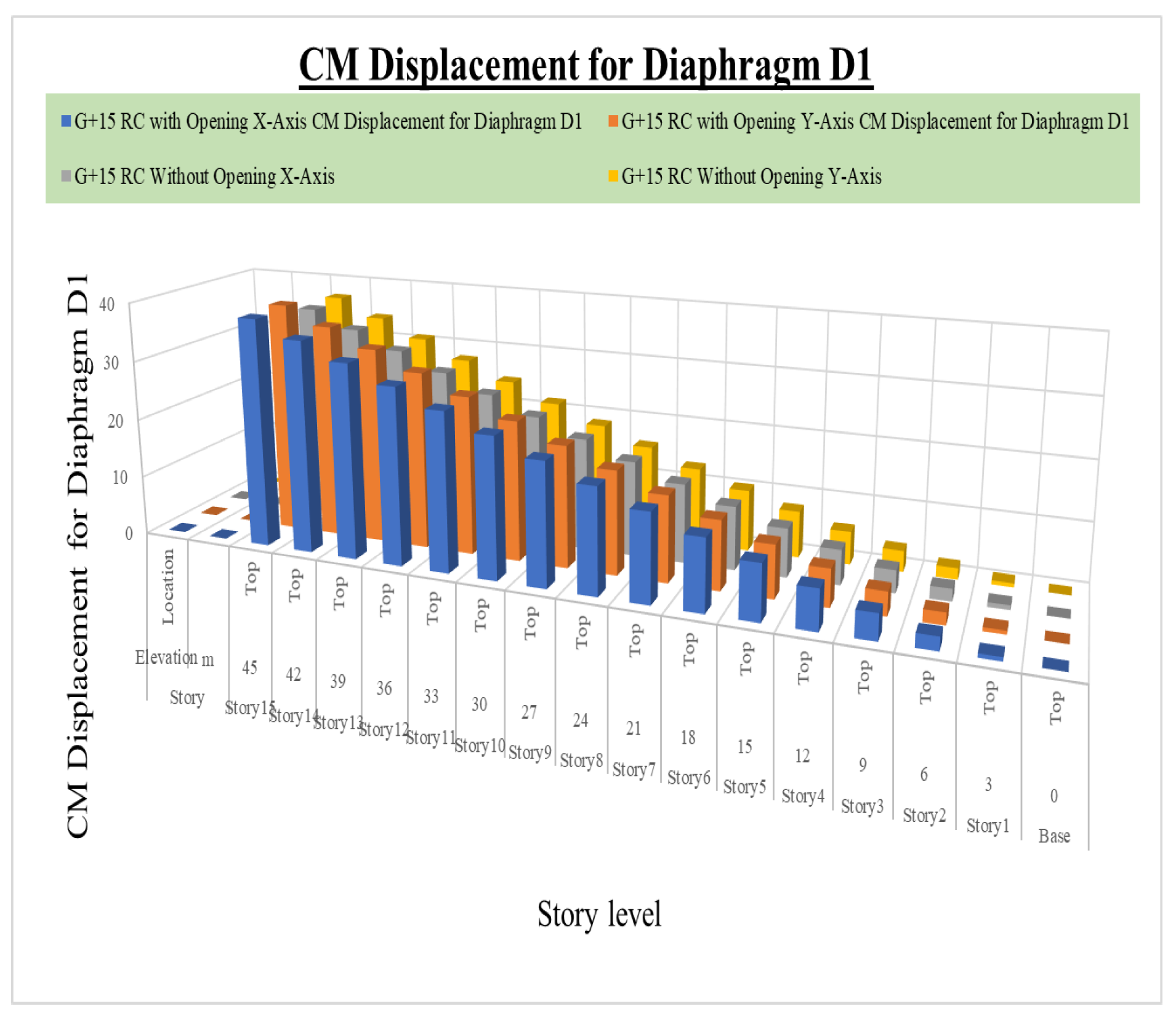
Figure 7 shows the CM displacement for diaphragm D1 for a 15-story structure with and without a shear wall opening response spectrum analysis outputs. From the results, it can be observed that the CM displacement for diaphragm D1 obtained by a shear wall with the opening is higher than that obtained by a shear wall without an opening for all stories. Shear wall with opening analysis gives a maximum of 15% in the X-direction and 12.38% in the Y-direction as higher results at the location of story 4. It can also be noticed that the percentage difference in CM displacement for diaphragm D1 calculated with and without shear wall openings decreases with the increase in height of the structure in both directions. This gives an excellent indication that for high-rise buildings the effect of openings might not be that much compared to low- and mid-rise buildings.
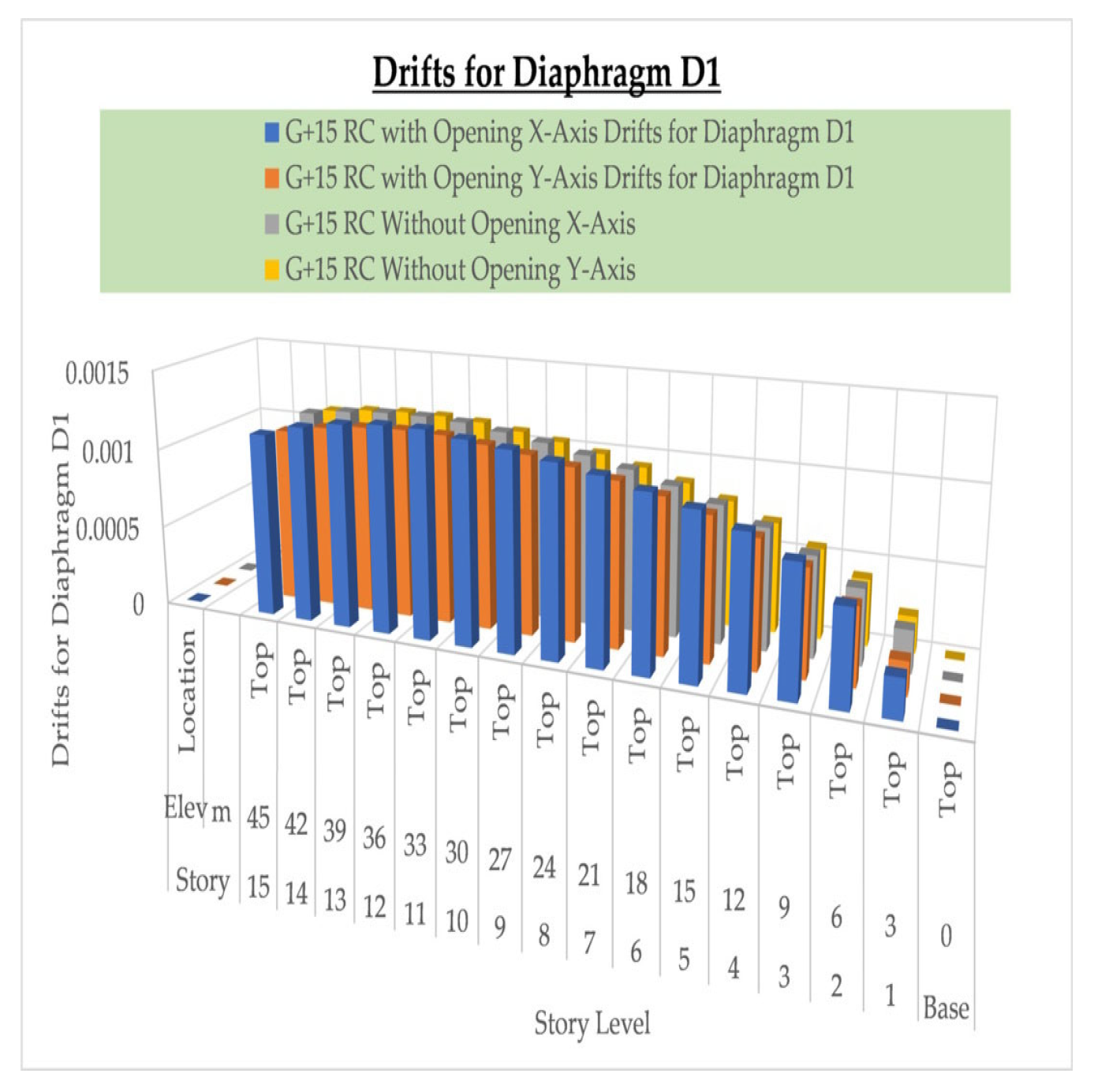
Figure 8 shows the drifts for diaphragm D1 for the 15-story structure with and without shear wall opening response spectrum dynamic analysis global responses. From the results, it can be observed that the drifts for diaphragm D1 obtained by a shear wall with the opening is higher than that obtained by a shear wall without an opening for all stories. Shear wall with opening analysis gives 27.39% in the X-direction and 17.23% in the Y-direction as higher results. It can also be noticed that the difference in drifts for diaphragm D1 calculated with and without a shear wall opening decreases with the increase in height of the structure in both directions. This gives an excellent indication that for high-rise buildings the effect of openings might not be that much compared to low- and mid-rise buildings.
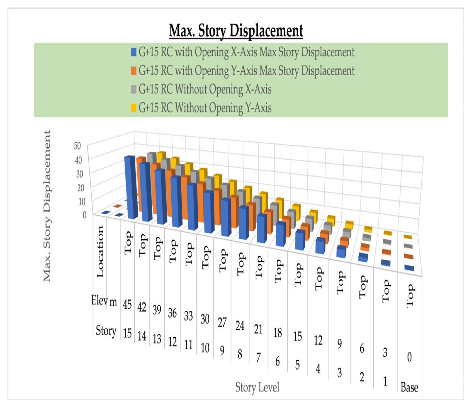
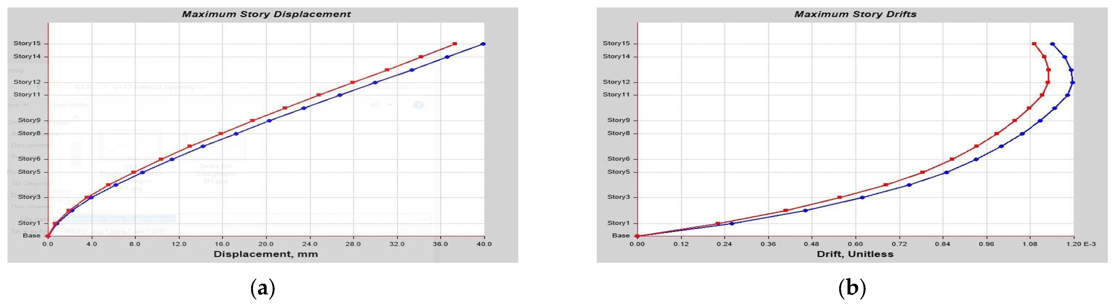
Figure 9 shows the max story displacement for the 15-story structure with and without a shear wall opening response spectrum analysis global responses. From the results it can be observed that the max story displacement obtained by a shear wall with an opening is higher than that obtained by a shear wall without an opening for all stories. Shear wall with opening analysis gives a maximum of 21.13% in the X-direction and 13.33% in the Y-direction as higher results in story 4. It can also be noticed that the percentage difference in max story displacement calculated with and without shear wall openings decreases with the increase in height of the structure in both directions. This gives an excellent indication that for high-rise buildings the effect of openings might not be that much compared to low- and mid-rise buildings.
Figure 10 shows the max story drifts for the 15-story structure with and without a shear wall opening response spectrum dynamic analysis results. From the results it can be observed that the max story drifts obtained by a shear wall with an opening is higher than that obtained by a shear wall without an opening for all stories. Shear wall with opening analysis gives 27.39% in the X-direction and 17.23% in the Y-direction as higher results. It can also be noticed that the percentage difference in max story drifts calculated with and without shear wall openings decreases with the increase in height of the structure in both directions. This gives an excellent indication that for high-rise buildings the effect of openings might not be that much compared to low- and mid-rise buildings.
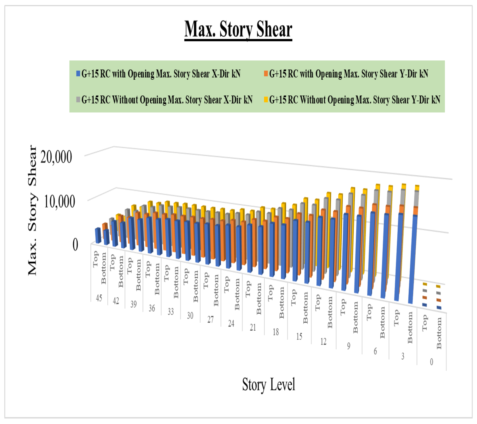
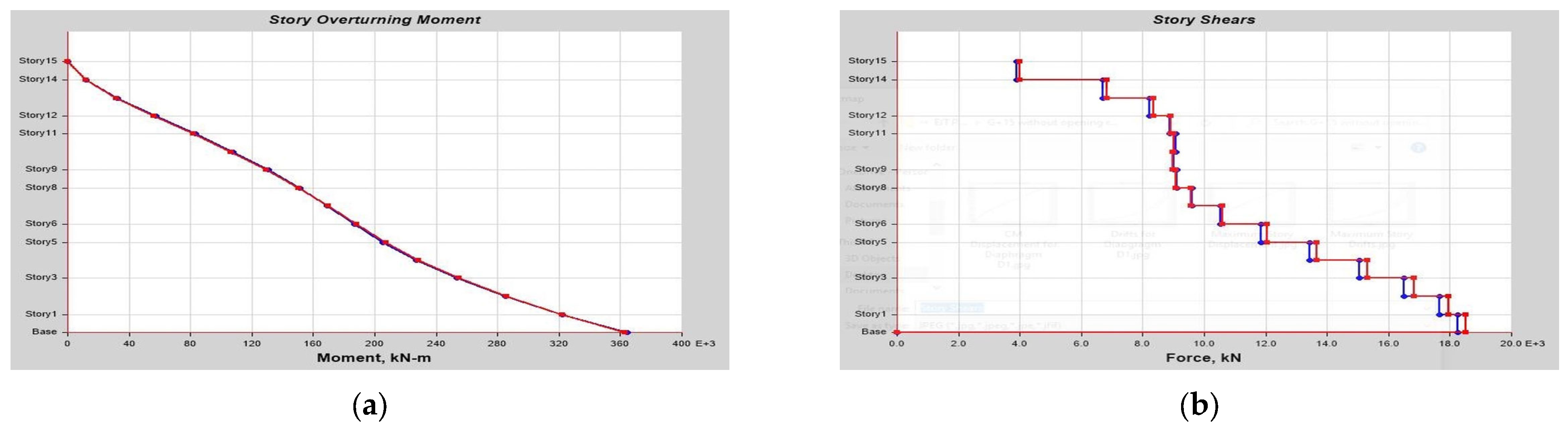
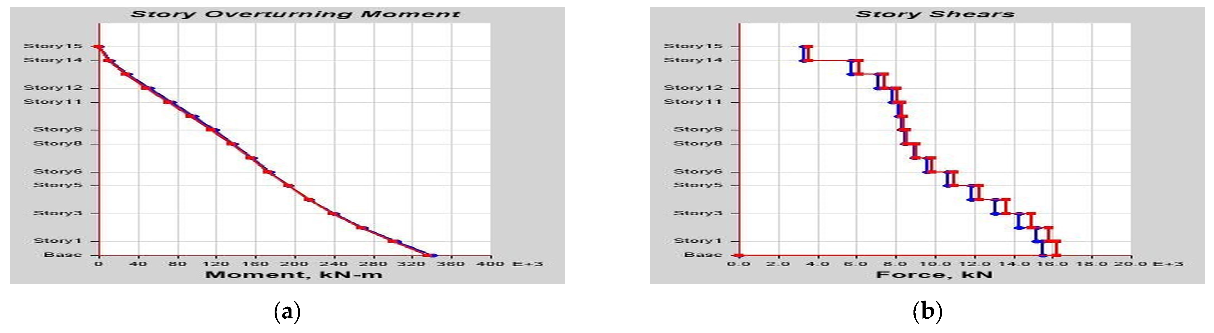
Figure 11 shows the max story shear for the 15-story structure with and without a shear wall opening response spectrum dynamic analysis results. From the results, it can be observed that the max story shear obtained by a shear wall with an opening is lower than that obtained by a shear wall without an opening for all stories. Shear wall with opening analysis gives 15.03% in the X-direction and 12.7% in the Y-direction as lower results. It can also be noticed that the difference in max story shear calculated with and without shear wall openings increases with the increase in height of the structure in both directions.
From the 15-story structure with and without a shear wall opening response spectrum dynamic analysis results, it can be observed that the overturning moment obtained by a shear wall with an opening is lower than that obtained by a shear wall without an opening for all stories. Shear wall with opening analysis gives 10.64% in the X-direction and 14.71% in the Y-direction as lower results. It can also be noticed that the difference in overturning moment calculated with and without a shear wall opening decreases with the increase in height of the structure in both directions. This gives an excellent indication that for high-rise buildings the effect of openings might not be that much compared to low- and mid-rise buildings.
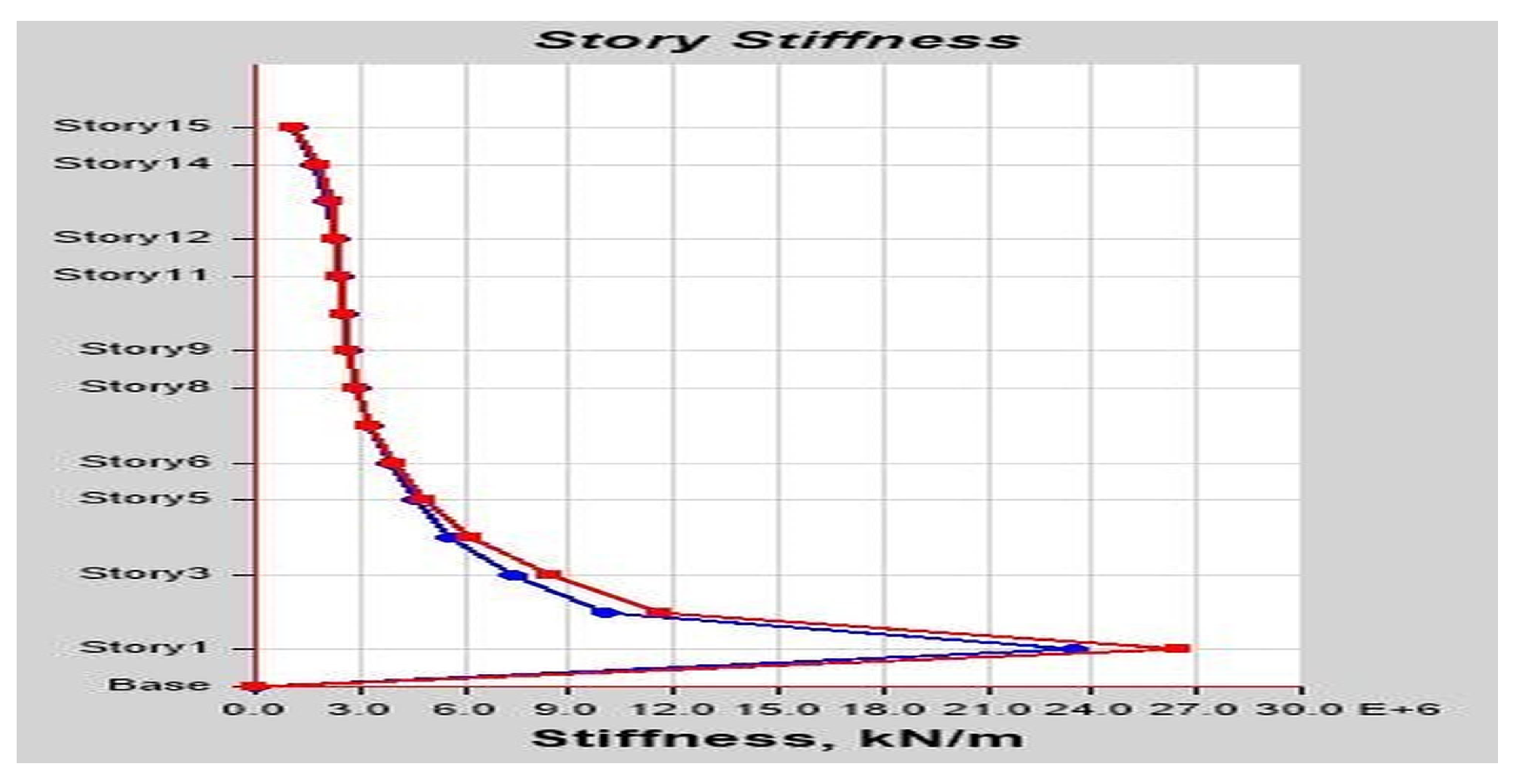
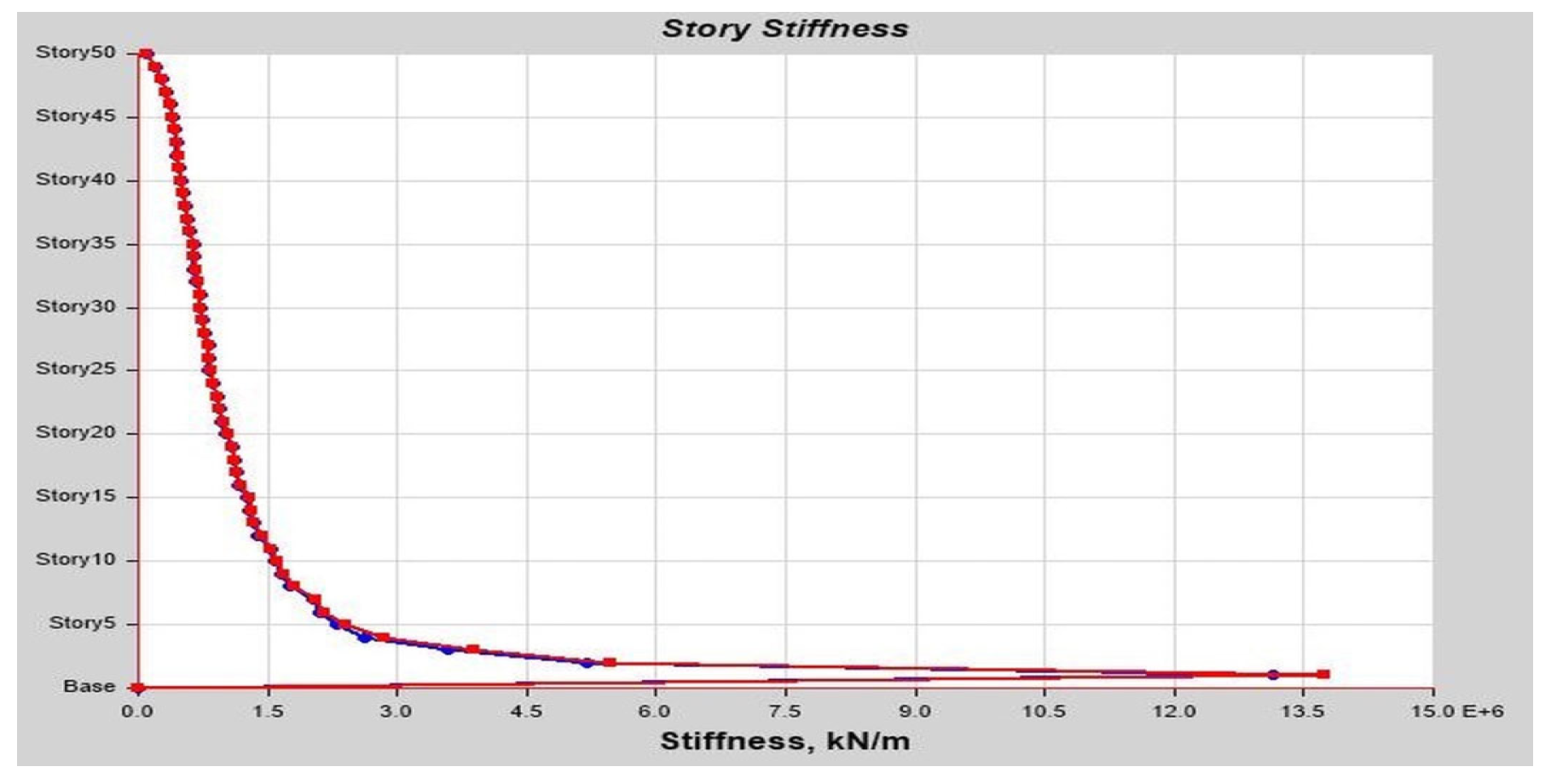
From the story stiffness for the 15-story structure with and without a shear wall opening response spectrum dynamic analysis results, it can be observed that the story stiffness obtained by a shear wall with an opening is lower than that obtained by a shear wall without an opening for all stories. Shear wall with opening analysis gives 25.48% in the X-direction and 20.59% in the Y-direction as lower results at story 2. It can also be noticed that the difference in story stiffness calculated with and without a shear wall opening varies with the increase in height of the structure in both directions.
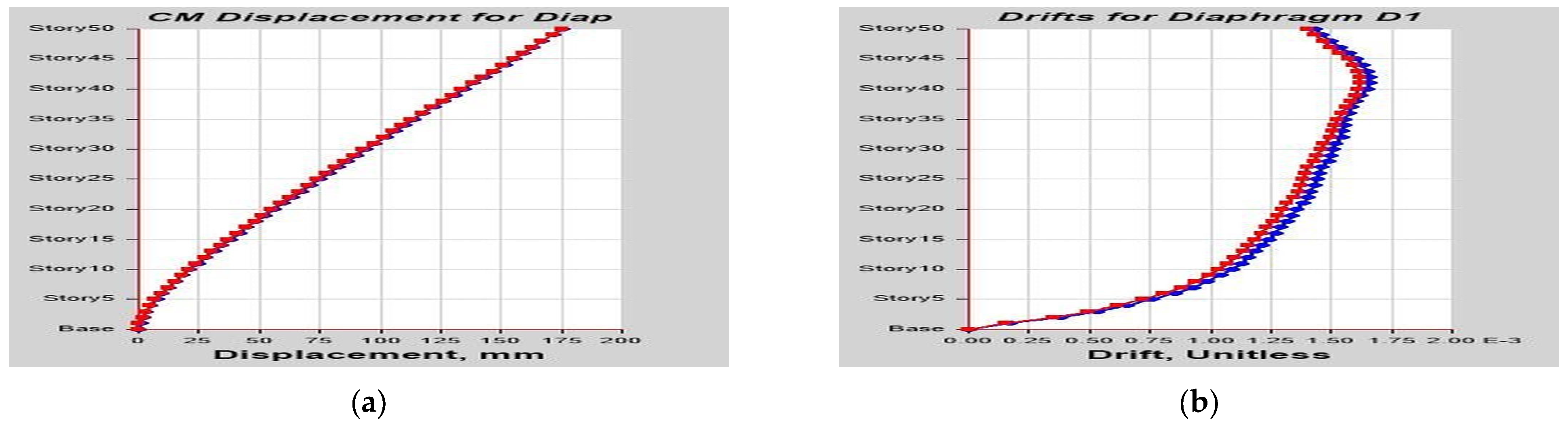
From the CM displacement for diaphragm D1 for the 50-story structure with and without a shear wall opening and framed structure response spectrum dynamic analysis global results, it can be observed that the CM displacement for diaphragm D1 obtained by a shear wall with an opening is higher than that obtained by a shear wall without an opening for all stories. Shear wall with opening analysis of case-1 gives 5.45% in the X-direction and 4.83% in the Y-direction as higher results. Case-2 gives 9.33% in the X-direction and 8.19% in the Y-direction as higher results. Case-3 gives 20.36% in the X-direction and 18.03% in the Y-direction as higher results. Case-4 gives a surprising result that for a framed structure the CM displacement of the bottom part of the structure is extremely high compared with the case-5 building with a shear wall without an opening with 36.434% in the X-direction and 44.54% in the Y-direction as higher results. At the same time, case-4 gives a surprising result that for a framed structure the percentage difference for displacement for the upper part of the structure is extremely low compared with the case-5 building with a shear wall without an opening with 14.61% in the X-direction and 12.43% in the Y-direction as lower results at story 30. It can also be noticed that the difference in percentage of CM displacement for diaphragm D1 calculated with and without a shear wall opening decreases with the increase in height of the structure in both directions. This gives an excellent indication that for high-rise buildings introducing shear walls and openings is not the final and only solution for seismic-prone areas. We have to look for other advanced lateral force-resisting systems such as viscous damping and other relevant technologies.
From the drifts for diaphragm D1 for the 50-story structure with and without a shear wall opening and framed structure response spectrum dynamic analysis global results it can be observed that the drifts for diaphragm D1 obtained by a shear wall with an opening is higher than that obtained by a shear wall without an opening for all stories. Shear wall with opening analysis of case-1 gives 7.44% in the X-direction and 6.06% in the Y-direction as higher results. Case-2 gives 12.23% in the X-direction and 9.82% in the Y-direction as higher results. Case-3 gives 34.96% in the X-direction and 24.31% in the Y-direction as higher results. Case-4 gives a surprising result that for a framed structure the drifts for diaphragm D1 of the bottom part of the structure are extremely high compared with the case-5 building with a shear wall without an opening with 33.24% in the X-direction and 45.66% in the Y-direction as higher results. At the same time, case-4 gives a surprising result that for a framed structure the percentage difference for drifts for diaphragm for the upper part of the structure Is extremely low compared with the case-5 building with a shear wall without an opening with 25.09% in the X-direction and 20.7% in the Y-direction as lower results at story 30. It can also be noticed that the difference in the percentage of drifts for diaphragm D1 calculated with and without a shear wall opening decreases with the increase in height of the structure in both directions. This gives an excellent indication that for high-rise buildings introducing shear walls and openings is not the final and only solution for seismic-prone areas. We have to look for other advanced lateral force-resisting systems such as viscous damping and other relevant technologies.
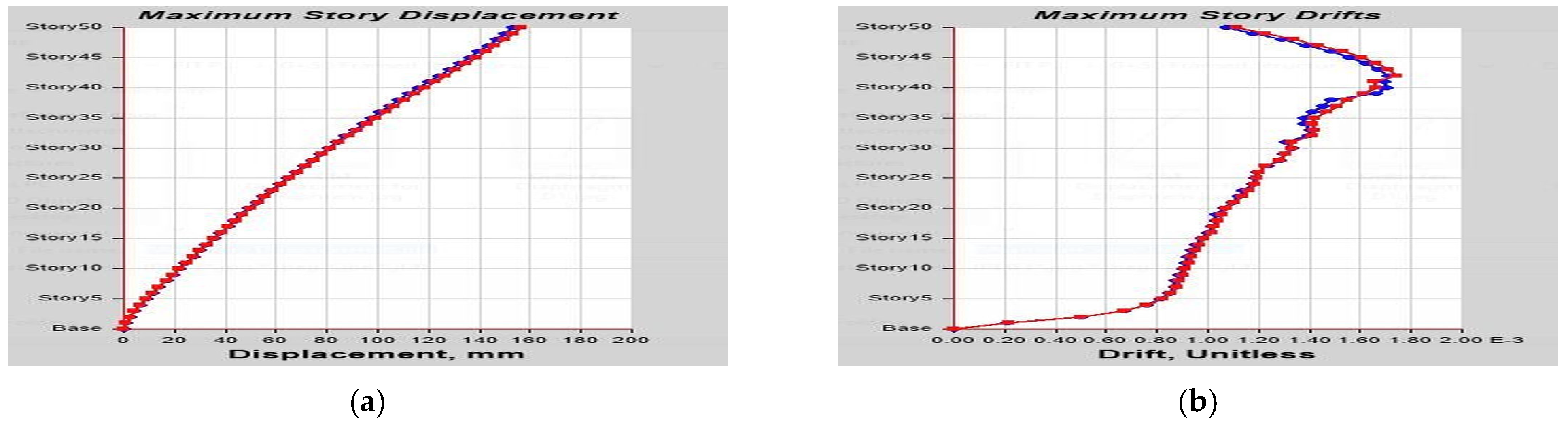
From the max story displacement for the 50-story structure with and without a shear wall opening and framed structure response spectrum dynamic analysis results, it can be observed that the max story displacement obtained by a shear wall with an opening is higher than that obtained by a shear wall without an opening for all stories. Shear wall with opening analysis of case-1 gives 6.51% in the X-direction and 5.16% in the Y-direction as higher results. Case-2 gives 10.58% in the X-direction and 8.24% in the Y-direction as higher results. Case-3 gives 26.11% in the X-direction and 18.76% in the Y-direction as higher results. Case-4 gives a surprising result that for a framed structure the max story displacement of the bottom part of the structure is extremely high compared with the case-5 building with a shear wall without an opening with 31.28% in the X-direction and 44.25% in the Y-direction as higher results. At the same time, case-4 gives a surprising result that for a framed structure the percentage difference for the max story displacement for the upper part of the structure is extremely low compared with the case-5 building with a shear wall without an opening with 17.51% in the X-direction and 12.44% in the Y-direction as lower results at story 29. It can also be noticed that the difference in the percentage of max story displacement calculated with and without shear wall openings decreases with the increase in height of the structure in both directions. This gives an excellent indication that for high-rise buildings introducing a shear wall and openings is not the final and only solution for seismic-prone areas. We have to look for other advanced lateral force-resisting systems such as viscous damping and other relevant technologies.
From the max story drifts for the 50-story structure with and without a shear wall opening and framed structure response spectrum dynamic analysis results, it can be observed that the max story drifts obtained by a shear wall with an opening are higher than those obtained by a shear wall without an opening for all stories. Shear wall with opening analysis of case-1 gives 7.44% in the X-direction and 7.06% in the Y-direction as higher results. Case-2 gives 12.23% in the X-direction and 9.82% in the Y-direction as higher results. Case-3 gives 34.96% in the X-direction and 24.31% in the Y-direction as higher results. Case-4 gives a surprising result for a framed structure as the max story drifts of the bottom part of the structure are extremely high compared with the case-5 building with a shear wall without an opening with 33.24% in the X-direction and 45.66% in the Y-direction being the highest results. At the same time, case-4 gives a surprising result that for a framed structure the percentage difference for max story drifts for the upper part of the structure is extremely low compared with the case-5 building with a shear wall without an opening with 25.08% in the X-direction and 20.697% in the Y-direction as lower results at story 50. It can also be noticed that the difference in the percentage of max story drifts calculated with and without shear wall openings decreases with the increase in height of the structure in both directions. This gives an excellent indication that for high-rise buildings introducing shear walls and openings is not the final and only solution for seismic-prone areas. We have to look for other advanced lateral force-resisting systems such as viscous damping and other relevant technologies.
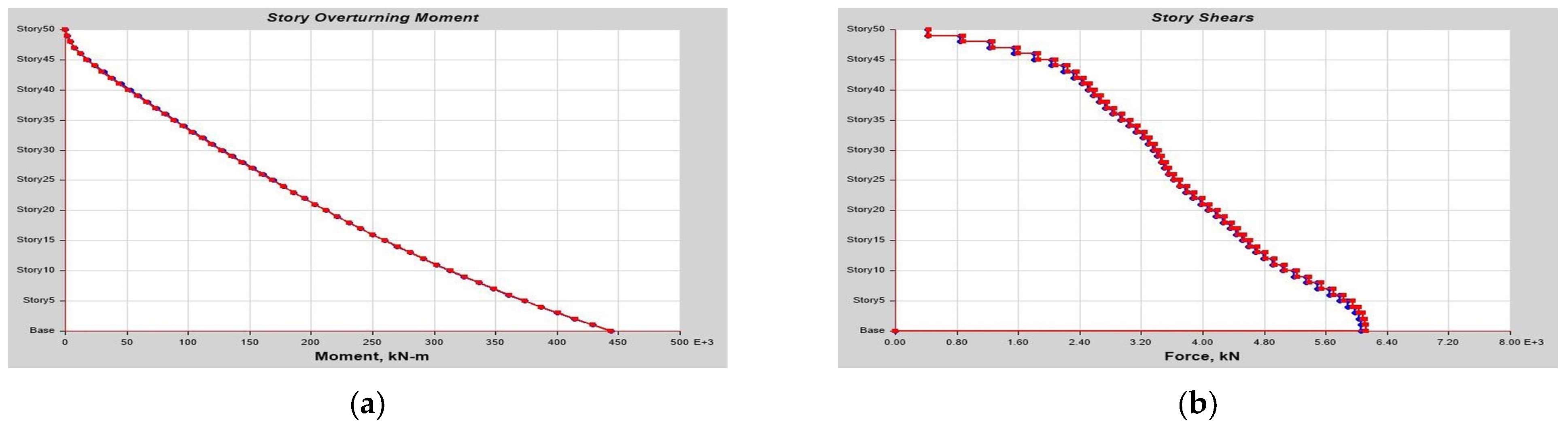
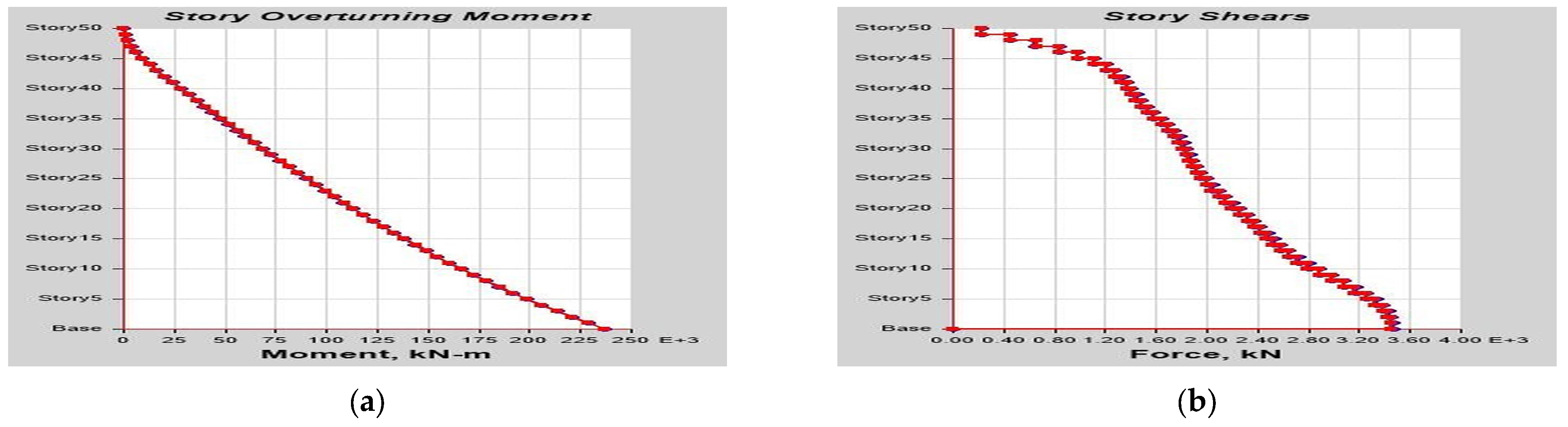
From the max story shear for the 50-story structure with and without a shear wall opening and framed structure response spectrum dynamic analysis results, it can be observed that the max story shear obtained by a shear wall with an opening is lower than that obtained by a shear wall without an opening for all stories. Shear wall with opening analysis of case-1 gives 3.22% in the X-direction and 3.63% in the Y-direction as lower results. Case-2 gives 5.32% in the X-direction and 4.98% in the Y-direction as lower results. Case-3 gives 13.74% in the X-direction and 11.48% in the Y-direction as higher results. Case-4 gives a surprising result that for a framed structure the max story shear of the bottom part of the structure is much lower compared with the case-5 building with a shear wall without an opening provided with 55.52% in the X-direction and 55.91% in the Y-direction as lower results. At the same time, case-4 gives a surprising result that for a framed structure the percentage difference for max story shear for the upper part of the structure is extremely low compared with the case-5 building with a shear wall without an opening. It can also be noticed that the difference in the percentage of max story shear calculated with and without shear wall openings decreases with the increase in height of the structure In both directions. This result gives an excellent indication that for high-rise buildings the effect of introducing shear wall can enhance the shear capacity of the building by over 50% more than over-framed structures, which is extremely important in earthquake-prone areas.
From the overturning moment for the 50-story structure with and without s shear wall opening and framed structure response spectrum dynamic analysis results it can be observed that the overturning moment obtained by a shear wall with an opening is lower than that obtained by a shear wall without an opening for all stories. Shear wall with opening analysis of case-1 gives 3.53% in the X-direction and 3.74% in the Y-direction as lower results. Case-2 gives 4.85% in the X-direction and 5.198% in the Y-direction as lower results. Case-3 gives 11.54% in the X-direction and 13.68% in the Y-direction as lower results. Case-4 gives a surprising result that for a framed structure the overturning moment of the bottom part of the structure is much lower compared with the case-5 building with a shear wall without an opening with 55.91% in the X-direction and 55.53% in the Y-direction as lower results. At the same time, case-4 gives a surprising result that for a framed structure the percentage difference for the overturning moment for the upper part of the structure is extremely low compared with the case-5 building with a shear wall without an opening. It can also be noticed that the difference in percentage of the overturning moment calculated with and without shear wall openings decreases with the increase in height of the structure in both directions. This result gives an excellent indication that for high-rise buildings the effect of introducing a shear wall can enhance the moment capacity of the building by over 50% more than over-framed structures, which is extremely important in earthquake-prone areas.
From the story stiffness for the 50-story structure with and without a shear wall opening and framed structure response spectrum dynamic analysis results, it can be observed that the story stiffness obtained by a shear wall with an opening is lower than that obtained by a shear wall without an opening for all stories. Shear wall with opening analysis of case-1 gives 10.3% in the X-direction and 10.45% in the Y-direction as lower results. Case-2 gives 12.03% in the X-direction and 12.07% in the Y-direction as lower results. Case-3 gives 22% in the X-direction and 17.37% in the Y-direction as lower results. Case-4 gives a surprising result that for a framed structure story stiffness of the bottom part of the structure is much lower compared with the case-5 building with a shear wall without an opening with 63.19% in the X-direction and 63.4% in the Y-direction as lower results. At the same time, case-4 gives a surprising result that for a framed structure the percentage difference for story stiffness for the upper part of the structure is extremely low compared with the case-5 building with a shear wall without an opening. It can also be noticed that the difference in the percentage of story stiffness calculated with and without shear wall openings decreases with the increase in height of the structure in both directions. This result gives an excellent indication that for high-rise buildings the effect of introducing a shear wall can enhance the stiffness capacity of the building by over 63% more than over-framed structures, which is extremely important in earthquake-prone areas. The result also gives an excellent indication that for high-rise buildings the effect of introducing a shear wall can enhance the moment capacity of the building by over 50% more than over-framed structures, which is extremely important in earthquake-prone areas.

5. Conclusions

From intensive analysis and study of case-1 and case-2 for 15-story RC buildings and case-1–5 for 50-story buildings with a type-I response spectrum as per ES8-15 corresponding to Eurocode 8-2004 standards (based on EN 1998-1) [54] for seismic code recommendations, it is concluded that the overall performance of the building was enhanced by the introduction of a shear wall. Case-4 gives a surprising result that for a framed structure the story stiffness of the bottom part of the structure is much lower compared with the case-5 building with a shear wall without an opening with 63.19% in the X-direction and 63.4% in the Y-direction as lower results. At the same time, case-4 gives a surprising result that for a framed structure the percentage difference for story stiffness for the upper part of the structure is extremely low compared with the case-5 building with a shear wall without an opening. It can also be noticed that the difference in the percentage of story stiffness calculated with and without shear wall openings decreases with the increase in height of the structure in both directions. This result gives an excellent indication that for high-rise buildings the effect of introducing a shear wall can enhance the stiffness capacity of the building by over 63% more than over-framed structures, which is extremely Important In earthquake-prone areas. The result also gives an excellent indication that for high-rise buildings the effect of introducing a shear wall can enhance the moment and shear capacity of the building by over 50% more than over-framed structures, which is extremely important in earthquake-prone areas.
Case-4 gives a surprising result that for a framed structure the max story drifts of the bottom part of the structure are extremely high compared with the case-5 building with a shear wall without an opening with 33.24% in the X-direction and 45.66% in the Y-direction being the higher results. At the same time, case-4 gives a surprising result that for a framed structure the percentage difference for max story drifts for the upper part of the structure is extremely low compared with the case-5 building with the shear wall without an opening with 25.08% in the X-direction and 20.697% in the Y-direction as lower results at story 50. It can also be noticed that the difference in the percentage of max story drifts calculated with and without shear wall openings decreases with the increase in height of the structure in both directions. This gives an excellent indication that for high-rise buildings introducing shear walls and openings is not the final and only solution for seismic-prone areas. It is very important to look for other advanced lateral force-resisting systems such as viscous damping and other relevant technologies. It is also concluded that the total deflection of the building is reduced if the shear wall opening is at a higher story. The size and location of the shear wall opening have a tremendous effect on the overall performance of a structure. In general, the story shear, stiffness, drift, overturning moment, and shear force parameters were higher for structures with shear walls, hence it is concluded that the introduction of shear walls with appropriate opening size and location is extremely important in earthquake-prone areas.

Author Contributions

Conceptualization, V.W.Y.T., A.C.J.E. and M.A.; methodology, V.W.Y.T., A.C.J.E. and M.A.; software, M.A.; validation, formal analysis, V.W.Y.T., A.C.J.E. and M.A.; investigation, V.W.Y.T., A.C.J.E. and M.A.; resources, V.W.Y.T., A.C.J.E. and M.A.; data curation, V.W.Y.T., A.C.J.E. and M.A.; writing—original draft preparation, M.A.; writing—review and editing, V.W.Y.T., A.C.J.E. and M.A.; visualization, V.W.Y.T., A.C.J.E. and M.A.; supervision, V.W.Y.T., A.C.J.E. and M.A.; project administration, V.W.Y.T., A.C.J.E. and M.A. All authors have read and agreed to the published version of the manuscript.

Funding

This research received no external funding.

Data Availability Statement

The data presented in this study are available on request from the corresponding author. The data are not publicly available due to EIT privacy policy.

Acknowledgments

The authors extend their deepest gratitude to the Engineering Institute of Technology for their great support.

Conflicts of Interest

The authors declare no conflict of interest.

Appendix A

Figure A1. Target Response spectrum as per ES EN 1998-1:2015 [54].
Buildings 13 01303 g0a1
Figure A2. Shape of the elastic Response Spectrum as per ES EN 1998-1:2015.
Buildings 13 01303 g0a2
Table A1. Elastic response spectra as per ES EN 1998-1:2015.
Ground TypeSTB(S)TC(S)TD(S)
A1.00.050.251.2
B1.350.050.251.2
C1.50.100.251.2
D1.80.100.301.2
E1.60.050.251.2
Table A2. Values of the parameters describing the recommended Type-II elastic response spectra as per ES EN 1998-1:2015.
Ground TypeSTB(S)TC(S)TD(S)
A1.00.150.42.0
B1.20.150.52.0
C1.150.200.62.0
D1.350.200.82.0
E1.40.150.52.0

Appendix B

ETABS Output Result.
G + 15 ETABS Output Result for Shear Wall Without Opening.
Figure A3. (a) CM Displacement for Diaphragm D1; (b) Drift for Diaphragm D1.
Buildings 13 01303 g0a3
Figure A4. (a) Maximum Story Displacement; (b) Maximum Story Drifts.
Buildings 13 01303 g0a4
Figure A5. (a) Story Overturning Moment; (b) Story Shear.
Buildings 13 01303 g0a5
Figure A6. Story Stiffness.
Buildings 13 01303 g0a6
G + 15 ETABS Output Result for Shear Wall With Opening.
Figure A7. (a) CM Displacement for Diaphragm D1; (b) Drift for Diaphragm D1.
Buildings 13 01303 g0a7
Figure A8. (a) Maximum Story Displacement; (b) Maximum Story Drifts.
Buildings 13 01303 g0a8
Figure A9. (a) Story Overturning Moment; (b) Story Shear.
Buildings 13 01303 g0a9
Figure A10. Story Stiffness.
Buildings 13 01303 g0a10
G + 50 ETABS Output Result for Shear Wall Without Opening.
Figure A11. (a) CM Displacement for Diaphragm D1; (b) Drift for Diaphragm D1.
Buildings 13 01303 g0a11
Figure A12. (a) Maximum Story Displacement; (b) Maximum Story Drifts.
Buildings 13 01303 g0a12
Figure A13. (a) Story Overturning Moment; (b) Story Shear.
Buildings 13 01303 g0a13
Figure A14. Story Stiffness.
Buildings 13 01303 g0a14
G + 50 ETABS Output Result for Shear Wall With Opening Case-1.
Figure A15. (a) CM Displacement for Diaphragm D1; (b) Drift for Diaphragm D1.
Buildings 13 01303 g0a15
Figure A16. (a) Maximum Story Displacement; (b) Maximum Story Drifts.
Buildings 13 01303 g0a16
Figure A17. (a) Story Overturning Moment; (b) Story Shear.
Buildings 13 01303 g0a17
Figure A18. Story Stiffness.
Buildings 13 01303 g0a18
G + 50 ETABS Output Result for Shear Wall With Opening Case-2.
Figure A19. (a) CM Displacement for Diaphragm D1; (b) Drift for Diaphragm D1.
Buildings 13 01303 g0a19
Figure A20. (a) Maximum Story Displacement; (b) Maximum Story Drifts.
Buildings 13 01303 g0a20
Figure A21. (a) Story Overturning Moment; (b) Story Shear.
Buildings 13 01303 g0a21
Figure A22. Story Stiffness.
Buildings 13 01303 g0a22
G + 50 ETABS Output Result for Shear Wall With Opening Case-3.
Figure A23. (a) CM Displacement for Diaphragm D1; (b) Drift for Diaphragm D1.
Buildings 13 01303 g0a23
Figure A24. (a) Maximum Story Displacement; (b) Maximum Story Drifts.
Buildings 13 01303 g0a24
Figure A25. (a) Story Overturning Moment; (b) Story Shear.
Buildings 13 01303 g0a25
Figure A26. Story Stiffness.
Buildings 13 01303 g0a26
G + 50 ETABS Output Result for G + 50 Framed Structure Case-4.
Figure A27. (a) CM Displacement for Diaphragm D1; (b) Drift for Diaphragm D1.
Buildings 13 01303 g0a27
Figure A28. (a) Maximum Story Displacement; (b) Maximum Story Drifts.
Buildings 13 01303 g0a28
Figure A29. (a) Story Overturning Moment; (b) Story Shear.
Buildings 13 01303 g0a29
Figure A30. Story Stiffness.
Buildings 13 01303 g0a30

References

  1. Lu, X.; Xie, L.; Guan, H.; Huang, Y.; Lu, X. A shear wall element for nonlinear seismic analysis of super-tall buildings using OpenSees. Finite Elem. Anal. Des. 2015, 98, 14–25. [Google Scholar] [CrossRef]
  2. Samadzad, O.E.S.E.M.; Mirghaderi, S.R. Study of Structural RC Shear Wall System in a 56-Story RC Tall Building. In Proceedings of the 14th world conference earthquake engineering, Beijing, China, 12–17 October 2008. [Google Scholar]
  3. Morkhade, S.; Mashaan, N.S.; Eldirderi, M.M.A.; Khedher, K.M. Modelling of Cyclic Load Behaviour of Smart Composite Steel-Concrete Shear Wall Using Finite Element Analysis. Buildings 2022, 12, 850. [Google Scholar]
  4. Pei, S.; Popovski, M. Seismic design of a multi-story cross laminated timber building based on component level testing seismic design of a multi-story cross laminated timber building based on component level. In Proceedings of the World Conference on Timber Engineering, Auckland, New Zealand, 15–19 July 2012. [Google Scholar]
  5. Gergely, L.; Deierlein, G.G.; Miranda, E.; Liel, A.B.; Tipping, S. Seismic performance assessment of steel corrugated shear wall system using non-linear analysis. JCSR 2013, 85, 48–59. [Google Scholar] [CrossRef]
  6. Hassan, A.; Pal, S. Effect of soil condition on seismic response of isolated base buildings. Int. J. Adv. Struct. Eng. 2018, 10, 249–261. [Google Scholar] [CrossRef]
  7. Pal, S.; Hassan, A.; Singh, D. Optimization of base isolation parameters using genetic algorithm. J. Stat. Manag. Syst. 2019, 22, 1207–1222. [Google Scholar] [CrossRef]
  8. Sumana, C.V.; Raghu, M.E.; Harugoppa, E.R. Comparative Study on Fixed base and Base Isolated Buildings on Sloping Ground. Int. J. Innov. Res. Sci. Eng. Technol. 2016, 5, 14955–14971. [Google Scholar]
  9. Fintel, M. Performance of Buildings with Shear Walls in Earthquakes of the Last Thirty Years. PCI J. 1995, 40, 62–80. [Google Scholar] [CrossRef]
  10. Wallace, B.J.W.; Iv, J.H.T.; Member, S. Sesimic Design of RC Structural Walls. Part II: Applications. J. Struct. Eng. 1995, 121, 88–101. Available online: https://www.researchgate.net/publication/245303205_Seismic_Design_of_RC_Structural_Walls_Part_II_Applications (accessed on 5 April 2023). [CrossRef]
  11. Wu, Y.; Kang, D.; Yang, Y. Seismic performance of steel and concrete composite shear walls with embedded steel truss for use in high-rise buildings. Eng. Struct. 2016, 125, 39–53. [Google Scholar] [CrossRef]
  12. Mosoarca, M. Failure analysis of RC shear walls with staggered openings under seismic loads. Eng. Fail. Anal. 2014, 41, 48–64. [Google Scholar] [CrossRef]
  13. Farzampour, A.; Laman, J.A. Behavior prediction of corrugated steel plate shear walls with openings. JCSR 2015, 114, 258–268. [Google Scholar] [CrossRef]
  14. Taranath, B.S. Reinforced Concrete Design of Tall Buildings; CRC Press Taylor & Francis Group: Boca Raton, FL, USA, 2010; ISBN 9781439804803. [Google Scholar]
  15. Galal, K. Recent advancements in retrofit of rc shear walls. In Proceedings of the Fourteenth World Conference on Earthquake Engineering, Beijing, China, 12–17 October 2008; Available online: https://www.iitk.ac.in/nicee/wcee/article/14_12-03-0039.PDF (accessed on 5 April 2023).
  16. Najm, H.M.; Ibrahim, A.M.; Muayad, M.; Sabri, S.; Hassan, A.; Morkhade, S.; Mashaan, N.S.; Eldirderi, M.M.A.; Khedher, K.M. Evaluation and Numerical Investigations of the Cyclic Behavior of Smart Composite Steel—Concrete Shear Wall: Comprehensive Study of Finite Element Model. Materials 2022, 15, 4496. [Google Scholar] [CrossRef] [PubMed]
  17. Zhang, Z.; Wang, F. Experimental Investigation into the Seismic Performance of Prefabricated Reinforced Masonry Shear Walls with Vertical Joint Connections. Appl. Sci. 2021, 11, 4421. [Google Scholar] [CrossRef]
  18. Walls, S. Seismic Fragility Assessment of Columns in a Piloti-Type Building Retrofitted with Additional. Sustainability 2020, 12, 6530. [Google Scholar]
  19. Coccia, S.; Di Carlo, F.; Imperatore, S. Masonry Walls Retrofitted with Vertical FRP Rebars. Buildings 2020, 10, 72. [Google Scholar] [CrossRef]
  20. Procedure, P.; Jeon, S.; Park, J. Seismic Fragility of Ordinary Reinforced Concrete Shear Walls with Coupling Beams Designed Using a Performance-Based Procedure. Appl. Sci. 2020, 10, 4075. [Google Scholar]
  21. Zheng, S.; Yang, W.; Yang, F.; Sun, L.F.; Hou, P.J. Seismic Vulnerability Analysis of RC Core Tube Structure Based on Multivariate Incremental Dynamic Analysis (MIDA) Method. J. Vib. Shock. 2015, 34, 117–123. [Google Scholar]
  22. Coronelli, D.; Martinelli, L.; Mulas, M.G. Pushover analysis of shaking table tests on a RC shear wall. In Proceedings of the 8th International Conference on Structural Dynamics, Leuven, Belgium, 4–6 July 2011. [Google Scholar]
  23. Wang, Q.; Shi, Q.; Tian, H. Experimental study on shear capacity of SRC joints with different arrangement and sizes of cross-shaped steel in column. Steel Compos. Struct. 2023, 21, 267–287. [Google Scholar] [CrossRef]
  24. Lehman, D.E.; Asce, M.; Turgeon, J.A.; Birely, A.C.; Asce, M.; Hart, C.R.; Asce, M.; Marley, K.P.; Kuchma, D.A.; Lowes, L.N.; et al. Seismic Behavior of a Modern Concrete Coupled Wall. J. Struct. Eng. 2013, 139, 1371–1381. [Google Scholar] [CrossRef]
  25. Husain, M.; Eisa, A.S.; Hegazy, M.M. Strengthening of reinforced concrete shear walls with openings using carbon fiber-reinforced polymers. Int. J. Adv. Struct. Eng. 2019, 11, 129–150. [Google Scholar] [CrossRef]
  26. Dou, C.; Jiang, Z.; Pi, Y.; Guo, Y. Elastic shear buckling of sinusoidally corrugated steel plate shear wall. Eng. Struct. 2016, 121, 136–146. [Google Scholar] [CrossRef]
  27. Berman, J.W.; Bruneau, M. Experimental Investigation of Light-Gauge Steel Plate Shear Walls. J. Struct. Eng. 2005, 131, 259–267. [Google Scholar] [CrossRef]
  28. Hechmi, M.; Ouni, E.; Laissy, M.Y.; Ismaeil, M.; Kahla, N. Ben Effect of Shear Walls on the Active Vibration Control of Buildings. Buildings 2018, 8, 164. [Google Scholar] [CrossRef]
  29. Marius, M. Seismic behaviour of reinforced concrete shear walls with regular and staggered openings after the strong earthquakes between 2009 and 2011. Eng. Fail. Anal. 2013, 34, 537–565. [Google Scholar] [CrossRef]
  30. Ibrahim, A.M.; Najem, H.M. The Effect of Infill Steel Plate Thickness on the Cycle Behavior of Steel Plate Shear Walls. Diyala J. Eng. Sci. 2018, 11, 1–6. [Google Scholar] [CrossRef]
  31. Ibrahim, A.M.; Najem, H.M. Influence of Concrete Strength on the Cycle Performance of Composite Steel Plate Shear Walls. Diyala J. Eng. Sci. 2018, 11, 1–7. [Google Scholar] [CrossRef]
  32. Fadhil, H.; Ibrahim, A.; Mahmood, M. Effect of Corrugation Angle and Direction on the Performance of Corrugated Steel Plate Shear Walls. Civ. Eng. J. 2018, 4, 2667–2679. [Google Scholar] [CrossRef]
  33. Unis, H.; Mohammed, A.S.; Faraj, R.H.; Qaidi, S.M.A.; Mohammed, A.A. Case Studies in Construction Materials Compressive strength of geopolymer concrete modified with nano-silica: Experimental and modeling investigations. Case Stud. Constr. Mater. 2022, 16, e01036. [Google Scholar] [CrossRef]
  34. Khan, M.; Cao, M.; Ali, M. Cracking behaviour and constitutive modelling of hybrid fibre reinforced concrete. J. Build. Eng. 2020, 30, 101272. [Google Scholar] [CrossRef]
  35. Scheduling, G. Modeling and Solution Techniques Used for Hydro Generation Scheduling. Water 2019, 11, 1392. [Google Scholar]
  36. Ahmed, H.U.; Mohammed, A.S.; Qaidi, S.M.A.; Faraj, R.H. Compressive strength of geopolymer concrete composites: A systematic comprehensive review, analysis and modeling. Eur. J. Environ. Civ. Eng. 2023, 27, 1383–1428. [Google Scholar] [CrossRef]
  37. Faraj, R.H.; Unis, H.; Ra, S.; Hamah, N.; Ibrahim, D.F.; Qaidi, S.M.A. Performance of Self-Compacting mortars modi fi ed with Nanoparticles: A systematic review and modeling. Clean. Mater. 2022, 4, 100086. [Google Scholar] [CrossRef]
  38. Borra, S.; Nanduri, P.M.B.R.; Raju, S.N. Design Method of Reinforced Concrete Shear Wall Using EBCS. Am. J. Eng. Res. 2015, 4, 31–43. [Google Scholar]
  39. Khan, Q.U.Z.; Ahmad, A.; Tahir, F.; Iqbal, M.A. Effect of Shape of Shear Wall on Performance of Mid-Rise Buildings Under Seismic Loading. Technol. J. Univ. Eng. Technol. Taxila Pak. 2016, 21, 31. [Google Scholar]
  40. Satpute, S.G.; Kulkarni, D.B. Comparative Study of Reinforced Concrete Shear Wall Analysis in Multi-Storeyed Building with Openings by Nonlinear Methods. Int. J. Struct. Civ. Eng. Res. 2013, 2, 183–193. [Google Scholar]
  41. Ram, S.; Az, S.K.; Mohit, M. Effects of Openings on Different Shapes of Shear Wall in RC Buildings; Crimson Publishing: New York, NY, USA, 2021; Volume 3, pp. 1–10. Available online: https://crimsonpublishers.com/cojts/fulltext/COJTS.000563.php#:~:text=The%20strength%20and%20rigidity%20of%20shear%20wall%20decreases%20due%20to,the%20sizes%20of%20openings%20increase (accessed on 5 April 2023).
  42. Krishna, M.; Arunakanthi, D.E. Optimum Location of Different Shapes of Shear Walls in Unsymmetrical High Rise Buildings. Int. J. Eng. Res. Technol. 2014, 3, 1099–1106. [Google Scholar]
  43. Harne, V.R. Comparative Study of Strength of RC Shear Wall at Different Location on Multi-storied Residential Building. Int. J. Civ. Eng. Res. 2014, 5, 391–400. [Google Scholar]
  44. RezaChowdhury, S.; Rahman, M.A.; Islam, M.J.; Das, A.K. Effects of Openings in Shear Wall on Seismic Response of Structures. Int. J. Comput. Appl. 2012, 59, 10–13. [Google Scholar] [CrossRef]
  45. Mohan, A.; Aarathi, S. Comparison of RC Shear Wall with Openings in Regular and Irregular Building. Int. J. Eng. Res. 2017, 6, 471–476. [Google Scholar] [CrossRef]
  46. Gupta, R.; Bano, A. Performance evaluation of various shapes of shear wall using response spectrum analysis. Int. J. Recent Technol. Eng. 2019, 8, 3246–3251. [Google Scholar]
  47. Mandwe, M.H.; Kagale, S.; Jagtap, P.; Patil, K. Seismic Analysis of Multistorey Building with Shear Wall using STAAD Pro; Seismic Analysis of Multistorey Building with Shear Wall using STAAD Pro. Int. J. Eng. Res. Technol. (IJERT) 2021, 10, 706–710. [Google Scholar]
  48. Babu, P.S.; Murali, K. Comparative analysis of G + 25 structure with and without shear walls using ETABS. AIP Conf. Proc. 2022, 2385, 100002. [Google Scholar]
  49. Mahadik, S.; Bhagat, S. Experimental and Numerical Study of Behavior of RC Shear Wall Using Concealed Stiffeners. Jordan J. Civ. Eng. 2022, 16, 193–210. [Google Scholar] [CrossRef]
  50. Altouhami, R.; Mansur, M.; Ali, H.; Suliman, M.; Altlomate, A.; Alashlam, F.A.A. Wind Effect On Difference Shear Wall Position with Different Shape Configuration. In Proceedings of the Third International Conference on Technical Sciences, Tripoli, Liyba, 28–30 November 2020; Available online: https://www.researchgate.net/publication/348755181_Wind_Effect_On_Difference_Shear_Wall_Position_With_Different_Shape_Configuration (accessed on 5 April 2023).
  51. Yadav, D.N.; Rai, A. Study of Wind Load on Tall RC Frame Building with Shear Wall in Coastal Region. J. Civ. Eng. Environ. Technol. 2020, 7, 215–220. Available online: http://www.krishisanskriti.org/Publication.html (accessed on 5 April 2023).
  52. Wei, F.; Chen, H.; Xie, Y. Experimental study on seismic behavior of reinforced concrete shear walls with low shear span ratio. J. Build. Eng. 2022, 45, 103602. [Google Scholar] [CrossRef]
  53. SAP. Static and Dynamic Finite Element Analysis of Structures; Version 19.0; Computers and Structures; ETABS: Berkeley, CA, USA, 2019. [Google Scholar]
  54. ES EN 1998-1:2015; Eurocode 8: Design of Structures for Earthquake Resistance—Part 1: General Rules, Seismic Actions and Rules for Buildings. European Committee for Standardization: Brussels, Belgium, 2015. Available online: https://www.cen.eu/ (accessed on 5 April 2023).
Figure 1. (a) G + 15 shear wall with opening Floor Plan; (b) G + 15 shear wall without opening Floor Plan.
Buildings 13 01303 g001
Figure 2. (a) G + 50 shear wall with opening Floor Plan; (b) G + 50 shear wall without opening Floor Plan.
Buildings 13 01303 g002
Figure 3. (a) G + 50 Framed Structure without shear wall Floor Plan; (b) G + 15 Framed Structure with shear wall Opening 3D Mode.
Buildings 13 01303 g003
Figure 4. (a) G + 15 Framed Structure without shear wall Opening 3D Model; (b) G + 50 shear wall with opening 3D Model Case-1.
Buildings 13 01303 g004
Figure 5. (a) G + 50 shear wall with opening 3D Model Case-2; (b) G + 50 shear wall with opening 3D Model Case-3.
Buildings 13 01303 g005
Figure 6. (a) G + 50 Framed Structure 3D Model Case-4; (b) G + 50 shear wall without opening 3D Model Case-5.
Buildings 13 01303 g006
Figure 7. G + 15 RC with opening X-Axis CM Displacement for Diaphragm D1; G + 15 RC without Opening X-Axis; Linear (G + 15 RC with Opening X-Axis CM Displacement for Diaphragm D1).
Buildings 13 01303 g007
Figure 8. G + 15 RC with opening X-Axis Drifts for Diaphragm D1; G + 15 RC without Opening X-Axis.
Buildings 13 01303 g008
Figure 9. G + 15 RC with opening X-Axis Max Story Displacement; G + 15 RC without Opening X-Axis.
Buildings 13 01303 g009
Figure 10. G + 15 RC with opening X-Axis Max Story Drifts; G + 15 RC with Opening X-Axis Max Story Drifts.
Buildings 13 01303 g010
Figure 11. G + 15 RC with opening X-Axis Max Story Shear; G + 15 RC with Opening X-Axis Max Story Shear.
Buildings 13 01303 g011
Table 1. The 50- and 15-story RC sample building loading detail.
Loading DetailIntensityCode
Dead load2 KN/m2ES8-15
Live load3 KN/m2ES8-15
Wall load on beam12 KN/m2ES8-15
Response spectrumType-IES8-15
Table 2. Sample 15-story RC building details.
Structure TypeIntensityRemark
Fifteen-story moment resisting frame RC45 mES8-15
Floor to floor height3.2 mES8-15
Wall load on beam12 KN/m2ES8-15
Soil typeBES8-15
Damping5%ES8-15
SupportFixed supportES8-15
Beam section0.50 × 0.35 mES8-15
Column section0.4 × 0.40 mES8-15
Wall section0.300 mES8-15
Slab section0.20 mES8-15
Seismic zoneIII (Addis Ababa)ES8-15
Concrete qualityC-30ES8-15
SteelG-60ES8-15
R factor1ES8-15
Table 3. Sample 50-story RC building detail.
Structure TypeIntensityRemark
Fifty-story moment resisting frame RC150 mES8-15
Floor to floor height3.0 mES8-15
Wall load on beam12 KN/m2ES8-15
Soil typeBES8-15
Damping5%ES8-15
SupportFixed supportES8-15
Beam section0.50 × 0.40 mES8-15
Column section1.20 × 1.20 mES8-15
Wall section0.300 mES8-15
Slab section0.20 mES8-15
Seismic zoneIII (Addis Ababa)ES8-15
Concrete qualityC-30ES8-15
SteelG-60ES8-15
R factor1ES8-15
Table 4. Comparison of with and without shear wall opening dynamic analysis results for CM displacement for diaphragm D1 for 15-story structures.
G + 15 RC with OpeningG + 15 RC without OpeningX–Y-Axis Output
Title 3
X-AxisY-AxisX-Axis Y-Axis
CM Displacement for Diaphragm D1CM Displacement for Diaphragm D1
StoryElevationLocationX-AxisY-AxisX-Axis Y-AxisWith vs. Without Shear Wall Opening X-AxisWith vs. Without Shear Wall Opening Y-Axis
m mmmmmmmm%%
Story 1545Top38.4839.01636.62837.041105.0589713105.3319295
Story 1442Top35.6335.9833.6633.96105.85526105.94452
Story 1339Top32.6832.8730.6530.85106.60925106.55084
Story 1236Top29.6629.7227.6327.73107.34964107.16397
Story 1133Top26.6226.5624.6224.64108.10964107.80000
Story 1030Top23.5823.4121.6521.59108.91628108.45298
Story 927Top20.6020.3218.7518.61109.83685109.17879
Story 824Top17.6417.2915.9215.73110.81946109.94661
Story 721Top14.7614.3413.1912.95111.92479110.73965
Story 618Top11.9511.4810.5610.29113.10436111.49737
Story 515Top9.2518.7538.0927.805114.32278112.14606
Story 412Top6.676.2085.7955.524115.09922112.38233
Story 39Top4.293.9233.7483.52114.46104111.44886
Story 26Top2.2172.0042.0341.875108.99705106.88
Story 13Top0.6590.6060.7350.66189.65986391.679273
Base0Top000000
Table 5. Comparison of with and without shear wall opening dynamic analysis drifts for diaphragm D1 results for 15-story structures.
G + 15 RC with OpeningG + 15 RC without OpeningX–Y-Axis Output
Title 3
X-AxisY-AxisX-Axis Y-Axis
Drifts for Diaphragm D1Drifts for Diaphragm D1
StoryElevationLocationX-AxisY-AxisX-Axis Y-AxisWith vs. Without Shear Wall Opening X-AxisWith vs. Without Shear Wall Opening Y-Axis
m %%
Story 1545Top0.0011420.0010930.0011410.001091100.08764100.18332
Story 1442Top0.0012140.001140.0011750.001118103.31915101.9678
Story 1339Top0.0012580.0011690.0011930.001131105.44845103.35986
Story 1236Top0.001280.001180.0011950.001129107.11297104.51727
Story 1133Top0.0012820.0011740.0011820.001113108.46024105.48068
Story 1030Top0.0012480.0011430.0011470.001078108.80558106.02968
Story 927Top0.0012170.001110.0011070.001038109.93677106.93642
Story 824Top0.0011740.0010660.0010570.000989111.06906107.78564
Story 721Top0.0011270.0010170.0010.000932112.7109.12017
Story 618Top0.0010670.0009560.000930.000865114.73118110.52023
Story 515Top0.0010020.0008810.000850.000784117.88235112.37245
Story 412Top0.0009140.0007830.0007470.000682122.35609114.80938
Story 39Top0.0007860.0006530.0006170.000557127.3906117.23519
Story 26Top0.000580.0004740.0004620.000409125.54113115.89242
Story 13Top0.0002390.0002040.0002590.00022292.27799291.891892
Base0Top000000
Table 6. Comparison of with and without shear wall opening dynamic analysis max story displacement results for 15-story structures.
G + 15 RC with OpeningG + 15 RC without OpeningX–Y-Axis Output
X-AxisY-AxisX-Axis Y-Axis
Max Story DisplacementMax Story Displacement
StoryElevationLocationX-AxisY-AxisX-Axis Y-AxisWith vs. Without Shear Wall Opening X-AxisWith vs. Without Shear Wall Opening Y-Axis
m mmmmmmmm%%
Story 1545Top0.0011420.0010930.0011410.001091100.08764100.18332
Story 1442Top0.0012140.001140.0011750.001118103.31915101.9678
Story 1339Top0.0012580.0011690.0011930.001131105.44845103.35986
Story 1236Top0.001280.001180.0011950.001129107.11297104.51727
Story 1133Top0.0012820.0011740.0011820.001113108.46024105.48068
Story 1030Top0.0012480.0011430.0011470.001078108.80558106.02968
Story 927Top0.0012170.001110.0011070.001038109.93677106.93642
Story 824Top0.0011740.0010660.0010570.000989111.06906107.78564
Story 721Top0.0011270.0010170.0010.000932112.7109.12017
Story 618Top0.0010670.0009560.000930.000865114.73118110.52023
Story 515Top0.0010020.0008810.000850.000784117.88235112.37245
Story 412Top0.0009140.0007830.0007470.000682122.35609114.80938
Story 39Top0.0007860.0006530.0006170.000557127.3906117.23519
Story 26Top0.000580.0004740.0004620.000409125.54113115.89242
Story 13Top0.0002390.0002040.0002590.00022292.27799291.891892
Base0Top000000
Table 7. Comparison of with and without shear wall opening dynamic analysis max story drift results for 15-story structures.
G + 15 RC with OpeningG + 15 RC without OpeningX–Y-Axis Output
X-AxisY-AxisX-Axis Y-Axis
Max Story DriftsMax Story Drifts
StoryElevationLocationX-AxisY-AxisX-Axis Y-AxisWith vs. Without Shear Wall Opening X-AxisWith vs. Without Shear Wall Opening Y-Axis
m %%
Story 1545Top0.0011420.0010930.0011410.001091100.08764100.18332
Story 1442Top0.0012140.001140.0011750.001118103.31915101.9678
Story 1339Top0.0012580.0011690.0011930.001131105.44845103.35986
Story 1236Top0.001280.001180.0011950.001129107.11297104.51727
Story 1133Top0.0012820.0011740.0011820.001113108.46024105.48068
Story 1030Top0.0012480.0011430.0011470.001078108.80558106.02968
Story 927Top0.0012170.001110.0011070.001038109.93677106.93642
Story 824Top0.0011740.0010660.0010570.000989111.06906107.78564
Story 721Top0.0011270.0010170.0010.000932112.7109.12017
Story 618Top0.0010670.0009560.000930.000865114.73118110.52023
Story 515Top0.0010020.0008810.000850.000784117.88235112.37245
Story 412Top0.0009140.0007830.0007470.000682122.35609114.80938
Story 39Top0.0007860.0006530.0006170.000557127.3906117.23519
Story 26Top0.000580.0004740.0004620.000409125.54113115.89242
Story 13Top0.0002390.0002040.0002590.00022292.27799291.891892
Base0Top000000
Table 8. Comparison of with and without shear wall opening dynamic analysis max story shear results for 15-story structures.
G + 15 RC with OpeningG + 15 RC without OpeningX–Y-Axis Output
X-AxisY-AxisX-Axis Y-Axis
Max Story ShearMax Story Shear
StoryElevationLocationX-AxisY-AxisX-Axis Y-AxisWith vs. Without Shear Wall Opening X-AxisWith vs. Without Shear Wall Opening Y-Axis
m KN/mKN/mKN/mKN/m%%
Story 1545Top3328.593554.13902.753977.142385.2882129989.36316158
Bottom3328.593554.13902.753977.142385.2882129989.36316158
Story 1442Top5740.146090.176695.196835.672685.7353658989.09398762
Bottom5740.146090.176695.196835.672685.7353658989.09398762
Story 1339Top7121.567454.538212.48343.68686.7172555689.3434029
Bottom7121.567454.538212.48343.68686.7172555689.3434029
Story 1236Top7831.78046.428886.668917.921388.1287436590.22748384
Bottom7831.78046.428886.668917.921388.1287436590.22748384
Story 1133Top8147.428280.149062.089020.74389.9067474891.78995677
Bottom8147.428280.149062.089020.74389.9067474891.78995677
Story 1030Top8287.478396.549019.598983.281491.8830350493.46846465
Bottom8287.478396.549019.598983.281491.8830350493.46846465
Story 927Top8499.828566.859111.379068.474993.2880274594.46844254
Bottom8499.828566.859111.379068.474993.2880274594.46844254
Story 824Top8928.79009.519594.439561.636893.0613162994.22563718
Bottom8928.79009.519594.439561.636893.0613162994.22563718
Story 721Top96319843.3810,523.110,602.958391.5222896692.83614744
Bottom96319843.3810,523.110,602.958391.5222896692.83614744
Story 618Top10,633.810,973.111,859.112,052.046789.6676241791.04762596
Bottom10,633.810,973.111,859.112,052.046789.6676241791.04762596
Story 515Top11,832.612,256.613,441.913,674.503188.0273695489.63133512
Bottom11,832.612,256.613,441.913,674.503188.0273695489.63133512
Story 412Top13,07313,612.415,036.915,315.279586.9395234188.88092248
Bottom13,07313,612.415,036.915,315.279586.9395234188.88092248
Story 39Top14,251.314,888.116,490.716,823.9986.4201022888.4929972
Bottom14,251.314,888.116,490.716,823.9986.4201022888.4929972
Story 26Top15,147.615,803.517,646.617,964.766485.8385935587.96933368
Bottom15,147.615,803.517,646.617,964.766485.8385935587.96933368
Story 13Top15,517.416,174.818,262.118,527.208584.9704074387.30285299
Bottom15,517.416,174.818,262.118,527.208584.9704074387.30285299
Story 00Top000000
Bottom000000
Table 9. Comparison of with and without shear wall opening dynamic analysis max overturning moment results for 15-story structures.
G + 15 RC with OpeningG + 15 RC without OpeningX–Y-Axis Output
X-AxisY-AxisX-Axis Y-Axis
Overturning MomentOverturning Moment
StoryElevationLocationX-AxisY-AxisX-Axis Y-AxisWith vs. Without Shear Wall Opening X-AxisWith vs. Without Shear Wall Opening Y-Axis
m KN/mKN/mKN/mKN/m%%
Story 1545Top000000
Story 1442Top10,662.39985.768211,931.42711,708.26389.36316285.288214
Story 1339Top28,884.1927,142.43232,391.10331,726.6889.17322185.550812
Story 1236Top50,945.64248,145.2957,128.99655,976.90689.17650486.009202
Story 1133Top74,092.67270,621.03782,905.18981,520.64589.37036886.629635
Story 1030Top96,721.5193,073.904107,701.67106,463.5389.80502687.423279
Story 927Top118,058.8114,607.96130,471.76129,637.4290.48609288.406542
Story 824Top137,854.98134,904.42150,872.21150,594.7391.37201589.581106
Story 721Top156,388.37154,201.21169,283.33169,695.5892.38261490.869317
Story 618Top174,530.84173,160.17186,884.1187,979.4393.38987992.116551
Story 515Top193,572.1192,796.92205,472.61207,006.6494.20822893.135623
Story 412Top214,895.73214,340.56227,018.45228,632.7994.66002993.748828
Story 39Top239,724.97238,907.61253,180.7254,510.6994.68532693.869384
Story 26Top268,892.43267,255.46284,953.79285,632.1394.36352293.566314
Story 13Top302,499.31299,573.61322,395.38322,149.6593.82867292.992066
Base0Top339,778.72335,275.79364,569.2363,315.9393.20006392.28216
Table 10. Comparison of with and without shear wall opening dynamic analysis max story stiffness results for 15-story structures.
G + 15 RC with OpeningG + 15 RC without OpeningX–Y-Axis Output
X-AxisY-AxisX-Axis Y-Axis
Story StiffnessStory Stiffness
StoryElevationLocationX-AxisY-AxisX-Axis Y-AxisWith vs. Without Shear Wall Opening X-AxisWith vs. Without Shear Wall Opening Y-Axis
m KN/mKN/mKN/mKN/m%%
Story 1545Top1,064,320.41,071,233.41,243,754.31,219,373.485.57320187.851138
Story 1442Top1,748,285.51,771,981.32,068,4942,044,364.184.51972886.676402
Story 1339Top2,110,763.62,129,096.72,497,447246,7981.784.5168586.268737
Story 1236Top2,299,928.72,285,950.92,695,627.82,641,784.285.32070786.53057
Story 1133Top2,410,529.32,384,2822,778,993.72710,40786.74108387.967671
Story 1030Top2,515,184.42,486,868.92,848,589.22,786,111.388.29579289.259498
Story 927Top2,655,8182,622,940.22,982,404.32,922,177.489.04956289.759785
Story 824Top2,895,568.62,875,181.63,285,328.53,233,806.788.1363588.910125
Story 721Top3,268,2643,313,154.33,805,207.23,804,871.885.88925387.076636
Story 618Top3,815,8873,953,776.64,597,4554,659,724.182.99998584.850014
Story 515Top4,562,071.34,857,171.15,685,850.55,835,069.980.23551383.241009
Story 412Top5,602,686.96,205,356.47,203,6777,503,307.277.77537782.701617
Story 39Top7,390,724.18,516,175.49,501,555.310,104,99877.78436284.276864
Story 26Top10,066,30411,665,45513,507,64414,689,37974.52301879.414217
Story 13Top23,452,85126,533,46924,809,27227,929,48494.53260495.001644
Base0Top000000
Disclaimer/Publisher’s Note: The statements, opinions and data contained in all publications are solely those of the individual author(s) and contributor(s) and not of MDPI and/or the editor(s). MDPI and/or the editor(s) disclaim responsibility for any injury to people or property resulting from any ideas, methods, instructions or products referred to in the content.

