
Daylight Comfort Performance of a Vertical Fin Shading System: Annual Simulation and Experimental Testing of a Prototype


Faculty of Architecture, Wroclaw University of Science and Technology, Prusa 53/55, 50-317 Wroclaw, Poland
Buildings 2024, 14(3), 571; https://0-doi-org.brum.beds.ac.uk/10.3390/buildings14030571
Submission received: 16 January 2024
/
Revised: 12 February 2024
/
Accepted: 18 February 2024
/
Published: 21 February 2024
(This article belongs to the Special Issue New European Bauhaus (NEB) in Architecture, Construction and Urbanism)
Abstract
:This study aims to develop and evaluate a vertically rotated fin shading system for an energy-efficient, user-friendly office space. The system was designed to protect a 4 × 8 m office room with a south-facing facade from excessive solar radiation and glare. The shading system was modelled and simulated using Rhino/Ladybug 1.6.0 software with Radiance engine, based on real-weather data (*.epw file) for Wrocław, Poland at 51° lat. The simulation calculated the useful daylight illuminance (UDI) for 300–3000 lux and the daylight glare probability (DGP) for ten static and four kinetic variants of the system. The optimal angle of the fin rotation for the static variant was found to be α = 40°. The kinetic variants were activated when the work plane illuminance exceeded 3000 lux, as detected by an internal sensor “A”. The simulation results show that the kinetic system improved the daylight uniformity in the office room, achieving UDI300–3000 values above 80% for more than 40% of the room area. A prototype of the system in a 1:20 scale was built and tested on a testbed at Wrocław University of Science and Technology, using TESTO THL 160 data loggers. The measurements were conducted for a week in early November 2023, and three clear days were selected for analysis. The measurement results indicate that the low solar altitude on clear days causes high illuminance peaks (15–18 Klux) and significant contrast in the room, leading to unsatisfactory DGP values consistent with the simulation outcomes. Therefore, the study concludes that the proposed system may need an additional shading device to prevent glare during periods of low solar altitudes.
1. Introduction
Daylight is essential for human health and well-being but is also subject to regulations and standards. Designers must provide adequate lighting for the tasks performed on the work plane while considering the daylight variability over time. Office spaces are often side-lit with all-glass facades, which create problems of over-illumination, uneven distribution of light, and excessive glare near the facade. At the same time, the illuminance levels in the room’s depth are inadequate.
This paper evaluates a custom-developed shading system that adapts to the changing illuminance levels and channels some daylight into the depth of the office room. The proposed system aims to equalize daylight levels and improve the uniformity of daylight in an office space.
An adaptive facade is a type of facade that can adjust its parameters according to different environmental stimuli. This category encompasses systems that change transparency (e.g., daylight regulation systems), heat storage (phase change material systems, adaptive insulation systems), or air exchange (e.g., double facade). Al Dakheel et al., demonstrated in their review paper that electrochromic glass, which can control its transmittance, is the most common adaptive facade system [1]. Following this finding, the author of the presented paper reviewed the latest electrochromic technologies in a review paper published in the journal Sustainability [2].
A particular type of adaptive facade is the kinetic facade that uses mechanical systems to change the position of its components/elements, usually for shading daylight and controlling illuminance in rooms. The kinetic facade has these benefits: (i) it uses daylight more efficiently, (ii) it distributes daylight to the back of the room, (iii) it reduces energy for artificial lighting, and (iv) it enhances color reproduction due to the natural temperature of light. In addition, as Adriasens states, its “efficacy meets or exceeds that of a fixed system” [3].
Kinetic technologies are essential for meeting the 17 sustainable development goals set by the United Nations, especially goal 11 (sustainable cities and communities) and goal 13 (climate action), by cutting down CO2 emissions [4]. Adaptive facades are in line with not only the U.N. goals but also the postulates of the New European Bauhaus. The proposed shading system is as follows:
- A creative and interdisciplinary project that combines architecture, engineering, and design. It demonstrates how innovative techniques and technologies can create a dynamic and interactive facade that responds to the environment and the users.
- Aligned with the sustainability value of the New European Bauhaus, as it improves the building’s energy efficiency and thermal comfort by using kinetic elements that adjust the light and shade on the facade.
- Consistent with the New European Bauhaus’s aesthetic value, it creates a distinctive and attractive appearance for the building that reflects its function and identity. It enhances the urban landscape’s character and texture by creating diverse visual effects and moods that vary with the time of day, season, weather, or user preference.
- Relevant for the inclusion value of the New European Bauhaus, as it encourages dialogue and collaboration among different stakeholders, such as architects, engineers, designers, builders, owners, and users. In addition, it provides accessibility and affordability for different types of buildings and contexts, as it can be adapted and customized to suit different needs and preferences [5].
1.1. Selected Challenges
Kinetic facades pose particular design challenges. They involve complex design and construction and require user-friendly control systems. The author briefly lists the challenges he encountered in his proposal concerning the existing literature:
- Kinetic facades are usually complex mechanisms with high construction and maintenance costs; only a few kinetic shading systems have been built. A few are in operation, as shown in Figure 1. Different authors address the high cost of kinetic systems. Sadeh et al. claim that “motors drive most kinetic facades, which adds to the maintenance costs; thus, shape memory alloys (SMAs) are investigated as actuators” [6]. The team of Moloney et al. even suggested offsetting part of the cost by “adding value by repurposing the sun screening system as a low-resolution media screen” [7].
- Another challenge that affects shading systems in general is the direction of fins. Alzoubi and Al-Zoubi tested vertical and horizontal shading devices for south-facing facades in a dry climate [8]. Even though the analysis was done for a very different latitude, the results are relevant to this study.
- The design of workspaces considers not only the amount of daylight and glare but also the quality of the view outside, which affects the occupants’ visual comfort. However, kinetic facades, which use movable elements to block daylight during periods of high solar radiation, simultaneously obstruct the view. This poses a significant challenge for the design of kinetic facades, especially when they have to meet specific standards, such as EN 17037 [9], or certification systems, such as LEED v4. Systems that operate in low solar altitudes require special attention, as they face a trade-off between reducing glare and preserving the view.
- Using kinetic shading systems in heating-dominant climates could reduce the exposure to solar energy flux on winter days, resulting in higher heating costs due to the lower greenhouse effect. Shum and Zhong studied this issue extensively in 2023 in the context of five Canadian cities (Vancouver, Edmonton, Toronto, Quebec, and Fairbanks). They did not elaborate on the reduced greenhouse effect; instead, they found that a shading system deployed at night reduced heat loss from the room to the outside due to lower heat radiation and reported that “the overall heating load reduction was less than 5%” [10].
1.2. Objective of the Study
The presented study uses a two-step methodology: simulation and experiment. It proposes methods to (i) simulate annual daylight in different lighting scenarios (Variants 0–13) and (ii) measure the illuminance values based on a prototype that is designed, built, and tested on a testbed under real weather conditions in Wrocław, Poland at 51° lat. N, for three clear days in early November 2023.
This paper’s primary goal is to determine the highest level of useful daylight illuminance (UDI300–3000) that can be achieved using mixed settings of the shading system elements. Additional objectives of this study are to simulate the qualitative metrics, luminance level and daylight glare probability (DGP) and to identify the optimal daylighting scenario to maximize UDI300–3000.
2. State of the Research
The author reviewed current knowledge and practices in the field of kinetic facades. The review provides a comprehensive and critical overview of the existing literature, methods, technologies, and applications, as well as the gaps, challenges, and opportunities for future research and development.
2.1. Review Method and Eligibility Criteria
The literature review data were obtained from international scientific databases (WoS and Scopus—last search 31st of December 2023). The author searched for the “keywords” in the titles and abstracts of related studies. The search strategy for all databases included the papers with the keywords “kinetic facade”, “adaptive facade”, and “daylight”. The analysis focused on the documents with methods that simulated shading elements. Some “snowballing” (the review of the references in the previously reviewed papers) was used too.
The study selection involved several steps. First, the author (MB) screened titles and abstracts to find potential studies. “Adaptive” and “kinetic” facades were a common topic in many studies in building engineering in the last 20 years. The author (MB) reviewed titles and abstracts of records published from 2019 to 2023 and removed duplicates. Then, the same researcher screened the abstracts from 1996 to 2019. The scoping process yielded 85 papers, of which 38 relevant articles were selected for further review. Finally, 31 papers (all cited) were included in the literature review. Table 1 compares different approaches and conclusions by different research teams. The primary scientific method for the literature study was a desk study (P.C. with an internet connection) without any automation tools.
2.2. Adaptive Façade
Kinetic facades are a subset of the broader research problem of adaptive facades, which can change their parameters in response to varying environmental conditions [11]. Adaptive facades typically regulate the energy flow into the room. Previous studies, e.g., by Cecchi et al. (2014), have proposed different types of adaptive facades, such as a facade with a flat water container where fluid with adjustable transparency flows through [12]. Komerska et al. (2015) presented a prototype of a facade with phase change material embedded to control the daylight [13]. A team of Al Dakheel et al. (2017) presented a review paper on different adaptive systems, concluding that electrochromic coatings are the most frequently used type of intelligent glazing [1]. A recent review of 51 case studies of intelligent materials for adaptive facades by Premier (2019) found that shape memory materials are still in the early stage of development [14]. The author published a paper in the journal Sustainability (2021), reviewing the latest electrochromic technologies and finding that most are at the initial stage, often at the scale of small laboratory prototypes [2].
2.3. Kinetic Systems
Since adaptive technologies are still in the early stage of development and application, kinetic systems are a viable alternative to regulate the daylight entering a room. Unlike adaptive systems, kinetic systems use mechanical parts to control the flow of daylight into the room. These parts include flaps, fins, louvres, and retractable rollers that motors or actuators move to screen the daylight. The movement can involve translation, rotation, folding, or a combination of these. One of the first functional kinetic systems was installed in 1988 on the south facade of the Museum of Arab World in Paris (designed by Jean Nouvel, 1987). It consisted of complex diaphragms powered by electric motors. However, the system was prone to malfunction and is currently being restored (see Figure 1).
This chapter reviews previous studies on kinetic facades, a subset of adaptive facades that use mechanical parts to control the daylight flow into a room. Adriaenssens et al. (2014) presented a study of dialectic form-finding of a shading system that consists of a central beam element with two attached flexible shells that bend to adjust the opacity of the facade [3]. The design explores elastic deformations for shape changes, reducing actuation requirements. Chan et al. (2015) analyzed the potential of a multi-sectional facade that uses combinations of three solar protection and light-redirecting devices (light shelves, roller shades, and Venetian blinds) in an integrated manner [15]. The main benefits of this system are lighting energy savings and reduced cooling load due to lower internal heat gain. Wanas et al. (2015) provided an analysis of two types of kinetic facades in the climatic conditions of Egypt, one with rotating shading louvres and another with vertically moving shading louvres [16]. The authors used Rhino/Grasshopper (DIVA plugin) software to describe the shading elements parametrically. They found that using well-studied kinetic louvres increases the percentage of the daylit zone to 63% instead of 53% without shadings. Lee et al. (2016) developed a computational model to evaluate heat transfer and daylight lighting for an external shading device featuring a drop awning with length-angle-length changes [17]. Cimmino et al. (2017) explored the potential of tensegrity structures using the blinking sail solar facade system, which includes folding elements that partially overshadow the facade behind [18]. However, the paper did not provide information on the system’s effectiveness. Sheikh et al. (2019) proposed an adaptive biomimetic facade based on the redwood sorrel plant [19]. The system’s geometry is a rigid origami-like element with folding lines deformed by the actuators working in horizontal and vertical axes. Depending on the requirements, the module can be folded to form vertical and horizontal shading fins. The system is simulated against an existing building, yielding a 27–32% improvement in HVAC and lighting energy.
Grobman et al. (2019) studied vertical, horizontal, and diagonal fins in two kinetic scenarios: (i) seasonal and (ii) adaptive to momentary weather conditions according to LEED standards. They concluded that dynamically adjusted louvres performed significantly better than the other modes of operation (about 6–34% better than the other scenarios in the horizontal louvres) [20]. Damian et al. (2019) presented a heat balance analysis for an 8-story office building in three Romanian cities, with a kinetic shading system commanded by a solar irradiance sensor [21]. They reported annual cooling load reductions with a dynamic system ranging from 36.9 to 42.8%. Luan et al. (2021) published a simulation study of a facade kinetic shading system inspired by the art of origami in the journal Energy [22]. The proposed kinetic shading device was based on a triangle shape, covered by three corrugated panels, that opened the aperture by folding its panels like a paper fan. The proposed design always kept the Annual Sunlight Exposure lower than others, from 9% to 42%, thus reducing the energy required for cooling significantly. Hosseini et al. (2021) presented an extensive review study of various kinetic systems and steering scenarios. They concluded that a generative-parametric and quick-form finding method for responding to climate fluctuation would be a solution for providing more adaptability to dynamic environmental stimuli [23]. Mangkuto et al. (2022) studied four floors in a high-rise building in a tropical climate [24]. The results showed that a static shading system satisfied LEED requirements only for the south and north facades (which were least exposed to direct daylight). Fulfilling LEED requirements on the east and west facades required using an adaptive shading system, using 30 slats for the west and east facades.
Sankaewthong et al. (2022) presented a simulation and an experimental study of a newly designed kinetic twisted facade. They showed that this type of facade had more potential than other building envelope types in terms of filtering beneficial daylight in indoor areas [25]. Moreover, they conducted a small experimental study using a reduced-scale prototype with some measurement data. Globa et al. (2022) presented an analysis of a hybrid kinetic facade, including the fabrication and feasibility evaluation of full-scale prototypes [26]. They provided a detailed life cycle assessment (LCA) study but did not analyze the facade performance. Anzaniyan et al. (2022) surveyed the bio-kinetic facade, which integrates kinetic architecture, biomimicry, and occupants’ visual and thermal comfort [27]. They concluded that the bio-kinetic facade reduced the electric lighting load by about 48%.
2.4. The Most Recent Studies
In addition, the author conducted a literature review of the recent publications on kinetic facades in 2023. Khraisat et al. (2023) reviewed 13 papers and concluded that different kinetic facade systems were highly energy-efficient and effective in attaining desired daylighting within the buildings [28]. Akimov et al., introduced the new metric—facade daylighting performance improvement (FDPI)—and presented a new type of kinetic device showing 43% improvement compared to three existing case studies [29]. Takhmasib et al. (2023) presented the first on-site investigation of an artificial intelligence-integrated 3-dimensional movable kinetic facade. A notable feature of the study is that it was performed at a full scale of 1:1 [30]. Haghighat and Sadeh (2023) presented an innovative parametric design of an automated kinetic building facade that allows pollination using beehives located in the building [31]. Kahramanoglu and Çakıcı Alp (2023) provided daylight analysis based on the Miura-ori origami folding kinetic facade and reported a UDI increase from 61% to 80.75% [32]. Fahmy et al. (2023) presented a system of vertical kinetic fins applicable in regions with clear skies and low solar altitudes. They stated that a kinetic fins system could enhance the daylighting for west-oriented facades [33]. Chuan et al. (2023) presented a study of a kinetic facade inspired by Malaysia’s Siamese culture. Various designs were simulated on a wall measuring 5.3 × 6.0 m with a window-to-wall ratio of 70%. The authors concluded that the “kinetics pattern is able to harvest daylight into the rooms in response to the external environment at any time of the day” [34]. Engin and Dincer (2023) used Grasshopper to analyze multiple variants of kinetic facades using analytical multicriteria decision-making (MCDM) tools and an analytic hierarchy process (AHP) [35]. Alawaysheh et al. (2023) developed a parametric model for adjusting the opening ratios of the kinetic panels. The research revealed several significant results, including the finding that the optimal kinetic system resulted in 20% energy savings and a 31% reduction in daylight illuminance levels [36]. Sharma and Kaushik (2023) evaluated the performance of kinetic shading systems to enhance visual comfort in a composite climate in Gurugram, India [37]. Ningsih et al. (2023) experimented with a hexagonal kinetic facade prototype and showed a 40–50% increase in efficiency rate and 40% radiation reduction when the kinetic module was closed [38]. Taleb and Moarbes (2023) presented a validated simulation study of a folding kinetic facade, which decreased the energy used by 21.3% [39].

Table 1.
The literature review.
| Ref. No. | Authors | Year | Methodology | Research Focus | Research Gap 1 |
|---|---|---|---|---|---|
| subject: adaptive facade | |||||
| [12] | Cecchi et al. | 2014 | experiment | ● flat water container, in which there was fluid with regulated transparency | ● the early stage of research |
| [13] | Komerska et al. | 2015 | experiment | ● facade with phase change material embedded to regulate the daylight | ● inability to regulate the shadingelement |
| [1] | Al Dakheel et al. | 2017 | review paper | ● review paper on different adaptive systems | ● geographical limitation |
| [14] | Pemier | 2019 | review paper | ● review of 51 case studies of intelligent materials used for adaptive facades | |
| [2] | Brzezicki | 2021 | review paper | ● review of the most recent electrochromic technologies | ● most of the presented technologies are at the very introductory stage, below the scale of the prototype |
| subject: kinetic systems | |||||
| [3] | Adriaenssens et al. | 2014 | simulation | ● louvre system designed to protect from ultraviolet radiation over a predefined target ● shape-shifting modular facade system that adapts its opacity in response to environmental fluctuations | ● lack of experimental data |
| [15] | Chan et al. | 2015 | simulation | ● multi-sectional facade, which uses combinations of three solar protection and light-redirecting devices | ● lack of experimental data |
| [16] | Wanas et al. | 2017 | simulation | ● an analysis of two types of kinetic facades in the climatic conditions of Egypt | ● geographical limitation |
| [17] | Lee et al. | 2016 | experiment | ● external shading device featuring a drop awning with length-angle-length changes | |
| [18] | Cimmino et al. | 2017 | ● tensegrity structures, using the system “blinking sail solar facade” | ● the article lacks information on the effectiveness of the system | |
| [19] | Sheikh et al. | 2019 | simulation | ● “adaptive biomimetic facade”, based on the redwood sorrel plant ● yields a 27–32% improvement in HVAC and lighting energy | ● geographical limitation ● prone to a strong wind |
| [20] | Grobman et al. | 2019 | simulation | ● vertical, horizontal, and diagonal fins in two kinetic scenarios: seasonal and adapting to momentary weather conditions according to LEED standards | ● lack of experimental data |
| [21] | Damian et al. | 2020 | simulation | ● heat balance analysis for an eight-story office building in three Romanian cities, with a kinetic shading system | ● no daylight comfort analysis |
| [22] | Luan et al. | 2021 | simulation | ● simulation studies of a facade kinetic shading system inspired by the art of origami | ● geometrically complicated shading element, no proposal of mechanical guidance of fan-like shading fins |
| [23] | Hosseini et al. | 2021 | review paper | ● extensive review study considering many different types of kinetic systems and steering scenarios | |
| [24] | Mangkuto et al. | 2022 | simulation | ● provides a study of four floors in a high-rise building in a tropical climate | ● static shading system satisfies LEED requirements only for south and north facades in the tropical climate |
| [25] | Sankaewthong et al. | 2022 | simulation, experiment | ● simulation and an experimental study of a newly designed kinetic twisted facade ● authors provided a “mini-prototype” of the facade system | |
| [26] | Globa et al. | 2021 | experiment | ● fabrication and feasibility evaluation of a full-scale kinetic facade prototype with some greenery coverage ● including in-depth LCA analysis | ● no daylight comfort analysis |
| [27] | Anzaniyan et al. | 2022 | simulation, experiment | ● provides a study of a bio-kinetic facade modelled on the Lupinus Succulentus plant ● kinetic facade prototype was designed and fabricated | |
| the most recent studies | |||||
| [28] | Khraisat et al. | 2023 | review study | ● a sample of 13 papers was selected from different databases | |
| [29] | Akimov et al. | 2023 | simulation | ● introduction of a new metric facade daylighting performance improvement (FDPI) ● simulation of a shading system of a new typology ● comparison with existing case studies | ● lack of experimental data |
| [30] | Takhmasib et al. | 2023 | experiment | ● first on-site investigation of artificial intelligence (AI)-integrated three-dimensionally movable kinetic facade | |
| [31] | Haghighat and Sadeh | 2023 | simulation | ● parametric design of an automated kinetic building facade using BIM | ● lack of experimental data |
| [32] | Kahramanoglu and Çakıcı Alp | 2023 | simulation | ● daylight analysis based on the Miura-ori origami folding kinetic facade | ● lack of experimental data |
| [33] | Fahmy et al. | 2023 | simulation | ● vertical fins in low solar altitudes for Middle Eastern countries | ● lack of experimental data |
| [34] | Chuan et al. | 2023 | simulation | ● kinetic facade inspired by Malaysia’s Siamese culture | ● lack of experimental data |
| [35] | Engin and Dincer | 2023 | simulation | ● factors affecting the composition of the kinetic facade are generalized with a compositional perspective | ● no daylight comfort analysis |
| [36] | Alawaysheh | 2023 | simulation | ● parametric model for adjusting the opening ratios of kinetic facade panels | ● lack of experimental data |
| [37] | Sharma and Kaushik | 2023 | simulation | ● evaluation of kinetic shading in terms of visual comfort in a composite climate | ● lack of experimental data |
| [38] | Ningsih | 2023 | simulation, experiment | ● evaluation of kinetic shading system based on the prototype | |
| [39] | Taleb and Moarbes | 2023 | validated simulation | ● advantages of employing a kinetic facade system and achieving a comfort illuminance level ● kinetic louvres can help to achieve light levels in the range of 100–300 lux | ● lack of experimental data |
1 where applicable.
Daylight distribution is crucial for a comfortable work environment. It is an actual topic of research, design, and practice. With climate change and environmental awareness, daylight distribution balances comfort and sustainability. Overexposure and glare are essential considerations for visual comfort in an office room, as shown by the presented research and many previous studies.
3. Kinetic Facade Concept
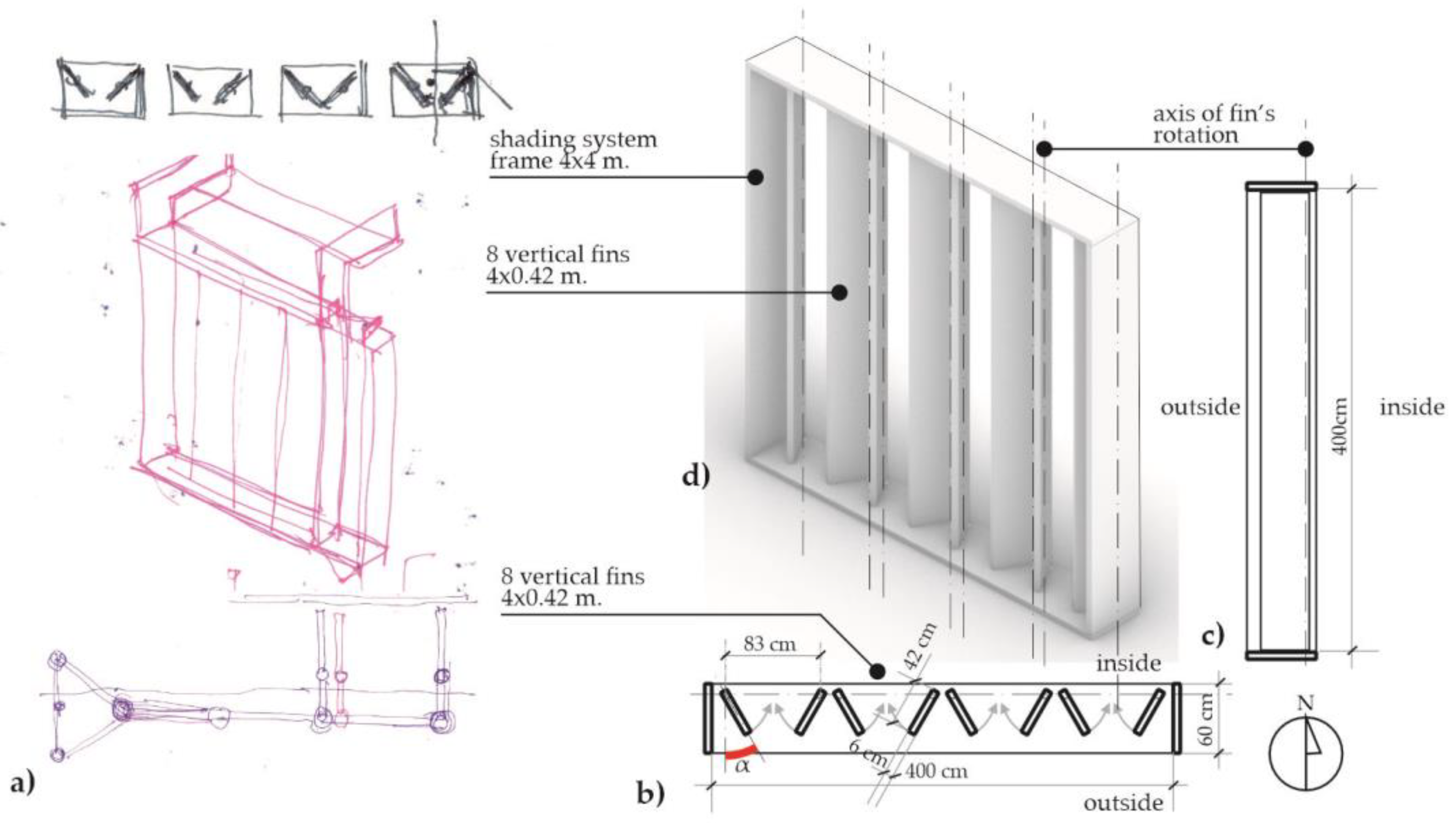
The author developed the concept of the shading system with vertical fins based upon the request of an undisclosed client. The shading system was developed for the fully glazed facade section of 4 × 4 m in the front view with the south orientation in Wrocław, Poland, at 51° lat. N. The shading system was screening a deep office room of 4 × 8 m in plan. The shading system was conceptualized using architectural sketches, analysis of the artistic and architectural form, computer models, and finally, the reduced-scale prototype 1:20.
3.1. Kinetic Facade Proposal
After the initial stage of development, the planned shading system consisted of eight vertical fins, each 42 cm wide, side-hung, and rotating inwards in four groups of two. They work on a plane in a similar way to double doors. Figure 2 shows the various stages of the concept development, with the final system geometry.
The inspiration for the kinetic facade came from observing and analyzing traditional exterior shutters, with two fins (also called wings) that rotate by the side-hung hinges. The central concept was that the fins create a system of vertical shades perpendicular to the glazing. Even without the kinetic behavior, the system of vertical fins has an advantage over the unprotected fully glazed facade. Alzoubi and Al-Zoubi claim that “vertical shading devices can simultaneously provide good daylighting and minimum heat gain in spaces” [8].
The author chose vertical fins for the kinetic facade system for two reasons: (i) to avoid snow accumulation, which was a significant concern due to the local climate and (ii) to provide a view outside for the workers in the room, even with the large angle of the fin’s vertical rotation. The author knows about the research findings indicating vertical fins’ lower effectiveness for south-facing facades [8]. However, snow could pose an additional load and blockage threat to the shading system. Climate change and the rise in average temperatures have affected Wrocław, too. Still, this change has had a limited impact on the snow cover, which has varied considerably since 2000, with some seasons (e.g., 2009/2010) having an average snow depth of 9.8 cm and snow lasting for 107 days [40].
3.2. The Current Empirical Research
This paper proposes a new method to evaluate the daylight performance of the suggested shading system using the (i) simulation of UDI and DGP on the Radiance-calculated illumination values at the work plane in the test room and, (ii) experimentally using the reduced scale prototype installed in the testbed.
The method is innovative because it considers some novel factors, such as the following:
- A computer model of the facade that was prepared and tested in different scenarios by determining the annual illuminance on the work plane, 0.85 m above the floor level. The method uses the simulation performed by the Radiance engine. In addition, the method includes different kinetic scenarios for the vertical fins that rotate (close and open) according to the illuminance level at the work plane in the office room. UDI was used successfully in a previous paper to measure the daylight level [41];
- A computer-aided method that uses real weather data in the EPW file (Energy Plus Weather file) that reflects the actual climate and daylighting conditions measured at the airport of the city of Wrocław (51° lat. N);
- A shading system prototype that was conceptualized, designed, built as a reduced-scale mock-up, and tested experimentally in real weather conditions;
- The results of the measurements, which showed interesting insights that were impossible to detect in the simulation studies.
The main goal of the research was to improve visual comfort (by increasing UDI and decreasing DGP) by optimizing the shading system fins’ rotation angle and potential kinetic scenarios, which shows its innovativeness.
3.3. Method
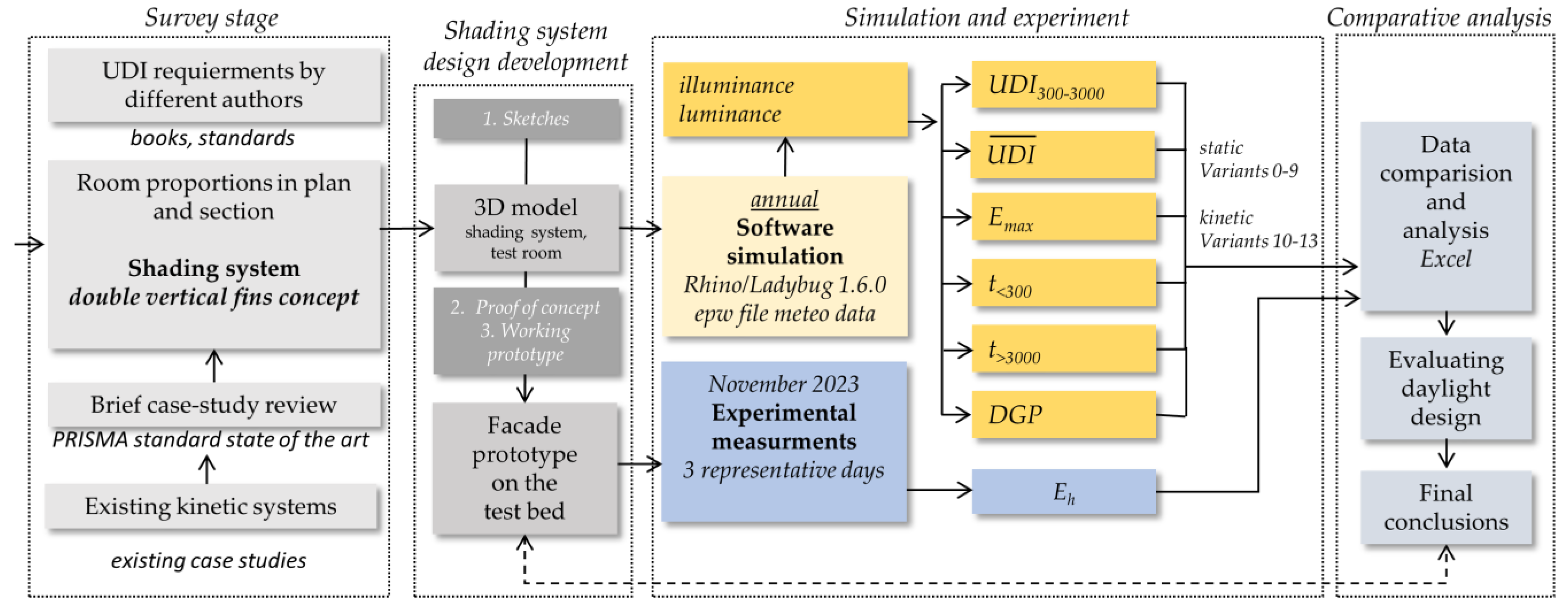
The author conducted two types of analysis of the proposed shading system: (i) first stage—an annual UDI300–3000 and glare simulation, using standardized weather data for the given location obtained from EnergyPlus’s database, using different geometry of the shading system in different scenarios (variants); (ii) second stage—an experimental measurement of illuminance on selected clear days in November 2023, using a south-oriented, reduced-scale prototype of the facade installed on the testbed specifically constructed for measuring daylight. Figure 3 presents the schematic diagram of the methodology, and the author gives a detailed explanation in the respective chapters.
4. Simulation
In the first research stage, the author performed a computer simulation of the proposed shading system in different scenarios described and compared below.
4.1. Simulation Method
The author used the software Rhino, ver. 7, to model the virtual office room and the proposed shading system. Daylight was simulated using the Ladybug/Honeybee 1.6.0 plugin with the Radiance daylight simulation engine. This tool has been validated by many previous studies, such as Reinhart and Walkenhorst [42], Ng et al. [43], and Yoon et al. [44]. Kharvari confirmed the accuracy of the Honeybee/Ladybug plugin for Rhino in a 2020 publication in the journal Solar Energy by performing an experimental validation of the Radiance computational engine embedded in Ladybug using “grid analyses under an overcast sky with a certain illuminance level” [45]. Kharvari found that the average difference in illuminance levels calculated vs. measured for all points was 9%, while the difference in the average illuminance level of the room was 2%. Those results show that Radiance accurately estimates the overall illuminance level on the analysis grid. Kharvari concludes, “[…] Radiance is still the most powerful and accurate tool for predicting illuminance levels in buildings.” [45]. In addition, Reinhart and Andersen showed that translucent materials “can be modeled in Radiance with an even higher accuracy than was demonstrated earlier […]” [46].
For the simulation of kinetic variants, the so-called phase method was used, in which a set of daylight metrics is calculated for a discrete number of shading device settings. The algorithm picks the illuminance value of the predicted shading system state for every hour of the simulated schedule, depending on the predefined triggering factor (e.g., internal illuminance level, irradiance level, etc.). Ch. Reinhart suggested this method in the “Daylighting Handbook II” [47]. A similar approach was suggested by Do and Chan in 2018 [48].
4.2. Simulation Setup for UDI and DGP
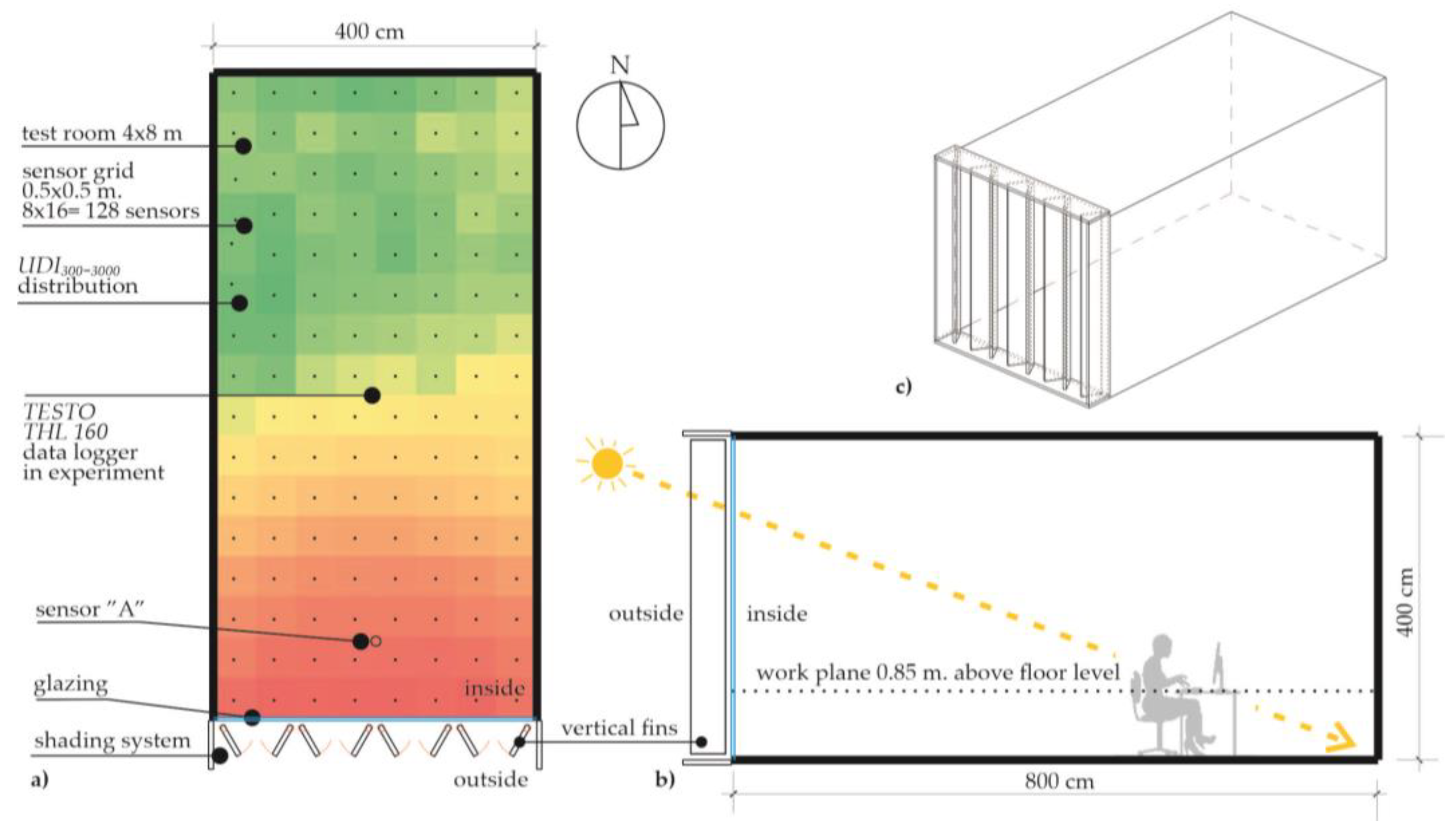
The test room was an office with a 4 × 8 m floor plan and a 4 m height (undisclosed client’s requirement). Table 2 lists the reflectance and transmittance parameters of the surfaces. The room had one daylight source: the side with a full-height facade protected by the proposed shading system, which Chapter 3 describes in detail. The test room’s longer axis of symmetry aligned with the compass directions (N–S). All the materials used for the simulation had the parameters given in Table 2, according to the geometry given in Figure 2.
4.3. Analysis Assumptions for Simulations of Daylight
The author calculated the values of horizontal work plane illuminance Eh using 128 virtual sensors (grid of 8 × 12 measuring points, approx. four sensors per m2) on a square grid of approximately 0.5 × 0.5 m at the level of the work plane in an office room (the height above the floor level 0.85 m), as shown in Figure 4. At the same time, a single virtual sensor marked “A” was placed in the front of the room, 1 m from the facade, and recorded horizontal illuminance values (lux). Sensor “A” was placed in the middle of the room to detect over-illumination near the facade. This sensor triggered the state change in the kinetic system and provided performance metrics—t > 3000, t < 300—used to benchmark simulated variants.
UDI300–3000, DGP, and other metrics were calculated using the real weather data from the Institute of Meteorology and Water Management, National Research Institute, for Wrocław, a city in south-west Poland (51°06′ lat. N, 17°01′ long. E). The data were obtained as a *.epw file containing the irradiance data for creating sky matrices in Radiance.
4.4. Brief Description of Performance Indicators
Two leading indicators evaluate the performance of the proposed shading system: (i) quantitative—illuminance calculated for working hours Eh (8:00–17:00, five days a week, 2340 h per year for 12 static and kinetic variants), and (ii) qualitative—DGP.
Based on the values of illuminance Eh, the following annual metrics have been taken into account in the evaluation of visual comfort. A brief description of the main metrics is given below.
4.4.1. UDI300–3000 and
Useful daylight illuminance was defined for the first time in the paper by Nabil and Mardaljevic [49] in 2005 as a metric which “determinates the percentage of the time that the interior daylight illuminance in a room falls within a user-defined range”. This metric is specifically pointed out to be the most appropriate for estimating daylight comfort based on the evaluation of daylight metrics provided by Boubekri and Lee [50]. Mardaljevic et al. stated that “range 300 to around 3000 lux is often perceived either as desirable or at least tolerable” [51]. Considering all other requirements (e.g., EN 17037, 2018 [9]), it could be generalized that the greater the value of UDI300–3000 the better, because this means a longer time in which the requirements are met.
Moreover, the author introduces an additional metric, which is the mean of the final UDI300–3000 values, and denotes it as . This metric might be seen as a simplification that does not show the whole spatial distribution of the illuminance results. Still, it makes it easier to present the results of the following variants with a single number.
4.4.2. Uniformity of UDI
Originally, uniformity of illuminance was calculated as a momentary metric, describing the distribution of daylight in the room based on momentary values of illuminance, and was defined as “the ratio between the minimum illuminance (from daylight) on the working plane within a room and the average illuminance (from daylight) on the same working plane” [52]. The instantaneous value of uniformity describes the distribution of daylight in a room well enough that it can also be used to describe uniformity annually. Instead of instantaneous values to describe uniformity annually, the author used UDI300–3000 values calculated for the working plane in the room. The uniformity of UDI is denoted as UUDI and calculated using the Formula (1):
where UDImin is the minimal value of UDI300–3000, and is an average value of UDI300–3000 at the surface of the working plane, calculated for 128 sensors. As the author stated a the previous paper, “if uniformity equals 1, the working plane is evenly illuminated, the lower the value of UUDI (as the fraction of unity), the lower the uniformity of illumination” [53].
4.4.3. Daylight Glare Probability
Briefly, daylight glare probability is the qualitative metric describing the user’s reception of glare, which is defined as “condition of vision in which there is discomfort or a reduction in the ability to see details or objects, caused by an unsuitable distribution or range of luminance” (CIBSE Lighting Guide LG7, 2015) [54]. DGP was defined for the first time in 2006 in a paper published by Jens Christoffersen [55]. This metric is calculated according to Formula (2), where Ev is the vertical eye illuminance [lux]; Ls is the luminance of source [cd*m−2]; ωs the solid angle of source; and P is the position index (see ref. [55]).
According to Wienold and Christoffersen, with DGP above 35% (<2000 lux), the glare is rated as “Perceptible”, while with DGP above 45% (>6000 lux/>4500 lux), the glare is “Intolerable”.
Different glare discomfort thresholds were reviewed by Suk in 2019 [56], based on various studies by different authors: Sutter et al. > 3200 lx [57], Linney > 2740 lx [58], Wymelenberg and Inanici >4000 lx [59]. Mardaljevic et al. [51] set the 3000 lx threshold as a sign of discomfort glare, meaning that the glare probability (DGP) increases when the illuminance goes beyond 3000 lux. The author of the presented paper uses this maximum threshold level. Some authors argue for different illuminance levels, such as 2500 lux or even lower. Certificate LEED v4 introduces the Annual Sunlight Exposure (ASE) metric. ASE threshold is the percentage of the floor area that receives more than 1000 lux for over 250 out of 3650 annual hours. The requirement is met when no more than 10% of the floor is affected [60]. It should be clearly stated that LEED standards are voluntary in Poland.
In the presented paper, taking into account the crucial issue of low-altitude angles, DGP is simulated for the following dates and times:
- 22 September, autumnal equinox, at 14:00 solar time.
- 9 November (to align with the experimental data) at 14:00 solar time.
- 21 December, the winter solstice, at 14:00 solar time.
4.4.4. Other Metrics
Other used metrics were based on the values of annual values of illuminance and UDI:
- The number of hours in the simulated year for which the illuminance exceeded 3000 lux at the sensor “A”—t > 3000,
- The number of hours in the simulated year for which the illuminance was lower than 300 lux at the sensor “A”—t < 300,
- Median illuminance in the year MdnEh at the sensor “A”,
- Maximal value of UDI300–3000 denoted further as UDImax,
- Standard deviation σ for final UDI300–3000 distribution,
- Factor A—the percentage of the work plane with UDI300–3000, which is over 50%.
4.5. Sequence of Simulation
The author has performed the simulations according to the following sequence. After each step of the simulation, the interim comments were formulated, and conclusions were drawn, feeding the next steps of the simulation:
- Static
- ○
- Variant 0—no shading system installed,
- ○
- Variant 1–9—fixed vertical shading fin gradually rotated towards the facade’s surface (from 0 to 80°).
- Kinetic
- ○
- Variant 10—fins rotate 40° when sensor “A” exceeds 3000 lux,
- ○
- Variant 11—fins rotate 50° when sensor “A” exceeds 3000 lux,
- ○
- Variant 12—fins fixed at 40° and rotate 10° when sensor “A” exceeds 3000 lux,
- ○
- Variant 13—modified facade design, lower fins rotate 50° when sensor “A” exceeds 3000 lux.
4.6. Simulation Results
According to the methodology described above, the author conducted a series of annual UDI300–3000 simulations for static vertical fins. Performance indicators are shown in Table 3. The complete set of UDI300–3000 values for the analyzed static variants is provided in Supplementary Materials.
4.6.1. Static Variants
The first simulated scenario was static Variant 0, where no shading system is installed, and a fully glazed facade is exposed to the south. This variant was simulated as a baseline scenario for comparing the results with other variants. Simulation results in Variant 0 show over-illumination in the 3–4 m zone from the facade. Near the glazing, the values of UDI300–3000 drop below 12%, and the UUDI equals 0.25. See Table 3, column 2.
Next, static variants from 1 to 9 were simulated, with the fixed vertical fins rotating towards the surface of the facade’s glazing in 10°- increments for each following variant. Variant 1 (0°—shading system constantly open) also shows over-illumination near the glazing, with the values UDI300–3000 dropping below 20%. However, it has to be observed that the over-illumination zone is approx. 3 m deep, while the remaining part of the room is adequately lit. The values of UDI300–3000 near the facade are 2.5 times higher than in Variant 0. In general, it might be concluded that Variant 1 shows an improvement compared to Variant 0 in the context of the values of UDI300–3000 and uniformity, especially in the room’s depth. Those results confirm the findings of Alzoubi and Al-Zoubi [8].
The overview of the results of the simulation of variants from 2 to 9 shows that in the first five variants form 1–5 (10 to 40° of α, incremental fin rotation angle), the values of are in the range of 57.99 to 70.67%, which shows relatively good quantitative daylight comfort. At least 63% of the room surface in those variants is characterized by UDI300–3000 >50%, which means that almost the entire room fulfils the requirements of EN 17037/2018 (half of the surface of the room receives the proper amount of daylight for at least 50% of the time). The values of UUDI range from 0.33 for Variant 1 to 0.73 for Variant 5. Values of and UUDI are gradually declining for Variants 6–9. In the last Variant 9, only 2% of the room surface is adequately lit, and uniformity is very low UUDI = 0.00. The reason for this is that the minimum UDImin value for Variants 8 and 9 is 0, which also implies a uniformity of 0. Those values are expected, as the shading system is almost completely closed, allowing daylight only at the very proximity of the facade.
The simulation of static Variants 1–9 allowed for the specification of the optimal fixed vertical fin rotation angle α, which could be determined as 40° For Variant 5, the analyzed daylight performance metrics achieved the highest values of = 73.61% and UUDI, which equals 0.67. In addition, this finding could be enforced with the determination of standard deviation, which has the lowest value σ = 7.08, which confirms the high uniformity of spatial daylight distribution in the room. In addition, Variant 5 provides almost 99% of the room floor area with a UDI300–3000 greater than 50%. The highest standard deviation of σ = 23.75 was simulated for Variant 0 (no shading system), which is characterized by a very low UUDI uniformity of 0.25.
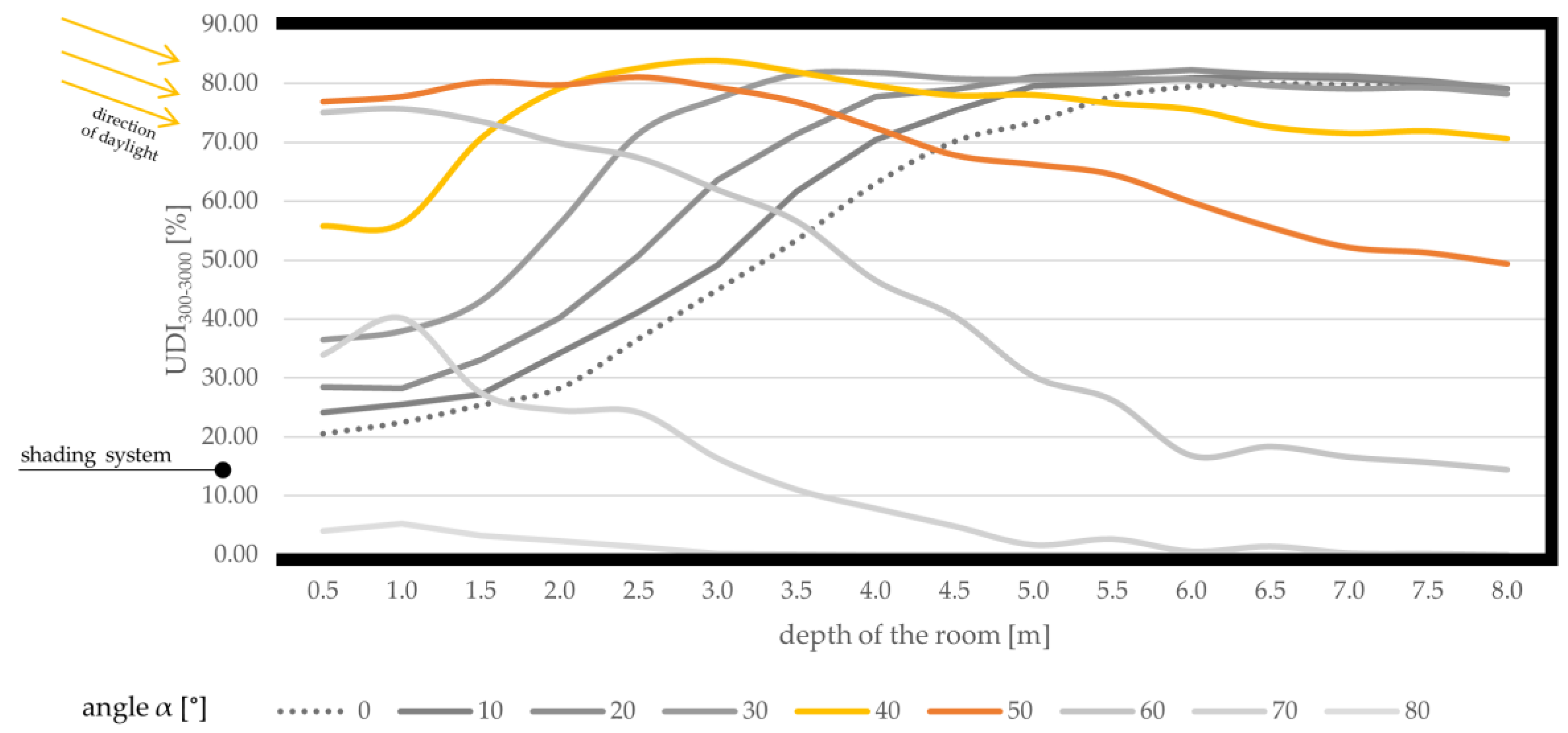
For better visualization of the simulation of UDI300–3000, a diagram—see Figure 5—was prepared to show the distribution of UDI300–3000 values in the longitudinal section of the test room (8 m depth of the room in cross-section; the fully glazed facade is located at the left side). The graph’s continuous yellow line shows spatial UDI300–3000 distribution in the longitudinal section of the room for Variant 5, compared with the other variants.
The above-given data informs the following analysis:
- In the facade’s proximity, the highest values UDI300–3000 are achieved for Variant 6 (α = 50° orange line in Figure 5). In the frontal zone of the room, to a depth of approx. 3–3.5 m, the values of UDI300–3000 are between 77% and 81%. Further from the facade, the values drop to 50% at 6.5 m, which is still acceptable.
- In the back of the room, the highest values UDI300–3000 are achieved for Variants 1–4 (Variant 0 was not included in this analysis because the shading system has to be installed anyway). In those Variants, the room’s depth is characterized by the values of UDI300–3000 of approximately 79–80%.
DGP analysis shows that the values decrease progressively as the fins gradually close. The glare is imperceptible when the α angle is 40° or more (DGP < 35%). It can be observed that as the fins open gradually, glare increases, especially when the sun is low. In extreme cases, in Variants 0–3 on the day of the Winter solstice, the DGP reaches a value of 100%, which means the observer faces direct sunlight.
After analyzing the UDI300–3000 values in a longitudinal section of the room, it was hypothesized that a dynamic system that adjusts the fins’ angle based on internal illuminance might be more efficient than a static system. The author analyzed the static fins and experimented to verify this hypothesis.
4.6.2. Altitude Study
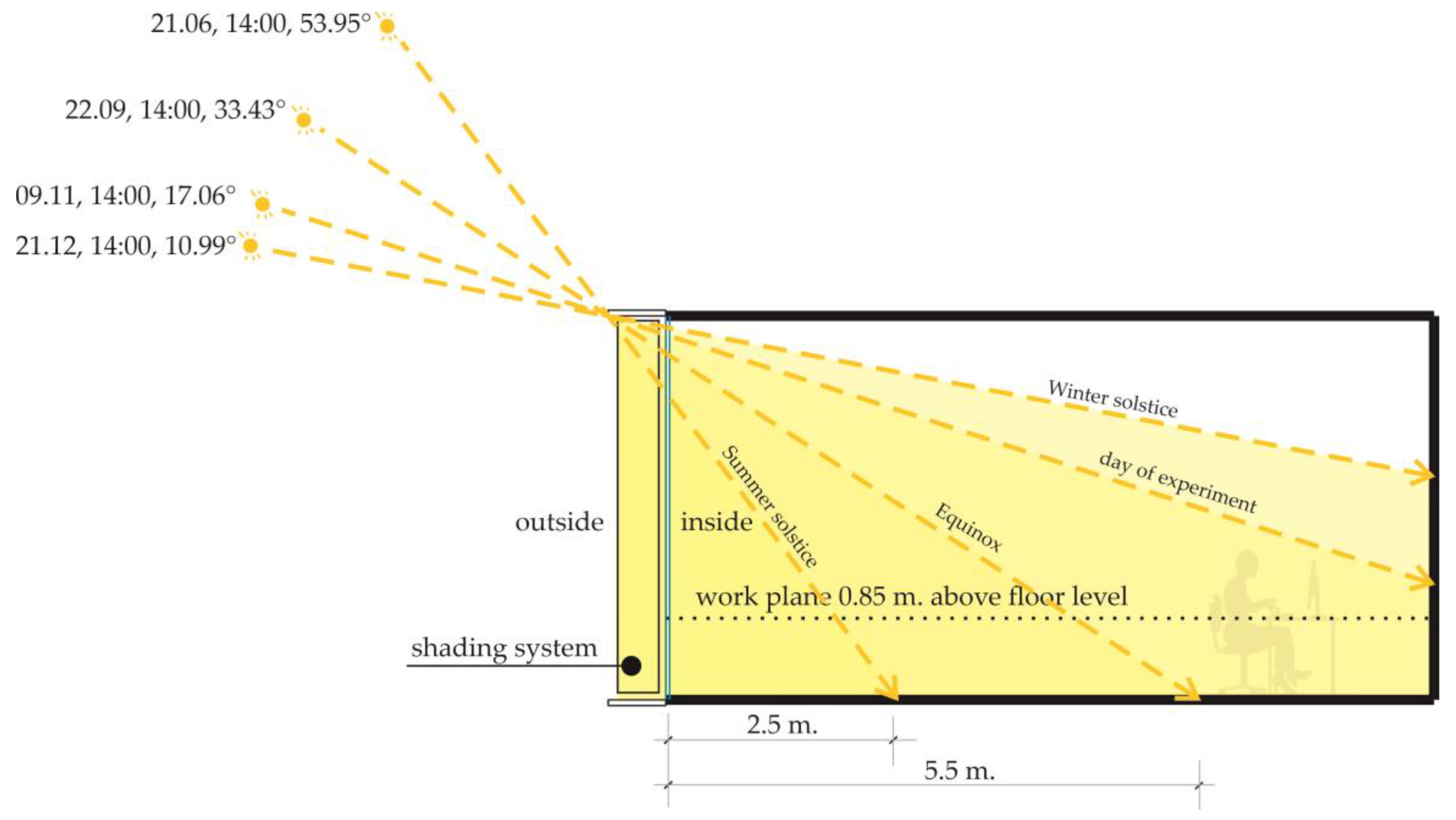
The author plotted an altitude study to show the sun’s penetration depth in the room at low angles of incidence. The study was done at 14:00 solar time. On the summer solstice, the sun reaches about 2.5 m. deep; on the equinox, it reaches 5.5 m. deep; on the 9 November and the winter solstice, the sun’s rays reach the wall at the back of the room. The dates and solar altitude angles are given in Table 4 and Figure 6.
The author calculated the values of DGP for the average sitting person (1.2 m eye height) inside the room, looking south towards the sun at 14:00 solar time. The dates chosen to calculate DGP are based on the relatively low sun altitude and potentially higher glare probability. DGP and momentary luminance values (luminance evaluation) for the kinetic variants are presented on false color diagrams from the user’s perspective, with the maximum value of 4000 cd*m−2 in Table 5 below.
4.6.3. Kinetic Variants
Kinetic Variants are simulated using the simulation results of static ones, using the phase method proposed by Ch. Reinhard in the book Daylighting Handbook II [47]. The triggering factor for the change of the state of the shading system is the level of illuminance detected by sensor “A”, which is placed inside the room, in the middle, at a distance of 1 m from the surface of the facade (please refer to the chapter “Simulation setup for UDI and DGP”). When the illuminance level surpasses 3000 lux, vertical shading fins are rotated towards the surface of the fully glazed facade, decreasing the amount of daylight entering the test room. The fins are rotated back into the original position when the illuminance level decreases. Three kinetic scenarios have been tested. When the illuminance level surpasses 3000 lux at sensor “A”,
- (i) Fins rotate towards the facade at the angle of α = 40° (the optimal variant for static fins),
- (ii) Fins rotate towards the facade at the angle of α = 50° (the next most optimal variant for static fins),
- (iii) Fins are constantly closed at 40° (like in static Variant 5) and rotate towards the facade at the angle of α = 50°.
For the clarity of the spatial distribution of UDI300–3000, the simulation results of kinetic Variants 10–13 are presented on room plans compared to the results of static Variant 5 (see Table 5). The fully glazed facade is at the bottom, and arrows indicate the direction of daylight. This comparison evaluates the performance of the kinetic variants relative to the static Variant 5, which was identified as the optimal solution in the static case.
Variant 10, with the fins open for 1161 h a year (1161 is the number of hours when the sensor “A” exceeds 3000 lux), has higher UDI300–3000 values than Variant 5 in the back of the room but lower ones near the glass facade. The average UDI300–3000 values are slightly higher, but the uniformity is lower. Variant 11 performs better than Variant 5 and Variant 10. It has a 60% higher uniformity of 0.81 and the lowest standard deviation of 5.56. Variant 12 improves the daylighting in the front of the room but worsens it in the rear zone. This phenomenon is because the fins are not perpendicular to the facade but remain fixed at 40° in the “open” position. Values of are similar in all the compared variants; the difference is only ±5%.
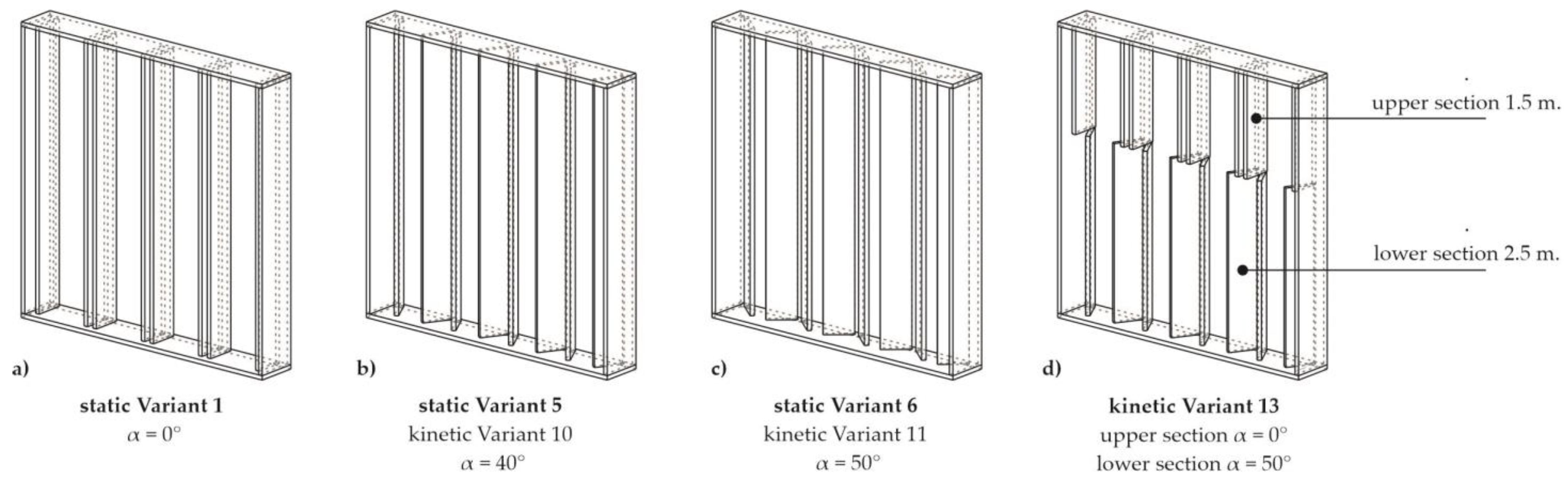
Spatial UDI300–3000 distribution in Variant 12 and the altitude study informs the following conclusions. The kinetic system efficiently lowers the illuminance in the front part of the room to a depth of approximately 4 m, simultaneously worsening daylight availability in the room’s depth. To improve the shading system, Variant 13 divides the system into two sections, as shown in Figure 7d. The lower section of 2.5 m height, and the upper section of 1.5 m height, are proposed to be operated separately according to the following scenario: when the level of illuminance in the front of the room surpasses 3000 lux detected by the sensor “A”, the lower shading fins are rotated at the angle of 50°, while the upper ones remain open, allowing the light into the depth of the room. When another threshold of 3000 lux is exceeded at the sensor “A”, the upper section of 1.5 m is closed, limiting the daylight entering the room.
The results in Table 5 show that Variant 13 has higher UDI300–3000 levels in the back of the room than Variant 12. The UDI300–3000 values in the back are almost 11% higher (61% vs. 68%) in Variant 13. In addition, Variant 13 has the highest UDImax value of 85.81% and the highest UUDI uniformity of 0.86 among all the static and kinetic variants.
The analysis shows that the kinetic scenarios improve the daylighting performance compared to the static variants. Variant 13 is the best-performing kinetic scenario, with a 33% increase in values over Variant 1. Additionally, the illuminance simulation results show improvement in all the other daylight metrics. In Variants 11, 12, and 13, 100% of the room area has UDI300–3000 values above 50%, whereas in Variant 13, almost 40% of the room area has UDI300–3000 values above 80%. Moreover, UUDI uniformity is very high, at 0.86.
5. Experiment
Kinetic shading systems are not commonly designed or used in practice. Globa et al. review the latest kinetic facade projects, with eleven case studies of seven systems built and tested in the field [26]. Among the different types of movement (rotation, folding, vertical linear movement, and actuation), the author chose to use rotating facade fins based on the simulation results presented in the previous chapter.
5.1. Prototype Development
After completing the simulation, the author built a reduced-scale shading system prototype using the following steps:
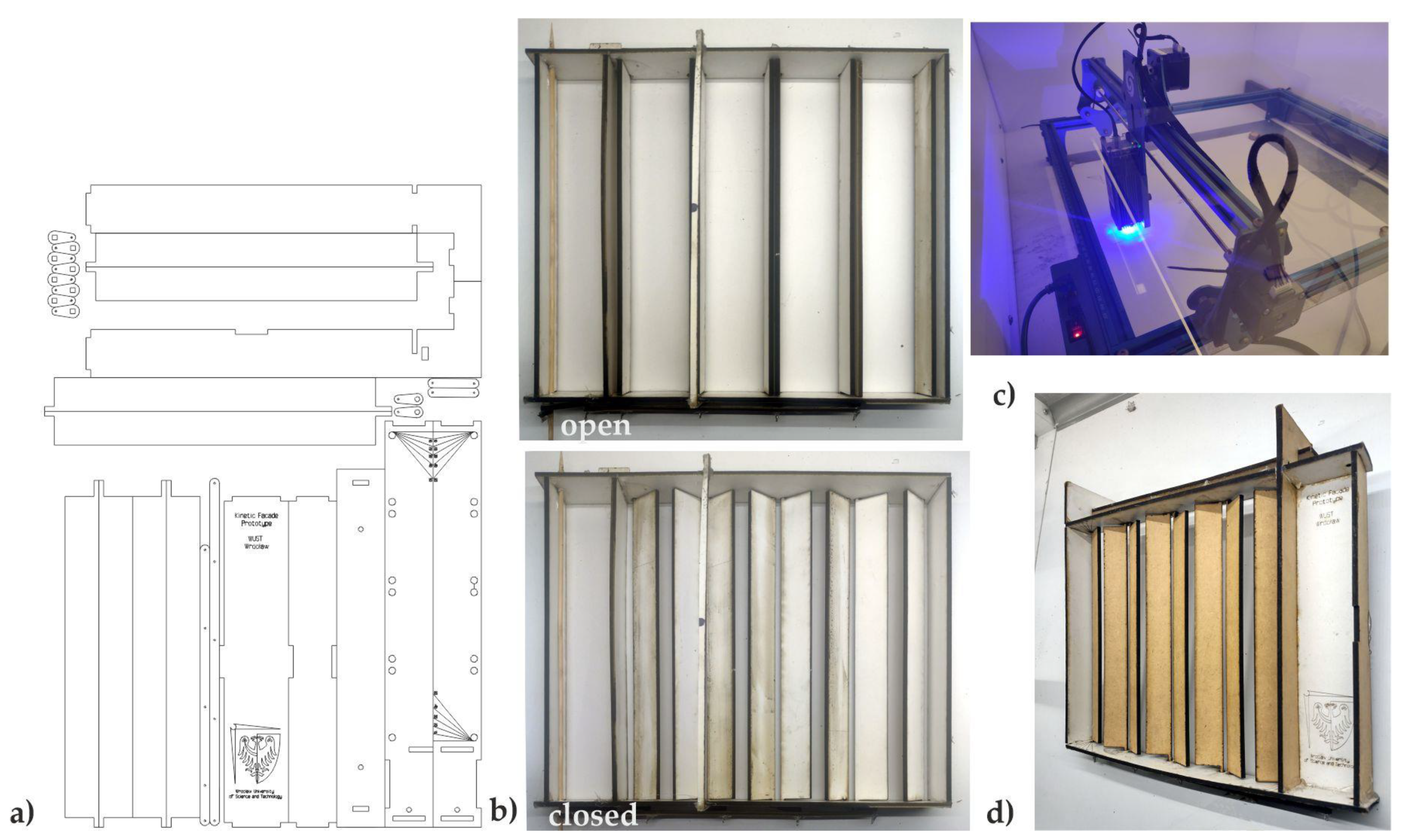
- Proof-of-concept: A CAD software, Rhino ver. 7, was used to design and visualize the geometry of the shading system components. A laser cutter was used to make the first prototype out of 3 mm-thick foamed PVC. The first trials showed that a kinetic shading system could operate mechanically (the fins rotated in groups). Initial indoor tests were performed.
- Prototype: The author improved the prototype design based on the lessons learned from the previous stage, such as insufficient frame rigidity. The outer frame of the prototype was designed to fit the existing daylight measuring testbed. The author used rapid prototyping methods to make a weatherproof 3 mm particle board prototype; a laser cutter was used to cut the parts. Then, the shading system was assembled with steel joints and glue. This prototype showed the basic functionality of the shading system and was considered a “low-fidelity” one, but it worked well in the testing stage. See Figure 8 for the prototype.
- Testing: The author installed the prototype on the testbed at the end of October 2023. The prototype was tested for a week in early November 2023 under clear-sky conditions.
5.2. Experiment Method
The experiment aimed to (i) test the hypothesis that a kinetic facade could improve the visual comfort in a room, using a particular month with low altitude solar angles as an example, and (ii) monitor how the shading system worked in actual weather conditions, identifying any issues that the simulation could not predict.
5.2.1. Experiment Location, Climate Conditions
The experimental investigations were performed at the beginning of November 2023 at Wrocław University of Science and Technology, Poland. Wrocław is a city located in Poland, at 51°06′36″ N 17°01′20″ E, elevation approx. 120 m above sea level. According to the Köppen climate classification, Wrocław has an oceanic climate (Cfb), bordering on a humid continental climate (Dfb) using the 0 °C isotherm. The city’s climate is characterized by moderate and arid winters with frequent cloud cover and warm and mostly sunny summers with high rainfall, often associated with thunderstorms. Climate change, which has resulted in a significant increase of 56% in the average sunny hours in Wrocław, from 3.2 h/day in 2000 to 5 h/day in October–December 2022, was the primary rationale for testing the prototype in low solar altitude conditions [40]. Detailed climate conditions are presented in Table 6.
5.2.2. Testbed
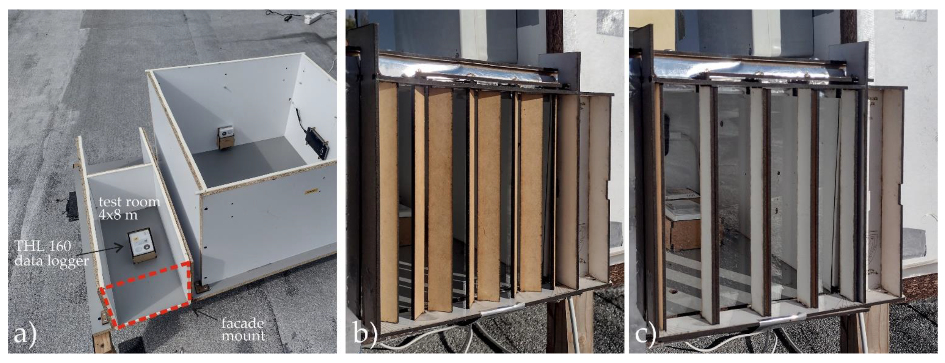
The author built a reduced-scale model of the test room with a weather-resistant particle board. The test room model was exposed to real weather conditions with the glazing facing south. The materials had the same parameters as the virtual test room in the simulation. The author used color charts to find the reflectance values of the elements in the testbed and match the values in the virtual model. The author used an actuator to control the shading system based on the sun’s position. The primary goal was to avoid direct sunlight in the room. The author programmed the fins to close at 9:45 and open at 13:30 (approximately). Figure 9 shows the experiment, with photos of the prototype in the “open” and “closed” positions on the testbed.
5.2.3. Experimental Equipment
Three illuminance sensors (data logger Testo THL 160, recording level of illuminance every 15 min) were installed inside the setup to monitor illuminance level Eh (horizontal work plane illuminance). One was centrally located, and two were in the room’s depth in corners. Additionally, a cell phone (Samsung Galaxy J5) with Framelapse ver. 10.4 software was installed inside the mock-up to record the frame lapse movies, showing the lines of shadow and the dynamics of the sun’s path (camera capture movies are available as Supplementary Materials). Simultaneously, the irradiance data Id and It were collected at the Meteorological Observatory of the Department of Climatology and Atmosphere Protection, Wrocław University (51°06′19.0″ N, 17°05′20.0″ E, elevation: 116.3 m) using pyranometer Kipp and Zonen CM 11. It must be noted that the distance between the testbed and the local weather station is 9 km; therefore, the cloud coverage dynamic is not always precisely replicated. The irradiance data were used to determine clear days and construct sky matrices. The details of the experimental equipment are given in Table 7.
5.2.4. Duration of the Experiment and Schedule
The measurement campaign took a week from the 2nd to the 9 November 2023. The author limited the analysis of experimental data to clear days only, as the author reasonably assumed that a kinetic facade would be used only on those days. The irradiance values It were compared with GHI (global horizontal irradiance) values derived from the Adnot–Bourges–Campana–Gicquel model [62], calculated respectively for a given time and location. A day is considered clear if the measured values are within ±10% of the GHI for more than half of the daylight hours. According to this criterion, the 4, 7, and 9 November 2023 were clear days, with maximal values of global irradiance It around 300 W × m−2. These days were selected for further analysis because a complete measurement data set was available. For the remaining cloudy days, the facade remained deliberately open or closed for an entire day.
5.3. Experiment Results
Results of the measurements of illuminance Eh exp in the selected days are presented in Table 8. The graph illustrates the measured illuminance Eh exp (continuous yellow line) for a centrally located data logger, simulated illuminance Eh sym (dashed brown line) for a centrally located virtual sensor, and global solar irradiance It (dotted yellow) just for the purpose of comparison.
Simulated illuminance values of Eh sym were obtained using real global It and diffuse Id irradiance values. Those real-weather values were used to construct sky matrices, and subsequently, the values of Eh sym were calculated (the “Point in Time” Honeybee component was used). The author followed the same procedure as in the annual UDI300–3000 simulation, using the same virtual model and settings as in Table 2.
The graph shows the moments of intervention (when the kinetic shading system closed and opened) with black and blue dots. The author did not intend to validate the simulation, but the simulated values Eh sym were similar to those measured; at least, the correct trend was visible. When the shading system was closed, the maximum midday values of Eh exp were around 3000 lux for the central sensor. The measurement and the simulation showed a significant temporary increase in illuminance (up to 15–18 Klux) caused by the low-altitude solar rays directly hitting the virtual sensor or the data logger through the gaps between the vertical fins. Moreover, this phenomenon created high contrast. The peaks in the simulation and the experiment did not coincide. The author hypothesized this was because the simulation used one-hour intervals while the testbed measurements used 15-min intervals. In addition, multiple peaks were measured on the 7th and 9th of November 2023. In addition, the author speculated that the different cloud cover might have caused variations between the experiment days.
The shading system performed optimally on the 4th of November 2023. The graph indicated a steep decline in illuminance when the fins closed (black dot). The subsequent two days also exhibited lower Eh exp values, but the reduction was less noticeable. The illuminance rose when the fins reopened (blue dot).
The experiment confirmed that the closed kinetic system reduced the internal illuminance levels (Eh exp). However, it also revealed that the fins could not effectively block all the direct sunlight due to the low solar altitude. The low incident angle led to peaks in illuminance measured by the data logger.
6. Discussion
The shading system performed well in quantitative metrics. The simulation sequence helped the author find the optimal static angle of α = 40° for the vertical fins. Moreover, the kinetic scenarios improved the quantitative metrics, especially Variant 13, which had UDI300–3000 values over 80% for almost 40% of the room area and UUDI uniformity of 0.86. These results met the requirements of many standards, such as EN 17037, which states that “minimum daylighting provision of 300 lx of natural light illuminance over 50% of the space and 100 lx minimum over 95% of the space, both for more than half of the daylight hours in the year” [9] are required.
The low solar altitudes and low α angles adversely affected the qualitative metrics. All the static variants with angles below 40° had disturbing or intolerable glare, with some very high values of 100% for Variants 0–3 at the winter solstice. The measurements carried out in early November 2023 confirmed the poor performance of the proposed system under low solar altitudes. The measurements showed that the direct sunlight caused high illuminance values of 15–18 Klux at the work plane level, even when the fins were closed. The peak illuminance values were three times higher than the average levels for those days. Other researchers have also noticed this phenomenon in a different location [33].
7. Conclusions
This paper presents a two-step methodology for analyzing and evaluating a kinetic shading system. The process consists of simulation and measurement phases. The main findings of this study are:
- The optimal fixed angle α of the vertical fin for the shading system was 40° according to the UDI300–3000 metric. In addition, the quantitative annual daylight analysis revealed that increasing angle α reduced over-illumination near the glazed facade but increased under-illumination in the back of the room.
- The kinetic scenarios with an improved shading system geometry (Variant 13) enhanced visual comfort by approximately 33% compared to the open-system geometry (Variant 1).
- The qualitative momentary metric DGP suggested that the shading system only mitigated glare effectively for angle α when larger than 40° (DGP < 35%). This result was attributed to the low solar altitude during the simulation and the experiment.
The discussion could be concluded with the following insights. The shading system performed well in terms of quantitative daylight metrics but not in terms of qualitative ones. A supplementary device, such as a roller shade or electrochromic glazing, might be required to prevent glare from direct sunlight during low solar altitude periods. The study demonstrated the difficulties of using vertical kinetic shading systems in seasons with low solar altitudes. The paper suggests some possible directions for future research in Section 7.2.
This study contributes to the field of shading systems in the following ways:
- Developing a shading system from the concept stage to the tested prototype stage, using ideation, proof-of-concept, digital fabrication, and prototype testing methods;
- Applying a two-stage methodology for evaluating and assessing the shading system based on computer simulations and experiments;
- Identifying phenomena that were not captured by the simulation due to its temporal resolution limitations through prototype testing in an experiment;
- Providing insights on the visual comfort performance of the shading system.
7.1. Limitations of the Study
This study has some explicit limitations that should be acknowledged. First, the analysis was limited by the high computing power required, and only 15 variants were tested. Second, some phenomena were not detected by the simulation, and more comprehensive measurements are necessary to account for the real weather conditions. The *.epw files used for the simulation might also need to be updated due to climate change (e.g., more sunny days). Third, the vertical fins were angled relative to the fully glazed facade (40° and 50° in static and kinetic variants), which may have compromised the horizontal view angle (14° to 28°) required by the European Standard EN17037, especially for the workplaces in the back of the room. Fourth, the shading system was designed vertically to resist snow, but other natural forces, such as wind, might threaten its integrity.
7.2. Future Research
The proposed shading system could be further improved by adding a glare control device to mitigate the work plane’s high illuminance peaks and contrast. Another possible improvement is a different geometry of the shading system that is resistant to snow accumulation. Devices that block direct light at eye level while allowing daylight to enter the room are needed for low-altitude solar angles. Combined solutions with fins at different heights are another option to explore. This article does not compare the cost-effectiveness of the static and kinetic variants of the shading system. Future research could examine the shading system’s cost and finance aspects. Moreover, emerging technologies, such as innovative materials, sensors, and controls, could enhance the adaptability and responsiveness of daylighting systems to changing conditions and user preferences. These technologies are another topic for future research.
Supplementary Materials
The following supporting information can be downloaded at: https://drive.google.com/drive/folders/1tWo4N3kPvx_BoBuL_p2bYGau4r3LZ8lc?usp=sharing (accessed on 15 January 2024).
Funding
This research received no external funding. The APC was funded by the Wrocław University of Science and Technology.
Institutional Review Board Statement
Not applicable.
Informed Consent Statement
Not applicable.
Data Availability Statement
The raw data supporting the conclusions of this article will be made available by the author on request.
Conflicts of Interest
The author declares no conflicts of interest.
Nomenclature
| Ev | vertical eye illuminance [lux] |
| Eh | horizontal work plane illuminance [lux] |
| Eh sym | simulated horizontal work plane illuminance [lux] |
| Eh exp | measured horizontal work plane illuminance [lux] |
| UDI300–3000 | useful daylight illuminance in the rage of 300–3000 lux [%] |
| mean of the final UDI300–3000 values | |
| UDImax | maximal value of UDI300–3000 [%] |
| UUDI | uniformity of final UDI300–3000 values |
| DGP | daylight glare probability [%] |
| Ls | illuminance of the source [cd*m−2] |
| Ir | global solar irradiance, W*m−2 |
| P | position index |
| t > 3000 | number of hours with illuminance over 3000 lux [h] |
| t < 300 | number of hours with illuminance over 3000 lux [h] |
| MedEh | median illuminance in the year |
| Greek letters | |
| ωs | solid angle of the source [°] |
| α | fin rotation angle [°] |
| σ | standard deviation |
References
- Al Dakheel, J.; Tabet Aoul, K. Building Applications, Opportunities and Challenges of Active Shading Systems: A State-of-the-Art Review. Energies 2017, 10, 1672. [Google Scholar] [CrossRef]
- Brzezicki, M. A Systematic Review of the Most Recent Concepts in Smart Windows Technologies with a Focus on Electrochromics. Sustainability 2021, 13, 9604. [Google Scholar] [CrossRef]
- Adriaenssens, S.; Rhode-Barbarigos, L.; Kilian, A.; Baverel, O.; Charpentier, V.; Horner, M.; Buzatu, D. Dialectic Form Finding of Passive and Adaptive Shading Enclosures. Energies 2014, 7, 5201–5220. [Google Scholar] [CrossRef]
- Sustainable Development Goals, United Nations Department of Global Communications. May 2020. Available online: https://www.un.org/sustainabledevelopment/wp-content/uploads/2019/01/SDG_Guidelines_AUG_2019_Final.pdf (accessed on 13 September 2021).
- New European Bauhaus. Available online: https://new-european-bauhaus.europa.eu/system/files_en?file=2021-01/New-European-Bauhaus-Explained.pdf (accessed on 15 January 2024).
- Sadegh, S.O.; Haile, S.G.; Jamshidzehi, Z. Development of Two-Step Biomimetic Design and Evaluation Framework for Performance-Oriented Design of Multi-Functional Adaptable Building Envelopes. J. Daylighting 2022, 9, 13–27. [Google Scholar] [CrossRef]
- Moloney, J.; Globa, A.; Wang, R.; Khoo, C.-K.; Tokede, O. Hybrid environmental-media facades: Rationale and feasibility. Archit. Eng. Des. Manag. 2019, 15, 313–333. [Google Scholar] [CrossRef]
- Alzoubi, H.H.; Al-Zoubi, A.H. Assessment of building façade performance in terms of daylighting and the associated energy consumption in architectural spaces: Vertical and horizontal shading devices for southern exposure facades. Energy Convers. Manag. 2010, 51, 1592–1599. [Google Scholar] [CrossRef]
- UNE EN 17037:2020+A1:2022. Daylight in Buildings. Available online: https://www.en-standard.eu/une-en-17037-2020-a1-2022-daylight-in-buildings/ (accessed on 15 January 2024).
- Shum, C.; Zhong, L.X. Optimizing automated shading systems for enhanced energy performance in cold climate zones: Strategies, savings, and comfort. Energy Build. 2023, 300, 113638. [Google Scholar] [CrossRef]
- Romano, R.; Aelenei, L.; Aelenei, D.; Mazzucchelli, E.S. What is an adaptive façade? Analysis of Recent Terms and definitions from an international perspective. J. Facade Des. Eng. 2018, 6, 65–76. [Google Scholar]
- Cecchi, M.; Naticchia, B.; Carbonari, A. Development of a first prototype of a liquid-shaded dynamic glazed facade for buildings. Creat. Constr. Conf. 2014, 85, 94–103. [Google Scholar] [CrossRef]
- Komerska, A.; Bianco, L.; Serra, V.; Fantucci, S.; Rosinski, M. Experimental analysis of an external dynamic solar shading integrating PCMs: First results. Energy Procedia 2015, 78, 3452–3457. [Google Scholar] [CrossRef]
- Premier, A. Solar shading devices integrating smart materials: An overview of projects, prototypes and products for advanced facade design. Archit. Sci. Rev. 2019, 62, 455–465. [Google Scholar] [CrossRef]
- Chan, Y.C.; Tzempelikos, A. Daylighting and energy analysis of multi-sectional facades. Energy Procedia 2015, 78, 189–194. [Google Scholar] [CrossRef]
- Wanas, A.; Aly, S.S.; Fargal, A.A.; El-Dabaa, R.B. Use of kinetic facades to enhance daylight performance in office buildings with emphasis on Egypt climates. J. Eng. Appl. Sci. 2015, 62, 339–361. [Google Scholar]
- Lee, D.-S.; Koo, S.-H.; Seong, Y.-B.; Jo, J.-H. Evaluating Thermal and Lighting Energy Performance of Shading Devices on Kinetic Façades. Sustainability 2016, 8, 883. [Google Scholar] [CrossRef]
- Cimmino, M.C.; Miranda, R.; Sicignano, E.; Ferreira, A.J.M.; Skelton, R.E.; Fraternali, F. Composite solar facades and wind generators with tensegrity architecture. Compos. Part B-Eng. 2017, 115, 275–281. [Google Scholar] [CrossRef]
- Sheikh, W.T.; Asghar, Q. Adaptive biomimetic facades: Enhancing energy efficiency of highly glazed buildings. Front. Archit. Res. 2019, 8, 319–331. [Google Scholar] [CrossRef]
- Grobman, Y.J.; Capeluto, I.G.; Austern, G. External shading in buildings: Comparative analysis of daylighting performance in static and kinetic operation scenarios. Archit. Sci. Rev. 2017, 60, 126–136. [Google Scholar] [CrossRef]
- Damian, A.; Filip, R.G.; Catalina, T.; Frunzulica, R.; Notton, G. The influence of solar-shading systems on an office building cooling load. In Proceedings of the 7th International Conference on Energy Efficiency and Agricultural Engineering 2020, Ruse, Bulgaria, 12–14 November 2020. [Google Scholar]
- Luan, L.T.; Thang, L.D.; Hung, N.M.; Nguyen, Q.H.; Nguyen-Xuan, H. Optimal design of an Origami-inspired kinetic facade by balancing composite motion optimization for improving daylight performance and energy efficiency. Energy 2021, 219, 119557. [Google Scholar] [CrossRef]
- Hosseini, S.M.; Fadli, F.; Mohammadi, M. Biomimetic kinetic shading facade inspired by tree morphology for improving occupant’s daylight performance. J. Daylighting 2021, 8, 65–82. [Google Scholar] [CrossRef]
- Mangkuto, R.A.; Koerniawan, M.D.; Apriliyanthi, S.R.; Lubis, I.H.; Atthaillah; Hensen, J.L.M.; Paramita, B. Design Optimisation of Fixed and Adaptive Shading Devices on Four Façade Orientations of a High-Rise Office Building in the Tropics. Buildings 2022, 12, 25. [Google Scholar] [CrossRef]
- Sankaewthong, S.; Horanont, T.; Miyata, K.; Karnjana, J.; Busayarat, C.; Xie, H. Using a Biomimicry Approach in the Design of a Kinetic Façade to Regulate the Amount of Daylight Entering a Working Space. Buildings 2022, 12, 2089. [Google Scholar] [CrossRef]
- Globa, A.; Costin, G.; Tokede, O.; Wang, R.; Khoo, C.-K.; Moloney, J. Hybrid kinetic facade: Fabrication and feasibility evaluation of full-scale prototypes. Archit. Eng. Des. Manag. 2022, 18, 791–811. [Google Scholar] [CrossRef]
- Anzaniyan, E.; Alaghmandan, M.; Koohsari, A.M. Design, fabrication and computational simulation of a bio-kinetic facade inspired by the mechanism of the Lupinus Succulentus plant for daylight and energy efficiency. Sci. Technol. Built Environ. 2022, 28, 1456–1471. [Google Scholar] [CrossRef]
- Khraisat, D.; Qashmar, D.; Alomari, O. Exploring the Impact of Kinetic Façade Environmental Control Systems in the Development of Sustainable Design: A Systematic Literature Review. Civ. Eng. Archit. 2023, 11, 268–278. [Google Scholar] [CrossRef]
- Akimov, L.; Bezborodov, A.; Badenko, V. Example-based dynamic façade design using the facade daylighting performance improvement (FDPI) indicator. Build. Simul. 2023, 16, 2261–2283. [Google Scholar] [CrossRef]
- Takhmasib, M.; Lee, H.J.; Yi, H. Machine-learned kinetic Façade: Construction and artificial intelligence enabled predictive control for visual comfort. Autom. Constr. 2023, 156, 105093. [Google Scholar] [CrossRef]
- Haghighat, S.; Sadeh, H. Parametric design of an automated kinetic building façade using BIM: A case study perspective. J. Build. Eng. 2023, 73, 106800. [Google Scholar] [CrossRef]
- Kahramanoğlu, B.; Çakıcı Alp, N. Enhancing visual comfort with Miura-ori-based responsive facade model. J. Build. Eng. 2023, 69, 106241. [Google Scholar] [CrossRef]
- Fahmy, M.K.; Eltaweel, A.; Rizi, R.A.; Imani, N. Integrated Kinetic Fins for Western Facades in Territories with Low Solar Altitudes. Buildings 2023, 13, 782. [Google Scholar] [CrossRef]
- Chuan, N.S.B.S.; Razif, F.M.; Mydin, M.A.O.; Mohidin, H.H.B.; Chung, L.P. Solar Responsive Facade as Siamese Cultural Aesthetic Frontage in Malaysia. J. Adv. Res. Appl. Sci. Eng. Technol. 2023, 29, 62–76. [Google Scholar] [CrossRef]
- Engin, A.S.; Dincer, A.E. Morphological composition assessment of kinetic façade designs via AHP and TOPSIS methods based on façade components and design inputs. Int. J. Archit. Comput. 2023. [Google Scholar] [CrossRef]
- Alawaysheh, A.; Taleb, H.; Kayed, M. The impact of a kinetic façade on the lighting performance and energy efficiency of a public building: The case of Dubai frame. Int. J. Sustain. Energy 2023, 42, 1317–1363. [Google Scholar] [CrossRef]
- Sharma, R.; Kaushik, A.S. Development and optimization of kinetic façade system for the improvement of visual comfort in an office building at Gurugram, India. IOP Conf. Ser. Earth Environ. Sci. 2023, 1210, 012012. [Google Scholar] [CrossRef]
- Ningsih, T.A.; Chintianto, A.; Pratomo, C.; Milleza, M.H.; Rahman, M.A.; Chairunnisa, I. Hexagonal Responsive Facade Prototype in Responding Sunlight. In Computational Design and Robotic Fabrication; Part F1309; Springer: Singapore, 2023; pp. 418–431. [Google Scholar] [CrossRef]
- Taleb, H.M.; Moarbes, R. Improving illuminance performance by implementing a kinetic façade system: Case study of office building in Dubai. J. Asian Archit. Build. Eng. 2023, 22, 2809–2826. [Google Scholar] [CrossRef]
- Available online: https://www.weatheronline.pl/weather/maps/city (accessed on 15 January 2024).
- Brzezicki, M.; Regucki, P. Optimization of useful daylight illuminance vs. drag force for vertical shading fins/panels. Sci. Technol. Built Environ. 2021, 27, 367–376. [Google Scholar] [CrossRef]
- Reinhart, C.F.; Walkenhorst, O. Validation of dynamic radiance-based daylight simulations for a test office with external blinds. Energy Build. 2001, 33, 683–697. [Google Scholar] [CrossRef]
- Ng, K.M.; Adam, N.M.; Ab Kadir, M.Z.A. Experimental investigation of shading facade-integrated solar absorber system under hot tropical climate. J. Build. Eng. 2019, 23, 136–143. [Google Scholar] [CrossRef]
- Yoon, Y.; Moon, J.W.; Kim, S. Development of annual daylight simulation algorithms for prediction of indoor daylight illuminance. Energy Build. 2016, 118, 1–17. [Google Scholar] [CrossRef]
- Kharvari, F. An empirical validation of daylighting tools: Assessing radiance parameters and simulation settings in Ladybug and Honeybee against field measurements. Solar Energy 2020, 207, 1021–1036. [Google Scholar] [CrossRef]
- Reinhart, C.F.; Andersen, M. Development and validation of a radiance model for a translucent panel. Energy Build. 2006, 38, 890–904. [Google Scholar] [CrossRef]
- Reinhart, C.F. Daylighting Handbook II; Building Technology Press: Cambridge, MA, USA, 2018. [Google Scholar]
- Do, C.T.; Chan, Y.C. Evaluation of the effectiveness of a multi-sectional facade with Venetian blinds and roller shades with automated shading control strategies. Sol. Energy 2020, 212, 241–257. [Google Scholar] [CrossRef]
- Nabil, A.; Mardaljevic, J. Useful daylight illuminance: A new paradigm for assessing daylight in buildings. Light. Res. Technol. 2005, 37, 41–59. [Google Scholar] [CrossRef]
- Boubekri, M.; Lee, J. A comparison of four daylighting metrics in assessing the daylighting performance of three shading systems. J. Green Build. 2017, 12, 39–53. [Google Scholar] [CrossRef]
- Mardaljevic, J.; Andersen, M.; Roy, N.; Christoffersen, J. Daylighting metrics: Is there a relation between useful daylight illuminance and daylight glare probability? In Proceedings of the Building Simulation and Optimization Conference BSO12, Loughborough, UK, 10–11 September 2012. 2012. [Google Scholar]
- BRE Global. BREEAM UK New Construction, Non-Domestic Buildings (United Kingdom); Technical Manual, SD5078: BREEAM UK New Construction 2018 3.0; BRE Global: Watford, UK, 2019. [Google Scholar]
- Brzezicki, M. An Evaluation of Useful Daylight Illuminance in an Office Room with a Light Shelf and Translucent Ceiling at 51° N. Buildings 2021, 11, 494. [Google Scholar] [CrossRef]
- Robinson, S. Lighting Guide, LG7: Offices (2015); CIBSE: London, UK, 2015; ISBN 9781906846589. [Google Scholar]
- Wienold, J.; Christoffersen, J. Evaluation methods and development of a new glare prediction model for daylight environments with the use of CCD cameras. Energy Build. 2006, 38, 743–757. [Google Scholar] [CrossRef]
- Suk, J.Y. Luminance and vertical eye illuminance thresholds for occupants’ visual comfort in daylit office environments. Build. Environ. 2019, 148, 107–115. [Google Scholar] [CrossRef]
- Sutter, Y.; Dumortier, D.; Fontoynont, M. The use of shading systems in VDU task offices: A pilot study. Energy Build. 2006, 38, 780–789. [Google Scholar] [CrossRef]
- Linney, A. Maximum Luminances and Luminance Ratios and their Impact on Users’ Discomfort Glare Perception and Productivity in Daylight Offices. Master’s Thesis, Victoria University of Wellington, Wellington, New Zealand, 2008. [Google Scholar]
- Wymelenberg, K.V.D.; Inanici, M. Evaluating a New Suite of Luminance-Based Design Metrics for Predicting Human Visual Comfort in Offices with Daylight. Leukos 2016, 12, 113–138. [Google Scholar] [CrossRef]
- LEED sDA+ASE Studies (Annual Simulation). Available online: https://help.autodesk.com/view/RVT/2023/ENU/?guid=GUID-E20CD6C6-CDE0-4783-961E-BE72BF25FF3C (accessed on 15 January 2024).
- Normy Klimatyczne 1991–2020—Portal Klimat IMGW-PiB. Available online: https://klimat.imgw.pl/pl/climate-normals/PPP_S (accessed on 10 February 2024).
- Adnot, J.; Bourges, B.; Campana, D.; Gicquel, R. Utilisation de Courbes de Fréquences Cumulées D’irradiation Solaire Globale Pour le Calcul des Installations Solaires. 1979. Available online: https://api.semanticscholar.org/CorpusID:99232572 (accessed on 15 January 2024).
Figure 1.
South facade of the Museum of Arab World in Paris (arch. Jean Nouvel, 1987). (a) South facade view; (b) the detail of a mechanical diaphragm system (photo by the author).
Figure 1.
South facade of the Museum of Arab World in Paris (arch. Jean Nouvel, 1987). (a) South facade view; (b) the detail of a mechanical diaphragm system (photo by the author).

Figure 2.
Shading system proposal: (a) the stages of the ideation of the shading system, sketches and the perspective drawings; final dimensions of the proposed shading system; (b) horizontal section; (c) vertical section; (d) axonometric view. Angle α (marked in red) is the vertical fin rotation angle.

Figure 3.
The schematic diagram of the adopted methodology.

Figure 4.
Simulation setup: (a) plan showing the location of the shading fins and virtual sensors, and the location of sensor “A”; (b) section showing the location of the shading fins; (c) an axonometric view showing the test room with the shading system mounted.
Figure 4.
Simulation setup: (a) plan showing the location of the shading fins and virtual sensors, and the location of sensor “A”; (b) section showing the location of the shading fins; (c) an axonometric view showing the test room with the shading system mounted.

Figure 5.
The diagram shows the distribution of annual UDI300–3000 values in the longitudinal section of the test room for static Variants 1–9.
Figure 5.
The diagram shows the distribution of annual UDI300–3000 values in the longitudinal section of the test room for static Variants 1–9.

Figure 6.
Altitude study for the respective dates.

Figure 7.
The shading system axonometric drawings for the respective variants: (a) static Variant 1, (b) static Variant 5, and kinetic Variant 10; (c) static Variant 6, and kinetic Variant 11, (d) kinetic Variant 13 with the shading system divided into two sections. The base for the simulation of Variant 13 is the shading system divided into two parts: a lower section of 2.5 m and an upper section of 1.5 m.

Figure 8.
Photographs documenting the prototype’s development and fabrication: (a) CAD cut-out file for laser cutter; (b) proof-of-concept made of 3 mm foamed PVC; (c) the laser cutting process; (d) final prototype made of 3 mm waterproof MDF.
Figure 8.
Photographs documenting the prototype’s development and fabrication: (a) CAD cut-out file for laser cutter; (b) proof-of-concept made of 3 mm foamed PVC; (c) the laser cutting process; (d) final prototype made of 3 mm waterproof MDF.

Figure 9.
Photographs documenting the testbed at the scale of 1:20 at Wrocław University of Science and Technology: (a) testbed: general view of the testbed used for daylight studies; the smaller cuboid at the bottom is a reduced-scale mock-up model of an office room 4 × 8 m, facing south—as of June 2023; (b) testbed with the shading system installed in the “closed” state; (c) testbed with the shading system installed in the “open” state as of November 2023.

Table 2.
Geometries’ characteristics per material.
| Vertical Surfaces of the Test Room | Work Plane | Standard Window | Kinetic Fins | Floor | |
|---|---|---|---|---|---|
| Material | White paint | Dark gray (RAL 7000) | Transparent glass | Gray metal | Light gray |
| Reflectance | 0.80 | 0.23 | 0.19 | 0.5 | 0.65 |
| Transmittance | 0 | 0 | 0.64 1 | 0 | 0 |
1 Parameter of a double layer of 3 mm Pilkington Standard Glass.
Table 3.
Performance indicators for Variants 0 (no shading) and static Variants 1–9. Grey background shows the best Variant.
Table 3.
Performance indicators for Variants 0 (no shading) and static Variants 1–9. Grey background shows the best Variant.
| Var. 0 | Var. 1 | Var. 2 | Var. 3 | Var. 4 | Var. 5 | Var. 6 | Var. 7 | Var. 8 | Var. 9 | |
|---|---|---|---|---|---|---|---|---|---|---|
| α [°] | n.a. | 0 | 10 | 20 | 30 | 40 | 50 | 60 | 70 | 80 |
| [%] | 43.96 | 57.99 | 61.38 | 65.87 | 70.67 | 73.61 | 67.93 | 44.35 | 14.58 | 4.74 |
| UUDI | 0.25 | 0.33 | 0.38 | 0.41 | 0.46 | 0.67 | 0.73 | 0.16 | 0.00 | 0.00 |
| UDImax[%] | 75.38 | 80.73 | 82.01 | 82.26 | 82.86 | 83.89 | 82.22 | 79.66 | 74.57 | 70.43 |
| STDEV σ | 23.75 | 22.25 | 21.17 | 19.04 | 14.66 | 7.08 | 10.63 | 23.42 | 17.76 | 11.42 |
| DGP at 21 September, 14:00 | 61.4% | 49.6% | 46.5% | 43.2% | 39.5% | 34.7% | 30.8% | 28.4% | 24.8% | 12.9% |
| DGP at 09 November, 14:00 | 63.5% | 50.6% | 47.6% | 44.4% | 40.4% | 35.5% | 31.3% | 28.2% | 25.8% | 19.4% |
| DGP at 21 December, 14:00 | 100% | 100.0% | 100.0% | 100.0% | 52.9% | 32.5% | 29.6% | 27.6% | 25.7% | 8.9% |
| factor A | 44% | 63% | 67% | 74% | 84% | 99% | 98% | 44% | 5% | 2% |
Table 4.
The dates and solar altitude angles used for the altitude study and DGP.
| Date | Solar Time [hh:mm] | Description | Solar Altitude [°] |
|---|---|---|---|
| 21 July | 14:00 | Summer solstice | 53.95 |
| 21 March 22 September | 14:00 | Equinox | 33.43 |
| 9 November | 14:00 | Date of experiment | 17.06 |
| 21 December | 14:00 | Winter solstice | 10.99 |
Table 5.
Performance indicators for the static Variant 5 (40°) and kinetic Variants 10–13.
| 1 | 2 | 3 | 4 | 5 | |
|---|---|---|---|---|---|
| Variant | Var. 5 | Var. 10 | Var. 11 | Var. 12 | Var. 13 |
| Action | Static | Kinetic | Kinetic | Kinetic | Kinetic, up open |
| α angle open | 40° | 0° | 0° | 40° | 0° |
| α angle closed | 40° | 40° | 50° | 50° | 50° |
| spatial UDI300–3000 distribution in room plan UDI300–3000  |  |  |  |  |  |
| [%] | 73.61 | 74.89 | 75.50 | 74.42 | 77.38 |
| UUDI | 0.67 | 0.50 | 0.81 | 0.81 | 0.86 |
| UDImax [%] | 83.89 | 84.62 | 82.78 | 85.73 | 85.81 |
| STDEV σ | 7.08 | 12.42 | 5.56 | 7.51 | 5.58 |
| false colour open/closed DGP 21 December 14:00  |  |  |  |  |  |
| 32.5% | 100% | 100% | 29.6% | 100% | |
 |  |  |  |  | |
| 32.5% | 32.5% | 29.6% | 32.5% | 32.4% | |
| t > 3000 [h] | 780 | 1161 | 683 | 302 | 282 |
| t < 300 [h] | 228 | 134 | 134 | 228 | 231 |
| MdnEh [lx] | 2371 | 2988 | 2028 | 1677 | 1650 |
Table 6.
The overview of the essential climate data for Wrocław [61] according to WMO Guidelines on the Calculation of Climate Normals, WMO-1203.
Table 6.
The overview of the essential climate data for Wrocław [61] according to WMO Guidelines on the Calculation of Climate Normals, WMO-1203.
| January | February | March | April | May | June | July | August | September | October | November | December | |
|---|---|---|---|---|---|---|---|---|---|---|---|---|
| temp. daily mean [°C] | 0.0 | 1.1 | 4.3 | 9.7 | 14.3 | 17.7 | 19.7 | 19.3 | 14.5 | 9.6 | 4.8 | 1.1 |
| av. precipitation [mm] | 15.5 | 12.99 | 13.5 | 10.9 | 13.03 | 12.97 | 14 | 11.8 | 11.3 | 12.27 | 13.17 | 14.77 |
| av. snowy days | 12.4 | 9.1 | 4 | 0.5 | 0 | 0 | 0 | 0 | 0 | 0.1 | 2.4 | 6.4 |
| mean monthly sunshine hours [h] | 58.8 | 82.2 | 129.2 | 202.6 | 245.5 | 247.6 | 257.4 | 250.8 | 170.1 | 118.5 | 66.9 | 52.8 |
Table 7.
The list of experimental equipment.
| No. | Device | Function | Items | Characteristics | Accuracy |
|---|---|---|---|---|---|
| 1. | Testo THL 160 | daylight Wi-Fi data logger | 3 | illuminance range 0–20.000 [lux] | ±3% according to DIN 5032-7 Class L |
| UV Radiation range 0–10.000 mW × m−2 | ±5% | ||||
| 2. | Kipp and Zonen CM 11 | pyranometer | 1 | irradiance range 0–1.400 W × m−2, sensitivity 4 to 6 [µV/W × m−2] | ±3% |
| 3. | Samsung Galaxy J5 SM-J500F | digital camera | 1 | CMOS sensor, 13 M.P. 4128 × 3096 pixels | n.a. |
Table 8.
The results of the measurements are presented in the table below. The continuous yellow line represents experimental illuminance (measured by the data logger); the dashed brown line represents simulated illuminance based on the sky matrices generated using irradiance data; the dotted orange line represents irradiance It measured at the weather station. The black dot represents the shading system closure; the blue dot represents the shading system opening.
| Date | 4 November | 7 November | 9 November |
|---|---|---|---|
| graph |  | ||
| max Eh exp [lux] | 13,170 | 17,980 | 18,775 |
| max Eh sym [lux] | 10,734 | 12,527 | 17,915 |
| max It [W × m−2] | 374 | 289 | 364 |
| number of peaks | 1 | 3 | 3 |
| cloud coverage | more clouds in the morning | more clouds in the morning | clear sky |
| legend |  | ||
Disclaimer/Publisher’s Note: The statements, opinions and data contained in all publications are solely those of the individual author(s) and contributor(s) and not of MDPI and/or the editor(s). MDPI and/or the editor(s) disclaim responsibility for any injury to people or property resulting from any ideas, methods, instructions or products referred to in the content. |
© 2024 by the author. Licensee MDPI, Basel, Switzerland. This article is an open access article distributed under the terms and conditions of the Creative Commons Attribution (CC BY) license (https://creativecommons.org/licenses/by/4.0/).
Share and Cite
MDPI and ACS Style
Brzezicki, M. Daylight Comfort Performance of a Vertical Fin Shading System: Annual Simulation and Experimental Testing of a Prototype. Buildings 2024, 14, 571. https://0-doi-org.brum.beds.ac.uk/10.3390/buildings14030571
AMA Style
Brzezicki M. Daylight Comfort Performance of a Vertical Fin Shading System: Annual Simulation and Experimental Testing of a Prototype. Buildings. 2024; 14(3):571. https://0-doi-org.brum.beds.ac.uk/10.3390/buildings14030571
Chicago/Turabian StyleBrzezicki, Marcin. 2024. "Daylight Comfort Performance of a Vertical Fin Shading System: Annual Simulation and Experimental Testing of a Prototype" Buildings 14, no. 3: 571. https://0-doi-org.brum.beds.ac.uk/10.3390/buildings14030571
Note that from the first issue of 2016, this journal uses article numbers instead of page numbers. See further details here.