
Analysis of the Nonlinear Response of Piezo-Micromirrors with the Harmonic Balance Method


1
Department of Civil and Environmental Engineering, Politecnico di Milano, 20133 Milan, Italy
2
STMicroelectronics, Analog and MEMS Group, 20010 Milan, Italy
*
Author to whom correspondence should be addressed.
Actuators 2021, 10(2), 21; https://0-doi-org.brum.beds.ac.uk/10.3390/act10020021
Submission received: 20 December 2020
/
Revised: 11 January 2021
/
Accepted: 20 January 2021
/
Published: 25 January 2021
(This article belongs to the Special Issue Feature Papers to Celebrate the SCIE Coverage)
Abstract
:In this work, we address the simulation and testing of MEMS micromirrors with hardening and softening behaviour excited with patches of piezoelectric materials. The forces exerted by the piezoelectric patches are modelled by means of the theory of ferroelectrics developed by Landau–Devonshire and are based on the experimentally measured polarisation hysteresis loops. The large rotations experienced by the mirrors also induce geometrical nonlinearities in the formulation up to cubic order. The solution of the proposed model is performed by discretising the device geometry using the Finite Element Method, and the resulting large system of coupled differential equations is solved by means of the Harmonic Balance Method. Numerical results were validated with experimental data collected on the devices.
1. Introduction
Applications of Micro-Electro-Mechanical Systems (MEMS) micromirrors are virtually countless and rapidly progressing. Among others, one can cite the Intel® Realsense LiDAR Camera™ (Santa Clara, CA, USA), Microsoft® Hololens2™ (Redmond, WA, USA) augmented reality glasses, consumer pico projectors [1], automotive Head-Up-Displays, as well as medical applications [2].
Their technology is rapidly progressing, associating to the early stage devices that relied on electrostatic actuation [3,4,5,6,7,8] more recent systems based on magnetic- [9] and piezoactuation [10]. In particular, piezoactuation will play a major role in the next generation of micromirrors and is the object of intensive research. Indeed, frequency stability is the key to successful operation and every source of nonlinear behaviour, if not well dominated, can be disruptive for the device. The precise control of these devices requires accurate knowledge of the frequency drift of the resonant mode when the actuation voltage increases, hence a full characterisation of the mirrors is required, together with the development of predictive tools.
Among typical piezomaterials for applications in MEMS, Aluminium Nitride (AlN) has better compatibility with semiconductor technology while Lead-Zirconate Titanate (PZT) presents a stronger electromechanical coupling and is thus preferred in actuators. Recently, Aluminium Scandium Nitride (AlScN) has been shown to preserve the positive aspects of AlN with improved coupling coefficients [11]. One should also mention the increasing importance of lead-free materials [12], which are nowadays attracting an important research effort.
In this investigation we focus on mirrors rotating about one resonant fast axis. At least three sources of potential nonlinearities can be identified: material, fluidic and geometrical. If ferroelectric materials such as PZT [13] are utilised, material nonlinearities play an important role since electric fields of the order of 10 V/m are generated within the piezo film and the hysteretic nonlinear material behaviour is activated. This issue was tackled recently by Frangi et al. [14] who proposed and validated a modelling strategy to account for the effects of polarisation according to the Landau-Devonshire theory of ferroelectrics. The same approach is adopted in this paper. Micromirrors undergo rotations in open air in the range of tens of degrees and activate complex flow patterns, hence the equivalent quality factor is amplitude dependent. Here, the quality factor is identified from experimental data according to simplified formulas (e.g., [15]). In this work, we focus on the third type on nonlinear behaviour. Mechanical structures in large transformations are prone to geometrical nonlinearities and often display hardening or softening behaviour, mode interaction and other complex phenomena such as internal resonances. When a micromirror is actuated at low energy, its oscillation will be proportional to the linear torsional mode of the structure. At increasing energy, however, this proportionality will be lost even if the mirror, in absence of internal resonances, will keep oscillating periodically. Periodic motion of nonlinear dynamic systems falls in the framework of the Nonlinear Normal Modes (NNM) [16,17], which are an extension to the nonlinear regime of the linear modes. Their numerical computation starting from large finite element models can be performed using a combination of shooting and continuation techniques [18,19,20,21] or with the Harmonic Balance Method (HBM) [22,23], namely an extension of Fourier analysis to nonlinear problems.
In the present work, we focus on the simulation of two piezo-micromirrors using a large displacements formulation and by modelling the nonlinear piezoelectric behaviour of the piezoelectric patches using the theory of ferroelectrics developed by Landau and Devonshire. In particular, we enhance the formulation introduced in [14] by accounting for the large displacements the piezoelectric patches are subjected to during device actuation, hence providing a more comprehensive treatment of the consequence of geometric nonlinearities on the dynamic response of piezo MEMS. We prove that the modified formulation allows removing apparent linear frequency drifts observed in full order models when the average polarisation of the piezoelectric patches increases.
The first device, depicted in Figure 1, rotates around a fixed axis given by the torsional springs directly attached to the substrate and when excited at large rotation amplitudes it shows hardening behaviour. On the contrary, in the latter device, represented in Figure 2, the central mirror is suspended to a gimbal-like structure and the position of the rotation axis is a priori unknown. A further difference between this device and the former one is that, when excited at large rotation amplitudes, the dynamic response of the latter is softening. A rather straightforward simulation strategy was applied by Frangi et al. [14] to the first device assuming that the rotation axis is fixed. Indeed, the rotational inertia with respect to the rotation axis is constant under the assumption of a pseudo-rigid body behaviour, and the nonlinear stiffness can be computed by imposing a given angle to the rigid body and computing the nonlinear couple via the finite element method. However, this strategy fails if the rotation axis of the device is unknown, as for the latter mirror analysed in this work. Therefore, we here resort to a full-order model. We apply a finite element discretisation of the linear momentum balance equation defined over the system geometry and then we solve the coupled system of nonlinear differential equations by means of the HBM to compute the steady oscillatory response of the dynamic system. Therefore, we do not apply any simplifying assumption on the motion of the devices.
The remainder of the paper is organised as follows. After a brief description of the micromirrors and of the experimental setup exploited for their characterisation in Section 2, the model describing the dynamic response of piezoelectric micromirrors and its implementation in the framework of the HBM is detailed in Section 3. In Section 4, we address the validation of the proposed model by comparing the numerical and experimental results for the two selected micromirrors. Finally, in Section 5, some conclusions and future prospectives are discussed.
2. Devices and Experimental Data
The tested micromirrors are reported in Figure 1 and Figure 2. They were fabricated by STMicroelectronics® using monocrystalline silicon with [110] orientation [24] aligned with the axis. The sol-gel PZT patches, the passivation layers and the electrodes were deposited with the Ptra Thin-Film Piezoelectric technology developed by STMicroelectronics®.
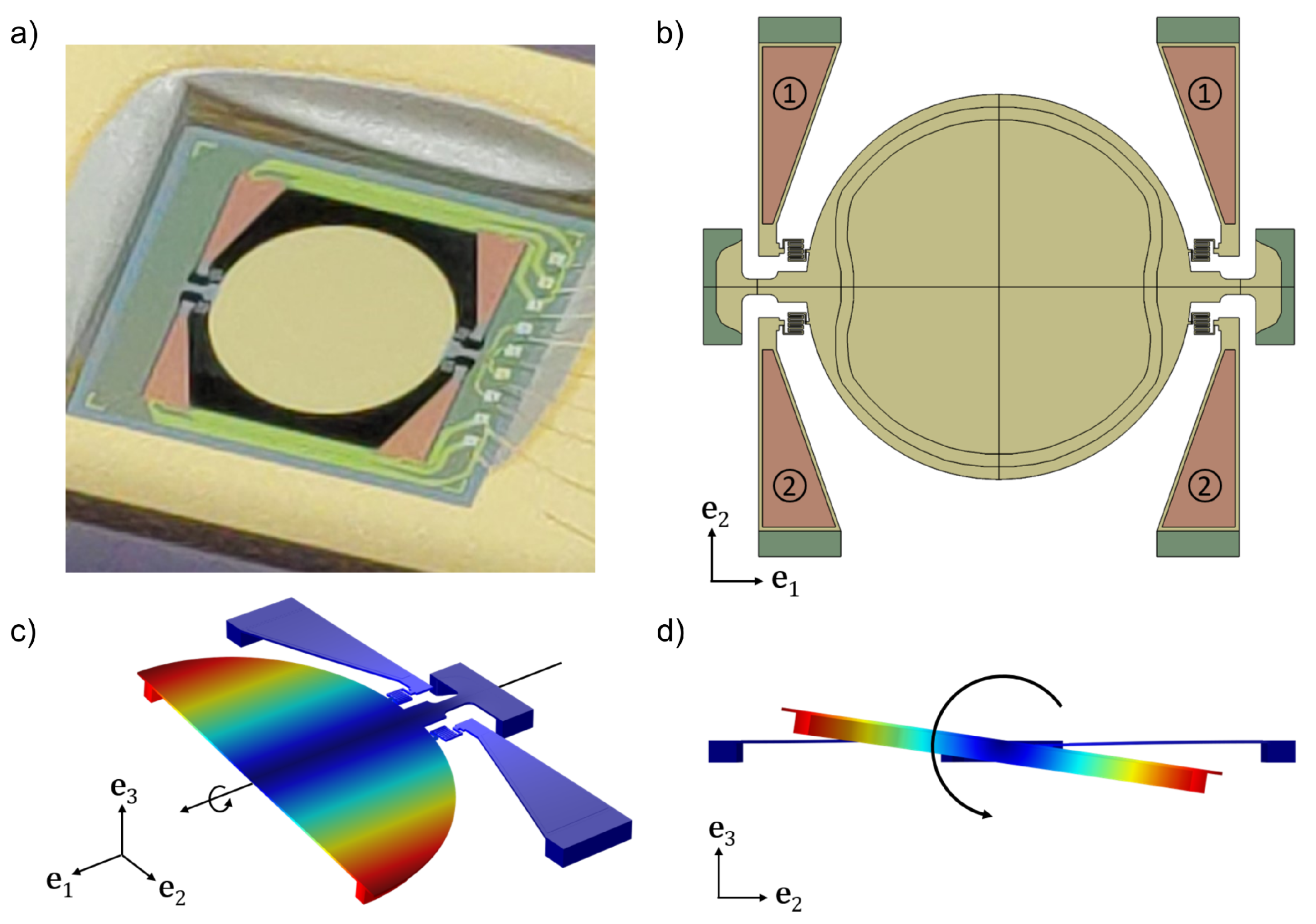
Figure 1 presents the first micromirror, hereafter denoted M1. The monocrystalline silicon layer of the device has a thickness of 20 m. The circular reflective surface of the device has a diameter of 3000 m, and a circular reinforcement is added beneath it to minimise dynamic deformations. The reflective surface is suspended by means of two torsional springs connected to the substrate. The main axes of the springs pass through the center of the mirror. The anchor points of the device are visible in green in Figure 1b. Actuation is achieved by means of four trapezoidal beams with PZT patches highlighted in orange in the image. Patches are organised in two groups labelled 1 and 2, respectively, as highlighted in Figure 1b. Upon actuation, the beams apply through the folded springs a vertical force that excites the torsional mode of the micromirror, as represented in Figure 1c,d. The associated resonance frequency is 1950 Hz.
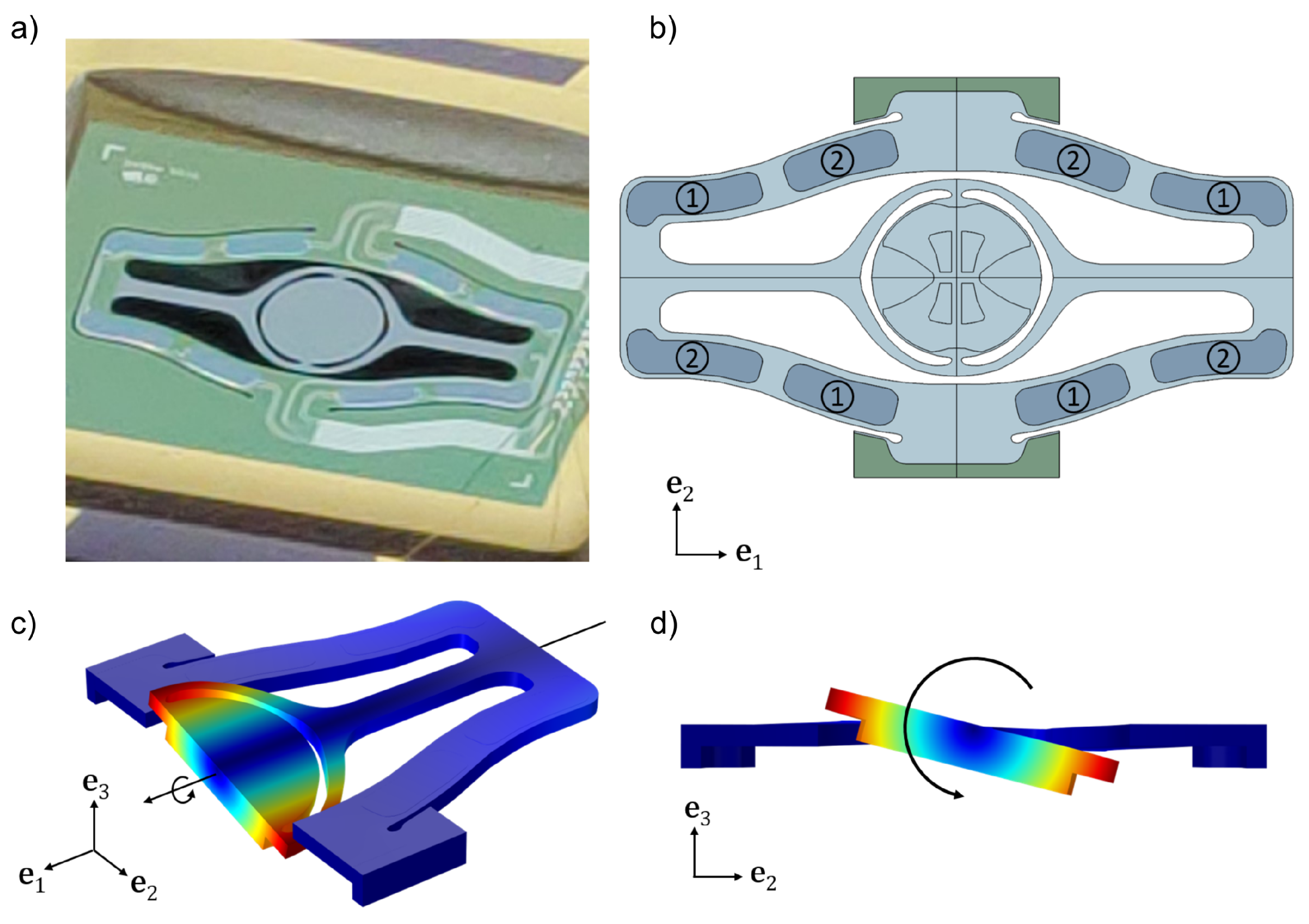
A picture of the second micromirror, hereafter labelled M2, is reported in Figure 2a and its geometry is schematically reported in Figure 2b. Material and orientation of the device are identical to mirror M1, but the thickness of the silicon layer is 150 m. The reflective surface is a disk with a diameter of 1600 m with a large reinforcement added on the bottom surface to minimise dynamic deformations. The disk is suspended to a flexible gimbal and the device is actuated at its torsional mode, that is a torsion around the axis, by means of eight PZT patches organised into two sets labelled 1 and 2. The resonance frequency of the torsional mode of the structure is 25,500 Hz.
Both mirrors are actuated by means of a unipolar potential law, applied with a shift of the signal phase by to the two patches groups 1 and 2. The actuation laws for the two patches are given by the formulas:
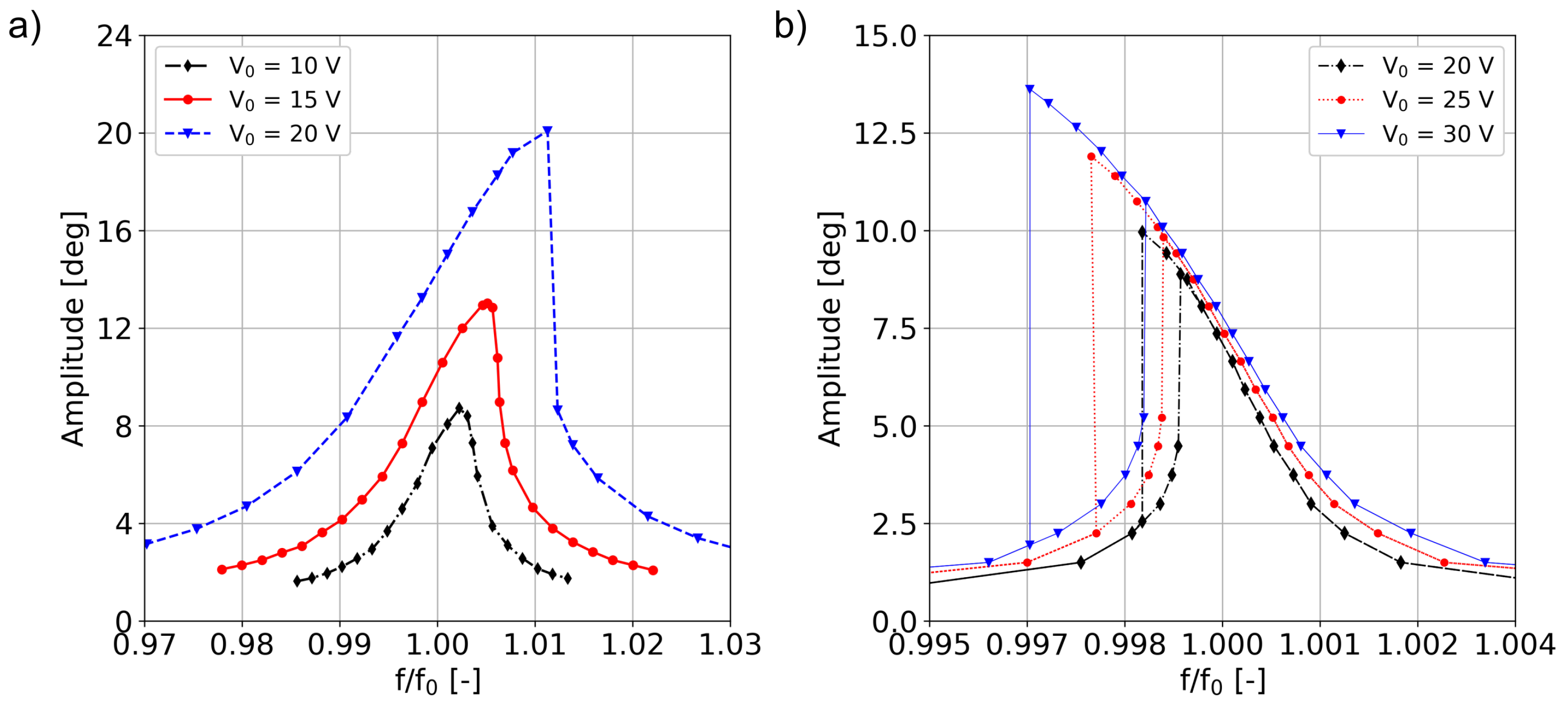
where denotes the maximum voltage and f is the excitation frequency. The Frequency Response Function (FRF) of the devices was experimentally determined from the opening angle of the micromirros by measuring the deflection of a laser beam incident on the device. The experiments being performed in frequency control allowed measuring only stable branches. For mirror M1, only a forward sweep of the frequency is performed. On the other hand, M2 was measured by performing both an upward and a downward sweep of the frequency. The FRF of mirror M1 is reported in Figure 3a, where the maximum tilting angle for a given frequency is reported. The frequency axis is normalised by the eigenfrequency of the torsional mode, that is 1950 Hz. As highlighted in the chart, the micromirror shows hardening behaviour with formation of an unstable branch for values above 15 V, which is highlighted in the experimental data by the sudden amplitude jump. The dynamic response of mirror M2 is shown in Figure 3b. Contrary to mirror M1, this device shows softening behaviour and it shows an unstable branch at any excitation voltage value. This different behaviour is mainly due to the fact that the axis of rotation is not clearly defined in M2, and the large eccentric reinforcement underneath the mirror induces a coupling with translational motions, thus reducing the apparent stiffness. Regarding the data reported in Figure 3b, the excitation frequency is normalised by the resonance frequency of the torsional mode of the device, that is 25,500 Hz.
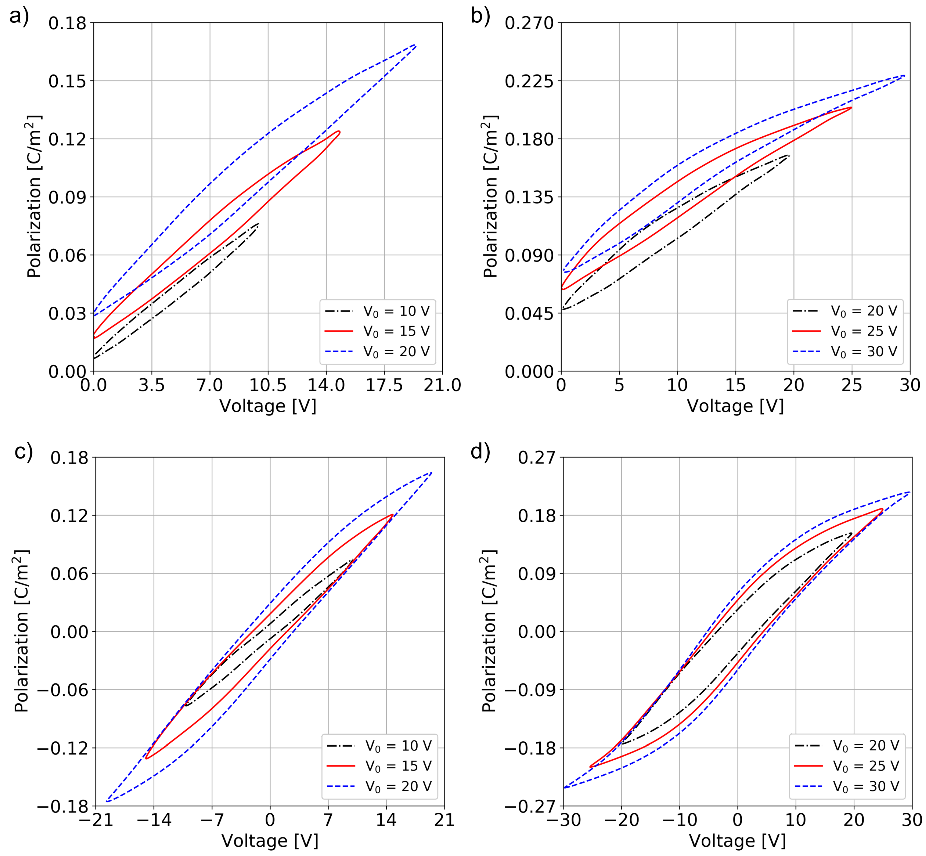
As reported in Section 3, modelling of piezoelectric materials with the technique proposed in [14] requires the knowledge of the time history of the average polarization field within the piezoelectric material used to actuated the device. Therefore, the average polarization P was measured on one PZT patch for each device using a standard Sawyer–Tower circuit [14,25] for each value in increasing order. It is worth stressing that the shape of the hysteresis loops is rather thin and somehow similar to that of relaxor ferroelectrics. This behaviour can be justified considering that the sol-gel deposited PZT considered herein presents rather small ferroelectric domains which have a progressive switching, as recently discussed in [26].
Results regarding the fifth cycle collected during both unipolar and bipolar cycles for both devices are reported in Figure 4. The data show the classical hysteretic behaviour of ferroelectric materials, highlighting the nonlinear response of the material with respect to the applied voltage.
To avoid fatigue effects due to switching between negative and positive values of the polarisation, the PZT patches are normally operated with unipolar cycles. This implies that only unipolar polarisation cycles will be used to model these devices. Elaborating the hysteresis cycles in Figure 4, one can obtain the polarisation histories and imposed on the two patches, respectively, assuming that the polarisation is not affected by the frequency of the voltage law, which is reasonable for the working frequencies of these devices.
3. Model for Material and Geometrical Nonlinearities
According to Landau–Devonshire theory [13,27], the polarisation induces inelastic strains
where denotes the electrostrictive tensor [13]. When a voltage bias is applied to the electrodes, the electric field in the very thin PZT layer can be expressed as , with h thickness of the PZT layer. It is also reasonable to postulate that, on average, the polarisation of the film also has the single component , leading to a simplified expression of the polarisation strain components in Equation (2):
where a Voigt notation is adopted.
According to Saint Venant-Kirchhoff constitutive law, the second Piola–Kirchhoff stress tensor in the piezo film can be expressed as:
where denotes the fourth-order elasticity tensor [24]. The difference between the total Green–Lagrange strain tensor and denotes elastic strains. Total strains are defined in terms of the displacement gradient as:
According to Equation (3), under the assumption of transverse isotropic behaviour, the non-vanishing components of are
In tensor form:
Equation (5) holds pointwise in the PZT thin film, but experiments only provide and for each piezo patch, i.e. the time history of an average polarisation. Secondly, even if the value of P should also depend on the local elastic strain , we introduce the assumption that, in presence of extremely large electric fields, the influence of on P can be neglected. As a consequence and acquire the meaning of pointwise polarisation in the film.
We choose to enforce equilibrium conditions for the micromirrors in large rotations applying the principle of virtual power in reference (undeformed) configuration:
where is the domain in material configuration, is the density in material configuration, is a test function defined over the space of functions that vanishes on the boundary where Dirichlet boundary conditions are prescribed on the unknown displacements , is the transformation gradient, denotes the ith piezoelectric material domain and is the number of piezoelectric domains. Equation (7) highlights that the different actuation patches of the system can be subjected to different actuation voltage histories. generates nonlinearities up to cubic order in terms of the unknown displacement field and it is the main source of geometrical nonlinearities. The last integral in Equation (7) represents the forcing term due to the piezoactuation, with provided by experiments as commented above. It is worth mentioning that, according to the unipolar polarisation histories in Figure 4, the polarisation oscillates around a non-zero average value which has the same effect as a large pre-stress on the structure. As a consequence, has the same order of magnitude as the terms of internal forces in the left hand side and cannot be neglected. In a reduced order model, such as the one formulated in [14], the average value of the polarisation gets automatically filtrated by the skewsymmetric test function. However, in a full-order simulation such as the one discussed herein, the additional term is required to avoid spurious frequency shifts.
Equation (7) is discretised with a standard finite element approach leading the following system of time-dependent coupled differential equations:
where is the mass matrix, is the nodal acceleration vector, is the nonlinear internal force vector, is a vector of piezoelectric forces and is a piezoelectric stiffness. We add damping in the form and select a Rayleigh model:
to reproduce the experimentally measured quality factor Q for the resonating mode. is the torsional mode eigenfrequency.
We stress once more that the piezoelectric force is made by two terms: the first term is constant with respect to the displacement, while the second is linear with respect to the displacement itself. This last term implies that, since the polarisation is a function of time, the stiffness of the system is modulated in time by the piezoelectric force.
Numerical Solution
The system reported in Equation (8) is solved with the HBM [20,21,28,29,30,31,32]. We assume that the solution in time can be represented by a truncated Fourier series of order N:
where N is the order of the harmonic expansion, , , are vectors collecting the unknown coefficients of the expansion, and . Their values are computed by substituting Equation (9) into Equation (8) and by projecting the residual on the same Fourier basis used for the displacement field:
for n = 1:N. T is the period of oscillation. The large-scale nonlinear system is solved with a Newton–Raphson method [20]. In particular, is itself expressed in the same Fourier basis as in (9) and integrals over the time period of the cubic nonlinear terms and of their linearisation are performed exactly with the trapezoidal rule since the latter method is exponentially convergent for periodic functions.
Regarding the expansion order of the Fourier series, a sufficiently high N is required to analyse micromirrors that experience large rotations, of the order of rad. This limitation can be intuitively explained by simply considering a rigid mirror rotating about a fixed axis z, with angle , where is the maximum rotation angle. In Cartesian coordinates, the displacement components of a material point with radial distance r from the axis of rotation can be expressed with a truncated series as:
where N should be selected to guarantee the desired accuracy. Since this amounts to considering terms up to , in the trigonometric series (9). All the simulations reported in the following sections are performed with .
4. Numerical Results
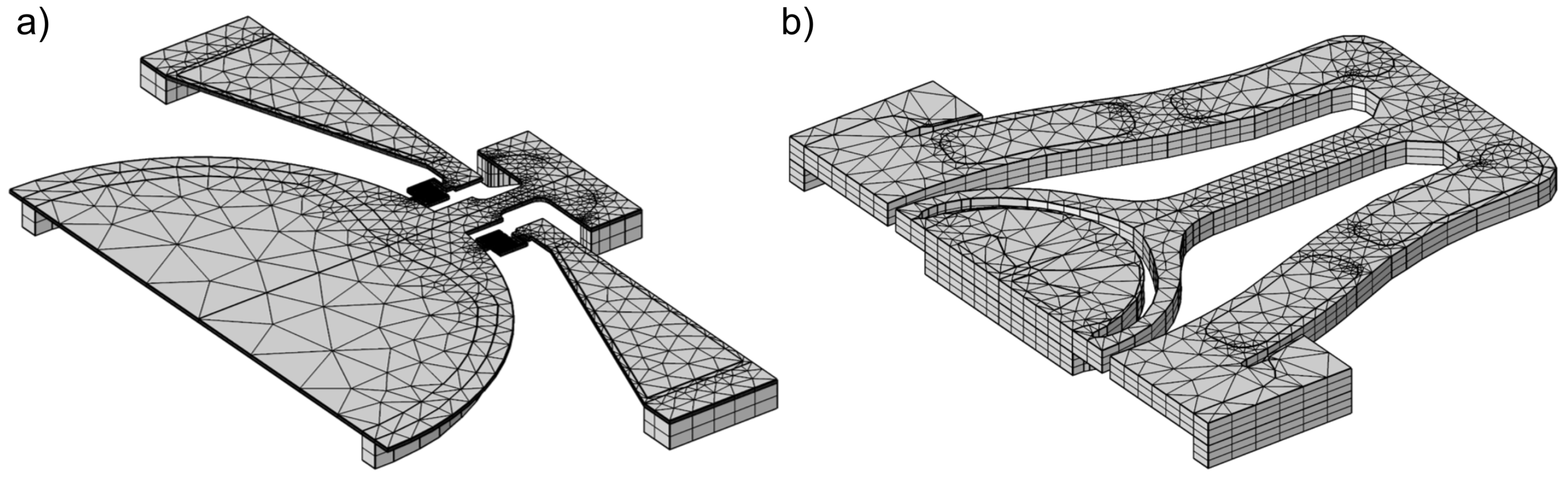
The meshes adopted for the numerical simulation are illustrated in Figure 5. They are made by quadratic wedge elements with a total of 35,969 and 29,280 nodes, respectively, corresponding to 107,907 and 87,840 unknowns for each Fourier component. If is selected, this gives a total of 1,186,977 and 966,240 unknowns in the nonlinear system (10) for M1 and M2, respectively.
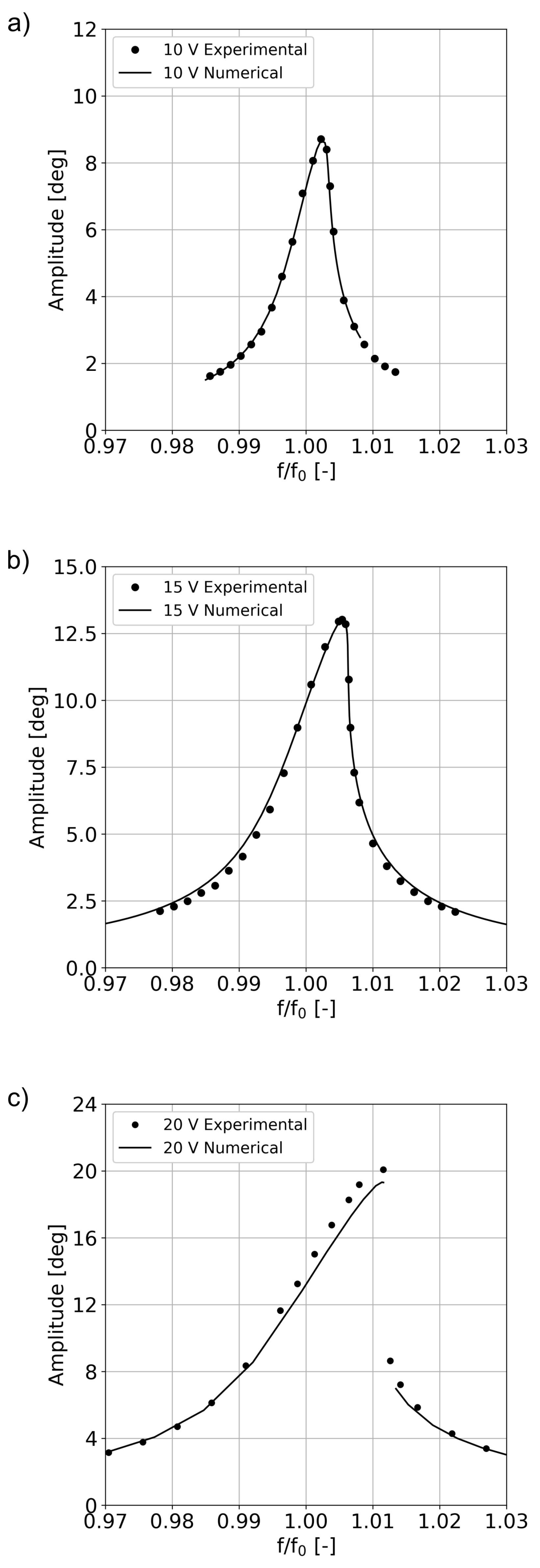
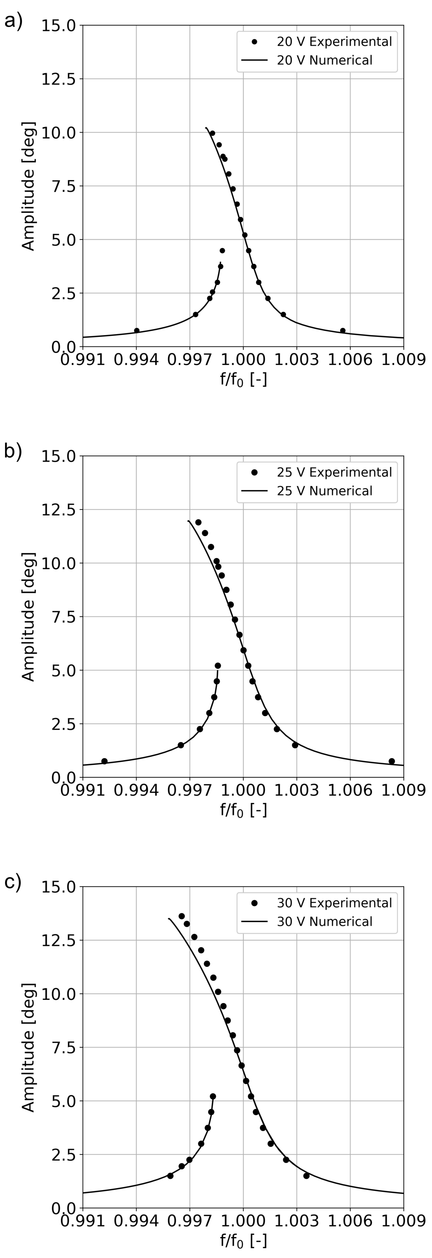
Numerical simulations were run with values equal to 10, 15 and 20 V for mirror M1 and 20, 25 and 30 V for mirror M2. Mechanical properties for silicon were taken from Hopcroft [24]. On the other hand, since very limited data are available for the material properties of PZT, the Young modulus GPa and Poisson coefficient were selected to guarantee the best possible agreement with experiments. The piezoelectric coefficients values and correspond to the electrostrictive coefficients taken from [13] for a mole fraction of PbTiO equal to .
An important parameter of the model is the damping, which is quantified here by the quality factor Q associated to the torsional mode of the structure. In the present work Q was calibrated on the basis of experimental data using the simple formula provided by Davis [15] under the assumption of linear damping. The estimated quality factors are summarised in Table 1.
The comparison between numerical and experimental results is reported for mirror M1 in Figure 6. The results obtained for mirror M2 are collected in Figure 7.
Several remarks are worth stressing. Both experiments and numerical tests were run in frequency control, hence unstable branches could not be detected. A continuation procedure, as proposed in [20], could be implemented to follow the frequency response function beyond the folds.
The numerical method predicts the correct amplitude also far from resonance, a regime which is only minimally affected by the quality factors. This represents a strong validation of the piezoactuation model. The simulations also correctly capture the frequency shift of the peaks and the insurgence of instabilities (i.e., folds in the frequency response function), which is a primary feature of the device.
Furthermore, the correct bandwidth of the numerical curves implies that the assumption of linear damping is reasonable at least as a first approximation to model dissipation for the present device, even though a dependence of Q on the maximum opening would be more adequate.
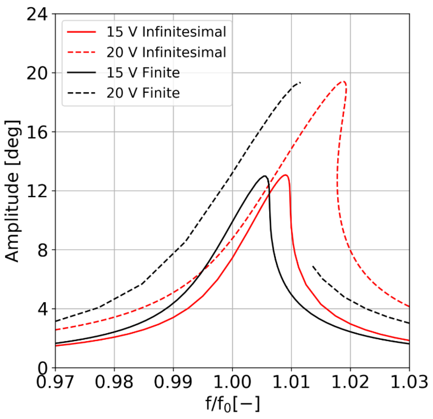
Finally, we focus on the effect of the term on the predicted response of the structure. As mentioned in Section 3, this term is required to avoid spurious frequency shifts that would otherwise be observed in the numerical curves, an effect which is often present in pre-stressed structures. The results are shown in Figure 8, highlighting the remarkable impact that the large displacements formulation has on the computed FRFs. In particular, we observe that nonlinearity and maximum amplitude are preserved in both models and that the only difference between the two curves is the shift in resonant frequency of the structure.
5. Conclusions
In this work, we address the full-order simulation of piezoelectric micromirrors oscillating at large rotations around a fast axis. Material nonlinearities, due to the hysteretic behaviour of the ferroelectric material, are modelled with the formulation recently proposed in [14]. Geometrical nonlinearities, on the contrary, are modelled with the classical Lagrangian equilibrium condition, which allows for large displacements (and small strains) and generates a formulation with nonlinearities up to cubic order. The resulting model is discretised by means of the finite element method and the associated system of nonlinear equations is solved through the HBM. An experimental campaign was run on two different micromirrors to extract both the frequency response function and the polarisation history in the piezo-patches. The excellent agreement between numerical and experimental data highlights that the proposed approach efficiently models the nonlinear dynamic response of piezo microsystems. In particular, the formulation correctly predicts the softening and hardening behaviour of the mirrors both qualitatively and quantitatively along with the nonlinear shift of the resonating frequency. Only the quality factor of the device was extracted from experimental data according to a simplified assumption of linear damping. Even though this assumption turns out to be sufficiently accurate to predict the overall mirror response, a numerical and experimental campaign is under way using ring-down measurements of the devices and dedicated Arbitrary Lagrangian-Eulerian Navier-Stokes Simulations.
Author Contributions
Conceptualization, A.O. and A.F.; methodology, A.O. and A.F.; software, A.O. and A.F.; validation A.O. and A.F.; formal analysis, A.O. and A.F.; investigation, N.B. and R.C.; resources, N.B. and R.C.; data curation, A.O. and A.F.; writing—original draft preparation, A.O. and A.F.; writing—review and editing, A.O. and A.F.; visualization, A.O. and A.F.; supervision, A.F.; project administration, A.F.; funding acquisition, A.F. All authors have read and agreed to the published version of the manuscript.
Funding
This research received no external funding.
Conflicts of Interest
The authors declare no conflict of interest.
References
- Niesten, M.; Masood, T.; Miller, J. Scanning laser beam displays based on 2D MEMS. Proc. SPIE 2010, 7723, 7723U. [Google Scholar]
- Qiu, Z. MEMS-based Medical Endomicroscopes. IEEE J. Sel. Top. Quantum Electron. 2015, 21, 6800216. [Google Scholar] [CrossRef]
- Frangi, A.; Guerrieri, A.; Carminati, R.; Mendicino, G. Parametric resonance in electrostatically actuated micromirrors. IEEE Trans. Ind. Electron. 2016, 64, 1544–1551. [Google Scholar] [CrossRef]
- Carr, D.W.; Evoy, S.; Sekaric, L.; Craighead, H.G.; Parpia, J.M. Parametric amplification in a torsional microresonator. Appl. Phys. Lett. 2000, 77, 1545–1547. [Google Scholar] [CrossRef] [Green Version]
- Rhoads, J.F.; Shaw, S.W.; Turner, K.L.; Moehlis, J.; DeMartini, B.E.; Zhang, W. Generalized parametric resonance in electrostatically actuated microelectromechanical oscillators. J. Sound Vib. 2006, 296, 797–829. [Google Scholar] [CrossRef]
- DeMartini, B.E.; Rhoads, J.F.; Turner, K.L.; Shaw, S.W.; Moehlis, J. Linear and nonlinear tuning of parametrically excited MEMS oscillators. J. Microelectrom. Syst. 2007, 16, 310–318. [Google Scholar] [CrossRef]
- Krylov, S.; Harari, I.; Cohen, Y. Stabilization of electrostatically actuated microstructures using parametric excitation. J. Micromech. Microeng. 2005, 15, 1188–1204. [Google Scholar] [CrossRef]
- Frangi, A.; Guerrieri, A.; Boni, N.; Carminati, R.; Soldo, M.; Mendicino, G. Mode Coupling and Parametric Resonance in Electrostatically Actuated Micromirrors. IEEE Trans. Ind. Electron. 2018, 65, 5962–5969. [Google Scholar] [CrossRef]
- Cui, Z.; Wang, X.; Li, Y.; Tian, G.Y. High sensitive magnetically actuated micromirrors for magnetic field measurement. Sens. Actuators A Phys. 2007, 138, 145–150. [Google Scholar] [CrossRef]
- Zhu, Y.; Liu, W.; Jia, K.; Liao, W.; Xie, H. A piezoelectric unimorph actuator based tip-tilt-piston micromirror with high fill factor and small tilt and lateral shift. Sens. Actuators A Phys. 2011, 167, 495–501. [Google Scholar] [CrossRef]
- Fichtner, S.; Wolff, N.; Lofink, F.; Kienle, L.; Wagner, B. AlScN: A III-V semiconductor based ferroelectric. J. Appl. Phys. 2019, 125, 114103. [Google Scholar] [CrossRef]
- Leontsev, S.O.; Eitel, R.E. Dielectric and Piezoelectric Properties in Mn-Modified (1-x)BiFeO3–xBaTiO3 Ceramics. J. Am. Ceram. Soc. 2009, 92, 2957–2961. [Google Scholar] [CrossRef]
- Haun, M.J.; Furman, E.; Jang, S.J.; McKinstry, H.A.; Cross, L.E. Thermodynamic theory of PbTiO3. J. Appl. Phys. 1987, 62, 3331–3338. [Google Scholar] [CrossRef]
- Frangi, A.; Opreni, A.; Boni, N.; Fedeli, P.; Carminati, R.; Merli, M.; Mendicino, G. Nonlinear Response of PZT-actuated Resonant Micromirrors. J. Microelectrom. Syst. 2020, 29, 1421–1430. [Google Scholar] [CrossRef]
- Davis, W.O. Measuring Quality Factor From a Nonlinear Frequency Response with Jump Discontinuities. J. Microelectrom. Syst. 2011, 20, 968–975. [Google Scholar] [CrossRef]
- Touzé, C.; Thomas, O.; Chaigne, A. Hardening/softening behaviour in non-linear oscillations of structural systems using non-linear normal modes. J. Sound Vib. 2004, 273, 77–101. [Google Scholar] [CrossRef] [Green Version]
- Touzé, C.; Amabili, M. Non-linear normal modes for damped geometrically non-linear systems: Application to reduced-order modeling of harmonically forced structures. J. Sound Vib. 2006, 298, 958–981. [Google Scholar] [CrossRef] [Green Version]
- Kerschen, G.; Peeters, M.; Golinval, J.C.; Vakakis, A.F. Nonlinear normal modes. Part I: A useful framework for the structural dynamicist. Mech. Syst. Signal Process. 2009, 23, 170–194. [Google Scholar] [CrossRef] [Green Version]
- Peeters, M.; Viguié, R.; Sŕandour, G.; Kerschen, G.; Golinval, J.C. Nonlinear normal modes. Part II: Toward a practical computation using numerical continuation techniques. Mech. Syst. Signal Process. 2009, 23, 195–216. [Google Scholar] [CrossRef] [Green Version]
- Detroux, T.; Renson, L.; Masset, L.; Kerschen, G. The harmonic balance method for bifurcation analysis of large-scale nonlinear mechanical systems. Comput. Methods Appl. Mech. Engrg. 2015, 296, 18–38. [Google Scholar] [CrossRef] [Green Version]
- Renson, L.; Kerschen, G.; Cochelin, B. Numerical computation of nonlinear normal modes in mechanical engineering. J. Sound Vib. 2016, 364, 177–206. [Google Scholar] [CrossRef] [Green Version]
- García-Salda na, J.D. A theoretical basis for the harmonic balance method. J. Differ. Equ. 2013, 254, 67–80. [Google Scholar] [CrossRef]
- Lu, J.; Zhao, X.; Yamada, S. Harmonic Balance Finite Element Method: Applications in Nonlinear Electromagnetics and Power Systems; John Wiley & Sons: Hoboken, NJ, USA, 2016. [Google Scholar]
- Hopcroft, M.A.; Nix, W.D.; Kenny, T.W. What is the Young’s Modulus of Silicon? J. Microelectrom. Syst. 2010, 19, 229–238. [Google Scholar] [CrossRef] [Green Version]
- Bouregba, R.; Poullain, G. Numerical extraction of the true ferroelectric polarization due to switching domains from hysteresis loops measured using a Sawyer-Tower circuit. Ferroelectrics 2002, 274, 165–181. [Google Scholar] [CrossRef]
- Fedeli, P.; Cuneo, F.; Magagnin, L.; Nobili, L.; Kamlah, M.; Frangi, A. On the simulation of the hysteresis loop of polycrystalline PZT thin films. Smart Mater. Struct. 2020, 29, 095007. [Google Scholar] [CrossRef]
- Devonshire, A.F. Theory of ferroelectrics. Adv. Phys. 1954, 3, 1954. [Google Scholar] [CrossRef]
- Hayashi, C. Nonlinear Oscillations in Physical Systems; Princeton University Press: Princeton, NJ, USA, 2014; ISBN 10: 978-0-691-61120-4. [Google Scholar]
- Genesio, R.; Tesi, A. Harmonic balance methods for the analysis of chaotic dynamics in nonlinear systems. J. Vib. Acoust. 1992, 28, 531–548. [Google Scholar] [CrossRef]
- Nacivet, S.; Pierre, C.; Thouverez, F.; Jézéquel, L. A dynamic Lagrangian frequency-time method for the vibration of dry-friction-damped systems. J. Sound Vib. 2003, 265, 201–219. [Google Scholar] [CrossRef] [Green Version]
- Thomas, O.; Lazarus, A.; Touzé, C. A harmonic-based method for computing the stability of periodic oscillations of non-linear structural systems. IDETC-CIE 2010 2010, 44137, 883–892. [Google Scholar]
- Krack, M.; Gross, J. Harmonic Balance for Nonlinear Vibration Problems; Springer: Cham, Switzerland, 2019. [Google Scholar]
Figure 1.
Image of mirror M1 (a); and schematic representation of the device geometry (b). The silicon reflective surface is coloured in light yellow. Anchor points are coloured in green. Piezoelectric patches appear in orange in the picture. The numbers over the piezoelectric patches highlight the actuation groups. (c,d) Displacement field associated to the torsional mode of the structure.

Figure 2.
Image of mirror M2 (a); and schematic representation of the device geometry (b). The silicon reflective surface is coloured in light blue. Anchor points are coloured in green. Piezoelectric patches appear in dark blue in the picture. The numbers over the piezoelectric patches highlight the actuation groups. (c,d) Displacement field associated to the torsional mode of the structure.

Figure 3.
Frequency response function measured for mirror M1 (a) and mirror M2 (b).

Figure 4.
(a,b) Polarisation data measured during unipolar cycles for mirrors M1 and M2, respectively. (c,d) Polarisation data measured during bipolar cycles for mirror M1 and M2, respectively.
Figure 4.
(a,b) Polarisation data measured during unipolar cycles for mirrors M1 and M2, respectively. (c,d) Polarisation data measured during bipolar cycles for mirror M1 and M2, respectively.

Figure 5.
Finite element discretisations adopted for M1 (a) and M2 (b).

Figure 6.
Comparison between experimental data and numerical results for mirror M1 for values of 10 V (a) 15 V (b), and 20 V (c).
Figure 6.
Comparison between experimental data and numerical results for mirror M1 for values of 10 V (a) 15 V (b), and 20 V (c).

Figure 7.
Comparison between experimental data and numerical results for mirror M2 for values of 20 V (a) 25 V (b), and 30 V (c).
Figure 7.
Comparison between experimental data and numerical results for mirror M2 for values of 20 V (a) 25 V (b), and 30 V (c).

Figure 8.
Comparison between numerical results obtained for a piezoelectric force formulated within the small displacements assumption (Infinitesimal) and the one computed within the framework of large transformations (Finite).
Figure 8.
Comparison between numerical results obtained for a piezoelectric force formulated within the small displacements assumption (Infinitesimal) and the one computed within the framework of large transformations (Finite).


Table 1.
Quality factors obtained from Equation (14) of [15] under the assumption of linear damping.
Table 1.
Quality factors obtained from Equation (14) of [15] under the assumption of linear damping.
| M1 | M2 | |||||
|---|---|---|---|---|---|---|
| V [V] | 10 | 15 | 20 | 20 | 25 | 30 |
| Q [-] | 186 | 143 | 105 | 1386 | 1200 | 1092 |
Publisher’s Note: MDPI stays neutral with regard to jurisdictional claims in published maps and institutional affiliations. |
© 2021 by the authors. Licensee MDPI, Basel, Switzerland. This article is an open access article distributed under the terms and conditions of the Creative Commons Attribution (CC BY) license (http://creativecommons.org/licenses/by/4.0/).
Share and Cite
MDPI and ACS Style
Opreni, A.; Boni, N.; Carminati, R.; Frangi, A. Analysis of the Nonlinear Response of Piezo-Micromirrors with the Harmonic Balance Method. Actuators 2021, 10, 21. https://0-doi-org.brum.beds.ac.uk/10.3390/act10020021
AMA Style
Opreni A, Boni N, Carminati R, Frangi A. Analysis of the Nonlinear Response of Piezo-Micromirrors with the Harmonic Balance Method. Actuators. 2021; 10(2):21. https://0-doi-org.brum.beds.ac.uk/10.3390/act10020021
Chicago/Turabian StyleOpreni, Andrea, Nicolò Boni, Roberto Carminati, and Attilio Frangi. 2021. "Analysis of the Nonlinear Response of Piezo-Micromirrors with the Harmonic Balance Method" Actuators 10, no. 2: 21. https://0-doi-org.brum.beds.ac.uk/10.3390/act10020021
Note that from the first issue of 2016, this journal uses article numbers instead of page numbers. See further details here.