Article

Dynamic Performance Analysis of a Compact Annular-Radial-Orifice Flow Magnetorheological Valve and Its Application in the Valve Controlled Cylinder System

Key Laboratory of Conveyance and Equipment, Ministry of Education, East China Jiaotong University, Nanchang 330013, China
*
Author to whom correspondence should be addressed.
Submission received: 18 April 2021 / Revised: 7 May 2021 / Accepted: 14 May 2021 / Published: 17 May 2021
(This article belongs to the Section Actuators for Land Transport)

Abstract

:
A compact annular-radial-orifice flow magnetorheological (MR) valve with variable radial damping gaps was proposed, and its structure and working principle were also described. Firstly, a mathematical model of pressure drop was established as well to evaluate the dynamic performance of the proposed MR valve. Sequentially, the pressure drop distribution of the MR valve in each flow channel was simulated and analyzed based on the average magnetic flux densities and yield stress along the damping gaps through finite element method. Further, the experimental test rig was setup to explore the pressure drop performance and the response characteristic of the MR valve and to investigate dynamic performance of the valve controlled cylinder system under different radial damping gaps. The experimental results revealed that the pressure drop and response time of the MR valve augment significantly with the increase of applied current and decrease of the radial damping gap. In addition, the damping force of the proposed MR valve controlled cylinder system decrease with the increase of the radial damping gap. The maximum damping force can reach about 4.72 kN at the applied current of 2 A and the radial damping gap of 0.5 mm. Meanwhile, the minimum damping force can reach about 0.67 kN at the applied current of 0 A and the radial damping gap of 1.5 mm. This study clearly demonstrates that the radial damping gap of the MR valve is the key parameter which directly affects the dynamic characteristics of the valve controlled cylinder system, and the proposed MR valve can meet the requirements of different working conditions by changing the radial damping gaps.

1. Introduction

Magnetorheological (MR) fluid is a controllable intelligent fluid, which is a kind of suspension formed by dispersing soft magnetic particles with high permeability and low hysteresis in non-magnetic liquid [1]. As a versatile intelligent material, the MR fluid can change from liquid state to semi-solid state in a few milliseconds under the action of external magnetic field, and this change is continuously reversible [2]. Some inherent rheological properties of MR fluid, such as fast response time, continuous reversibility, and strong controllability have widely used such a huge amount of engineering MR equipment, such as MR valve [3,4,5], MR damper [6,7], MR brake [8], and so on. The MR fluids can also be widely employed in automotive industry [9,10,11] and biomedical equipment [12] based on a variety of MR devices.
In general, a conventional MR valve is composed of magnetic body, magnetic spool, exciting coil, and flow channel. The geometric structure is a dominant factor effect on the pressure drop and dynamic performance of the MR valve. The geometric structure of MR valve varies greatly due to the different structure design, but its working principle is basically congruent. Therefore, for realizing a better dynamic performance, research on the structure and optimal design of MR valve is very important. Plenty of research has been carried out to explore structural design of the MR valve or parameter optimization on the existing structure.
According to the fluids flow paths of the typical MR valve, the structure of MR valve can be classified into annular flow, radial flow, and annular-radial hybrid flow. Grunwald et al. [13] performed the structural design and experimental analysis of the axial type MR valve, the experimental results showed that its pressure drop can reach 1.5 MPa at the current of 4.5 A. Hu et al. [14] developed a double coil MR valve, which can realize multi-stage pressure regulation by increasing the number of excitation coils. However, in order to obtain better damping performance of the annular flow MR valve, it is necessary to increase the length of damping gap or the number of coils, which will expand the overall size and enhance the complexity of its structure. To improve the utilization rate of magnetic field, Sahin et al. [15] presented a MR valve with disk damping gap, which mainly includes two fixed disks, winding frame, and excitation coil. The MR fluid flows in a disk-shaped damping gap between the two disks, and its flow direction was perpendicular to the magnetic field direction in the damping gap. The results show that the pressure drop adjustable range and response time of the disk MR valve are larger than those of the annular MR valve. Imaduddin et al. [16] developed the MR valve with complex curved flow channel, and which was composed of multiple annular, radial and orifice flow channels. Simulation and experimental results show that the maximum pressure drop of the proposed MR valve can be higher than 2.5 MPa when the outer diameter size is 50 mm. Hu et al. [17] investigated the MR valve with tunable damping gap between 1 mm and 2 mm. The valve can control the pressure drop of the MR valve in real time by switching the working position of the valve spool and the experimental investigation shows that the MR valve has wide regulating scope of pressure drop. To sum up, in the field of structure design, although the utilization of magnetic field can be employed to enhance in a limited space for meandering and damping adjustability MR valves, it also increases the complexity of the valve structure. Hence, the valve is easy cause blockage and will restrict the application of the MR valve.
In order to improve the performance of MR valves, optimization methodologies have been utilized in the design of MR valves. For instance, Shou et al. [18] considered a design method based on complete dynamic model of the magnetorheological energy absorber (MREA) equipped with disc springs. The design objective was to determine the geometric dimensions of the disc spring and MR valve, so as to return the piston to the initial position as soon as possible after the rapid impact loading. The magnetic flux density in the flux gap was also analyzed by using Kirchhoff law and flux conservation law. Finally, the effectiveness of the design method was verified by comparing the MREA behavior of test and full dynamic modeling. Armin et al. [19] focused on the optimum designing method of single coil axial flow MR valve with specific volume constraints by combining the finite element model, experimental design, and response surface technology. The approximate response surface function was proposed depending on the magnetic flux density on the activation length of the orifice plate of the MR valve, which was based on the identified design variables. Additionally, the sequential quadratic programming technology and genetic algorithm were utilized to obtain the global optimal geometric parameters of the MR valve. Zhang et al. [20] presented a type of MR valve controlled damper (MRVD) and its top-down design method was proposed from two aspects of structural design and system synthesis. The result exhibitions that the driving power of MRVD prototype vehicle was 3W and the MRVD fluid was 6.1ml, which meets the requirements of the target passenger car. Manjeet et al. [21] used the regression model to fit the flux density of the active and the core areas of the MR valve. Simulation experiments were carried out by using different experimental design (DoE) techniques and ANSYS to obtain the regression model. Finally, both optimal results and initial results obtained from the constant relative permeability approximation magnetic circuit were compared.
Deserved to be mentioned, the MR valves with damping gaps of annular and radial or meandering are fixed, which is difficult to explore the dynamic property of MR valve by changing the damping gaps. In terms of structural design of MR valve, the thickness of the damping gap is a critical factor to affect the dynamic property of the MR valve [22,23]. If the damping gap is too large, it will enlarge the magnetoresistance at the damping gap and will reduce the pressure drop of the MR valve. If the damping gap is too small, although higher pressure drop can be obtained, it will make the internal channel prone to blockage and makes it difficult for the MR fluid to pass through the damping gap. In other words, the design of a MR valve considering variable damping gaps has great research significance. In general, the reasonable damping gap ranges between 0.5 mm and 1.5 mm [3,23].
The main technical contribution of this article is to propose a compact annular-radial-orifice flow MR valve which consists of an annular flow channel, a radial flow channel, and a small orifice flow channel in sequence. Firstly, the magnetic circuit of the developed MR valve is designed, modeled, and simulated by using the finite element method (FEM). Then, the magnetic flux density distribution and pressure drop in each liquid flow channel and the dynamic performance of the MR valve controlled cylinder system with four different radial damping gaps are analyzed. In addition, the pressure drop performance and response characteristics of the MR valves with different radial damping gaps are compared on the dynamic performance test rig. The proposed MR valve is connected to the valve controlled cylinder system as a bypass valve, and the dynamic performance of valve controlled cylinder systems is also experimentally analyzed.

2. Design and Development of a Compact Annular-Radial-Orifice Flow MR Valve

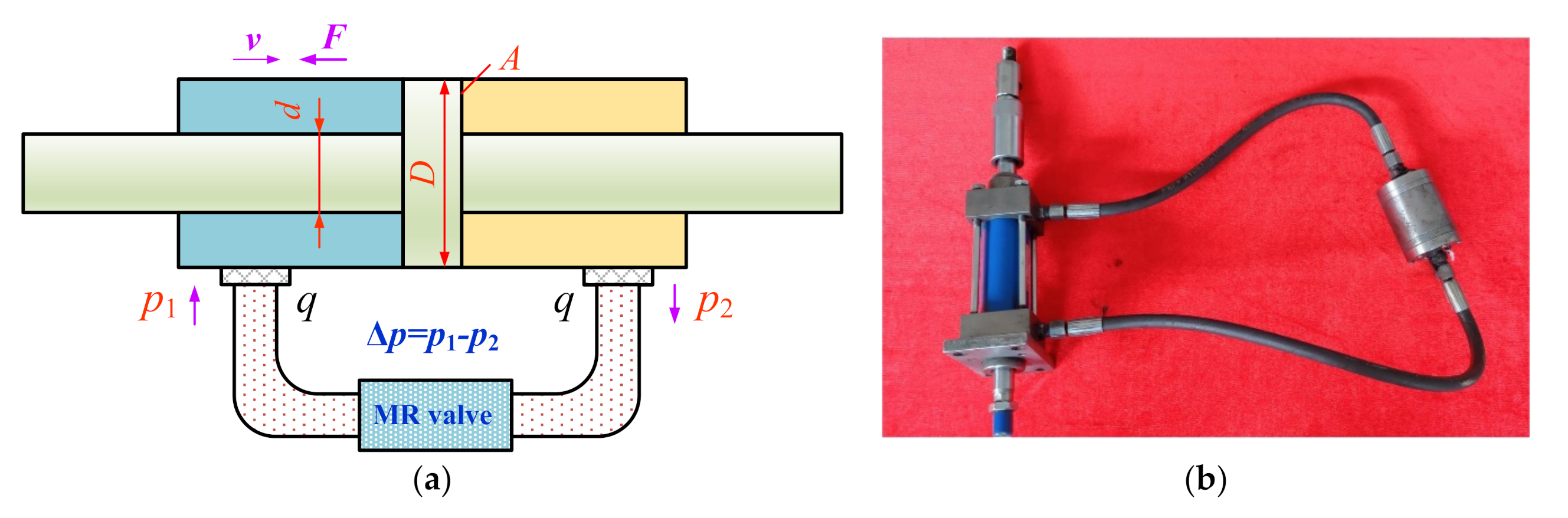
2.1. Principle and Structure Analysis

The detailed configuration of the compact annular-radial-orifice flow MR valve is shown in Figure 1. It is composed of three components, the valve spool, the coil, and the shell parts. According to the valve spool part, the positioning plate and the valve spool are connected by the screw thread and positioned through the shoulder, and the winding area is formed in the meantime. The magnetic disk is connected with the positioning plate through the sink screw, and the washer is placed between the magnetic disk and the positioning plate, which forms the radial damping gap. Meanwhile, the thickness of the washer can ensure the size of the radial damping gap; according to the coil part, the exciting coil is wound in the groove formed by the positioning plate and the valve spool and extends out through a small hole on the right end cover; according to the shell part, the left end cover, flow guided plate, and valve body are connected by screws, and the right end cover, valve spool and valve body are also connected by screws. When the valve spool part is coaxially positioned with the shell part, the annular damping gap is formed between the magnetic disk and the valve body.
This proposed MR valve is composed of an annular flow channel, a radial flow channel, and a small orifice flow channel in sequence. In working condition, the MR fluid flows through the left end cover, through the flow guided plate, the annular damping gap, and then flows through the radial damping gap to reach the inner hole of the valve spool, and finally flows out from the right end cover. The magnetic disk, valve body, and valve spool are made from the magnetic materials of No. 10 steel. The end covers, flow guided plate, positioning plate, and washer are made from non-magnetic materials of stainless steel. The MR valve can form a closed loop magnetic field because of the excitation coil applied in current, as shown in Figure 1. When a magnetic field is generated, the MR fluid flows through the fluid flow damping channels will immediately become chain solid state from Newtonian fluids state, which enhance the yield stress of the MR fluid and resulting in the flow of MR fluid is blocked, so that the pressure drop between the inlet and outlet of the MR valve is formed. In this way, the pressure drop of the MR valve can be controlled continually by adjusting the excitation current. In addition, the radial damping gap is changed by replacing four different sizes of washers. The purpose of the experiment is to verify that the radial damping gap is better than the annular damping gap and to investigate the influence of radial damping gap thickness on pressure drop, response time, and damping performance of the valve controlled cylinder system. Therefore, under the premise of ensuring the magnetic circuit meets the design requirements, the annular damping gap is fixed to 1.0 mm, and the radial damping gap are set to 0.5 mm, 0.8 mm, 1.0 mm, and 1.5 mm, respectively. The developed valve has outer diameter size of 62 mm and overall length of 80 mm.

2.2. Magnetic Circuit Analysis

Figure 2 displays the magnetic circuit diagram of the proposed MR valve. Assuming that the magnetic lines in the magnetic circuit are uniformly distributed and the magnetic flux leakage is not considered, the whole closed loop can be written as
Φ = Φ M R , a = Φ M R , r = Φ s t e e l
where Φ is the magnetic flux produced by excitation coil, ΦMR,a, and ΦMR,r are the magnetic flux of the MR fluid in the annular and radial damping gap, respectively, and Φsteel is the magnetic flux of the magnetic conducting components, such as the valve spool, magnetic disk, valve body, and other magnetic conducting materials.
According to Kirchhoff’s law for the relevant ampere turns, the corresponding magnetic circuit can be determined by
N c I = c H d l = i = 1 n H i l i
where Nc is the number of turns of the excitation coil, I is the current applied to excitation coil, Hi and li represent the magnetic field intensity and the effective length of part i of in magnetic circuit, respectively. On the other hand, the magnetic flux in the coil can be expressed as follows
Φ = c B d S = B i S i
where Bi and Si represent the magnetic flux density and cross-sectional area of part i of in magnetic circuit, respectively.
The effective length li of each part of the magnetic circuit can be obtained by
l 1 = L t d t c , l 2 = t d , l 3 = g r , l 4 = 0.5 L a , l 5 = R g a t h 0.5 R d 0.5 R 0 , l 6 = g a , l 7 = 0.5 t h , l 8 = L + 0.5 L a + g r t c , l 9 = 0.5 t c , l 10 = R 0.5 t h 0.5 R c 0.5 R 0 , l 11 = 0.5 t c
The cross-sectional area of each part perpendicular to the magnetic line can be calculated by
S 1 = S 11 = π [ R c 2 R 0 2 ] S 2 = S 4 = π [ R d 2 R 0 2 ] S 3 = S M R , r = π [ R d 2 R 0 2 ] S 5 = π ( R g a t h + 0.5 R d + 0.5 R 0 ) L a S 6 = S M R , a = 2 π ( R t h 0.5 g a ) L a S 7 = 2 π ( R 0.75 t h ) L a S 8 = S 9 = π [ R 2 ( R c + W c ) 2 ] S 10 = π ( R 0.5 t h + 0.5 R c + 0.5 R 0 ) t c
where SMR,a and SMR,r are the cross-sectional area of the annular and radial damping gap, respectively.
According to the electromagnetic theory, the relationship between magnetic flux density B and magnetic field intensity H can be expressed by the following formula
B i = μ 0 μ i H i
here, μ0 is the absolute permeability of vacuum, and its value is 4π × 107 TmA1; μi is the relative permeability of magnetic materials in each part.
The magnetoresistance Ri of each part in the magnetic circuit can be expressed as
R i = l i μ 0 μ i S i
Therefore, Equation (2) can be further expressed as
N c I = i = 1 n H i l i = i = 1 n B i μ 0 μ i l i = i = 1 n l i μ 0 μ i S i Φ = i = 1 n R i Φ
The magnetic flux density B of each part of the magnetic circuit can be written in the following formula, but not more than the saturation magnetic flux density of magnetic materials
B j = Φ S j = N c I S j i = 1 n R i B j s a t
where Bjsat is the saturated magnetic flux density of the corresponding material in the jth link
The magnetic flux density of annular and radial damping gap can be obtained by Equations (7) and (9), as shown in Equations (10) and (11)
B M R , a = N c I S 6 i = 1 11 R i = μ 0 N c I S 6 i = 1 11 l i μ i S i
B M R , r = N c I S 3 i = 1 11 R i = μ 0 N c I S 3 i = 1 11 l i μ i S i
In order to improve the utilization rate of magnetic field, the calculated yield stress should be simultaneously saturated in the annular and radial damping gaps of the proposed MR valve. Therefore, it is necessary to ensure that the magnetic flux density of the radial gap is equal to that of the annular gap, and the reasonable resistance lengths of La and Lr can also be obtained. It can be deduced by Equation (3). Here, Lr is 11 mm and La is 4.2 mm.
B M R , r S M R , r = B M R , a S M R , a

2.3. Mathematic Modeling of Pressure Drop

According to Figure 3, the total pressure drop of the proposed MR valve includes the pressure drops of the circular pipe flow channel, the diversion hole in the flow guided plate, the annular flow channel, the radial flow channel, and the small orifice flow channel, respectively.
The total pressure drop ∆p of the proposed MR valve is represented as
Δ p = Δ p 1 + Δ p 2 + Δ p 3 + Δ p 4 + Δ p 5 + Δ p 6
where ∆p1 and ∆p6 are the pressure drops corresponding to the Newtonian circular pipe channel, ∆p2 is the pressure drop corresponding to the Newtonian diversion hole, ∆p3 and ∆p4 are the pressure drops corresponding to the non-Newtonian flow channel of the annular and radial, respectively, ∆p5 is the pressure drop corresponding to the Newtonian small orifice flow channel.
The pressure drops ∆p1 and ∆p6 in the circular pipe channel can be expressed as
Δ p 1 = Δ p 6 = 128 η q L 1 π d 1 4
where η is the dynamic viscosity of the zero magnetic field with a value of 0.8 Pa·s, q is the flow rate of the hydraulic system, its value is 4 L/min, L1 is the length of the hydraulic pipe between the end cover surface of the MR valve and the hydraulic cylinder, d1 is the inner diameter of hydraulic pipe.
The pressure drop ∆p2 in the diversion hole of the flow guided plate are given by
Δ p 2 = 3 ρ q 2 32 π 2 C q 2 d 3 4 + ρ q 2 64 π 2 C q 2 d 2 4
where L2 is the length of the diversion hole in the flow guided plate, d2 is the diameter of the central hole of the flow guided plate, ρ is the density of the MR fluid, Cq is the discharge coefficient, d3 is the diameter of thin-walled hole of the flow guided plate.
The pressure drop ∆p3 of annular damping gap is deduced by
Δ p 3 = Δ p a , η + Δ p a , τ = 6 η q L a π g a 3 R g a t h + c τ y , a g a L a
where ∆pa,η is viscosity pressure drop of annular damping gap, ∆pa,τ is field-dependent pressure drop with the change of magnetic flux density of the annular damping gap, ga is the thickness of annular damping gap, R is the radius of MR valve, th and La are the thickness of valve body and magnetic disk, respectively, τy,a is dynamic shear stress of the annular damping gap, c is modification coefficient depending on the flow rate, and the value range is 2~3.
The pressure drop ∆p4 of the radial damping gap can be calculated as
Δ p 4 = Δ p r , η + Δ p r , τ = 6 η q π g r 3 ln R c + W c R 0 + c τ y , r g r R d R 0
where ∆pr,η is viscosity pressure drop of radial damping gap, ∆pr,τ is field-dependent pressure drop with the change of magnetic flux density of the radial damping gap, τy,r is dynamic shear stress of the radial damping gap, gr is the thickness of radial damping gap, R0 is the radius of the center orifice of the valve spool, Wc is the width of winding groove of the valve spool, Rc refers to the radius of the left end of the valve spool without screw thread, Rd refers to the radius of the left end of the valve spool with screw thread.
The pressure drop ∆p5 of the small orifice flow channel can be represented as
Δ p 5 = 8 η q L π R 0 4
where L is the length of the small orifice
However, the diameter of the circular pipe channel and each diversion hole of the flow guided plate in the MR valve are large and the MR fluid in each corresponding flow channels are less affected by the magnetic field. Besides, each flow channel corresponding to the MR fluid has small zero-field viscosity due to its good fluidity, so the pressure drop generated by the circular pipe channel and the diversion hole can be ignored.
The total pressure drop ∆p can be further described using the following equation
Δ p = 6 η q L a π g a 3 R g a t h + 6 η q π g r 3 ln R c + W c R 0 + 8 η q L π R 0 4 + c τ y , a g a L a + c τ y , r g r R d R 0

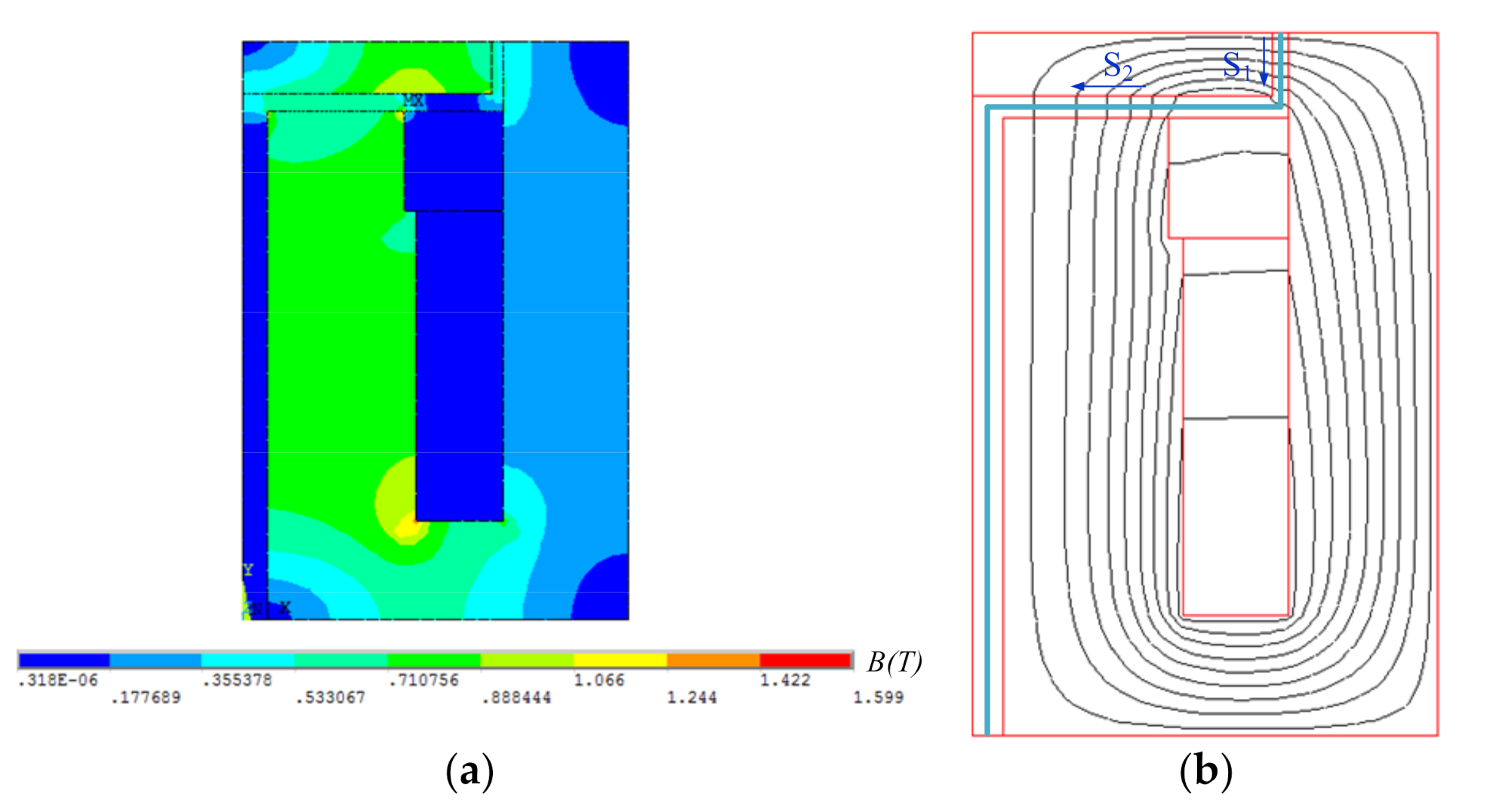
3. Magnetic Field Simulation of the Compact Annular-Radial-Orifice Flow MR Valve

3.1. Properties of the MR Fluid

In order to investigate the pressure drop performance and damping characteristics of the proposed MR valve, the values of the field yield stress of annular damping gap (τy,a) and radial damping gap (τy,r) need to be determined. The MRF-J01T MR fluid was selected in this paper, which was produced by Chongqing Institute of Materials in China [24]. The relationship between magnetic flux densities B and yield stress τy is nonlinear. Generally, the field yield stress can be determined by polynomial approximation, as follows:
τ y , a = a 3 × B M R , a 3 + a 2 × B M R , a 2 + a 1 × B M R , a + a 0
τ y , r = a 3 × B M R , r 3 + a 2 × B M R , r 2 + a 1 × B M R , r + a 0
where a0, a1, a2, and a3 are fitted by the least square method, indicating the polynomial coefficients of the shear yield stress at the damping gap varying with the magnetic flux densities and a0 = 0.018 kPa, a1 = −48.46 kPa/T, a2 = 865.39 kPa/T2, a3 = −984.27 kPa/T3.

3.2. Finite Element Analysis of the Proposed MR Valve

Considering the calculation scale and accuracy, the electromagnetic circuit was analyzed by using the axisymmetric two-dimensional (2D) finite element model shown in Figure 4. In the simulation, neglecting the influence of the end cover, flow guided plate and other structures on the magnetic field, top-down modeling approach is adopted, and the two dimensional simplified simulation geometry model of the proposed MR valve is shown in Figure 4a. A level 1 smartsize intelligent mesh division and a quadrilateral mesh structure element are chosen and the magnetic flux line parallel boundary without magnetic leakage is also applied. In the figure, the division of distinctive colors represents the material with different attributes. The annular damping gap was fixed to 1.0 mm, while the radial damping gap were set to 0.5 mm, 0.8 mm, 1.0 mm, and 1.5 mm, respectively. The current density in the excitation coil was set to 2.51 A/mm2 under the current applied to the excitation coil was equal to 2 A. The diameter of excitation coil conductor was selected as 0.6 mm, and the number of turns was 400. The solid model was meshed by quadrilateral elements, with the total number of elements of 1629 and the total number of nodes of 5036, which was displayed in Figure 4b.
The distribution of magnetic flux density and magnetic flux line in the two-dimensional finite element model are shown in Figure 5a,b, respectively. Observing Figure 5a, the color distribution of the regions at the radial damping gap and the annular damping gap are uniform and the colors of the regions at the radial damping gap is slightly different with that at the annular damping gap, which indicates that the magnetic flux density distribution of the two regions are uniform, and the magnetic flux densities at the radial damping gap is larger than those at the annular damping gap, but the difference between the two is not large. In order to more explicitly comprehend the distribution of magnetic flux density at each liquid flow gaps, two paths S1 and S2 are defined, among which the path S1 is annular fluid flow gap and the path S2 is radial fluid flow gap. The position of the two defined paths is presented in Figure 5b.
The variation of the magnetic flux density along the flow paths with the applied current of 2 A is shown in Figure 6. Observing Figure 6, the magnetic flux density is mainly concentrated in the annular and radial damping gaps, while the magnetic flux density at the small orifice flow channel is basically 0 T and it is due to the fact that there is almost no magnetic line passing through the small orifice flow channel. The magnetic flux density of the radial damping gap is greater than that of the annular damping gap when the radial damping gap is fixed, but there is little difference between the two gaps, which indicates that the advantages of the proposed MR valve with high magnetic field utilization.

3.3. Simulation Analysis of Pressure Drop

Figure 7 imply that the variation of the simulated pressure drop with different applied currents at the radial damping gap of 1.5 mm. The total pressure drop and the corresponding pressure drop of each channel significantly improve with the increment of the applied current, but the pressure drop of the small orifice flow channel remains unchanged. Under the applied current of 2 A, Figure 7b displays the percentage contribution of each region to pressure drop of the MR valve is 53.19%, 41.35%, and 5.46%, respectively.
Figure 8 illustrates the variation curves of the total pressure drop, the shear stress of the annular damping gap, and the shear stress of the radial damping gap with different applied currents at the radial damping gap of 1.5 mm. It can be obviously found from Figure 8 that the shear stress at the radial damping gap and the annular damping gap reaches saturation at the same time under the input current of 1.9 A, which the corresponding total pressure drop of the MR valve also reaches the maximum, and the maximum total pressure drop is about 1.434 MPa.

4. Experimental Analysis of the Compact Annular-Radial-Orifice Flow MR Valve

4.1. Prototyping of the Proposed MR Valve

Figure 9 shows the prototyping of the proposed MR valve, and Table 1 summarizes the primary valve parameters.

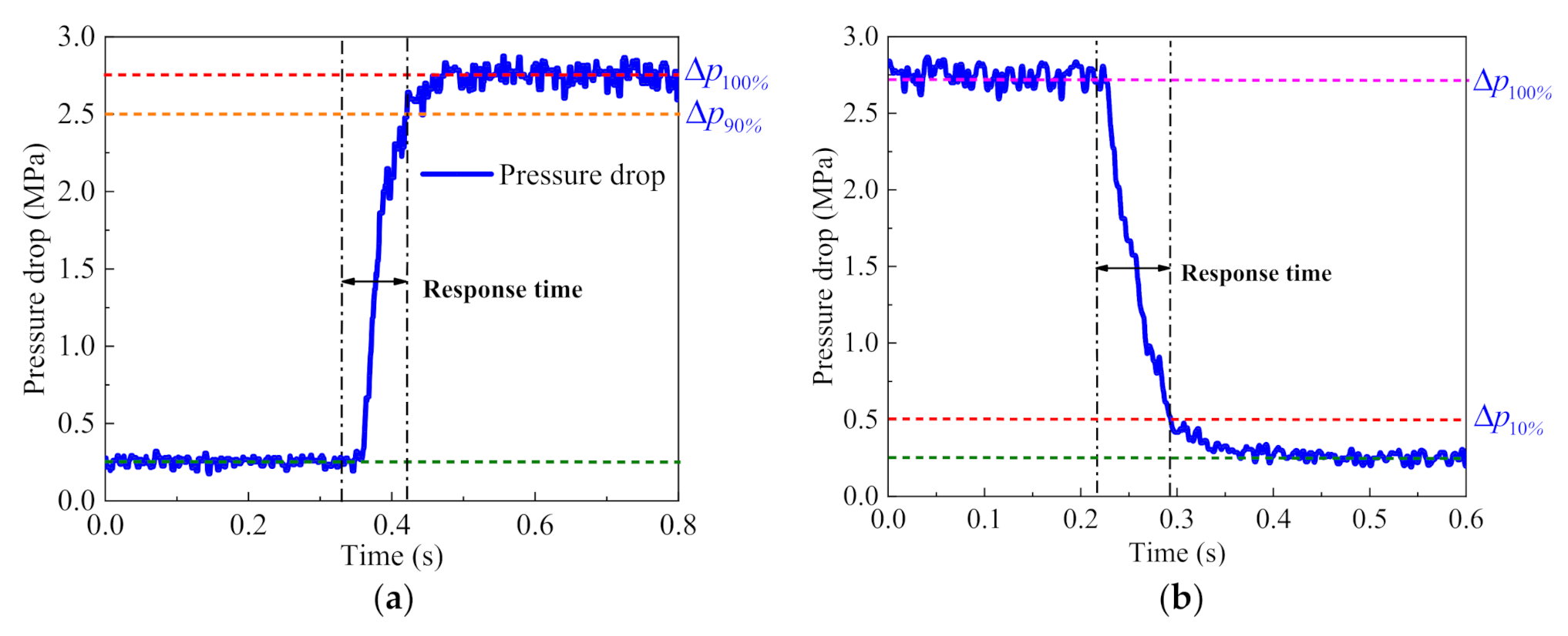
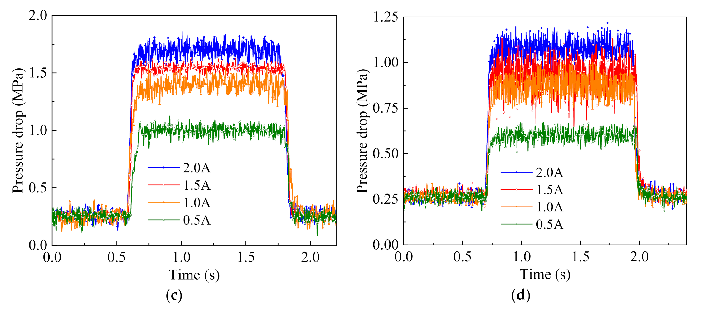
4.2. Experimental Analysis of Pressure Drop Performance and Response Characteristic

In order to investigate the pressure drop performance and response characteristic of the proposed MR valve, an experimental test rig is built up that is shown schematically in Figure 10. The test rig consists of gear pump, relief valve, DC power supply, and pressure sensor and data acquisition card. The motor driven gear pump is used as a power unit and can transport the MR fluid to the proposed MR valve. The pressure sensor I and the pressure sensor II are adopted to measure the inlet pressure and the outlet pressure of the proposed MR valve, respectively. The relief valve I is used as a safety valve to protect the hydraulic system, and the relief valve II is used as a counterbalance valve. DC power supply I is applied to supply the power for the excitation coil of the MR valve, DC power supply II is applied to supply the power for the two pressure sensors. The data acquisition card (DAQ) is adopted to acquire the data of the pressures of the system, and the host computer is used to real time monitor the relevant test parameters of the hydraulic system.
The motor model is Y280M2-4, the speed is 1390 r/min, and the power is 0.75 kW. The gear pump is CBW-B4 type with working pressure of 6.3 MPa, rotating speed of 1450 r/min and flow rate of 4 L/min. The relief valve model is P-B25B, the use pressure is 6.3 MPa, and the flow rate is 25 L/min. The pressure sensor is HQ-316 type, the measuring range is 0~4 MPa, and the output current is 4–20 mA. The model of acquisition card is NextKit Nano.
Figure 11 shows the experimental results of the pressure drop with the applied current at four different radial gaps. Observing Figure 11, the experimental pressure drop of the MR valve significantly enhances with the decrease of the radial damping gap at the same applied current. In addition, the experimental pressure drop also enhances with the increase of applied current. The maximum pressure drop at radial damping gap of 0.5 mm with current input of 2.0 A can reach about 2.67 MPa.
The response time plays a decisive role in the efficiency of the overall system, so it is of great significance to test the response time of the proposed MR valve in the test system [25,26]. In this dynamic performance test system, different control currents would generate different experimental pressure drop, and might lead to its different response characteristics. Here, the effect of radial damping gap on the response characteristics of the proposed MR valve was investigated by opening and closing the power supply with different current amplitudes. In order to investigate the response characteristics of the rise and fall of the MR valve, a square wave control signal was applied to the circuit. In this article, the rising response time (trise) was defined to be the transition time when the pressure drop of the MR valve from the initial value to the stable state value of accomplish the maximum pressure drop of 90% after the current connection, and the falling response time (tfall) was the transition time lost to the maximum pressure drop of 10%, as shown in Figure 12.
The dynamic response characteristic of the proposed MR valve with four different radial damping gaps was experimentally tested under the DC power supply I. The experimental results were revealed in Figure 13 and Table 2. Observing Figure 13, the applied current was varied from 0 A to 2 A in the steps of 0.5 A at constant radial damping gap, the rising response time displays an increasing trend, and the change trend of the falling response time was also obvious. According to Table 2, when the radial damping gap was fixed at 0.5 mm, the rising response time of the MR valve was 119 ms at 0.5 A, while increases by 47.90% to 176 ms at 2 A. Nevertheless, the corresponding falling response time increased by less than 7% from 129 ms at 0.5 A to 138 ms at 2 A, and has clearly demonstrated that the magnitude of the loading current had little effect on the falling response time of the MR valve.
Figure 14 shows comparison of the rising and falling response time curves for the proposed MR valve with four different radial damping gaps, Table 2 shows the corresponding response times. As observed, under the same current excitation of 2 A, with the enhancement of radial damping gap, the rising response time of the proposed MR valve at each radial damping gap were 176 ms, 153 ms, 119 ms, and 85 ms, respectively. The falling response time was 138 ms, 133 ms, 128 ms, and 89 ms, respectively. In other words, the response time of the MR valve gradually increased from 85 ms and 89 ms with the radial damping gap of 1.5 mm to about 176 ms and 138 ms with the radial damping gap of 0.5 mm. It can be concluded that the proposed MR valve with the radial damping gap of 1.5 mm has shorter response time. In addition, under the same applied current, the increment of response time of the proposed MR valve was greater with the diminution of radial damping gap.
Consequently, when the applied current was 1.5 A and the radial damping gap were set to 0.5, 0.8, 1.0, and 1.5 mm, the average response times of the proposed MR valve were 143 ms, 118 ms, 114 ms, and 77 ms, respectively. Although the response times of the MR fluid was about several milliseconds, the measured response time of the proposed MR valve in the response test rig was still longer. This was mainly due to the experimental conditions, once the current step signal was activated by turn on or off the power supply, the pressure drop of the proposed MR valve would change transiently, so the larger interaction energy in ferromagnetic particles of the MR fluid needs more time to occur step current or to recover to zero current state. Moreover, there are the coils and magnetic materials in the electronic circuit of the test system, and there are phenomena of coil inductance and eddy current in the magnetic circuit, which significantly prolong the response time of the proposed MR valve under the different control currents.

5. Experimental Analysis of the Valve Controlled Cylinder System

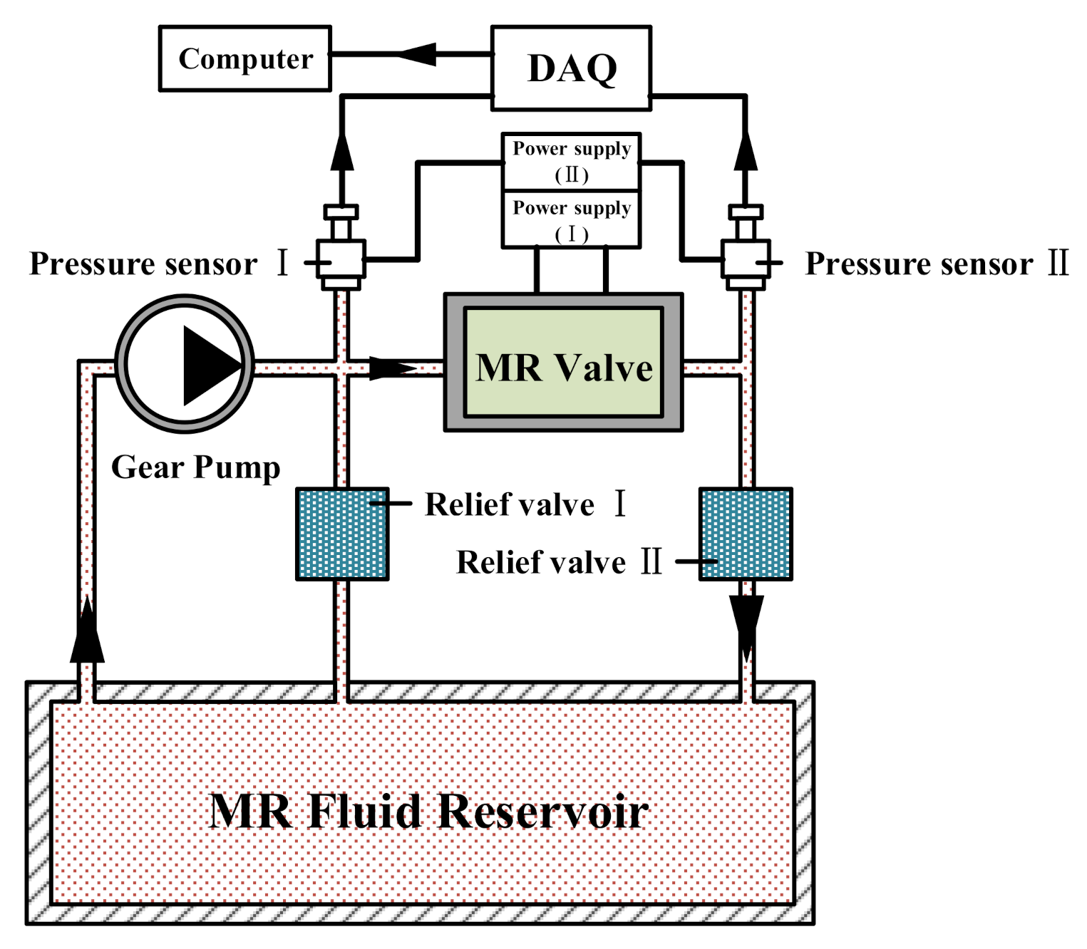
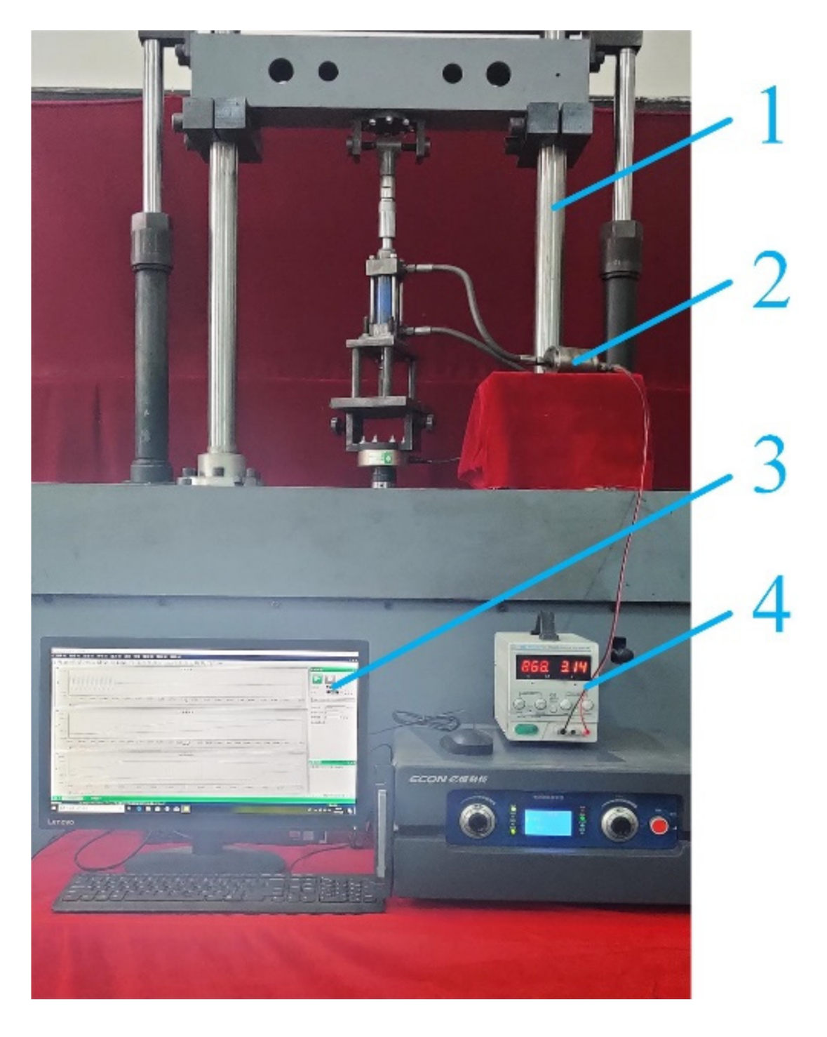
5.1. Test System of the Proposed MR Valve Controlled Cylinder System

In order to further explore the application of the proposed MR valve in industry, the annular-radial-orifice flow MR valve controlled cylinder system was proposed and set up, which were mainly composed of the double rod hydraulic cylinder, the hydraulic pipe, and the proposed MR valve. The working principle and prototype of the MR valve controlled cylinder system were displayed in Figure 15.
Since the effective working area of the double rod piston hydraulic cylinder in the left and right cavities is equal, its output damping force and output velocity in two directions are equal. According to Figure 15a, the output velocity v of the double rod piston hydraulic cylinder in the left and right directions can be expressed as
v = q A = 4 q π D 2 d 2
where q is the flow rate through the MR valve, A is the piston effective areas, D is diameter of the piston, and d is diameter of the piston rod.
Due to the relative lubrication between the piston head and the hydraulic cylinder, the friction coefficient is very small. In the meantime, the friction force between the cylinder and the piston head is much larger than that between the cylinder and the piston rod. Hence, the friction force can be ignored, and the output damping force F of the system can be calculated by
F = p 1 p 2 A = π 4 D 2 d 2 p 1 p 2
where p1 is the inlet chamber pressure, and p2 is the return chamber pressure.
Whether the hydraulic cylinder piston moves left or right, the inlet pressure p1 and the return pressure p2 are provided by the inlet and outlet pressure of the proposed MR valve, respectively. Therefore, the inlet and output pressure of the MR valve controlled cylinder system is the pressure drop at both ends of the MR valve, which can be expressed as
Δ p = p 1 p 2
The experimental test rig for the dynamic performance of the valve controlled cylinder system was set up, as shown in Figure 16. In this test rig, the fixture on the damper test system is used to fix the lower end of the double rod hydraulic cylinder, and the displacement sensor and force sensor are installed in the damper test system to connect the upper end of the double-rod hydraulic cylinder. The DC power supply is applied to the control current in the excitation coil, and the damper test system can provide different sinusoidal vibration excitation for the double rod hydraulic cylinder. Finally, the data of damping force and displacement can be transmitted to the host computer in real time through the data acquisition card.

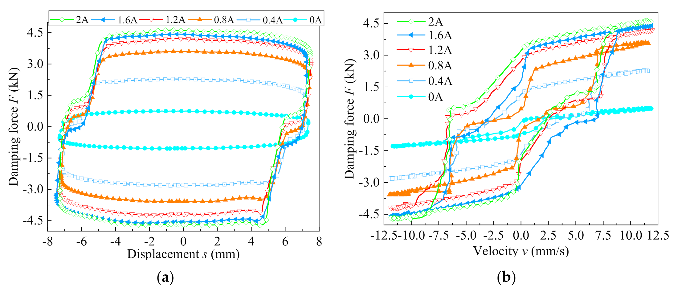
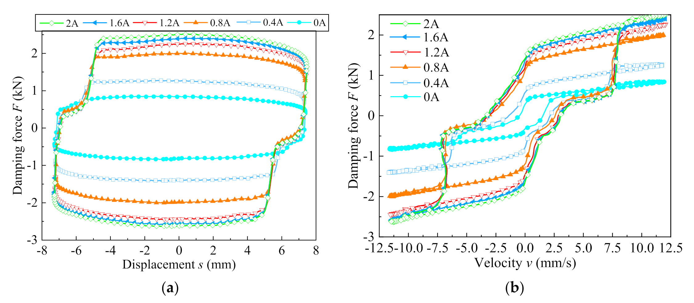
5.2. Dynamic Performance of the Valve Controlled Cylinder System at the Radial Gap of 0.5 mm

In the experiment, the power knob was manually adjusted to provide different currents for the proposed MR valve controlled cylinder system, so as to obtain the required output damping force. Firstly, the MR valve with annular damping gap of 1.0 mm and radial damping gap of 0.5 mm were selected for the experimental test. Figure 17a,b show the experimental results of the relationship between the damping force and the piston displacement, and the damping force and piston velocity, respectively, under a sine excitation of amplitude of 7.5 mm and frequency of 0.25 Hz. Observing Figure 17, the damping force of the MR valve controlled cylinder system exhibits clearly enhancement with the augmentation of the applied current. Furthermore, the damping force increase amplitude slower when the applied current was larger than 1.2 A, which indicates that the magnetic flux density and shear stress of the MR fluid reach saturation, and the pressure drop at both ends of the proposed MR valve gradually reaches the maximum value, the maximum damping force of the MR valve controlled cylinder system can reach about 4.72 kN at the applied current of 2 A. The curve presented in Figure 17a has some distortion and missing in the upper left and lower right parts. This phenomenon may be due to the fact that a part of the air was mixed into the MR fluid when filling the system, resulting in an empty stroke when the piston moves, and the piston cannot obtain the damping force transmitted from the MR fluid, which makes a small part of the curve missing.
Figure 18a illustrates that the variation of the damping force and the displacement for the MR valve controlled cylinder system with different amplitudes at current of 0.8 A and frequency of 0.25 Hz. According to Figure 18a, the damping force changes slowly with the augment of displacement under the same amplitude. However, the output damping force of the MR valve controlled cylinder system increases significantly with enhancement of the displacement when the amplitude increases from 5 mm to 10 mm. The maximum damping force of the MR valve controlled cylinder system can reach about 4 kN under the amplitude of 10 mm. The force-displacement curves of the MR valve controlled cylinder system with different vibration frequencies at 0.8 A current and 7.5 mm amplitude, as shown in Figure 18b. Observing Figure 18b, the damping force of valve controlled cylinder system gradually increases with the increase of the vibration frequency; the maximum output damping force can reach 4.7 kN under the vibration frequency of 1 Hz. Among them, the damping force increases with the increase of amplitude and frequency, which is mainly due to the increase of the flow velocity of the MR fluid in the valve controlled cylinder system, which increases the pressure drop at both ends of the MR valve, thus increasing the output damping force.

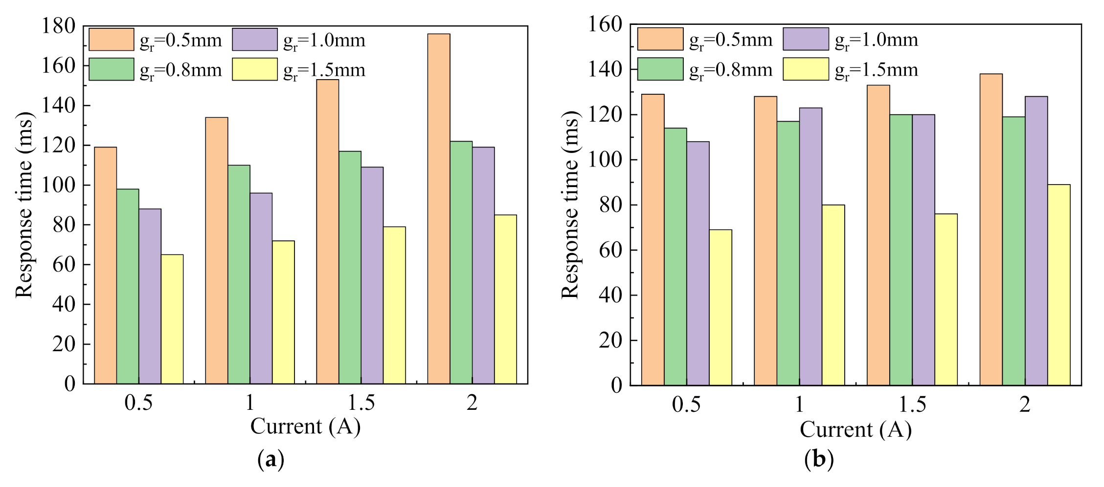
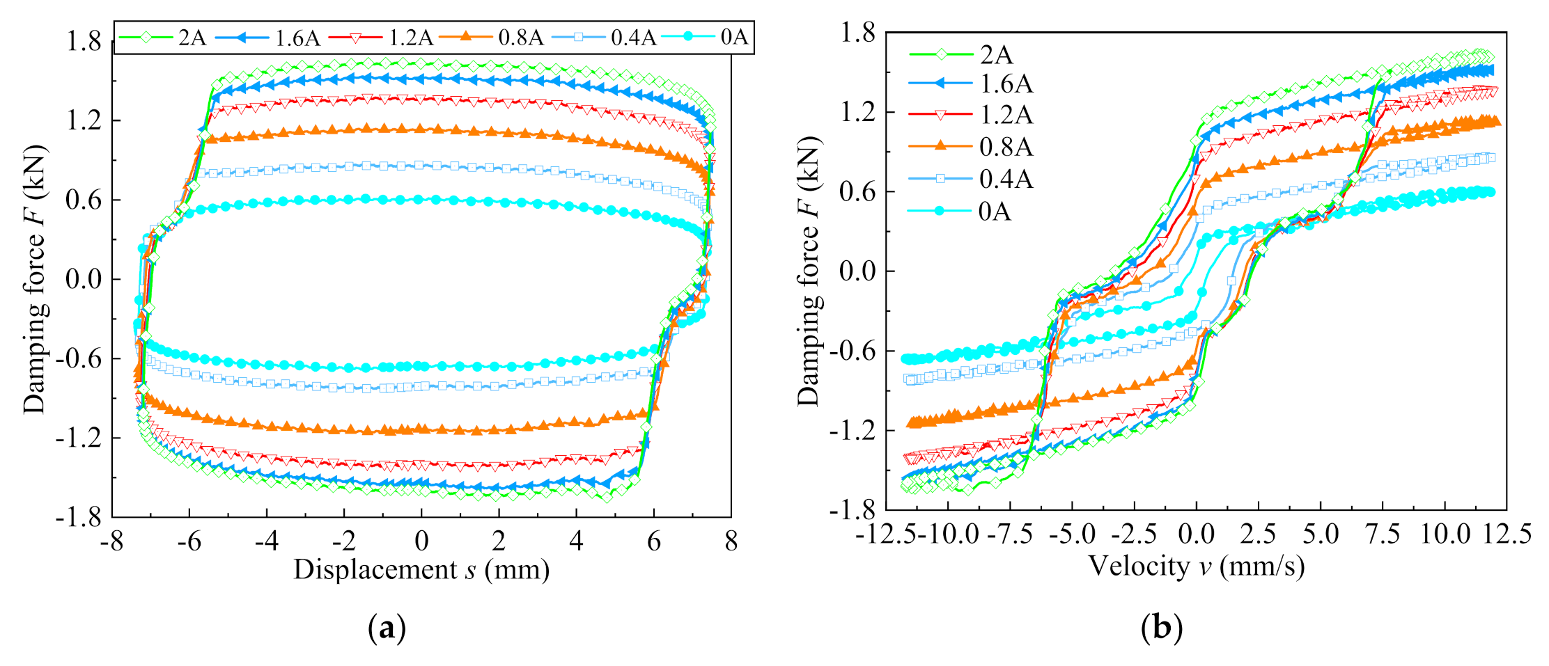
5.3. Dynamic Performance with Variable Radial Damping Gap

Figure 19 and Figure 20 display the dynamic performance variation of the valve-controlled cylinder system with different applied currents when the annular damping gap was fixed at 1.0 mm and the radial damping gap were 1.0 mm and 1.5 mm, respectively. In the experimental test, the amplitude and vibration frequency were fixed to 7.5 mm and 0.25 Hz, respectively, and the applied currents were set to 0 A, 0.4 A, 0.8 A, 1.2 A, 1.6 A, and 2.0 A, respectively. In Figure 19 and Figure 20, with the increase of applied current, the corresponding experimental damping force of the valve controlled cylinder increases accordingly under the fixed amplitude and frequency, and the increase amplitude of damping force decreases when the applied current exceeds 1.2 A. The experimental results manifest that the maximum damping force of the valve controlled cylinder system reaches about 2.68 kN at the radial damping gap of 1 mm and the current of 2 A, as well as the maximum damping force of the valve-controlled cylinder system reaches about 1.6 kN at the radial damping gap of 1.5 mm and the current of 2 A.
Figure 21 indicates that the dynamic variation of the damping gap and the displacement under four different radial damping gaps. The testing results demonstrate that the damping force of the MR valve controlled cylinder system decreases gradually with the damping gaps increases from 0.5 mm to 1.5 mm. According to Figure 21a, when the applied current was 1.2 A, the amplitude and frequency were set to 7.5 mm and 0.25 Hz, respectively, the corresponding maximum damping force was identified with the values of 4.24 kN and 1.4 kN associated with the radial damping gap of 0.5 mm and 1.5 mm, respectively. According to Figure 21b, when the amplitude was 10 mm, the current and frequency were set to 0.8 A and 0.25 Hz, respectively, the corresponding maximum damping force gently reaches 3.93 kN at the radial damping gap of 0.5 mm, and the maximum corresponding damping force was up to 1.24 kN at the radial damping gap of 1.5 mm. According to Figure 21c, when the frequency was 0.5 Hz, the current and amplitude were set to 0.8 A and 7.5 mm, respectively, the maximum corresponding damping force increased from 1.43 kN at the radial damping gap of 1.5 mm to 4 kN at the radial damping gap of 0.5 mm.
Figure 22 indicates the relationship between experimental damping force and current in the MR valve controlled cylinder systems with four different radial damping gaps. From Figure 22, the experimental damping force of the MR valve controlled cylinder system increases with enhances of applied current and the diminution of radial damping gap. Under the annular damping gap was fixed at 1.0 mm and the applied current of 2 A, the experimental damping force appears a peak of 4.72 kN at radial damping gap of 0.5 mm. Meanwhile, the corresponding maximum damping force also reach about 1.6 kN at radial damping gap of 1.5 mm.
Figure 23 depicts the dynamic variation of the experiment, simulation, and theory damping forces under different currents and variable radial gaps. It can be observed that the damping forces of the simulation, theory and experiment of the proposed MR valve controlled cylinder system increase correspondingly with the increase of applied current, and the variation trend of the damping force of the simulation, theory and experiment is concordant. The maximum damping forces of the simulation, theory, and experiment are 5.741 kN, 5.124 kN, and 4.72 kN, respectively, which are based on the annular damping gap of 1.0 mm, the radial damping gap of 0.5 mm, and the applied current of 2 A. Furthermore, the corresponding damping forces of simulation and theory are mostly larger than those experimental results at the different radial damping gaps. The possible reason is that the MR fluid flowing through the hydraulic pipe has a large linear loss in the experimental test, which will be a certain difference between the experiment value and the simulation and theory values. On the other hand, because the Bingham model does not consider the effect of fluid shear thickening in the magnetic field simulation, and under the effect of magnetic field, the iron powder particles of the MR fluid in the liquid flow channel are aggregated from single chain to columnar, so that the saturated shear stress in the simulation and theory are greater than that in the actual test. In addition, there is a certain degree of magnetic leakage in the magnetic field during the experiment, which will also lead to the low experimental results.

6. Conclusions

This paper designed and developed a compact annular-radial-orifice flow MR valve with variable radial damping gaps which consist of annular damping gap, radial damping gap, and small orifice flow channel in sequence. Simultaneously, the size of radial damping gap can be guaranteed by replacing the washers of different thickness. Additionally, the average magnetic flux density in annular, radial, and small-orifice flow channels were analyzed based on finite element methodology.
The pressure drop performance and response characteristics of the proposed MR valve with radial damping gaps of 0.5 mm, 0.8 mm, 1.0 mm, and 1.5 mm were investigated experimentally. The maximum experimental pressure drop up to 2.67 MPa at the radial damping gap of 0.5 mm and the applied current of 2.0 A. Moreover, in the rising state, the response time of the MR valve increases with increment of the applied current, but in the falling state, the applied current has little effect on the response time of the MR valve.
Experimental damping forces of the MR valve controlled cylinder systems with different radial damping gaps were tested on the dynamic test rig. Furthermore, dynamic performance of the MR valve was validated by a series of dynamic tests at different currents, amplitudes, and frequencies. The experimental result demonstrates that the corresponding experimental damping force of valve controlled cylinder system remarkably increases with decreases of the radial damping gaps, and when the radial damping gaps were 0.5 mm, 0.8 mm, 1.0 mm, and 1.5 mm and the applied current was 2 A, the output damping force of the valve controlled cylinder system reaches the maximum, and the corresponding maximum values were 4.72 kN, 2.89 kN, 2.68 kN, and 1.60 kN, respectively.
The proposed MR valve significantly improves its efficiency through compact design and variable radial damping gaps. The experimental result illustrates that different radial damping gaps correspond to different response characteristics and dynamic performance. Hence, the proposed MR valve can be used as a bypass valve for various vibration reduction applications.

Author Contributions

G.H. developed the compact annular-radial-orifice flow MR valve and revised the paper; F.Z. conducted experimental research and wrote the first draft. M.L. and L.Y. conducted theoretical analysis and set up the experimental test rig. All authors have read and agreed to the published version of the manuscript.

Funding

This research was funded by the National Natural Science Foundation of China, grant number 51765016.

Conflicts of Interest

The authors declare no conflict of interest.

References

  1. Kumar, J.S.; Paul, P.S.; Raghunathan, G.; Alex, D.G. A review of challenges and solutions in the preparation and use of magnetorheological fluids. Int. J. Mech. Mater. 2019, 14, 1–18. [Google Scholar] [CrossRef]
  2. Zhang, Y.; Li, D.; Cui, H.; Yang, J. A new modified model for the rheological properties of magnetorheological fluids based on different magnetic field. J. Magn. Magn. Mater. 2020, 500, 166377. [Google Scholar] [CrossRef]
  3. Ai, H.X.; Wang, D.H.; Liao, W.H. Design and modeling of a magnetorheological valve with both annular and radial flow paths. J. Intell. Mater. Syst. Struct. 2006, 17, 328–334. [Google Scholar] [CrossRef]
  4. Hu, G.L.; Zhong, F.; Zhang, H.Y.; Ding, R.Q. Structure optimization and performance analysis of a multiple radial magnetorheological valve. J. Beijing Inst. Technol. 2017, 26, 458–467. [Google Scholar]
  5. Idris, M.H.; Imaduddin, F.; Mazlan, S.A.; Choi, S.B. A concentric design of a bypass magnetorheological fluid damper with a serpentine flux valve. Actuators 2020, 9, 16. [Google Scholar] [CrossRef] [Green Version]
  6. Hu, G.L.; Li, L.S.; Liu, H.; Liu, F.S. Effects of winding cylinder materials on dynamic performances of a new mr damper. IEEE Access 2020, 8, 87829–87841. [Google Scholar] [CrossRef]
  7. Bai, X.X.; Cai, F.; Chen, P. Resistor-capacitor (RC) operator-based hysteresis model for magnetorheological (MR) dampers. Mech. Syst. Signal Process. 2019, 117, 157–169. [Google Scholar] [CrossRef]
  8. Hu, G.L.; Wu, L.F.; Li, L.S.; Yu, L.F. Performance analysis of rotary magnetorheological brake with multiple fluid flow channels. IEEE Access 2020, 8, 173323–173335. [Google Scholar] [CrossRef]
  9. Sun, S.S.; Ning, D.H.; Yang, J. Development of an MR seat suspension with self-powered generation capability. J. Smart Mater. Struct. 2017, 26, 085025. [Google Scholar] [CrossRef]
  10. Bai, X.; Hu, W.; Wereley, N.M. Magnetorheological damper utilizing an inner bypass for ground vehicle suspensions. IEEE Trans. Magn. 2013, 4, 3422–3425. [Google Scholar] [CrossRef]
  11. Lee, T.H.; Shin, S.U.; Cha, S.W.; Choi, S.B. Fine position control of a vehicle maintenance lift system using a hydraulic unit activated by magnetorheological valves. J. Intell. Mater. Syst. Struct. 2019, 30, 896–907. [Google Scholar] [CrossRef]
  12. Ntella, S.L.; Duong, M.T.; Civet, Y.; Pataky, Z.; Perriard, Y. Design optimization of miniature magnetorheological valves with self-sensing capabilities used for a wearable medical application. In Proceedings of the 2020 IEEE/ASME International Conference on Advanced Intelligent Mechatronics, Boston, MA, USA, 6–9 July 2020; pp. 409–414. [Google Scholar]
  13. Grunwald, A.; Olabi, A.G. Design of magneto-rheological (MR) valve. Sens. Actuators A Phys. 2008, 148, 211–223. [Google Scholar] [CrossRef] [Green Version]
  14. Hu, G.L.; Long, M.; Huang, M.; Li, W.H. Design, Analysis, prototyping, and experimental evaluation of an efficient double coil magnetorheological valve. Adv. Mech. Eng. 2014, 6, 403410. [Google Scholar] [CrossRef] [Green Version]
  15. Sahin, H. Theoretical and Experimental Studies of Magnetorheological (MR) Fluids and MR Greases/Gels from Rheology to System Application; University of Nevada: Reno, NV, USA, 2008. [Google Scholar]
  16. Imaduddin, F.; Mazlan, S.A.; Zamzuri, H.; Yazid, I.I.M. Design and performance analysis of a compact magnetorheological valve with multiple annular and radial gaps. J. Intell. Mater. Syst. Struct. 2015, 26, 1038–1049. [Google Scholar] [CrossRef]
  17. Hu, G.L.; Long, M.; Yu, L.F.; Li, W.H. Design and performance evaluation of a novel magnetorheological valve with a tunable resistance gap. Smart Mater. Struct. 2014, 23, 127001. [Google Scholar] [CrossRef]
  18. Shou, M.j.; Liao, C.R.; Zhang, H.H.; Xie, L. A design methodology based on full dynamic model for magnetorheological energy absorber equipped with disc springs. Smart Mater. Struct. 2019, 28, 065020. [Google Scholar] [CrossRef]
  19. Armin, H.; Ramin, S.; Ebrahim, E. Design optimization of magnetorheological fluid valves using response surface method. J. Intell. Mater. Syst. Struct. 2013, 25, 1352–1371. [Google Scholar]
  20. Zhang, X.J.; Yang, Y.; Guo, K.H.; Sun, S.L.; He, G.J.; Li, Z.H. Methodology on a novel magnetorheological valve controlled damper synthesis design. Smart Mater. Struct. 2020, 29, 045006. [Google Scholar] [CrossRef]
  21. Manjeet, K.; Bhagyarajan, A.; Sujatha, C. Regression models for magnetic flux density using DoE techniques and geometric optimization of MR valve. Smart Mater. Struct. 2019, 28, 075008. [Google Scholar]
  22. Hu, G.L.; Liao, M.K.; Li, W.H. Analysis of a compact annular-radial-orifice flow magnetorheological valve and evaluation of its performance. J. Intell. Mater. Syst. Struct. 2017, 28, 1322–1333. [Google Scholar] [CrossRef] [Green Version]
  23. Hu, G.L.; Zhang, J.W.; Liao, M.K.; Ding, R.Q. The effect of radial resistance gap on the pressure drop of a compact annular-radial-orifice flow magnetorheological valve. J. Beijing Inst. Technol. 2018, 27, 535–546. [Google Scholar]
  24. Hu, G.L.; Zhang, J.W.; Zhong, F.; Yu, L.F. Performance evaluation of an improved radial magnetorheological valve and its application in the valve controlled cylinder system. Smart Mater. Struct. 2019, 28, 047003. [Google Scholar] [CrossRef]
  25. Sahin, H.; Gordaninejad, F.; Wang, X.; Liu, Y.M. Response time of magnetorheological fluids and magnetorheological valves under various flow conditions. J. Intell. Mater. Syst. Struct. 2012, 23, 949–957. [Google Scholar] [CrossRef]
  26. Yoon, D.S.; Park, Y.J.; Choi, S.B. An eddy current effect on the response time of a magnetorheological damper: Analysis and experimental validation. Mech. Syst. Signal Process. 2019, 127, 136–158. [Google Scholar] [CrossRef]
1
Thickness of positioning plate td
Figure 1. Schematic configuration of the annular-radial-orifice flow MR valve: 1. Left end cover; 2. Flow guided plate; 3. Screw; 4. Magnetic disk; 5. Washer; 6. Positioning plate; 7. Valve body; 8. Excitation coil; 9. Valve spool; 10. Right end cover.
Actuators 10 00104 g001
Figure 2. The simplified magnetic circuit of the annular-radial-orifice flow MR valve.
Actuators 10 00104 g002
Figure 3. Pressure drop distribution of the proposed MR valve.
Actuators 10 00104 g003
Figure 4. 2D finite element model of the MR valve: (a) geometric model, (b) meshed model.
Actuators 10 00104 g004
Figure 5. Simulation results of the proposed MR valve: (a) magnetic flux density contour, (b) magnetic flux line distribution.
Actuators 10 00104 g005
Figure 6. Magnetic flux density along the defined paths for 2A current with variable radial damping gap.
Actuators 10 00104 g006
Figure 7. Estimation of simulated pressure drop of the proposed MR valve: (a) pressure drop variations from each region, (b) percentage of pressure drop from each region.
Actuators 10 00104 g007
Figure 8. Variation curve of the shear stress and total pressure drop with the applied current.
Actuators 10 00104 g008
Figure 9. Photograph of the annular-radial-orifice flow MR valve: (a) valve parts, (b) valve assembly.
Actuators 10 00104 g009
Figure 10. Schematic diagram for experimental setup of the proposed MR valve.
Actuators 10 00104 g010
Figure 11. Variation of pressure drop with current under four radial gaps.
Actuators 10 00104 g011
Figure 12. Definition of response time of the MR valve: (a) rising response time, (b) falling response time.
Actuators 10 00104 g012
Figure 13. Response time of the MR valve under different radial damping gaps: (a) 0.5 mm, (b) 0.8 mm, (c) 1.0 mm, (d) 1.5 mm.
Actuators 10 00104 g013aActuators 10 00104 g013b
Figure 14. Comparison of response time of the MR valve under different radial damping gaps: (a) rising response time, (b) falling response time.
Actuators 10 00104 g014
Figure 15. Working principle diagram and prototype of the MR valve controlled cylinder system: (a) working principle diagram, (b) prototype.
Actuators 10 00104 g015
Figure 16. Experimental test rig of the proposed MR valve controlled cylinder system: 1. Damper test system; 2. Annular-radial-orifice flow MR valve controlled cylinder system; 3. Host computer; 4.DC power supply.
Actuators 10 00104 g016
Figure 17. Damping performance of valve controlled cylinder system with radial damping gap of 0.5 mm: (a) force versus displacement, (b) force versus velocity.
Actuators 10 00104 g017
Figure 18. Damping force versus displacement: (a) under variation amplitudes, (b) under variation frequencies.
Actuators 10 00104 g018
Figure 19. Damping performance of valve controlled cylinder system with radial damping gap of 1.0 mm: (a) force versus displacement, (b) force versus velocity.
Actuators 10 00104 g019
Figure 20. Damping performance of valve controlled cylinder system with radial damping gap of 1.5 mm: (a) force versus displacement, (b) force versus velocity.
Actuators 10 00104 g020
Figure 21. Comparison of damping force of the MR valve controlled cylinder system with different damping gaps: (a) applied current of 1.2 A, (b) amplitude of 10 mm, (c) vibration frequency of 0.5 Hz.
Actuators 10 00104 g021
Figure 22. The experimental damping force versus the current under different radial damping gaps.
Actuators 10 00104 g022
Figure 23. Dynamic variation of experiment, simulation, and theory damping forces under different currents and variable radial gaps: (a) simulation versus experiment, (b) theory versus experiment.
Actuators 10 00104 g023
Table 1. Relevant dimension parameters of the proposed MR valve.
ParametersValues (mm)
Thickness of annular gap ga1
Thickness of radial gap gr0.5~1.5
Valve body thickness th10
MR valve radius R31
Valve spool length L41
Thickness of winding groove Wc7
Orifice radius R02
Radius of left valve spool with screw thread Rd13
Radius of left valve spool without screw thread Rc14
Thickness of the right of valve spool tc8
Annular gap length La4.2
Radial gap length Lr11
Thickness of positioning plate td8
Table 2. Response characteristic of the annular-radial-orifice flow MR valve.
Current(A)0.5 mm0.8 mm1.0 mm1.5 mm
trisetfalltrisetfalltrisetfalltrisetfall
0.5119 ms129 ms98 ms114 ms88 ms108 ms65 ms69 ms
1.0134 ms128 ms110 ms117 ms96 ms123 ms72 ms80 ms
1.5153 ms133 ms117 ms120 ms109 ms120 ms79 ms76 ms
2.0176 ms138 ms122 ms119 ms119 ms128 ms85 ms89 ms
Publisher’s Note: MDPI stays neutral with regard to jurisdictional claims in published maps and institutional affiliations.

