Article

Direct Drive Servovalves Actuated by Amplified Piezo-Stacks: Assessment through a Detailed Numerical Analysis †

1
Department of Mechanics, Mathematics and Management (DMMM), Polytechnic University of Bari, 70121 Bari, Italy
2
Centre for Power Transmission and Motion Control (PTMC), University of Bath, Bath BA2 7AY, UK
*
Author to whom correspondence should be addressed.
This paper is an extended version of “Tamburrano, P., De Palma, P., Plummer, A. R., Distaso, E., & Amirante, R. (2020). Feasibility study of using amplified piezo-stack actuators for the actuation of direct drive servovalves. In Proceedings of the 75th National ATI Congress—#7 Clean Energy for All (ATI 2020), Rome, Italy, 15–16 September 2020”.
Submission received: 17 May 2021 / Revised: 2 July 2021 / Accepted: 5 July 2021 / Published: 7 July 2021
(This article belongs to the Special Issue Recent Advances on Servovalves)

Abstract

:
This paper presents a feasibility study using commercially available amplified piezo-stacks for the direct actuation of four-way three-position (4/3) direct drive servovalves. The prospect of using amplified piezo-stacks in place of linear force motors is very attractive by virtue of their fast response speed and low weight. Piezo-stacks equipped with mechanical amplification systems can give levels of displacement suitable for this application. A very effective amplification system has recently been produced by some manufacturers and is based on a temperature-independent diamond structure. This paper details simulations of a 4/3 servovalve directly actuated by such a piezoelectric actuator with a diamond structure. To this end, well-established equations, implemented in Simulink by means of the libraries of Simscape Fluids, are used. The proposed architecture shows simplicity of construction; in addition, very good step response speed and frequency response are predicted by the simulations.

1. Introduction

Electro-hydraulic servovalves provide very accurate flow control and a very fast response in hydraulic systems demanding high performance levels [1,2]. There are mainly two types of commercially available servovalves: the two-stage type, in which a torque motor is used to amplify the hydraulic power by means of a pilot stage, and the direct-drive type, in which the spool is directly driven by a linear force motor. The former can have mechanical or electrical feedback for the control of the spool position; the latter usually has only electrical feedback [1]. The former is the most common architecture, since a two-stage architecture provides several benefits, such as very high actuation forces and low weight in addition to a fast response speed, thus being very appropriate for aeronautical applications. However, it has a few shortcomings, such as high manufacturing costs, complex structure, high leakage in the pilot stage [1], and significant vibration of the torque motor [3]. The pilot stages are also subject to intense cavitation, and current research studies aim at tackling this issue by proposing novel solutions and investigations [4,5,6,7]. Electrical faults in the pilot stage may also occur, including permanent magnet demagnetization, aging of the electrical components, coil faults, amplifier faults, and sensor faults [8].
Direct-drive servovalves are produced by companies such as Moog [9,10], the world-leading manufacturer of servovalves, using linear force motors (LFMs) to directly move the spool inside its bushing sleeve. LFMs, employing rare earth magnets, have larger actuation forces, better linearity and a faster dynamic response than proportional solenoids, thus having better performance and wider operation ranges [11].
A direct drive architecture has the disadvantage of having lower actuation forces than two-stage servovalves; hence, it has lower chip shear capability and a lower response speed [1]. In addition, an LFM, being approximately the same size as the main stage, is much larger and heavier than a torque motor. Compared to a two-stage servovalve, a direct drive servovalve is therefore less convenient for some applications, such as aircraft, where the actuation forces and weight are important factors. Instead, for those industrial applications where these factors are less important, a direct drive servovalve is an interesting architecture, especially in terms of simplicity of construction, in contrast to the complexity of pilot stages, which have many finely toleranced parts, some of them needing to be assembled manually [1].
This paper investigates whether a direct drive servovalve can be actuated by piezo-electric actuators (PEAs) in place of linear force motors. A PEA is a device based on the piezoelectric effect, namely, when an electric field is applied to a piezoceramic material, actuation force and displacement are generated. The excellent characteristics of PEAs, such as simple designs, reduced moving parts, high reliability and fast response, make them useful in several industrial applications [12]. The application of PEAs for the actuation of valves can allow the settling time to be minimized, as shown in [13], in which a new microvalve design was actuated by a piezoelectric bending cantilever.
Therefore, as far as the actuation of servovalves is concerned, the use of PEAs instead of electromagnetic actuators could lead to faster response time; in addition, lower energy consumption in the stationary state, smaller mass in motion, and simplification of the mechanical transmission can be achieved [14]. An issue could be hysteresis, which is quite significant in piezo-electric actuators; however, effective compensation techniques already exist in the literature [15], and closed-loop control can be used to reduce the effect of hysteresis.
Commercially available PEAs are rectangular and ring benders, piezo-stacks and amplified piezo-stacks [14]. Ring benders and rectangular benders were demonstrated to be suitable for the actuation of the pilot stages of servovalves [16,17,18,19]. A novel two-stage architecture employing two ring benders was studied by us in references [20,21], and its feasibility was assessed using a detailed Simulink model of the hydraulic, mechanical and electrical parts.
Those studies proved that ring benders and rectangular benders are suitable for the actuation of the pilot stages of servovalves; however, they are not appropriate for the direct actuation of a main spool due to their low displacement and low actuation forces.
Piezo-stacks are different from ring benders and rectangular benders, being composed of many piezoelectric ceramic layers stacked to form a long actuator. The overall elongation is given by the sum of the contributions of all layers [22]. A very interesting paper testing a throttle valve prototype controlled by piezoelectric stacks can be found in [23].
There are more examples of applications of piezo-stacks for the direct actuation of servovalves [24], but the main disadvantage is given by the large dimensions of the piezo-stacks needed for this purpose. Indeed, as a rough estimate, a piezo-stack that is 15 cm long can produce a maximum free stroke of only 240 μm in one direction [14]; therefore, to obtain a displacement of 500 μm in one direction, a very large piezo-stack (about 30 cm long) is needed.
An amplified piezo-stack actuator allows for higher displacement to be achieved compared to a piezo stack. It is composed of a piezo-stack and an amplification system which is adopted to increase the displacement of the piezo-stack [14]. By virtue of the increased displacement, the direct actuation of a main spool is feasible. In the literature, there are two studies proposing servo-valves directly driven by amplified piezo-stacks [25,26]. In both cases, the mechanical amplifier is based on a lever mechanism. This valve configuration, despite providing a limited maximum flow rate (around 8 L/min for an inlet pressure of 40 bar [26]), shows that the concept is viable.
The idea here investigated thoroughly consists in using, in place of linear force motors, commercially available amplified piezo-stacks having diamond amplification mechanisms for the direct actuation of servovalves, in order to exploit the advantages that such amplified piezo stacks can provide, such as fast response and low weight. This idea was presented in [27], where a preliminary feasibility study was performed using a simplified Simulink model in order to predict simple open-loop test tests. In this paper, a more complete assessment is performed using a more detailed Simulink model, which is now able to simulate hysteresis and to simulate closed-loop control. In addition to more open-loop step tests, the effects of using different amplifiers and of using different operating pressures are evaluated; closed-loop test tests are also simulated along with a detailed closed-loop frequency analysis aimed at obtaining the Bode plot of the proposed valve architecture.
Firstly, two possible configurations, using one or two amplified piezo-stacks, are presented in this paper. Then, the improved Simulink model, employed to predict the performance of one of these configurations, in terms of maximum displacement and maximum flow rate, step response speed and frequency response, is described. Advantages and disadvantages of this architecture, deduced by the simulation results and by the analysis of the characteristics of the amplified piezo-stack, are finally discussed in detail.

2. Materials and Methods

2.1. Direct Drive Servovalve Actuated by Amplified Piezo-Stacks

A few manufacturers produce amplified piezo-stacks designed to provide good levels of displacement thanks to mechanical amplification systems. The amplification system based on the configuration called “diamond structure”, produced by Noliac [14], is one of the most effective because of its low weight, temperature independence, and good levels of displacement and actuation force achievable. The structure, as shown in Figure 1, consists of four piezo-stacks elements connected in pairs with a moving slider which is in the central (neutral) position when no differential voltage is applied. Furthermore, there is an internal mechanism which creates a preload to ensure the correct position of each member during operation. When a differential voltage is applied to the two pairs of piezo-stacks, the length of a pair is increased, while the length of the other one is decreased, thus causing the movement of the slider from the central (neutral) position.
This system can operate in two different modes depending on how the input voltage is applied. The first way is to provide the actuator with a voltage signal which may vary from −100 V to +100 V. The neutral position occurs for zero voltage applied; positive values move the slider in a direction, whilst negative values move the slider in the opposite direction. In the second way of operation, the input voltage is varied from 0 to +200 V, and the neutral position is obtained for a voltage equal to +100 V; when the voltage is greater or less than +100 V, the slider moves in one direction or the other.
As stated by the manufacturer, the amplified piezo-stack has the same performance regardless of the direction of movement. Furthermore, any change in the operating temperature will have no effect on the displacement despite stack thermal expansion due to the symmetry of the mechanism [14], and this is a significant advantage compared to lever mechanisms, which do not have any temperature compensation system [25,26].
Noliac produces three amplified piezo-stacks with a diamond structure. In Table 1, the main characteristics of the three amplified piezo-stacks produced by Noliac are shown, such as size, maximum blocking force, maximum free stroke, and stiffness.
The size of the amplified piezo stacks increases with the maximum free stroke produced ( x m a x ). Model NAC2645 is the largest; however, its overall weight is only 160 g, thus being much lighter than typical valve electric actuators (both solenoids and linear force motors).
The maximum free stroke x m a x is the maximum displacement theoretically obtained for a null actuation force, namely, when no load is applied. If the amplified piezo-stack works in both directions (push and pull mode), the maximum free stroke is one half of that obtained when the amplified piezo-stack works in one direction only (either push or pull mode). In the case of a push and pull mode of operation, the maximum free stroke provided by model NAC2645 is ±0.475 mm, which is very similar to the displacement obtained by a linear force motor (about ±0.5 mm [1]). Therefore, the values of the displacement are compatible with the direct actuation of a spool valve.
The blocking force F b is the actuation force produced when the slider is blocked, the blocking force increases proportionally to the amplified voltage applied to the actuator, and the maximum blocking force F b , m a x is obtained when the voltage is at its maximum. The actuation force F a c t is given by the difference between the blocking force F b and the internal elastic force of the amplified piezo-stack, which is characterized by a stiffness k p . The manufacturer advises against exceeding a limit for the actuation force in order to protect the internal mechanism. This limit in the actuation force, which changes with the temperature, being F a c t , m a x   = 250 N at 20 °C and F a c t , m a x   = 200 N at 50 °C, is sufficiently high to allow the opposing forces in a spool valve (i.e., flow forces and friction) to be counteracted; however, this represents a limitation as far as the chip shear capability is concerned, since the force required to shear contamination particles that can be caught between the edges of a metering section can exceed 200 N. This is the same drawback occurring with solenoids and linear force motors. If high chip shear forces are needed, two amplified piezo-stacks can be employed to move the sliding spool.
Figure 2 shows two different solutions to directly actuate a four-way three-position (4/3) servovalve, (the most used in industrial and aircraft applications [1]), employing the amplified piezo-stack actuators with a diamond structure.
The first solution (Figure 2a) makes use of only one amplified piezo-stack, operating in pull/push mode, whose slider is directly connected with the spool. When the slider pushes the spool to the right, flow modulation is allowed from Port P to Port B, and from Port A to Port T. Alternatively, when the slider pulls the spool to the left, Port P is connected to Port A, while Port B is connected to Port T. To compensate for the low stroke and to achieve reasonable values of flow rate, large slots can be used, as occurs with direct drive servovalves actuated by linear force motors. A linear variable differential transformer (LVDT) must be used to compensate for hysteresis and to achieve closed-loop spool position control.
Figure 2b shows another architecture characterized by two amplified piezo-stacks, each connected to the end faces of the spool. With this solution, larger blocking forces can be achieved, since both amplified piezo stacks can generate a force (one pushing the spool, the other one pulling the spool). This solution can increase the chip shear force capability of the valve. However, this solution is more complicated and expensive than the previous one. Again, an LVDT is to be used for closed-loop control to compensate for hysteresis.

2.2. Numerical Model of the Direct Drive Servovalve Actuated by an Amplified Piezo-Stack

In this study, the performance of the simpler architecture proposed, namely, that shown in Figure 2a, has been assessed using well-established equations implemented in Simulink through the libraries of Simscape Fluids [28].
The main equations implemented in Simulink are described in the following, with reference to the spool moving only from the left to the right for the sake of simplicity, as shown in Figure 3.
An amplifier is needed to transform a low input control voltage V c (ranging from −5 to +5 V in this study) into a high output voltage V a m p (ranging from −100 V to +100 V). A second order transfer function G s is used to model the relation between V a m p and V c , as already done in previous studies [20]:
G s = K a   ω n , a 2 s 2 + 2   ζ a   ω n , a   s + ω n , a 2 ,
where s is the complex variable, while K a , ω n , a and ζ a are the gain, natural frequency and damping ratio of the amplifier, respectively. To model the current limit, the rate of change of voltage is limited according to Equation (2):
( d V a m p d t ) m a x = I m a x C a p ,
where C a p is the capacitance of the amplified piezo-stack.
Piezoelectric hysteresis is taken into account by implementing the Bouc–Wen hysteresis model, described and used in [17,20], which allows for the calculation of the hysteresis nonlinear term n :
d n d t = α d V a m p d t β   d V a m p d t   n δ d V a m p d t n ,
where α, β and δ are parameters to be adjusted in order to adapt the hysteresis model to a specific case. The hysteresis non-linear term n is used to correct the blocking force F b because of hysteresis, as follows [17,20]:
F b = K b F b , m a x V m a x ( V a m p n ) ,
where K b is a correction factor, to be tuned in order to match the numerical model with the experimental data provided by the manufacturer, F b , m a x is the maximum blocking force, and V m a x is the maximum amplified voltage.
The blocking force F b determines the actuation force F a c t , which can be calculated as follows [14]:
F a c t = F b k p   x ,
where k p is the stiffness of the actuator and x is the displacement of the slider (equal to the spool position).
The equilibrium of the forces acting on the spool can be written as follows [29]:
F a c t F f   C p + C s x ˙   m p + m s x ¨ = 0 ,
where x is the displacement of the spool; C p and C s are the damping factors of the amplified piezo-stack and of the spool, respectively; m p and m s denote the mass of the moving parts of the amplified piezo-stack (assumed to be one half of the overall mass of the amplified piezo-stack) and the mass of the spool, respectively. In the model, the spool position is measured by an ideal translational motion sensor; the sensor is assumed ideal since the corresponding Simulink block does not account for inertia, friction, delays, and energy consumption of the sensor [28]. To evaluate the damping factor of the spool, which is due to the frictional forces acting on the spool, the following relation can be used [30]:
C s = μ π D s l s c ( 1 ( ε c ) 2 ,
where μ is the dynamic viscosity of the oil, D s and l s are the diameter and length of the spool, respectively; c is the radial clearance and ε is the radial eccentricity.
The flow force is calculated by using the following simplified equation [22,28]:
F f = 2 ρ Q 2 A r , s c o s θ ,
where the factor 2 considers two metering chambers being opened simultaneously, ρ is the oil density, Q is the volumetric flow rate, and θ is the velocity angle with respect to the horizontal direction; A r , s is the restriction area in each metering chamber, calculated as follows:
A r , s = b x     i f   x   c ,    
A r , s   =   A l , s   =   b c   i f   x < c ,
where b is the overall slot width, and A l , s is the spool leakage area [31].
The flow rate through each metering section of the main stage is calculated using the orifice equation [29]:
Q = C D A r , s 2 Δ p ρ   ,  
where C D is the discharge coefficient and Δ p is the pressure drop across the restriction area A r , s . In the model, Port A and Port B are hydraulically connected and the pressure drop p B p A is neglected. Therefore, the pressure drop in Equation (11) becomes:
Δ p = p A p T = p P p B =   p P p T / 2
The values of p P and p T are constants for the supply and tank pressures, respectively.
Open-loop control can be simulated, in which the input voltage V c can be set, and the output is the spool position. Otherwise, closed-loop control can be simulated, in which a proportional–integral (PI) controller adjusts the voltage V c to obtain the desired spool position according to the calculated error e t :
V c   =   K p e t   +   K I o t e τ   d τ ,
where K p and K l denote the proportional and integral gain, respectively. The derivative action is not considered in the controller since it is highly sensitive to noise in the process variable signal.
The Simulink solver (Ode 14x) computes the dynamic system’s states at successive time steps (0.1 ms) over a specified time span, using information provided by the model [28]. Ode14x uses a combination of Newton’s method and extrapolation from the current value to compute the model’s state at the next time step, as an implicit function of the state and the state derivative at the next time step [28]. This solver requires more computation per step than an explicit solver, but is more accurate for a given step size [28].
The code is made available at [32].

3. Results

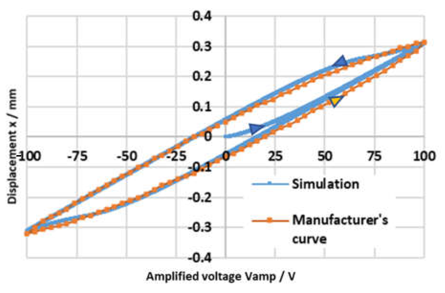
The results of the numerical simulations are now presented and discussed. Firstly, the hysteresis model was validated against the data provided by Noliac on their website [14]. Figure 4 shows the hysteresis curve (displacement of the slider x vs. amplified voltage V a m p ) provided by the manufacturer for model NAC2643 (the only hysteresis curve available), plotted as an orange curve. The simulated hysteresis curve (plotted in blue) was obtained using the above-mentioned equations with the tuned parameters α = 0.7, β = 0.013, δ = 0.03 and K b = 1.19, by applying a 1 Hz sinusoidal input voltage V c with a 5 V amplitude (from −5 V to +5 V), with no load applied (i.e., F f = C s = C p = m s = Q = 0 ), and using the characteristics of model NAC2643 ( F b , m a x = 281   N , k p = 900,000 N μ m ,   m p = 60   g ) . The amplifier employed in previous studies was assumed to be used in these simulations [20]; it is characterized by ω n , a   = 1400 rad/s and ζ a   = 1.5 (Imax = 1 A). Its cut-off frequency (calculated as the frequency at which the amplitude ratio is −3 dB) is 83 Hz. The good correspondence between the simulation curve and the manufacturer’s curve shows the accuracy of the hysteresis model.
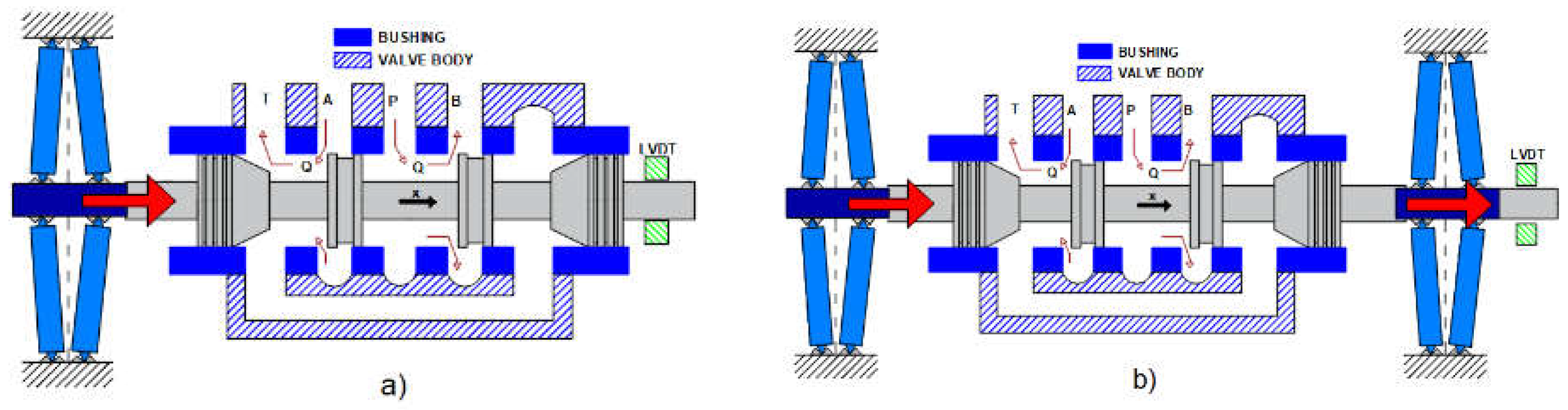
After the validation of the hysteresis model, the architecture of Figure 2a was simulated using the full numerical code described in 
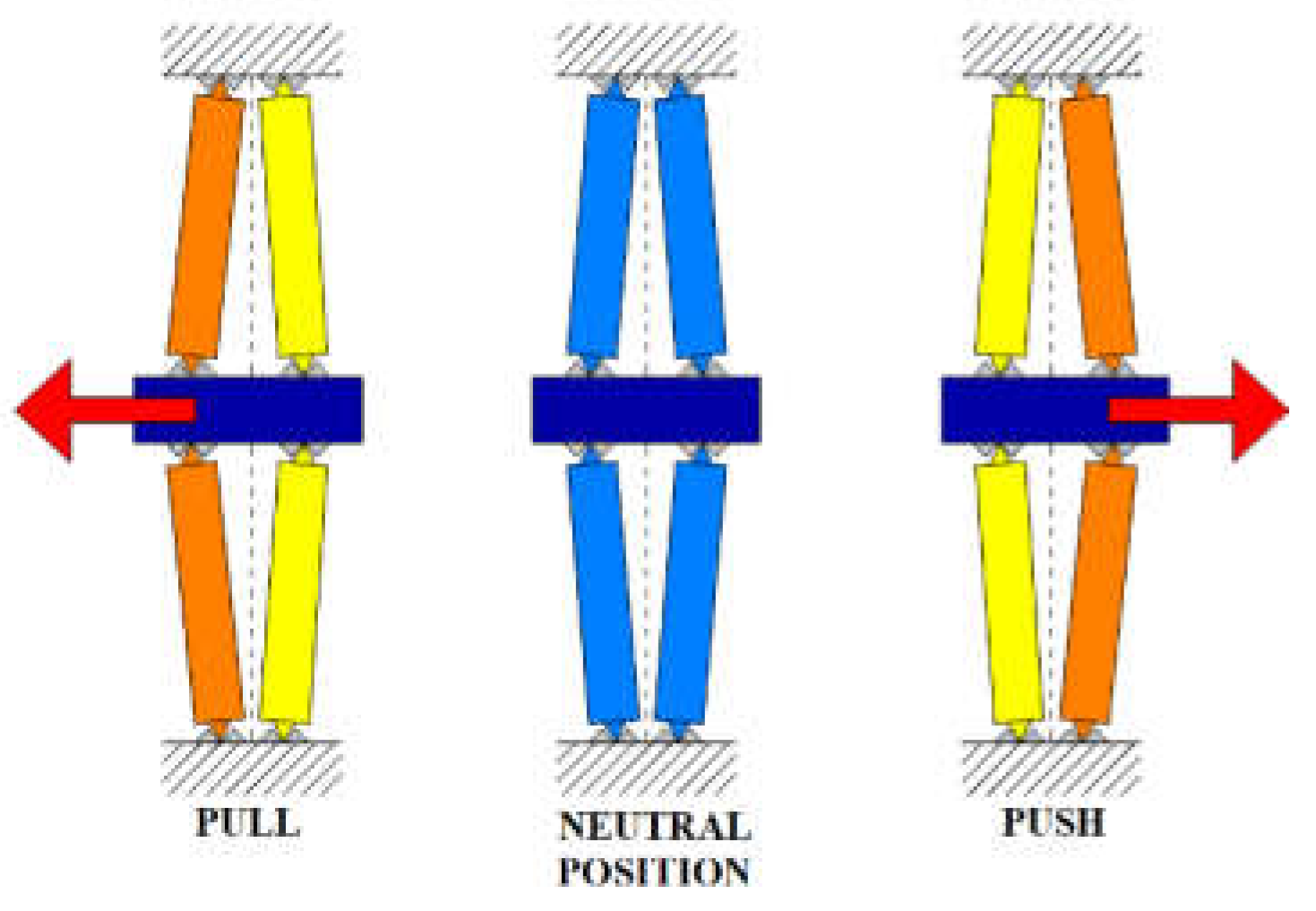
Section 2.2. The amplified piezo-stack employed in the simulations was model NAC2645, being capable of producing the highest value of maximum free stroke ( x m a x   = ±475 μm working in push/pull mode). The maximum blocking force of this model is F b , m a x = 332 N; its stiffness is k p   = 700,000 N/m. The overall mass of the amplified piezo-stack comprising the case (which is the heaviest part, being realized in stainless steel [14]) is 160 g; as already mentioned, in the simulations, the mass of the moving parts of the amplified piezo-stack m p was assumed to be one half of the overall mass, namely, m p   = 80 g. Given the very similar characteristics between model NAC2643 and model NAC2645, the same tuned parameters α = 0.7, β = 0.013, δ = 0.03 and K b = 1.19 were used in this analysis to simulate the hysteresis of model NAC2645. In this regard, 
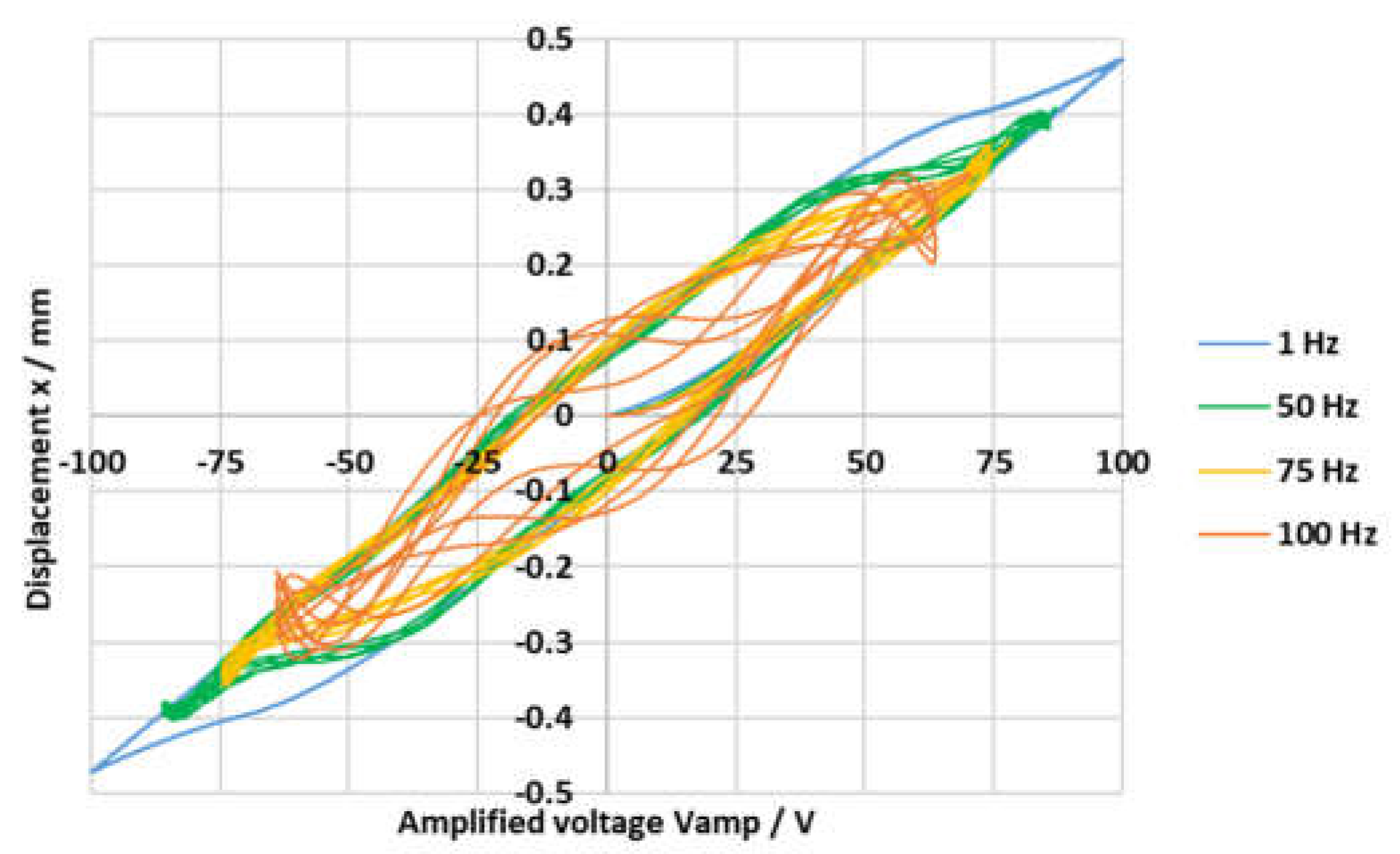
Figure 5 shows how the hysteresis curve of model NAC2645 changes according to the frequency of the input voltage V c (sine wave from −5 V to +5 V), with no load applied (i.e., F f = C s = C p = m s = Q = 0 ), and with ω n , a   = 1400 rad/s and ζ a   = 1.5 (Imax = 1 A).
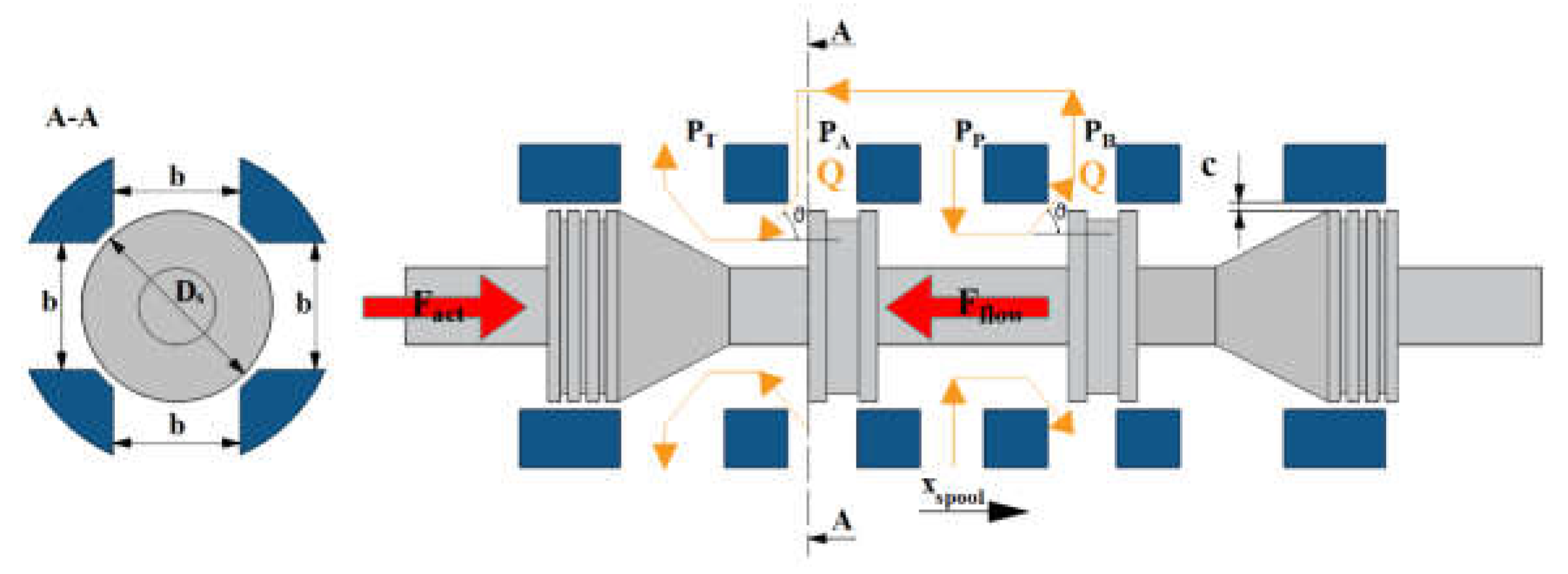
Concerning the simulation of the entire valve architecture of Figure 2a, a large size spool was used in the simulations, having a diameter of 15 mm and a mass of 30 g. The slot width was taken equal to 2/3 of the whole spool perimeter; therefore, b = 31.42 mm. The clearance was assumed to be c = 3 μm, being a typical value of servovalves [31], leading to A l , s   = 0.09425 mm2. The oil was assumed to be ISO VG 32 at 50 °C, characterized by ρ = 851 kg/m3 and μ = 0.0187 kg/(m s). The damping factor of the spool was calculated using Equation (7): assuming a spool length equal to l s = 50 mm and an eccentricity equal to ε = 1 μm (common values for servovalves [1]), the calculated damping factor is C s = 15 Ns/m.
Concerning the discharge coefficient, it was assumed, for simplicity, to be constant and equal to C D = 0.7. Because of the large pressure drops used in the simulations, this assumption can be considered valid for a large part of the spool stroke, when the flow is turbulent and, for turbulent flows, the discharge coefficient in servovalves is constant, ranging from 0.65 to 0.7 regardless of the spool position [1,33], unlike the discharge coefficient in proportional valves which can have different values even for turbulent flows depending on the notch geometry and on the spool position [34]. The flow in the metering chamber of a servovalve is laminar only for very low values of the Reynolds number, usually for Re < 200 to 400 [1,29]; therefore, an error is introduced only at the very small opening degrees, without affecting the overall simulation. Similar considerations can be made for the flow angle, whose value was experimentally and numerically estimated to be around 69° for turbulent flows in servovalves [29,30,33]. Therefore, θ = 69° was imposed in Equation (8) to calculate the flow forces. Concerning the simulation of the amplifier, it was operated from −100 V to +100 V (the control voltage V c being comprised between −5 V and +5 V, thus K a = 20), the sign of the signal determining the direction of slider movement. All these parameters are reported in Table 2 for completeness.
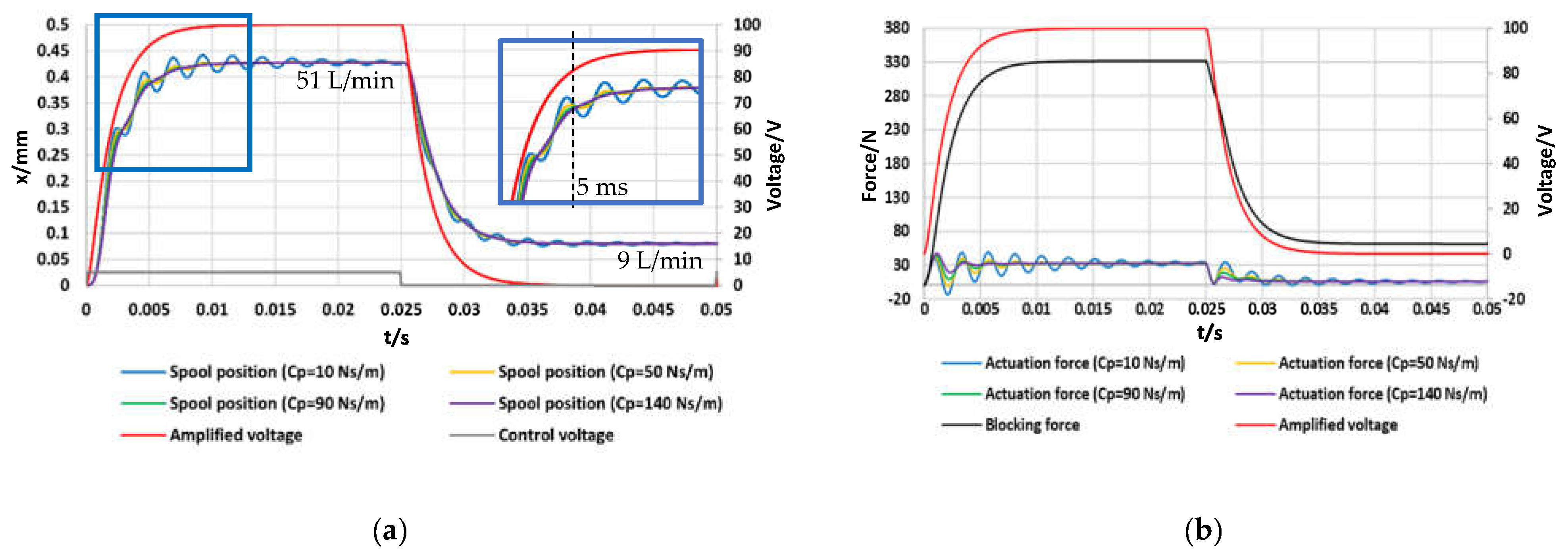
Figure 6a shows the time history of the spool position simulated in a step test in which the control voltage V c was initially changed from 0 V to +5 V, and then from +5 V to 0 V, with an inlet pressure p P = 71 bar and a discharge pressure p T = 1 bar (overall pressure drop p P p T = 70 bar), using the parameters of Table 2. Figure 6b shows the corresponding time history of the actuation force. The different curves were obtained for different values of the damping factor of the amplified piezo-stack, namely, C p = 10, 50, 90, 140 Ns/m, since the damping factor of the amplified piezo-stack depends on the geometry of the housing in which it is placed (affecting how the oil is displaced). Therefore, we can assume that it is possible to obtain these values by properly designing the geometry of the housing.
All the curves of the spool position in Figure 6a show oscillations, which are quite large for small values of C p , while becoming negligible for larger values of C p . Therefore, the response is very good for high values of C p , with less than 10 ms being predicted on average to reach a stable condition. Instead, for low values of C p , the output takes more time to reach a stable condition because of the large oscillations. This suggests that, if the housing of the amplified piezo-stack produces low values of the damping factor, changes can be made to the housing in order to increase the damping factor and reduce possible oscillations of the spool. However, in all the cases (regardless of the value of C p ), the time interval taken to reach 90% of the maximum opening is very short, being of the order of 5 ms.
The spool displacement reached for V c = +5 V is about 0.43 mm, which is similar to that achievable with linear force motors (±0.5 mm), and a high value of flow rate is achieved at the maximum opening (51 L/min for p P p T = 70 bar). When the control voltage returns to 0 V, the simulated spool position is greater than zero because of the hysteresis occurring in the amplified piezo-stack; this confirms that closed-loop controls must be employed to cope with hysteresis.
Concerning the actuation force, calculated as the difference between the blocking force ( F b ) and the internal spring force ( k p x ), the graph of Figure 6b reveals that the maximum value imposed by the manufacturer ( F a c t , m a x = 200 N at 50 °C) is never reached. This is due to the fact that the blocking force (black curve) has the same trend as the amplified voltage (red curve), and the maximum blocking force ( F b , m a x ≃ 330 N) is obtained when V a m p = +100 V. Because of the time interval taken by the amplifier to transform +5 V into +100 V, the maximum blocking force is obtained approximately in correspondence of the maximum opening, when the elastic force is maximum; as a result, the actuation force is always well below 200 N. Notably, the values of the actuation force become negative after about 2 ms for low values of the damping factor. This happens when the internal spring force momentarily exceeds the blocking force.
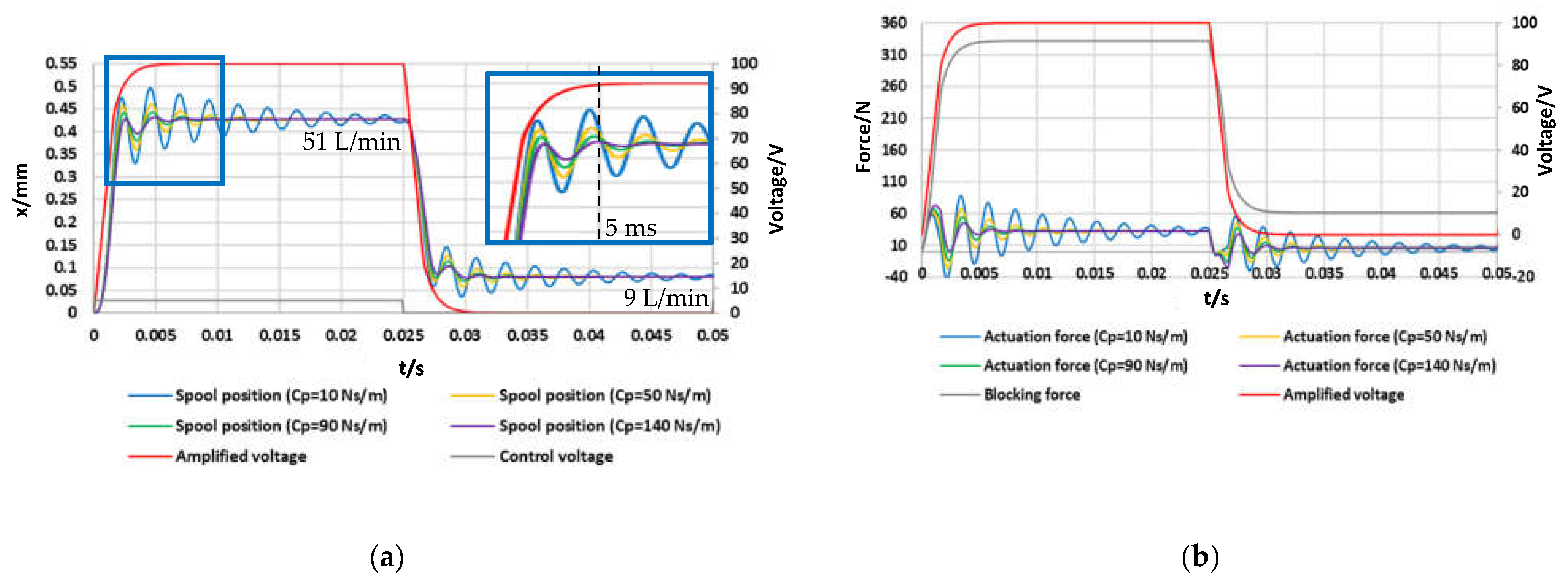
The curves of Figure 6a,b were obtained using an amplifier having ω n , a = 1400 rad/s; it is evident that the response time of this amplifier has a great effect on the response of the valve, since the blocking force has the same trend as that of the amplified voltage. To evaluate the effects of using a different amplifier, Figure 7a,b, respectively, show the time history of the spool position and of the actuation force simulated for the same conditions as those of Figure 6a,b, but using a different amplifier having ω n , a = 2800 rad/s (while maintaining ζ a = 1.5 and Imax = 1 A). Its cut-off frequency (calculated as the frequency at which the amplitude ratio is −3 dB) is 162 Hz. These curves show that the use of an amplifier with higher natural frequency can further improve the response time of the valve. Indeed, for high values of C p , the time taken to reach a stable position is only slightly longer than 5 ms. In all the cases, regardless of the value of C p , the time interval taken to reach 90% of the maximum opening is less than 3 ms, denoting a very fast response.
The results that are going to be presented from now on were obtained using the former amplifier, having ω n , a = 1400 rad/s, keeping in mind that the transient response can further be shortened by using amplifiers with higher natural frequencies. 
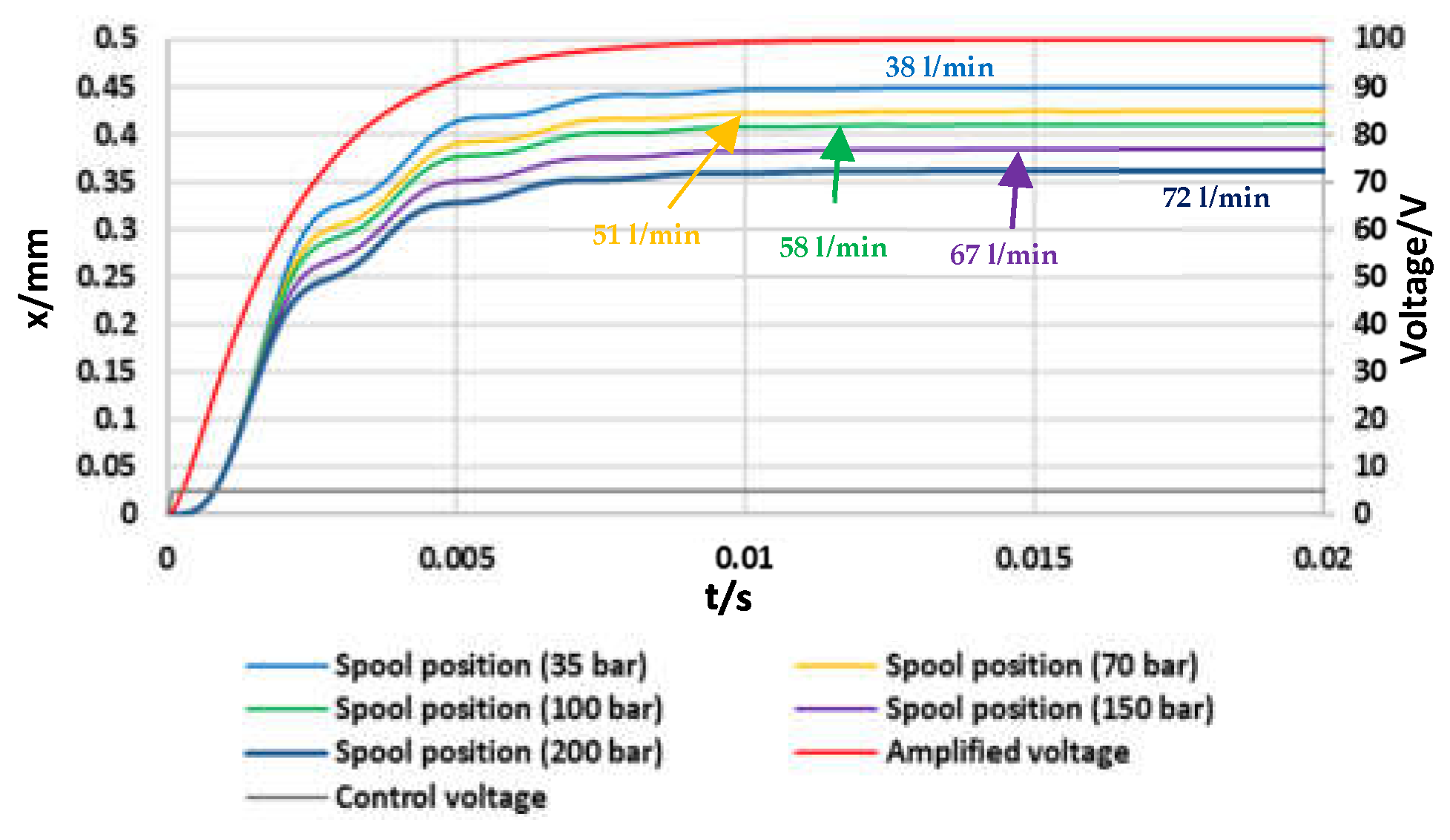
Figure 8 shows open-loop step tests, from V c = 0 V to V c = +5 V, predicted for different values of the overall pressure drop ( p P p T ). The results were obtained using the parameters of Table 2, C p = 90 Ns/m,   m p = 80 g, and ω n , a = 1400 rad/s. As shown in the graphs, the response (initial part of the spool position curve) remains almost unchanged regardless of the pressure drop, which is typical of a direct drive valve. It is noteworthy that high levels of inlet pressure can be sustained by the valve, and hence, high flow rates can be reached (72 L/min at 200 bar). Note that the final spool position (for V a m p = +100 V) slightly decreases with the pressure drop, since the flow force increases with the pressure drop.
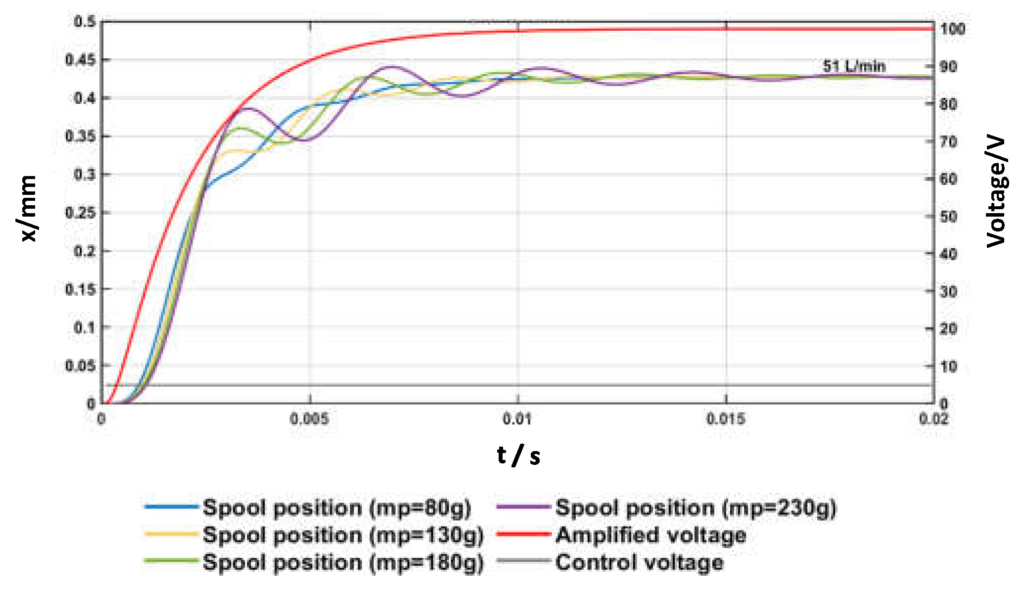
In Figure 6, Figure 7 and Figure 8, the mass of the moving parts of the amplified piezo-stack actuator was set to m p = 80 g. To evaluate the effects of the mass of the moving parts of the amplified piezo-stack upon the step response, Figure 9 shows simulated open-loop step tests for different values of this mass, namely, m p = 80, 130, 180, and 230 g (with V c being changed from 0 V to +5 V; p P p T = 70 bar; C p = 90 Ns/m; ω n , a = 1400 rad/s). These graphs reveal that large oscillations of the spool position are predicted for large values of m p . Therefore, it is also important that the mass of the moving parts of the amplified piezo-stack actuator is taken not too large, in order to limit the oscillations of the spool position and, therefore, of the flow rate.
All the results that have been presented up to this point were obtained through an open-loop control system, in order to assess the potential of the proposed architecture in terms of response speed. However, open-loop control is not able to cope with hysteresis, and closed-loop control is necessary for real applications. Therefore, closed-loop control was also simulated using a simple PI controller which changes the control signal ( V c ) according to Equation (13) to reach the target position (set point). The parameters of the PI controller, which were determined taking advantage of the Ziegler–Nichols method, are K p = 5.8 and K I = 4100. The imposed saturation limits were V c = ±5 V; the back calculation anti-windup method was used. As explained previously, this closed-loop control needs an LVDT to measure the spool position. Alternatively, in the literature, there are some open-loop control strategies with piezo-electric actuators that do not need any position sensor, are easy to handle and cost effective [35].
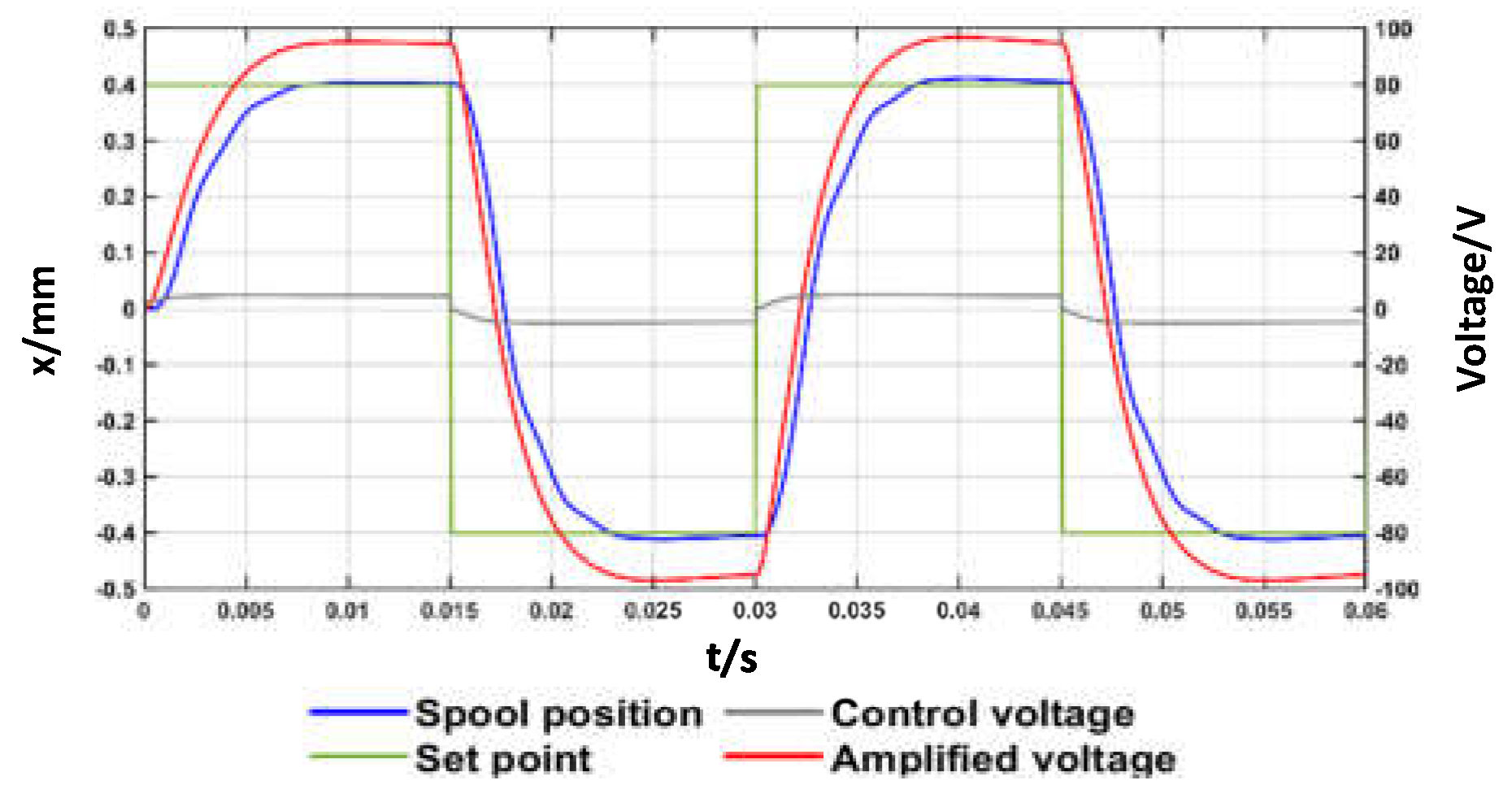
In the simulated closed-loop step tests, the set point was changed with a step size of 0.2 mm and 0.4 mm (Figure 10), and with a step size of 0.4 mm and 0.8 mm (Figure 11). In these simulated closed-loop step tests, the overall pressure difference across the valve was set to p p p T = 70 bar, with C p = 90 Ns/m and m p = 80 g. The parameters of Table 2 were used again in these simulations, along with ω n , a = 1400 rad/s.
These graphs show that the closed-loop control system allows the spool to reach the desired set points in short time intervals (overall, less than 10 ms to reach 90% of the set point). This reveals that such a simple closed-loop control system is capable of coping with the hysteresis that occurs in the amplified piezo-stack actuator.
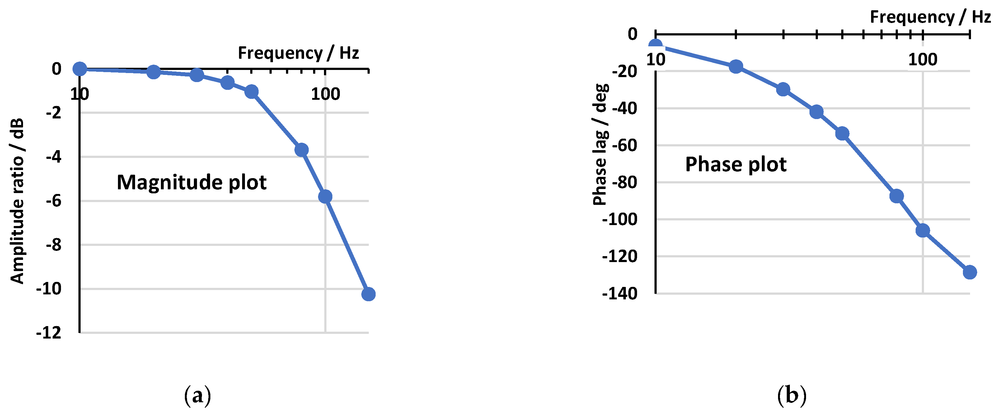
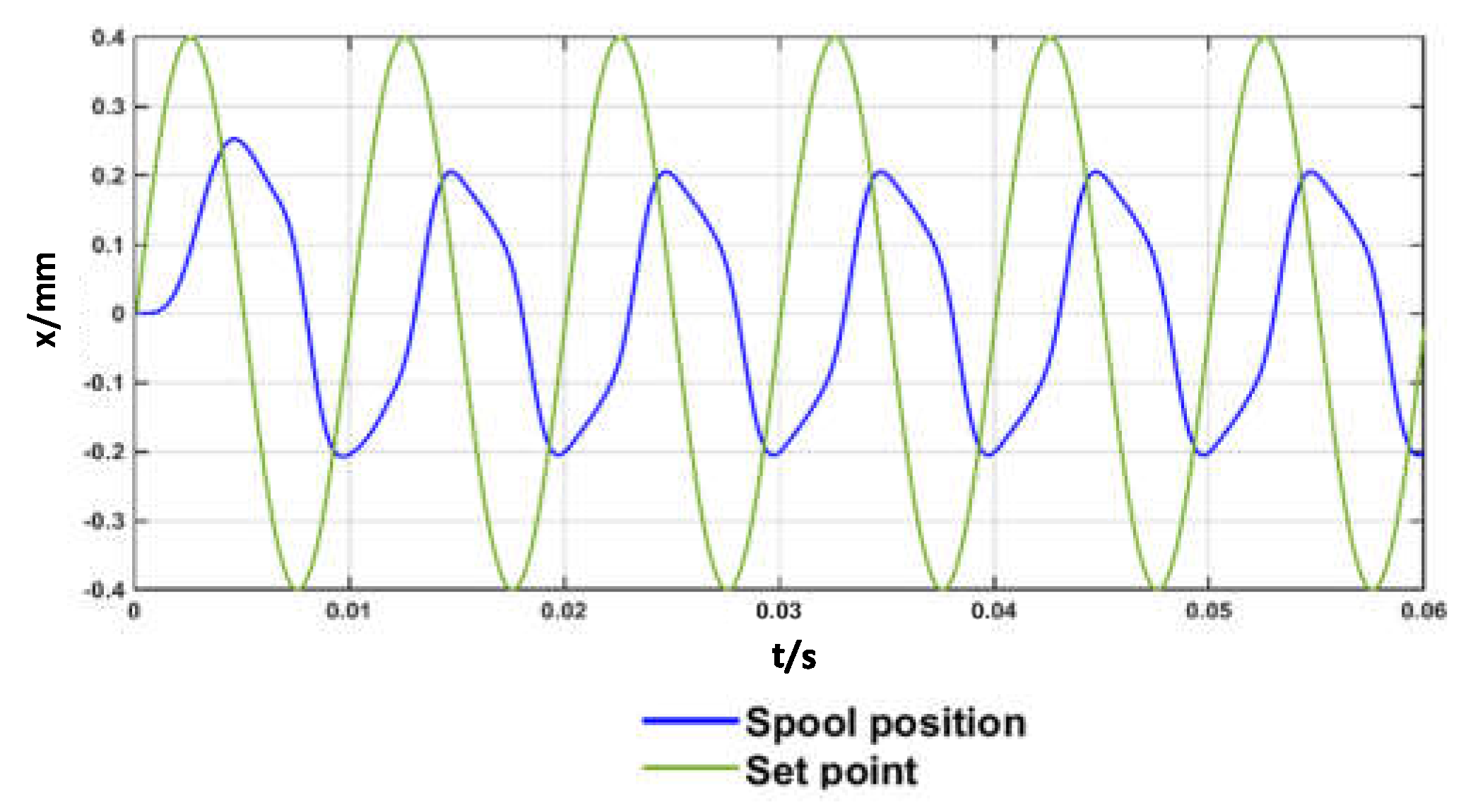
The closed-loop frequency response of the valve is now discussed. The Bode Plot of hydraulic valves, in addition to depending on the supply pressure, usually depends on the amplitude of the input signal due to nonlinearities. Therefore, the Bode Plot is often obtained for an amplitude of the input signal equal either to 50% or to 100% of the maximum value [1]. The Bode Plot predicted for the proposed valve is shown in Figure 12, including both the magnitude diagram (i.e., the amplitude ratio) and the phase diagram, obtained for p p p T = 70 bar, C p = 90 Ns/m, m p = 80 g, ω n , a = 1400 rad/s, along with the parameters of Table 2, and for an input sine wave (set point) having an amplitude of 0.4 mm (close to the maximum opening). The dimensionless amplitude ratio in dB was calculated using the formula 20   l o g 10 x o u t / x i n , where x i n = 0 .4 mm is the amplitude of the input sine wave (set point) and x o u t is the amplitude in mm of the output wave (actual spool position). The phase diagram reports the phase lag in degrees between the input wave and output wave.
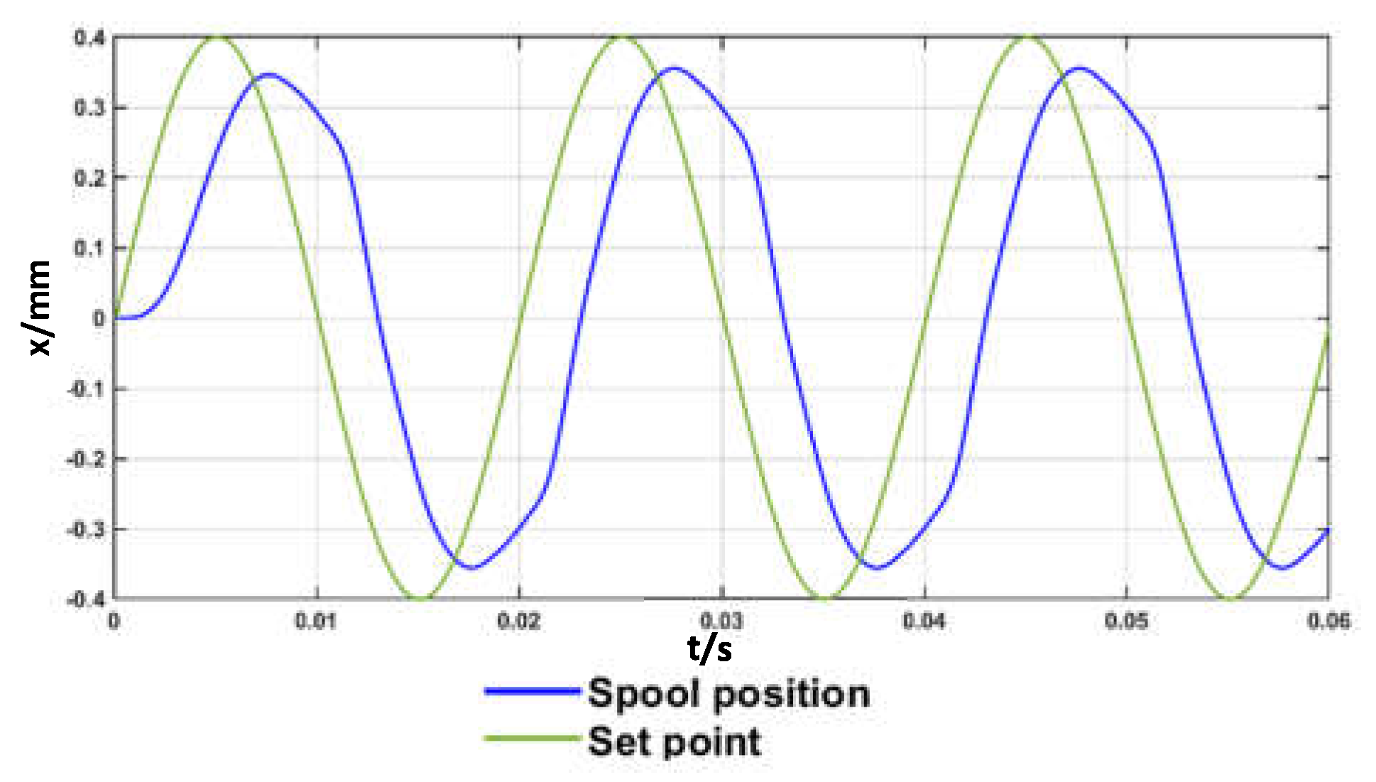
The plot shows that the predicted closed-loop frequency response is very good, with the phase shift being −54° for a frequency of 50 Hz (see Figure 13), and −105° for a frequency of 100 Hz (see Figure 14). The nonlinearity of the system is confirmed by Figure 13 and Figure 14, showing that the spool position is not exactly a sine wave.

4. Discussion

This study has assessed the idea of using commercially available amplified piezo-stacks with a diamond amplification mechanism for the actuation of direct drive servovalves. This solution has the potential to exploit the advantages that these piezo-actuators can provide, such as fast response and low weight. In this work, two architectures were proposed, depending on the number of amplified piezo-actuators used (one or two). The performance of the simpler architecture, in which only one amplified piezo-stack actuator pushes and pulls a spool inside a 4/3 valve, was evaluated using detailed and well-established equations implemented in a Simulink code. Hysteresis was simulated by an accurate model, which was validated against experimental data. The amplified piezo-stack actuator considered in the simulations was the NAC2645 model produced by Noliac, which provides values of displacement and actuation force very similar to those obtained by a linear force motor. In the simulations, a large spool was considered, having a diameter of 15 mm and a mass of 30 g. Firstly, the results obtained with an open-loop control system were presented; then, the results obtained with closed-loop spool position control, needed to cope with hysteresis, were discussed. Both step and frequency response results were included.
Through both the analysis of the characteristics of the amplified piezo-stack and the simulation results, it is possible to define the favorable aspects of the proposed architecture. The actuation forces are sufficient to overcome the opposing ones that are present in a servovalve (friction and flow forces), and the piezo-electric actuation can guarantee a fast response. In this regard, in the simulated open-loop tests, the time interval predicted to reach 90% of the maximum opening was less than 5 ms using an amplifier with 1400 rad/s natural frequency and less than 3 ms using an amplifier with 2800 rad/s natural frequency. Small oscillations in the response can be obtained, provided that the damping factor of the amplified piezo stack actuator, which can be changed by adjusting oil flow in the housing, is not too small. High inlet pressure levels can be sustained by the valve and therefore high flow rates can be achieved (about 70 L/min at 200 bar). The use of closed-loop control can allow hysteresis to be successfully coped with. A very good closed-loop frequency response was predicted, the phase shift being −105° for a frequency of 100 Hz and an amplitude of 0.4 mm, using an amplifier with 1400 rad/s natural frequency. The parameters of the closed-loop controller were determined taking advantage of the Ziegler–Nichols method; a descent approach could be used to further improve the results.
In conclusion, this analysis showed that the use of amplified piezo-stack actuators for the direct actuation of servovalves is feasible and has interesting features, especially in terms of response speed. The cost of amplified piezo-stack actuators is currently high (about 2000 euros); however, the cost could be reduced in the future by the large-scale production of these actuators.

Author Contributions

Conceptualization, P.T., E.D., A.R.P., F.S., P.D.P. and R.A.; methodology, P.T., E.D., A.R.P., F.S., P.D.P. and R.A.; software, P.T., E.D., A.R.P., F.S., P.D.P. and R.A.; writing, P.T., E.D., A.R.P., F.S., P.D.P. and R.A. All authors have read and agreed to the published version of the manuscript.

Funding

This research was supported by the European Commission under the Marie Curie Intra-European fellowship Programme. EC Grant Agreement no. 701336, H2020 MSCA Individual Fellowship: Development of a novel servovalve concept for aircraft (DNSVCFA).

Institutional Review Board Statement

Not applicable.

Informed Consent Statement

Not applicable.

Data Availability Statement

Conflicts of Interest

The authors declare no conflict of interest.

References

  1. Tamburrano, P.; Plummer, A.R.; Distaso, E.; Amirante, R. A review of electro-hydraulic servovalve research and development. Int. J. Fluid Power 2018, 20, 1–23. [Google Scholar] [CrossRef]
  2. Plummer, A.R. Electrohydraulic servovalves—Past, present, and future. In Proceedings of the 10th International Fluid Power Conference, Dresden, Germany, 8–10 March 2016; pp. 405–424. [Google Scholar]
  3. Peng, J.; Li, S.; Han, H. Damping properties for vibration suppression in electrohydraulic servo-valve torque motor using magnetic fluid. Appl. Phys. Lett. 2014, 104, 171905. [Google Scholar] [CrossRef]
  4. Kang, J.; Yuan, Z.; Sadiq, M.T.T. Numerical Simulation and Experimental Research on Flow Force and Pressure Stability in a Nozzle-Flapper Servo Valve. Process 2020, 8, 1404. [Google Scholar] [CrossRef]
  5. Yang, H.; Xu, Y.; Chen, Z.; Wang, W.; Aung, N.Z.; Li, S. Cavitation suppression in the nozzle-flapper valves of the aircraft hydraulic system using triangular nozzle exits. Aerosp. Sci. Technol. 2021, 112, 106598. [Google Scholar] [CrossRef]
  6. Saha, B.K.; Peng, J.; Li, S. Numerical and Experimental Investigations of Cavitation Phenomena Inside the Pilot Stage of the Deflector Jet Servo-Valve. IEEE Access 2020, 8, 64238–64249. [Google Scholar] [CrossRef]
  7. Saha, B.K.; Wu, Y.; Li, S. Deflector Optimization in reducing cavitation intensity in the pilot stage of deflector jet servo-valve. In Proceedings of the 2019 IEEE 8th International Conference on Fluid Power and Mechatronics (FPM), Wuhan, China, 10–13 April 2019; pp. 1500–1507. [Google Scholar]
  8. Liu, C.; Wang, Y.; Pan, T.; Zheng, G. Fault diagnosis of electro-hydraulic servo valve using extreme learning machine. Int. Trans. Electr. Energy Syst. 2020, 30, 12419. [Google Scholar] [CrossRef]
  9. Available online: http://www.moog.com/products/servovalves-servo-proportional-valves.html (accessed on 1 September 2019).
  10. Available online: https://www.moog.com/literature/ICD/Moog-Valves-D633_D634-Catalog-en.pdf (accessed on 1 September 2019).
  11. Meng, B.; Xu, H.; Liu, B.; Dai, M.; Zhu, C.; Li, S. Novel Magnetic Circuit Topology of Linear Force Motor for High Energy Utilization of Permanent Magnet: Analytical Modelling and Experiment. Actuators 2021, 10, 32. [Google Scholar] [CrossRef]
  12. Sui, L.; Xiong, X.; Shi, G. Piezoelectric Actuator Design and Application on Active Vibration Control. Phys. Procedia 2012, 25, 1388–1396. [Google Scholar] [CrossRef] [Green Version]
  13. Rakotondrabe, M.; Ivan, I.; Stihi, V.; Noveanu, S.; Minca, E. Design and modeling of a piezoelectrically actuated microvalve. Rom. J. Phys. 2011, 56, 141–149. [Google Scholar]
  14. Noliac. Available online: http://www.noliac.com/products/actuators/platestacks/ (accessed on 1 September 2017).
  15. Najafabadi, H.H.; Rezaei, S.M.; Ghidary, S.S.; Zareinejad, M.; Razi, K.; Seifabadi, R. Hysteresis compensation of piezoelectric actuators under dynamic load condition. In Proceedings of the 2007 IEEE/RSJ International Conference on Intelligent Robots and Systems, San Diego, CA, USA, 29 October–2 November 2007; pp. 1166–1171. [Google Scholar]
  16. Bertin, M.J.F.; Plummer, A.; Bowen, C.; Johnston, D.N. An Investigation of Piezoelectric Ring Benders and Their Potential for Actuating Servo Valves. In Proceedings of the ASME/BATH 2014 Symposium on Fluid Power and Motion Control, Bath, UK, 20 November 2014; Volume 6. [Google Scholar]
  17. Persson, L.J.; Plummer, A.R.; Bowen, C.R.; Brooks, I. Design and modelling of a novel servovalve actuated by a piezoelectric ring bender. In ASME/BATH 2015 Symposium on Fluid Power and Motion Control; American Society of Mechanical Engineers: New York, NY, USA, 2015; p. V001T01A043. [Google Scholar]
  18. Cheng, G.M.; Li, P.; Yang, Z.G.; Liu, J.F. Doublenozzle piezoelectric servovalve. Guangxue Jingmi Gong-cheng/Optics and Precision Engineering. Precis. Eng. 2005, 13, 276–282. [Google Scholar]
  19. Zhu, L.; Shiju, E.; Zhu, X.; Gao, C. Development of Hydroelectric Servo-Valve Based on Piezoelectric Elements. In Proceedings of the 2010 International Conference on Mechanic Automation and Control Engineering, Wuhan, China, 26–28 June 2010; pp. 3330–3333. [Google Scholar]
  20. Tamburrano, P.; Plummer, A.R.; De Palma, P.; Distaso, E.; Amirante, R. A Novel Servovalve Pilot Stage Actuated by a Piezo-electric Ring Bender: A Numerical and Experimental Analysis. Energies 2020, 13, 671. [Google Scholar] [CrossRef] [Green Version]
  21. Tamburrano, P.; Plummer, A.R.; De Palma, P.; Distaso, E.; Amirante, R. A Novel Servovalve Pilot Stage Actuated by a Piezo-Electric Ring Bender (Part II): Design Model and Full Simulation. Energies 2020, 13, 2267. [Google Scholar] [CrossRef]
  22. Zsurzsan, T.G.; Mangeot, C.; Andersen, M.A.; Zhang, Z.; Andersen, N.A. Piezoelectric stack actuator parameter extraction with hysteresis compensation. In Proceedings of the2014 16th European Conference on Power Electronics and Applications, Lappeenranta, Finland, 26–28 August 2014; pp. 1–7. [Google Scholar]
  23. Pluta, J.; Sibielak, M. Testing of Throttle Valve Prototype Controlled by Piezoelectric Stack. Solid State Phenom. 2011, 177, 47–64. [Google Scholar] [CrossRef]
  24. Branson, D.T.; Wang, F.C.; Johnston, D.N.; Tilley, D.G.; Bowen, C.R.; Keogh, P.S. Piezoelectrically actuated hydraulic valve design for high bandwidth and low performance. Proc. Inst. Mech. Eng. Part I J. Syst. Control Eng. 2011, 225, 345–359. [Google Scholar]
  25. Lindler, J.E.; Anderson, E.H. Piezoelectric direct drive servovalve. In Smart Structures and Materials 2002: Industrial and Commercial Applications of Smart Structures Technologies; International Society for Optics and Photonics: Bellingham, WA, USA, 2002; Volume 4698, pp. 488–496. [Google Scholar] [CrossRef]
  26. Jeon, J.; Han, C.; Han, Y.-M.; Choi, S.-B. A new type of a direct-drive valve system driven by a piezostack actuator and sliding spool. Smart Mater. Struct. 2014, 23, 075002. [Google Scholar] [CrossRef]
  27. Tamburrano, P.; De Palma, P.; Plummer, A.R.; Distaso, E.; Amirante, R. Feasibility study of using amplified pie-zo-stack actuators for the actuation of direct drive servovalves. In E3S Web of Conferences; EDP Sciences: Les Ulis, France, 2020; Volume 197, p. 07004. [Google Scholar]
  28. Mathworks. Matlab & Simulink. In SimscapeTM User’s Guide R2018a; Mathworks: Natick, MA, USA, 2018. [Google Scholar]
  29. Merritt, H. Hydraulic Control System; John Wiley and Sons: Hoboken, NJ, USA, 1967. [Google Scholar]
  30. Stringer, J.D. Hydraulic Systems Analysis: An Introduction; Macmillan Publishers Limited Palgrave: London, UK, 1976. [Google Scholar]
  31. Tamburrano, P.; Plummer, A.R.; Elliott, P.; Morris, W.; Page, S.; Distaso, E.; Amirante, R.; De Palma, P. 2D CFD Analysis of Servovalve Main Stage Internal Leakage. In ASME/BATH 2019 Symposium on Fluid Power and Motion Control; ASME International: Geauga, OH, USA, 2019; Volume 59339, p. V001T01A051. [Google Scholar]
  32. Available online: https://politecnicobari-my.sharepoint.com/:u:/g/personal/paolo_tamburrano_poliba_it/EdcZKi4aDPJJptxQpoG88HoBWbv6NLEbBIy54wunDmHl-w?e=PZbgch (accessed on 28 June 2021).
  33. Di Rito, G. Experiments and CFD Simulations for the Characterisation of the Orifice Flow in a Four-Way Servovalve. Int. J. Fluid Power 2007, 8, 37–46. [Google Scholar] [CrossRef]
  34. Tamburrano, P.; Plummer, A.R.; Distaso, E.; Amirante, R. A Review of Direct Drive Proportional Electrohydraulic Spool Valves: Industrial State-of-the-Art and Research Advancements. J. Dyn. Syst. Meas. Control 2019, 141, 020801. [Google Scholar] [CrossRef]
  35. Henke, A.; Kümmel, M.; Wallaschek, J. A piezoelectrically driven wire feeding system for high performance wedge-wedge-bonding machines. Mechatronics 1999, 9, 757–767. [Google Scholar] [CrossRef]
Figure 1. Operating principle of an amplified stack actuator with a diamond structure [14].
Actuators 10 00156 g001
Figure 2. Two schemes of application of amplified piezo-stack actuators with diamond structure for the direct actuation of a 4/3 servovalve: (a) one actuator; (b) two actuators.
Actuators 10 00156 g002
Figure 3. Sketch including the main parameters used in the numerical model.
Actuators 10 00156 g003
Figure 4. Hysteresis curve provided by the manufacturer compared with the hysteresis curve obtained with the simulations (model NAC2643).
Actuators 10 00156 g004
Figure 5. Simulated hysteresis curves for model NAC2645 according to different input frequencies of V c (sine wave from −5 V to +5 V).
Actuators 10 00156 g005
Figure 6. Open-loop step tests simulated for different values of C p and ω n , a = 1400 rad/s ( m p = 80 g; p P p T = 70 bar): (a) spool position; (b) actuation force.
Actuators 10 00156 g006
Figure 7. Open-loop step tests simulated for different values of C p and ω n , a = 2800 rad/s ( m p = 80 g; p P p T = 70 bar): (a) spool position; (b) actuation force.
Actuators 10 00156 g007
Figure 8. Open-loop step tests simulated for different values of p P p T ( C p = 90   Ns / m ;   m p = 80 g; ω n , a = 1400 rad/s).
Actuators 10 00156 g008
Figure 9. Open-loop step tests simulated for different values of m p ( p p p T = 70 bar,   C p = 90 Ns/m; ω n , a = 1400 rad/s).
Actuators 10 00156 g009
Figure 10. Simulated closed-loop step tests ±0.2 mm ( p p p T = 70 bar,   C p = 90 Ns/m, m p = 80 g; ω n , a = 1400 rad/s).
Actuators 10 00156 g010
Figure 11. Simulated closed-loop step tests ±0.4 mm ( p p p T = 70 bar,   C p = 90 Ns/m, m p = 80 g; ω n , a = 1400 rad/s).
Actuators 10 00156 g011
Figure 12. Bode Plot for input amplitude = 0.4 mm ( p p p T = 70 bar, C p = 90 Ns/m, m p = 80 g; ω n , a = 1400 rad/s): (a) magnitude plot; (b) phase plot.
Actuators 10 00156 g012
Figure 13. Sine wave response for input amplitude = 0.4 mm and frequency = 50 Hz ( p p p T = 70 bar, C p = 90 Ns/m, mp = 80 g; ω n , a = 1400 rad/s): spool position vs. time.
Actuators 10 00156 g013
Figure 14. Sine wave response for input amplitude = 0.4 mm and frequency = 100 Hz ( p p p T = 70 bar, C p = 90 Ns/m, mp = 80 g; ω n , a = 1400 rad/s): spool position vs. time.
Actuators 10 00156 g014
Table 1. Amplified stack actuators produced by Noliac: specifications [14].
ParameterUnitNAC2641NAC2643NAC2645
Length × Width × Heightmm14 × 70.5 × 26.114 × 102.4 × 2814 × 134.2 × 30.6
Max. free stroke (working in one direction), x m a x μm300625950
Max. free stroke (working in two directions), ± x m a x μm±150±312.5±475
Stiffness, k p N/μm1.30.90.7
Max. blocking force, F b , m a x N195281332
Max. actuation force at 20 °C, F a c t , m a x N250250250
Max. actuation force at 50 °C, F a c t , m a x N200200200
Overall mass, 2 m p g84122160
Capacitance, CapμF7.21320
Table 2. Parameters employed in the simulations.
ParameterSymbolUnitValue
Spool diameter D s mm15
Spool length l s mm50
Width of the slots bmm31.42
Spool mass m s g30
Spool damping coefficient C s Ns/m15
Clearancecμm3
Leakage area A l , s mm20.09425
Discharge coefficientCD-0.7
Flow angleθdeg69
Oil density (ISO VG 32 at 50 °C) ρ kg/m3851
Max. blocking force Fb,maxN332
Stiffness of the piezo-actuatorkpN/m700,000
CapacitanceCapμF20
Maximum currentImaxA1
Gain of the amplifierKa-20
Maximum amplified voltageVmaxV100
Hysteresis parameter α -0.7
Hysteresis parameterβ-0.013
Hysteresis parameterδ-0.03
Hysteresis parameterKb-1.19
Publisher’s Note: MDPI stays neutral with regard to jurisdictional claims in published maps and institutional affiliations.

