
Dynamic Analysis of Intermittent-Motion Conveyor Actuator

Land Transport and Mechanics Department, Kuban State Technological University, 350072 Krasnodar, Russia
Actuators 2021, 10(8), 174; https://0-doi-org.brum.beds.ac.uk/10.3390/act10080174
Submission received: 3 June 2021
/
Revised: 18 July 2021
/
Accepted: 22 July 2021
/
Published: 24 July 2021
(This article belongs to the Special Issue Modelling, Control and Condition Monitoring of Actuator-Based Land Transport Systems)
Abstract
:Conveyors are one of the important components of transport systems and are used in almost all branches of mechanical engineering. This paper investigates the dynamics of the intermittent motion conveyor mechanical system. The mechanical transmission is a planetary mechanism with elliptical gears, in which the intermittent motion of the output shaft is provided by a variable gear ratio of non-circular gears. A single-mass dynamic model is built by reducing the masses, forces and moments to the initial link, which is the input shaft of the mechanism. The solutions of the equations of initial link motion were obtained using two methods, the energy-mass method and the third-order Hermite method. Dynamic studies by the energy-mass method made it possible to determine flywheel moment of inertia to reduce the coefficient of initial link rotation irregularity. The convergence of the functions of the initial link angular velocity obtained by both methods was confirmed. The results can be used for further force analysis, strength calculations, design and manufacture of the conveyor.
1. Introduction
Transportation structures consisting of conveyors and their systems are widely used in various branches of modern industry: coal, mining, electric power, machining, chemical, food and many other fields [1,2,3]. Belt conveyors have become widespread due to their high loading capacity, speed and the possibility of transportation over long distances [4,5]. The belt is the weakest link of conveyor, therefore, a large number of papers are devoted to the strength calculations of the belt [6,7,8,9,10], as well as the diagnostics of belt conveyors using inspection robots [11] and computer vision [12,13,14,15].
For the purpose of rational mechanical design and operation of conveyors, much attention of researchers should also be paid to other components of drive systems: bearings [16], gearboxes [17], idlers [18]. The design of the conveyor actuator is currently a relatively well-known and widely studied problem, especially in the particular case when the conveyor belt moves at a constant speed. However, many production lines require stopping the conveyor belt for various operations on the product, and this issue can be solved using mechanical drives of intermittent motion.
The intermittent motion mechanisms make it possible to have the required duration stops of the output link with constant angular velocity of the input link [19]. The mechanical system “electric motor—actuator—working element (for example, a conveyor pulley)” is rational construction, since the motor operates in the most efficient constant mode, and the efficiency of the mechanical transmission is high. The most common type of mechanical device for the implementation of intermittent movement is the Maltese cross (Geneva drive) [20]. Although it has been researched and modernized [21,22] over the decades, the Geneva drive has a significant disadvantage. Intermittent movement in such mechanisms is provided due to the rupture of the kinematic chain, which leads to shocks that occur at the beginning and end of the movement phase [23].
In recent years, scholars have been increasing their attention to the research of mechanical transmissions with non-circular gears as the most effective method for realizing nonlinear transfer functions [24,25,26]. This type of mechanical transmission also makes it possible to realize the intermittent motion of the output link without breaking the kinematic chain. Non-circular gears can have various shapes, but the most common are elliptical ones [27,28,29]. This is mainly due to extensive studies of their geometry and kinematics [30,31], the solution of various problems of their manufacture [32,33].
An important place in the study of machines and actuators is given to the study of their dynamics, which makes it possible to find the laws of motion of the machine parts, to perform analysis of the forces acting on the working bodies, to identify irrationally functioning units, to investigate and optimize the operating modes of the device, as well as the overall design [34,35,36,37]. However, most of the papers on the creation of non-circular gears are devoted only to the geometry and kinematics of these mechanisms, while the issues of their dynamics are much more complex and not studied. Nevertheless, some applied problems of the dynamics of non-circular gears have been solved. For example, Xing Liu et al. [38] carried out a theoretical and experimental study of the dynamic performance of elliptical gears with rotational axes at the focus and center of the pitch ellipse. Nan Gao et al. [29] investigated parametric vibrations and instabilities of elliptical gears caused by loading torque and eccentricity vibrations. Zhiqin Cai and Chao Lin [39] presented and investigated a generalized nonlinear dynamic model of a curved gear drive based on Lagrange–Bondon graphs. Many researchers have considered the issues of dynamics in relation to practical applications of mechanical devices [38,39,40] containing non-circular gears, since dynamic models include the parameters of the technological load on the working body of the machine.
Complex nonlinear functions of fluctuations in the speed oflinks of cyclic mechanisms, which also include transmissions by non-circular gears, lead to irregular movement of the input (initial) link of the mechanism, to which the motor shaft is connected directly or through a gearbox. Speed fluctuations on the motor shaft cause vibrations of the machine body, and cause noise, vibration, and reduced drive reliability. Therefore, in this study, it is proposed to construct and study a single-mass dynamic model of the intermittent-motion conveyor actuator in order to determine the function of the angular velocity of the initial link, identify the irregularity of its motion and determine the inertial characteristics of the flywheel to reduce the coefficient of irregularity to the permissible values.
2. Description of the Conveyor Actuator Mechanical System and Problem Statement
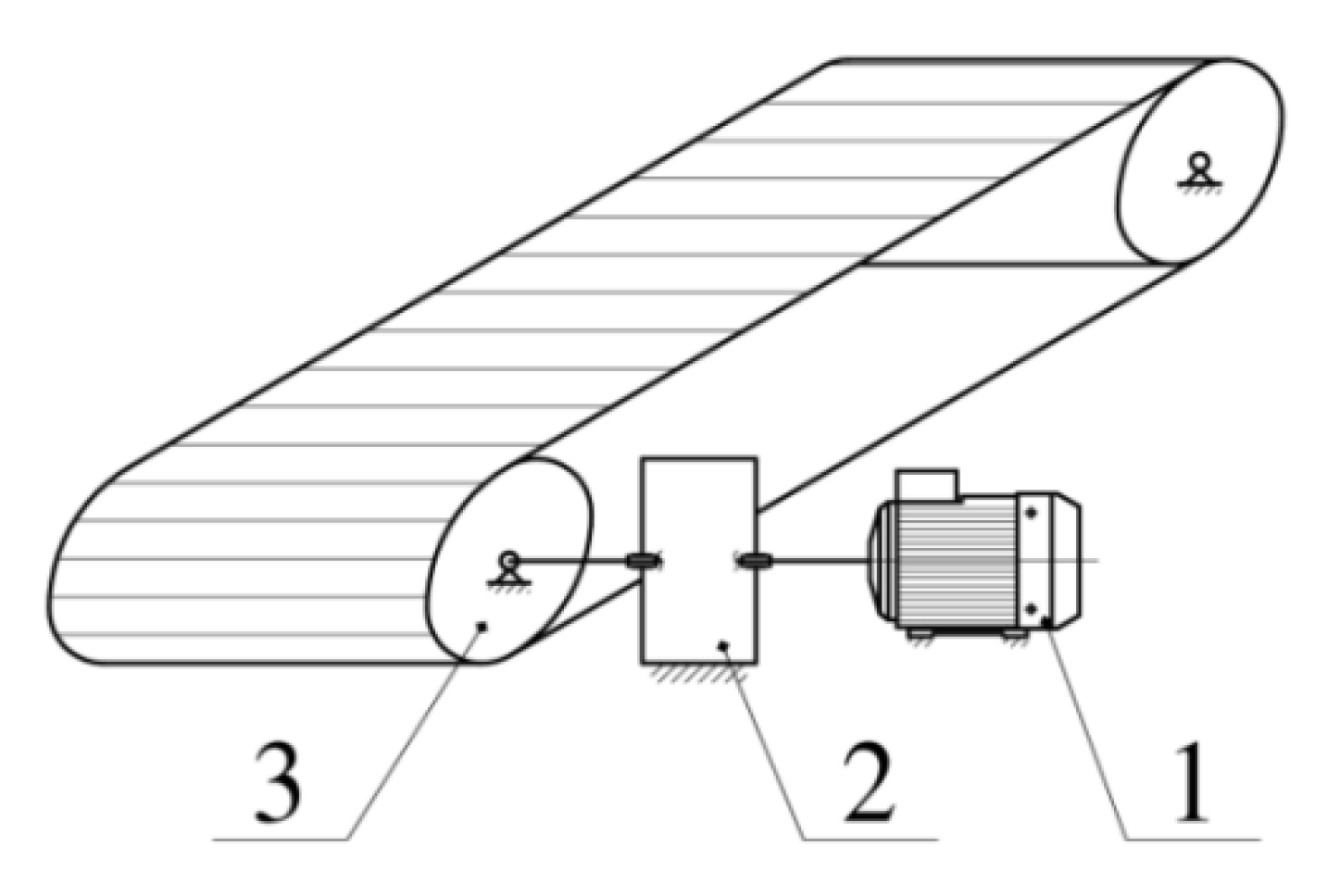
The object of research is the conveyor actuator; a simplified scheme (Figure 1) includes the electric motor 1, planetary mechanism of intermittent motion 2, and a working body 3 (drive pulley of conveyor). In the considered schematic, the motor shaft is connected directly to the input shaft of the planetary mechanism, and the axis of the drive pulley is rigidly connected to the output shaft.
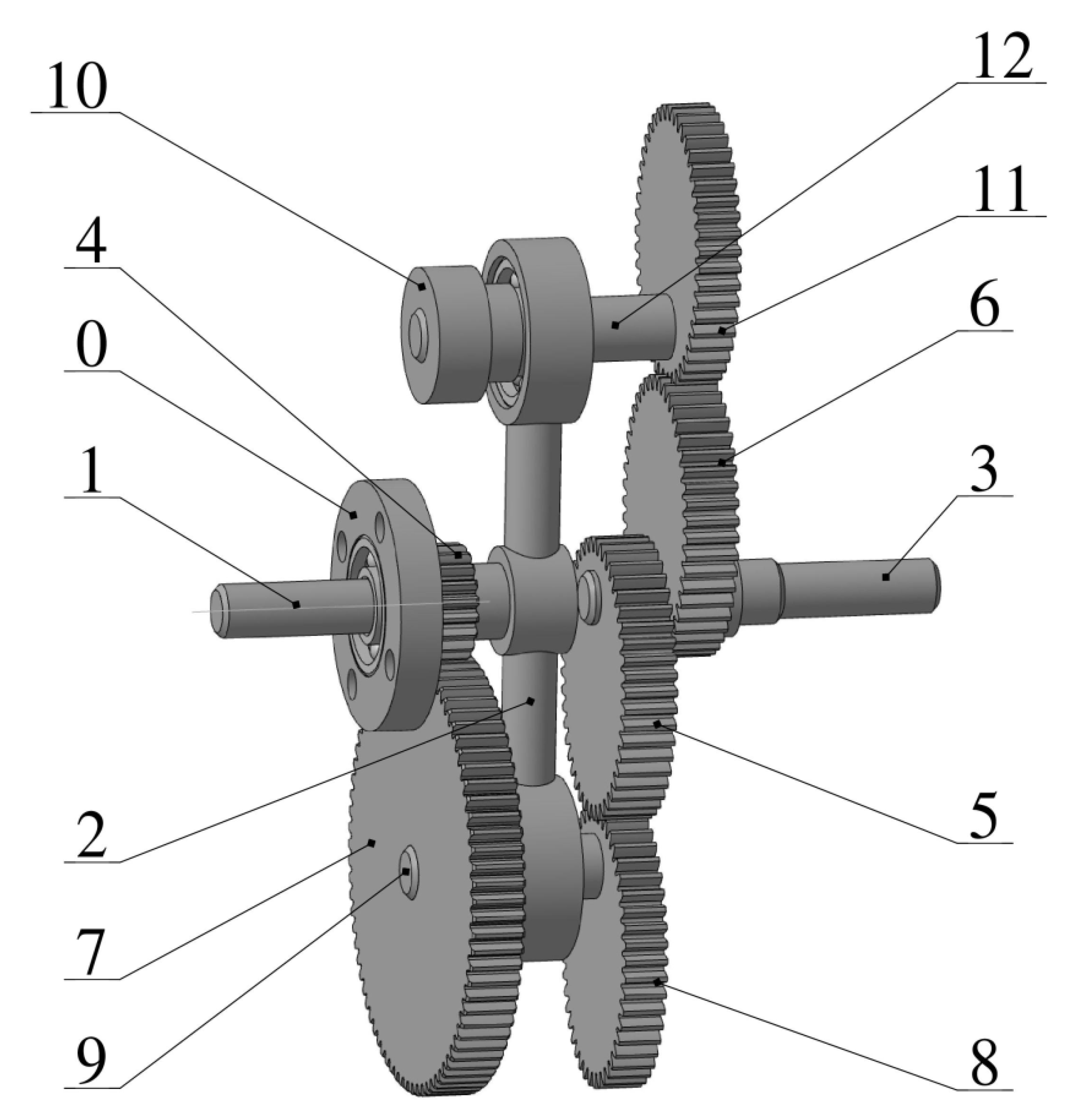
Intermittent motion of the conveyor pulley is ensured by mechanically converting the uniform rotational motion of the input shaft into non-uniform motion with stops of the output shaft. The design of the planetary gear with elliptical gears, which allows this transformation, is considered in [31] and is shown in Figure 2.
The rotation of the motor shaft is transmitted to the input shaft 1 and the carrier 2. The rotational movement of the carrier causes the spur gear 7 to roll around the fixed gear 4. Motion of the spur gear 7 is transmitted to the satellite shaft 9 and the elliptical gear 8, which drives the elliptical gear 5 and, accordingly, the output shaft 3. At the moment when the gear ratio of the pair of elliptical wheels is equal to the gear ratio of the pair of circular wheels, the output shaft 3 stops. Further, the speed of the output shaft increases to a maximum value, then decreases again to zero, which leads to an intermittent motion of the output shaft. Intermittent motion of the output link is provided in a special case: the radius of the circular gear must meet one of two conditions: or , where a and c are semi-major axis and focal distance of the pitch ellipse [31]. The second satellite, containing the counterweight 10, the elliptical gear 11 and the shaft 12, is necessary to balance the mechanism [41] and repeats the movement of the first satellite. Intermittent motion is transmitted to the driving pulley, which drives the conveyor belt and the driven pulley. Since the output shaft of the planetary mechanism rotates with stops, the load on the conveyor belt will move in translational motion with stops.
The planetary actuator has one degree of freedom, and its links are rigidly connected to each other, therefore, to solve the set problem, it is advisable to replace the real mechanism with a single-mass dynamic model, taking input shaft 1 as the reduction link. The equation of motion of the driving link for a mechanical system with one degree of freedom has the following form [42]:
where , , are the rotation angle, angular velocity and angular acceleration of the reduction link 1, is reduced to link 1 moment of inertia, is reduced to link 1 resistance moment, is reduced to link 1 driving moment.
The aim of the work is not only to find the law of motion of the reduction link , but also to conduct a deeper dynamic analysis of the mechanical system, namely, to find the driving moment, the moment of inertia of the flywheel and reduce the rotation irregularity of the drive link. Therefore, to study the obtained dynamic model, a simpler and more visual energy-mass method is used, and the verification of the obtained solutions is carried out using a numerical method, the third-order Hermite interpolation function [43].
3. Description and Construction of a Dynamic Model
3.1. Reduced Inertia Moment
The parameter characterizing the mass-inertial characteristics of the mechanism, taking into account its kinematics, is the reduced moment of inertia [42]:
where n is the number of movable links in which masses and moments of inertia are known; is the mass of the i-th link; is the moment of inertia of the i-th link relative to the axis passing through the center of mass; is the velocity analogue of the center of mass of the i-th link; is the angular velocity analogue of the of the i-th link.
Equation (2) for the investigated mechanical system will take the form:
where is the moment of inertia of the motor; is the moment of inertia of the working body. The moments of inertia and velocity analogues of the actuator links are designated in accordance with Figure 2.
Differentiating (3) with respect to the generalized coordinate , we obtain:
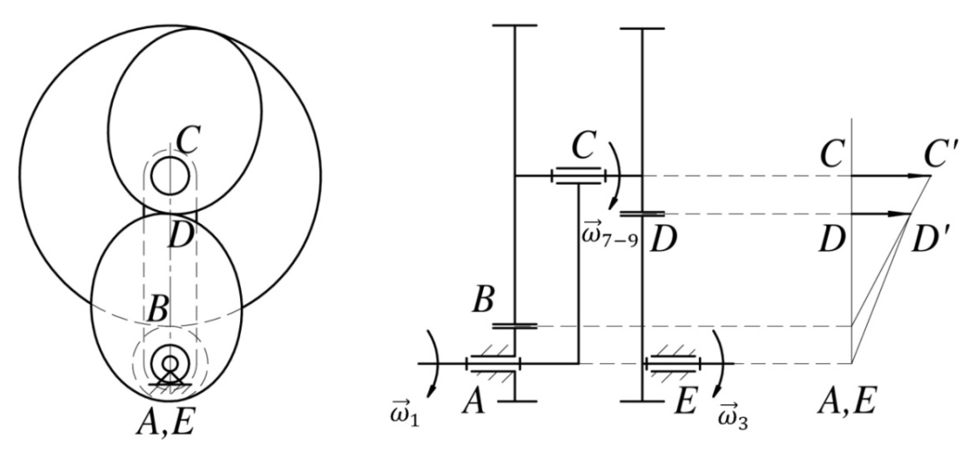
The functions of linear and angular velocities analogues, describing the kinematics of the mechanism and included in Equations (3) and (4), are determined using the plan of the velocities [44] of the mechanism links (Figure 3).
The analogue of the angular velocity of the output link 3, according to Figure 3, is defined as:
where and are the velocities of points D and C, AC and DE are the lengths of the segments in Figure 3.
Considering that from the similarity of the triangles BDD’ and BCC’, we obtain the following:
The distances AC and BC in Equation (6) are determined as:
where is the radius of the sun wheel 4, is the radius of the cylindrical wheel 6 of the satellite.
The lengths of the segments BD and DE are determined through the length of the segment CD, which is found using the equation of the centroid of the elliptical wheel [45]:
where is the angle of rotation of the elliptical wheel 8; a, e are semi-major axis and eccentricity of the pitch ellipse.
Substituting (7)–(11) into (6), we obtain an equation for determining the analogue of the output shaft angular velocity:
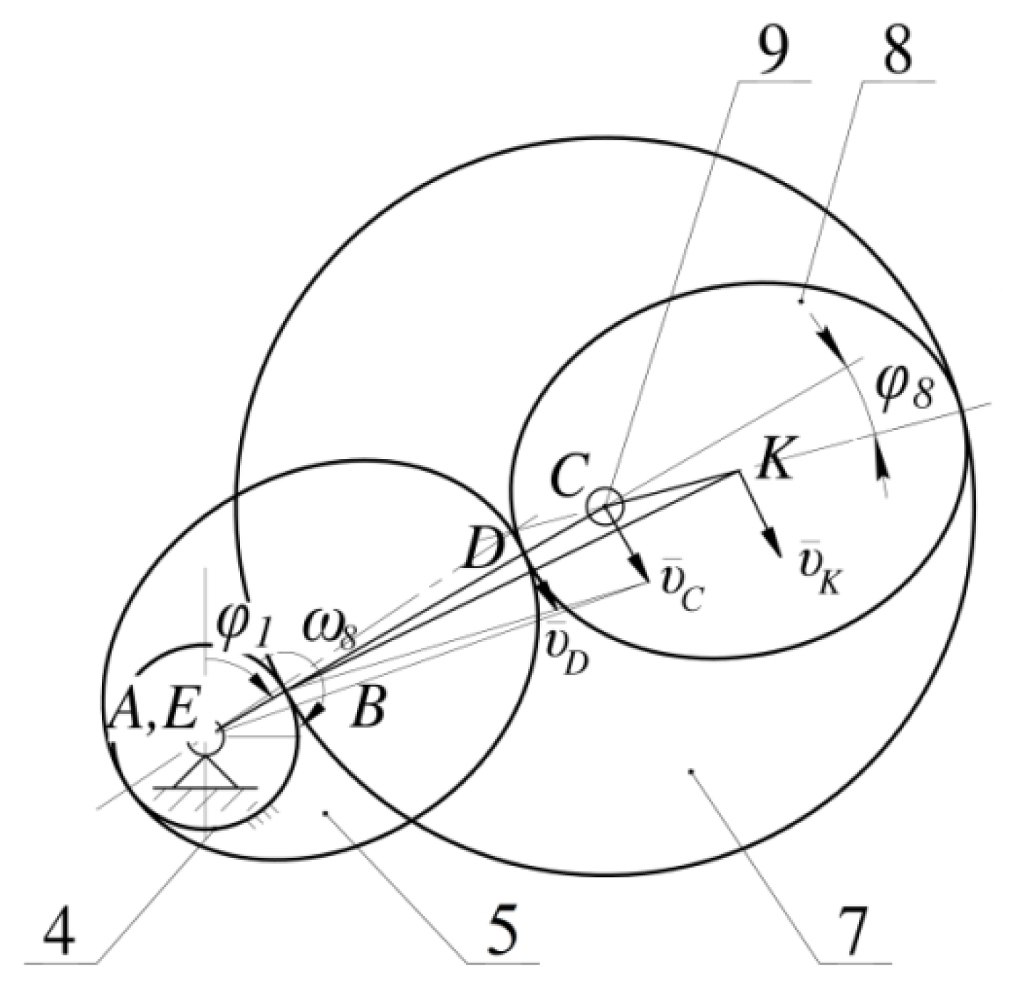
Also, to construct a dynamic model, it is necessary to determine the analogue of the angular velocity of the satellite and analogues of the linear velocities of the centers of mass of links 7, 9 (point C in Figure 4) and link 8 (point K in Figure 4) .
Velocity analogues are determined as follows:
Thus, the obtained equations of kinematics (12)–(16) make it possible to determine, using (3), (4), the reduced moment of inertia of the mechanism and its derivative.
3.2. Reduced Moment of Resistance Forces
An important parameter used in Equation (1) and characterizing the operation of the considered mechanical system is the reduced moment of resistance (). It takes into account the work of all external forces and moments (excluding the driving moment) acting on the machine: forces and moments of useful resistance forces, forces and moments of harmful resistance, gravity forces. The reduced moment of resistance forces, in the general case, is defined as:
where n is the total number of moving links; m is the number of forces F acting on the i-th link; is the velocity analogue of the force point of application; q is the number of moments M acting on the i-th link.
The forces of harmful resistance are the forces of friction acting in the kinematic pairs of the mechanism: bearings, gearing, etc. Determination of these forces is a rather difficult task, and their values are small in comparison with other resistance forces, therefore, in the conditions of the studied mechanical system, the friction forces were not taken into account.
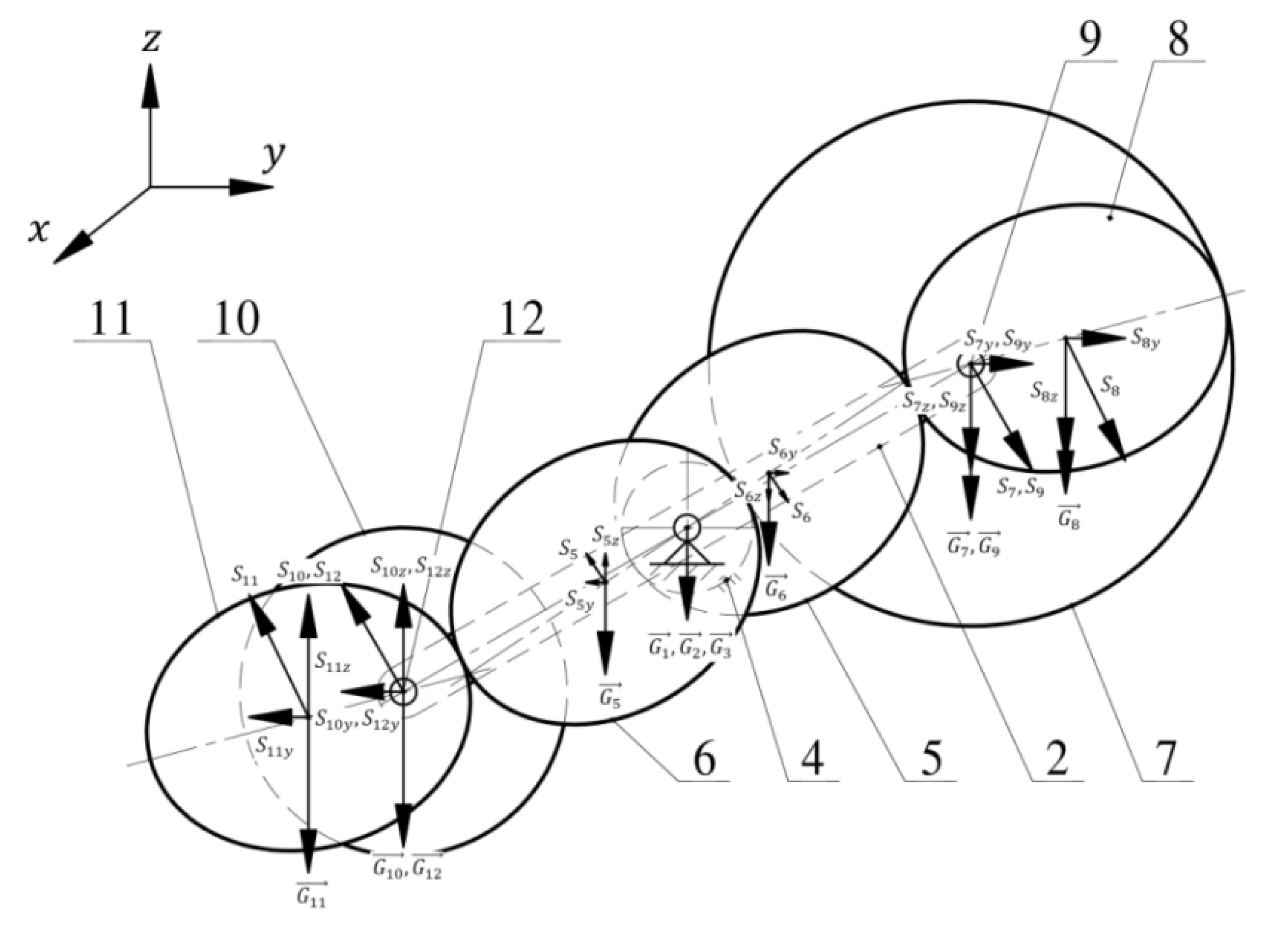
The design scheme for determining works of the gravity forces acting on the links of the mechanism is shown in Figure 5.
As can be seen from Figure 5, the axes of rotation of all links are parallel to the horizontal plane Oxy. The gravity forces of the links with the centers of mass on the fixed axes () do not perform work, since the vertical displacement in this case is equal to zero. The forces of gravity applied to the centers of mass of the satellites and elliptical gears will perform work, which is defined as:
where is the mass of the i-th link, is the displacement of the i-th link along the z axis. The masses of the links lying on the opposite satellites are equal, from the conditions of balancing the mechanism [41], and the displacements along the z-axis are equal in module, but have opposite directions. Thus, the sum of the work of all gravity forces in the investigated mechanical system will be equal to zero.
A useful resistance acts on the working body of the investigated mechanical system (the drive pulley of the conveyor), which is taken into account in the dynamic model and affects the laws of motion of the links of the mechanism. It is assumed that there is a load of constant mass on the conveyor belt, and the useful resistance is modeled by a constant moment M = 4.67 nm.
Thus, since only the moment of resistance acts on the working body in the investigated device, then Equation (17) for determining the reduced moment of resistance will take the form:
3.3. Initial Parameters for Dynamic Analysis
As an example, a conveyor with the following parameters was investigated (the numbers of the links correspond to Figure 2): Im = 100 (motor); I1 = 9.8 ; I2 = 600 ; I3 = 30.4 ; I5 = I6 = 627 ; I7 = 998 , m7 = 0.39 ; I8 = I11 = 564 , m8 = m11 = 0.09 ; I9 = 19.2 , m9 = 0.04 ; I10 = 972 , m10 = 0.38 ; I12 = 25 , m12 = 0.05 ; Iwb = 1500 (working body); R1 = 40 mm, R2= 10 mm, a = 25 mm, e = 0.6; permissible coefficient of rotation irregularity [] = 0.05. The input shaft of the actuator is driven by a motor whose rotation speed = 157 (n1 = 1500 rpm).
4. Numerical Modeling Results
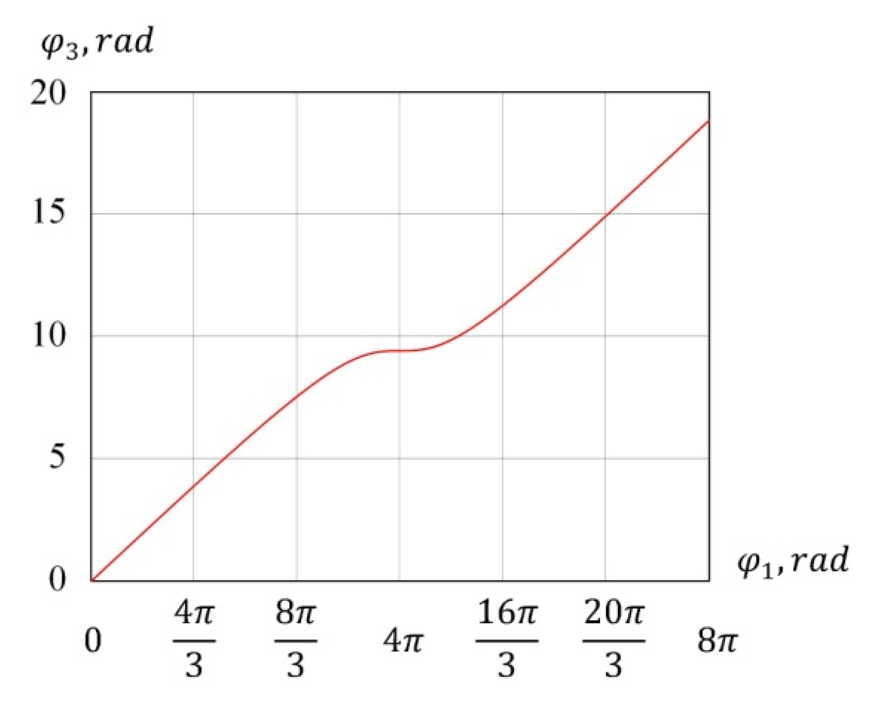
Integrating (12) over the generalized coordinate , we obtain a graph of the dependence of the angle of rotation of the output shaft on the angle of rotation of the input shaft (Figure 6).
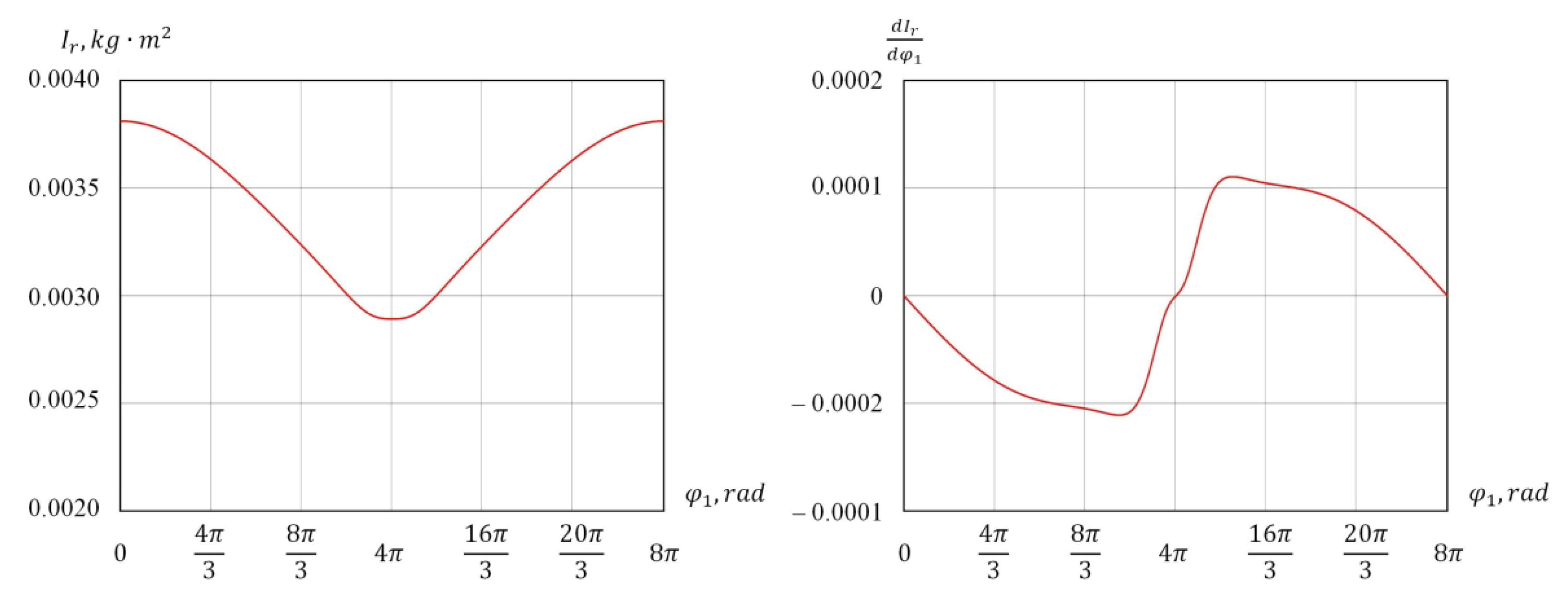
As shown on the graph in Figure 6, the output shaft makes one stop every four revolutions of the input shaft. According to Equations (3) and (4), the graphs of the functions of the reduced moment of inertia and its derivative from the angle of rotation of the input link , taking into account given initial parameters, are plotted in Figure 7.
In accordance with the energy-mass method, the increment of kinetic energy is determined as follows:
where is the work of the driving moment, is the work of the moment of resistance.
The works in Equation (20) will be determined as:
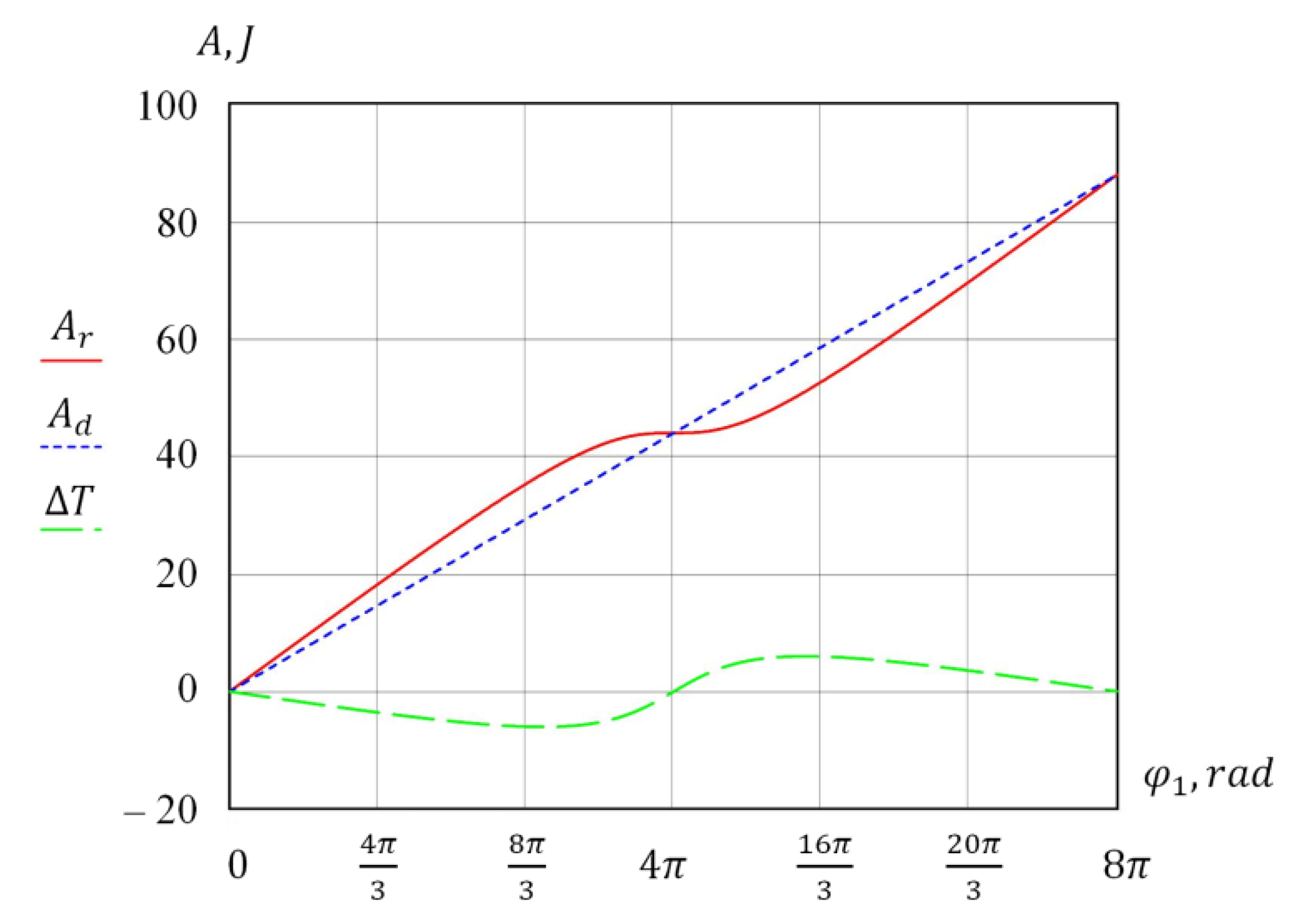
Using Equations (20)–(23), the graphs of the functions , , were obtained (Figure 8).
The angular velocity of the reduction link will be determined as [42]:
where Cmax and Cmin are determined as:
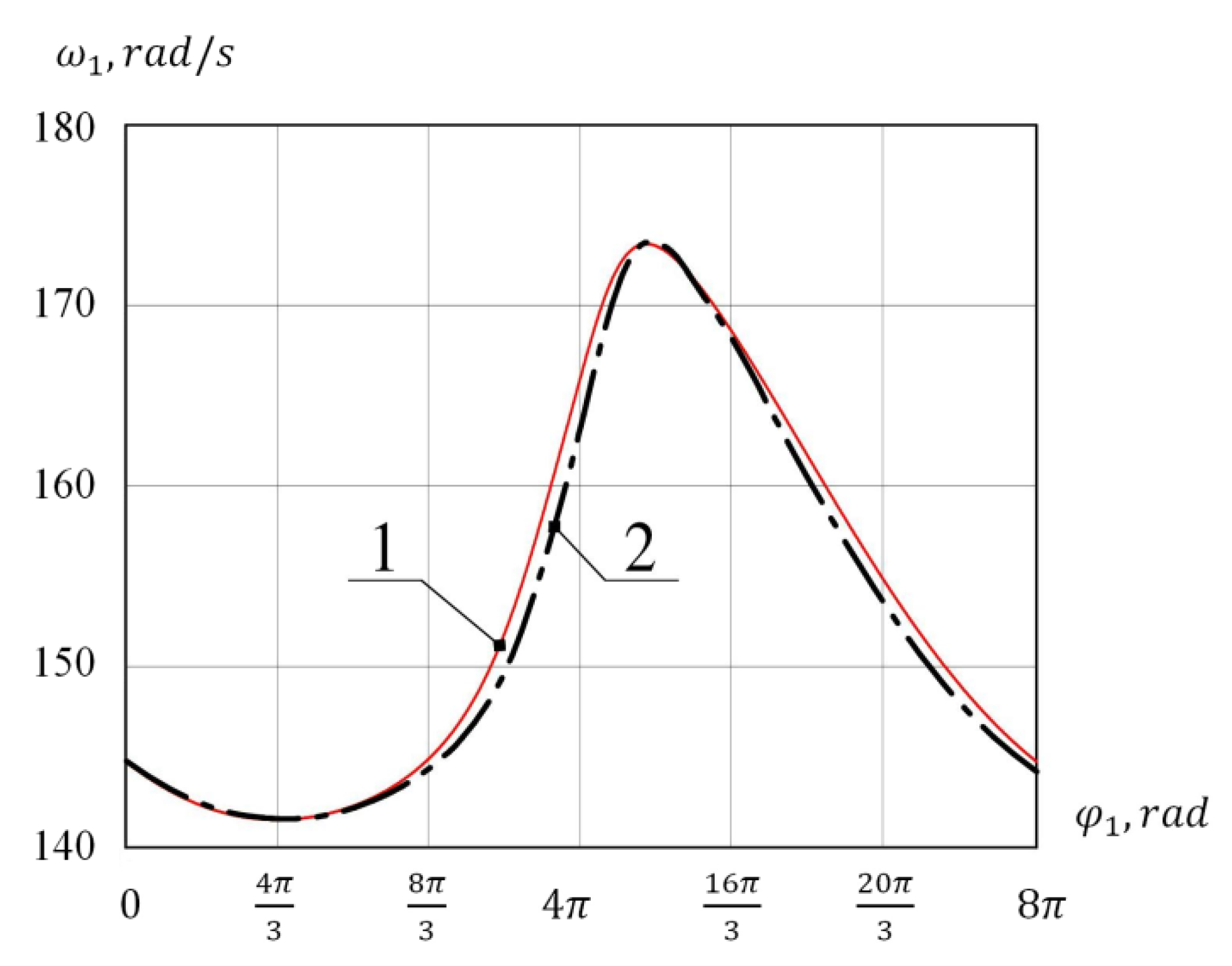
Using (24)–(26) and the calculation results (Figure 7 and Figure 8), the function was obtained. Substituting the initial data and values of and , the equation of motion of a single-mass mechanical system (1) was also solved using the third-order Hermite interpolation function. The result obtained in the form of a graph of a function is overlaid on the graph obtained by the energy-mass method, which is traditional for the study of machines (Figure 9).
It can be seen from the graph that the angular velocity of the reduction link is not a constant value and fluctuates around the average value. The velocity fluctuations are determined by the intra-cycle change in the gear ratio of the mechanism with elliptical gears. Irregularity of the initial link motion is characterized by the coefficient of rotation irregularity, which, in accordance with [42], is determined as:
Preliminary calculations showed that the value of the irregularity coefficient exceeds the permissible value [] = 0.05. Consequently, it is required to install a flywheel in the investigated actuator of the conveyor.
Flywheel moment of inertia will be determined as:
After substitution in Equation (28) , , and , the required moment of inertia of the flywheel is obtained (). Taking into account the flywheel installation, the angular velocity of the reduced link will be determined as:
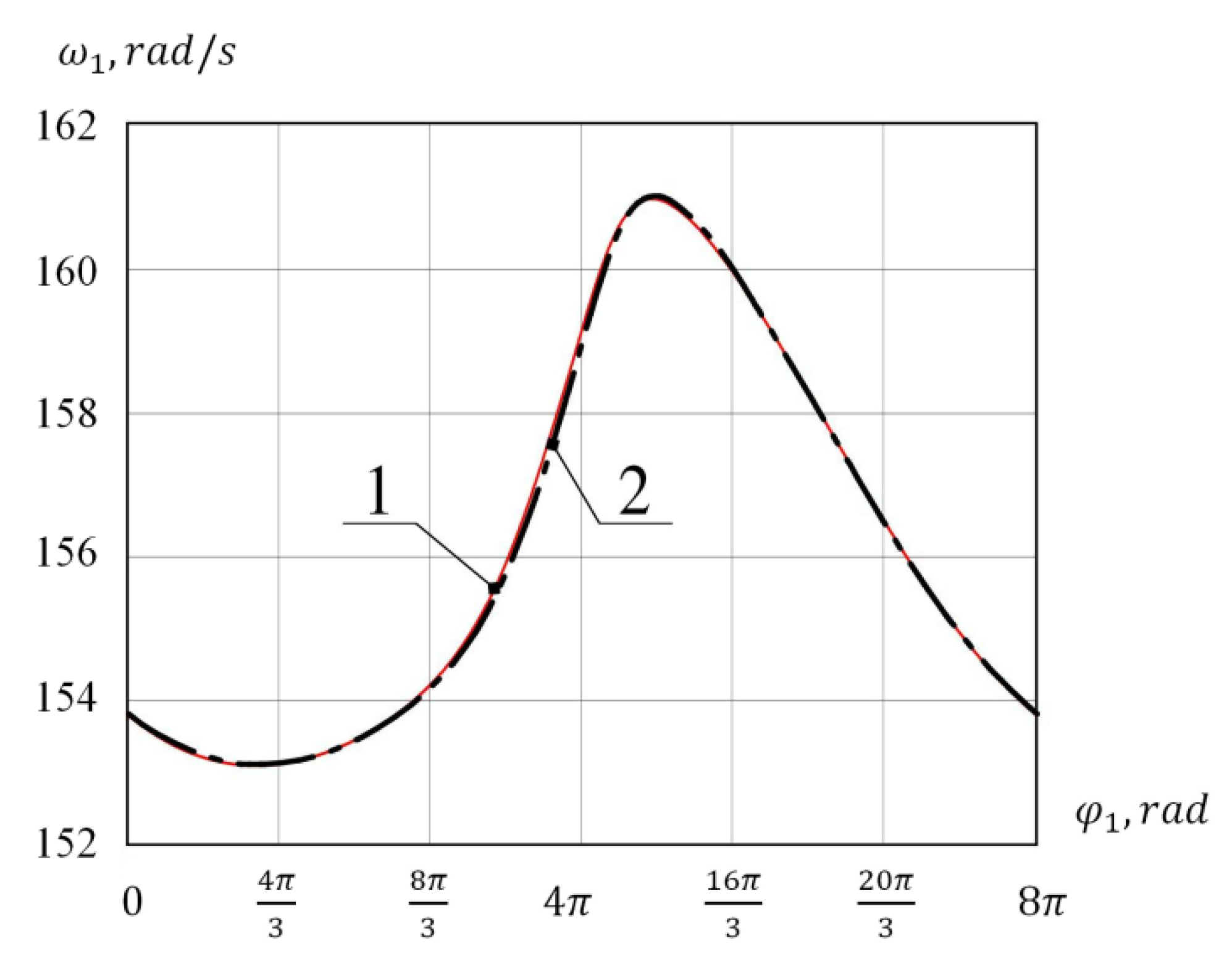
Using Equation (29) and the results of previous calculations, a graph of the function is constructed. The graph also shows the numerical solution of Equation (1) by the Hermite method, taking into account the moment of inertia of the flywheel (Figure 10).
As can be seen from the graphs, the installation of the flywheel made it possible to reduce rotation irregularity of the reduction link. The irregularity coefficient has decreased to the permissible value [] = 0.05.
5. Conclusions
In the present study, a single-mass dynamic model of the intermittent-motion conveyor, the actuator of which is a planetary mechanism with elliptical gears, is constructed and investigated. Analysis of the presented mathematical model made it possible to highlight the following innovation results and conclusions:
- laws of motion of the reduction link (the input shaft of the mechanism) are obtained using the energy-mass method and the third-order Hermite interpolation function;
- analysis of the input link rotation irregularity is carried out;
- moment of inertia of the flywheel to reduce the irregularity coefficient is determined.
Studies have shown the convergence of the laws of motion obtained by various methods. The results of dynamic analysis can be used in the design and calculation of conveyors with the proposed planetary mechanism as part of the actuator.
Funding
This research was funded by scholarship of the president of the Russian Federation, grant number SP-2763.2019.1.
Institutional Review Board Statement
Not applicable.
Informed Consent Statement
Not applicable.
Data Availability Statement
Not applicable.
Conflicts of Interest
The author declares no conflict of interest.
References
- Yao, Y.; Zhang, B. Influence of the elastic modulus of a conveyor belt on the power allocation of multi-drive conveyors. PLoS ONE 2020, 15, e0235768. [Google Scholar] [CrossRef] [PubMed]
- Gao, R.; Miao, C.; Li, X. Adaptive multi-view image mosaic method for conveyor belt surface fault online detection. Appl. Sci. 2021, 11, 2564. [Google Scholar] [CrossRef]
- Friso, D. Conveyor-belt dryers with tangential flow for food drying: Development of drying Odes useful to design and process adjustment. Inventions 2021, 6, 6. [Google Scholar] [CrossRef]
- Dong, M.W.; Luo, Q. Research and application on energy saving of port belt conveyor. Procedia Environ. Sci. 2011, 10, 32–38. [Google Scholar] [CrossRef] [Green Version]
- He, D.J.; Pang, Y.S.; Lodenijks, G. Green operations of belt conveyors by means of speed control. Appl. Energy 2017, 188, 330–341. [Google Scholar] [CrossRef]
- Zimroz, R.; Krol, R. Failure analysis of belt conveyor systems for condition monitoring purposes. Arch.Min. Sci. 2009, 128, 255–270. [Google Scholar]
- Andrejiova, M.; Grincova, A.; Marasova, D. Monitoring dynamic loading of conveyer belts by measuring local peak impact forces. Measurement 2020, 158, 107690. [Google Scholar] [CrossRef]
- Draganová, K.; Semrád, K.; Spodniak, M.; Cúttová, M. Innovative analysis of the physical-mechanical properties of airport conveyor belts. Transp. Res. Procedia 2020, 51, 20–27. [Google Scholar] [CrossRef]
- Bajda, M.; Hardygóra, M. Analysis of reasons for reduced strength of multiply conveyor belt splices. Energies 2021, 14, 1512. [Google Scholar] [CrossRef]
- Trybała, P.; Blachowski, J.; Błazej, R.; Zimroz, R. Damage detection based on 3D point cloud data processing from laser scanning of conveyor belt surface. Remote Sens. 2021, 13, 55. [Google Scholar] [CrossRef]
- Skoczylas, A.; Stefaniak, P.; Anufriiev, S.; Jachnik, B. Belt conveyors rollers diagnostics based on acoustic signal collected using autonomous legged inspection robot. Appl. Sci. 2021, 11, 2299. [Google Scholar] [CrossRef]
- Gao, Y.; Qiao, T.; Zhang, H.; Yang, Y.; Pang, Y.; Wei, H. A contactless measuring speed system of belt conveyor based on machine vision and machine learning. Measurement 2019, 139, 127–133. [Google Scholar] [CrossRef]
- Hou, C.; Qiao, T.; Zhang, H.; Pang, Y.; Xiong, X. Multispectral visual detection method for conveyor belt longitudinal tear. Measurement 2019, 143, 246–257. [Google Scholar] [CrossRef]
- Zhang, M.; Zhou, M.; Shi, H. A computer vision-based real-time load perception method for belt conveyors. Math. Probl. Eng. 2020, 2020, 8816388. [Google Scholar] [CrossRef]
- Che, J.; Qiao, T.; Yang, Y.; Zhang, H.; Pang, Y. Longitudinal tear detection method of conveyor belt based on audio-visual fusion. Measurement 2021, 176, 109152. [Google Scholar] [CrossRef]
- Wodecki, J.; Zdunek, R.; Wyomańska, A.; Zimroz, R. Local fault detection of rolling element bearing components by spectrogram clustering with semi-binary NMF. Diagnostyka 2017, 18, 3–8. [Google Scholar]
- Wodecki, J.; Michalak, A.; Zimroz, R.; Wyłomanska, A. Separation of multiple local-damage-related components from vibration data using nonnegative matrix factorization and multichannel data fusion. Mech. Syst. Signal Process. 2020, 145, 106954. [Google Scholar] [CrossRef]
- Gładysiewicz, L.; Król, R.; Kisielewski, W. Measurements of loads on belt conveyor idlers operated in real conditions. Measurement 2019, 134, 336–344. [Google Scholar] [CrossRef]
- Sclater, N.; Chironis, N.P. Mechanisms and Mechanical Devices Sourcebook; McGraw-Hill: New York, NY, USA, 2001. [Google Scholar]
- Prikhodko, A.A. Experimental kinematic analysis of an intermittent motion planetary mechanism with elliptical gears. J. Meas. Eng. 2020, 8, 122–131. [Google Scholar] [CrossRef]
- Sujan, V.A.; Meggiolaro, M.A. Dynamic optimization of Geneva mechanisms. In Proceedings of the International Conference on Gearing, Transmissions and Mechanical Systems, London, UK, 3–6 July 2000; pp. 687–696. [Google Scholar]
- Lee, J.-J.; Jan, B.-H. Design of Geneva mechanisms with curved slots for non-undercutting manufacturing. Mech. Mach. Theory 2009, 44, 1192–1200. [Google Scholar] [CrossRef]
- Kozhevnikov, S.N.; Esipenko, Y.I.; Raskin, Y.M. Mechanisms; Mechanical Engineering: Moscow, Russia, 1976. [Google Scholar]
- Zheng, F.; Hua, L.; Han, X.; Li, B.; Chen, D. Synthesis of indexing mechanisms with non-circular gears. Mech. Mach. Theory 2016, 105, 108–128. [Google Scholar] [CrossRef]
- Lin, C.; Xia, X.; Li, P. Geometric design and kinematics analysis of coplanar double internal meshing non-circular planetary gear train. Adv. Mech. Eng. 2018, 10, 1–12. [Google Scholar] [CrossRef]
- Maláková, S.; Urbanský, M.; Fedorko, G.; Molnár, V.; Sivak, S. Design of geometrical parameters and kinematical characteristics of a non-circular gear transmission for given parameters. Appl. Sci. 2021, 11, 1000. [Google Scholar] [CrossRef]
- Danieli, G.A.; Mundo, D. New developments in variable radius gears using constant pressure angle teeth. Mech. Mach. Theory 2005, 40, 203–217. [Google Scholar] [CrossRef]
- Karpov, O.; Nosko, P.; Fil, P.; Nosko, O.; Olofsson, U. Prevention of resonance oscillations in gear mechanisms using non-circular gears. Mech. Mach. Theory 2017, 114, 1–10. [Google Scholar] [CrossRef]
- Gao, N.; Meesap, C.; Wang, S.; Zhang, D. Parametric vibrations and instabilities of an elliptical gear pair. J. Vib. Control 2020, 26, 1721–1734. [Google Scholar] [CrossRef]
- Liu, J.Y.; Chang, S.L.; Mundo, D. Study on the use of a non-circular gear train for the generation of Figure-8 patterns. Proc. Inst. Mech. Eng. Part C 2006, 220, 1229–1236. [Google Scholar] [CrossRef]
- Prikhodko, A.A. Intermittent-motion planetary mechanism with elliptical gears. Russ. Eng. Res. 2020, 40, 1084–1086. [Google Scholar] [CrossRef]
- Zheng, F.; Hua, L.; Han, X.; Li, B.; Chen, D. Linkage model and manufacturing process of shaping non-circular gears. Mech. Mach. Theory 2016, 96, 192–212. [Google Scholar] [CrossRef]
- Sałacinski, T.; Przesmycki, A.; Chmielewski, T. Technological aspects in manufacturing of non-circular gears. Appl. Sci. 2020, 10, 3420. [Google Scholar] [CrossRef]
- Wojtkowiak, D.; Talaska, K.; Wilczynski, D.; Górecki, J.; Wałesa, K. Determining the power consumption of the automatic device for belt perforation based on the dynamic model. Energies 2021, 14, 317. [Google Scholar] [CrossRef]
- Prikhodko, A.A.; Smelyagin, A.I. Dynamic analysis of rotationally reciprocating stirred tank with multiple impellers. In Proceedings of the 2015 International Conference on Mechanical Engineering, Automation and Control Systems, Tomsk, Russia, 1–4 December 2015. [Google Scholar]
- Braune, S.; Liu, S.; Mercorelli, P. Design and control of an electromagnetic valve actuator. In Proceedings of the 2006 IEEE Conference on Computer Aided Control System Design, 2006 IEEE International Conference on Control Applications, 2006 IEEE International Symposium on Intelligent Control, Munich, Germany, 4–6 October 2006. [Google Scholar]
- Su, Y.; Zheng, C.; Mercorelli, P. Velocity-free friction compensation for motion systems with actuator constraint. Syst. Signal Process. 2021, 148, 107132. [Google Scholar] [CrossRef]
- Liu, X.; Nagamura, K.; Ikejo, K. Analysis of the dynamic characteristics of elliptical gears. J. Adv. Mech. Des. Syst. Manuf. 2012, 6, 484–497. [Google Scholar] [CrossRef] [Green Version]
- Cai, Z.; Lin, C. Dynamic model and analysis of nonlinear vibration characteristic of a curve-face gear drive. J. Mech. Eng. 2017, 63, 161–171. [Google Scholar] [CrossRef]
- Zhao, Y.; Yu, G.H.; Wu, C.Y. Circuit Simulation and Dynamic Analysis of a Transplanting Mechanism with Planetary Elliptical Gears. Trans. ASABE 2011, 54, 1179–1188. [Google Scholar] [CrossRef]
- Prikhodko, A.A.; Smelyagin, A.I. Balancing of the planetary actuator of the reciprocating stirring device. Mech. Eng. Autom. 2016, 4, 62–67. (In Russian) [Google Scholar]
- Prikhodko, A.A.; Smelyagin, A.I. Dynamics of rotationally reciprocating stirred tank with planetary actuator. J. Phys. Conf. Ser. 2017, 858, 12026. [Google Scholar] [CrossRef] [Green Version]
- Yazici, A.; Altas, I.; Ergenc, T. Symbolic polynomial interpolation using Mathematica. In International Conference on Computational Science; Springer: Berlin/Heidelberg, Germany, 2004; pp. 364–369. [Google Scholar]
- Prikhodko, A.A. Structural and kinematic analysis of a stirred tank planetary drive. MATEC Web Conf. 2018, 226, 1012. [Google Scholar] [CrossRef]
- Litvin, F.L.; Fuentes, A. Gear Geometry and Applied Theory, 2nd ed.; Cambridge University Press: Cambridge, UK, 2004. [Google Scholar]
Figure 1.
Scheme of the conveyor actuator.

Figure 2.
Intermittent motion planetary mechanism with elliptical gears.

Figure 3.
Plan of the mechanism velocities.

Figure 4.
Scheme for determining the velocities and .

Figure 5.
Scheme for determining works of the gravity forces.

Figure 6.
Graph of function .

Figure 7.
Graphs of functions , .

Figure 8.
Graphs of functions , , .

Figure 9.
Graphs of function without flywheel: 1—the energy-mass method, 2—the third-order Hermite interpolation function.
Figure 9.
Graphs of function without flywheel: 1—the energy-mass method, 2—the third-order Hermite interpolation function.

Figure 10.
Graphs of function with flywheel: 1—the energy-mass method, 2—the third-order Hermite interpolation function.
Figure 10.
Graphs of function with flywheel: 1—the energy-mass method, 2—the third-order Hermite interpolation function.

Publisher’s Note: MDPI stays neutral with regard to jurisdictional claims in published maps and institutional affiliations. |
© 2021 by the author. Licensee MDPI, Basel, Switzerland. This article is an open access article distributed under the terms and conditions of the Creative Commons Attribution (CC BY) license (https://creativecommons.org/licenses/by/4.0/).
Share and Cite
MDPI and ACS Style
Prikhodko, A. Dynamic Analysis of Intermittent-Motion Conveyor Actuator. Actuators 2021, 10, 174. https://0-doi-org.brum.beds.ac.uk/10.3390/act10080174
AMA Style
Prikhodko A. Dynamic Analysis of Intermittent-Motion Conveyor Actuator. Actuators. 2021; 10(8):174. https://0-doi-org.brum.beds.ac.uk/10.3390/act10080174
Chicago/Turabian StylePrikhodko, Alexander. 2021. "Dynamic Analysis of Intermittent-Motion Conveyor Actuator" Actuators 10, no. 8: 174. https://0-doi-org.brum.beds.ac.uk/10.3390/act10080174
Note that from the first issue of 2016, this journal uses article numbers instead of page numbers. See further details here.