
Identification of Bearing Dynamic Parameters and Unbalanced Forces in a Flexible Rotor System Supported by Oil-Film Bearings and Active Magnetic Devices

Abstract
:1. Introduction
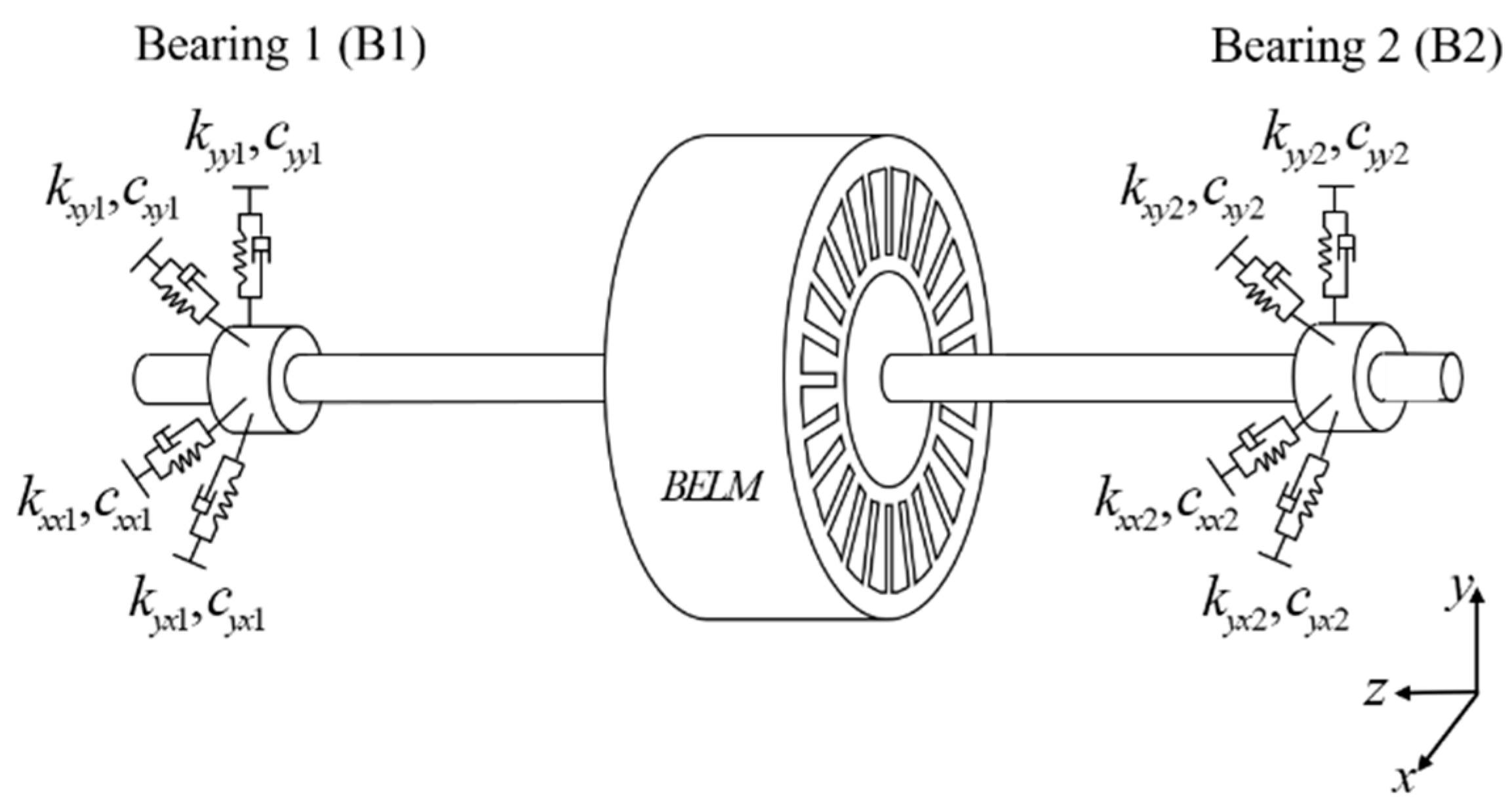
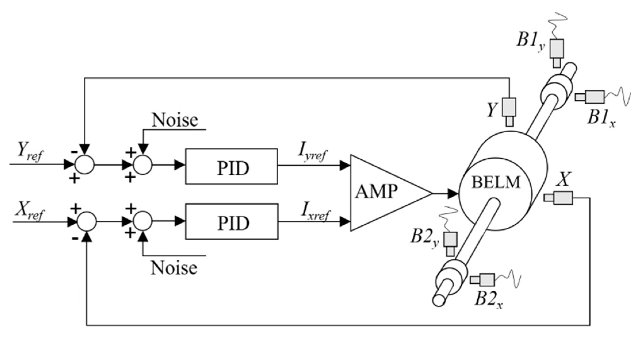
2. System Modeling
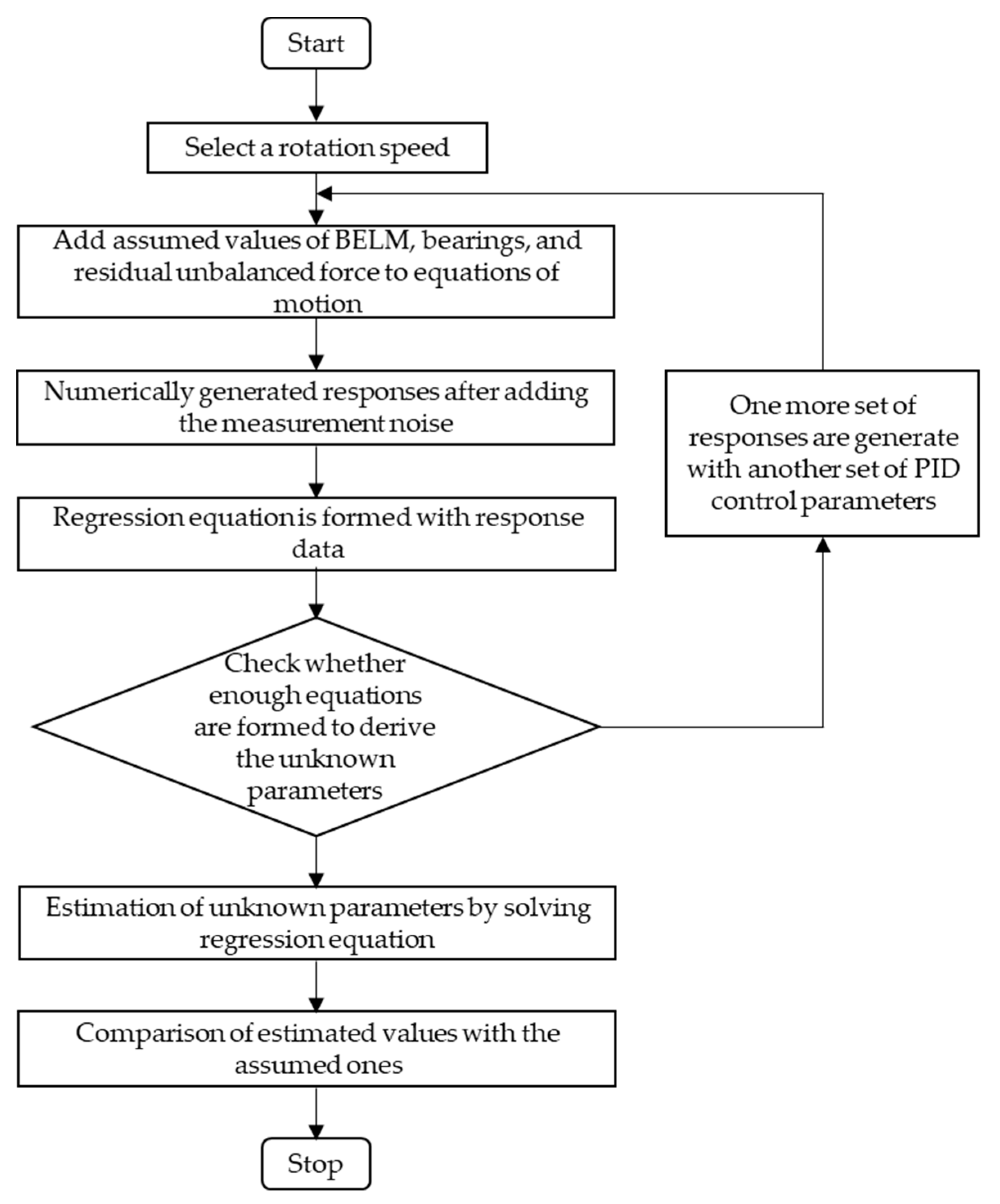
3. Identification Algorithm
- A1,1 = A2,3 = −B1xA, A1,2 = A2,4 = −B1yA, A1,5 = A2,7 = −jΩB1xA, A1,6 = A2,8 = −ΩB1yAj
- A3,17 = XA, A3,18 = IxA, A3,21 = 0.5, A3,22 = −0.5j
- A4,19 = YA, A4,20 = IyA, A4,23 = 0.5, A4,24 = −0.5j
- A5,9 = A6,11 = −B2xA, A5,10 = A6,12 = −B2yA, A5,13 = A6,15 = −ΩB2xAj, A5,14 = A6,16 = −ΩB2yAj
- A7,1 = A8,3 = −B1xB, A7,2 = A8,4 = −B1yB, A7,5 = A8,7 = ΩB1xBj, A7,6 = A8,8 = ΩB1yBj
- A9,17 = XB, A9,18 = IxB, A9,21 = 0.5, A9,22 = 0.5j
- A10,19 = YB, A10,20 = IyB, A10,23 = 0.5, A10,24 =0.5j
- A11,9 = A12,11 = −B2xB, A11,10 = A12,12 = −B2yB, A11,13 = A12,15 = ΩB2xBj, A11,14 = A12,16 = ΩB2yBj
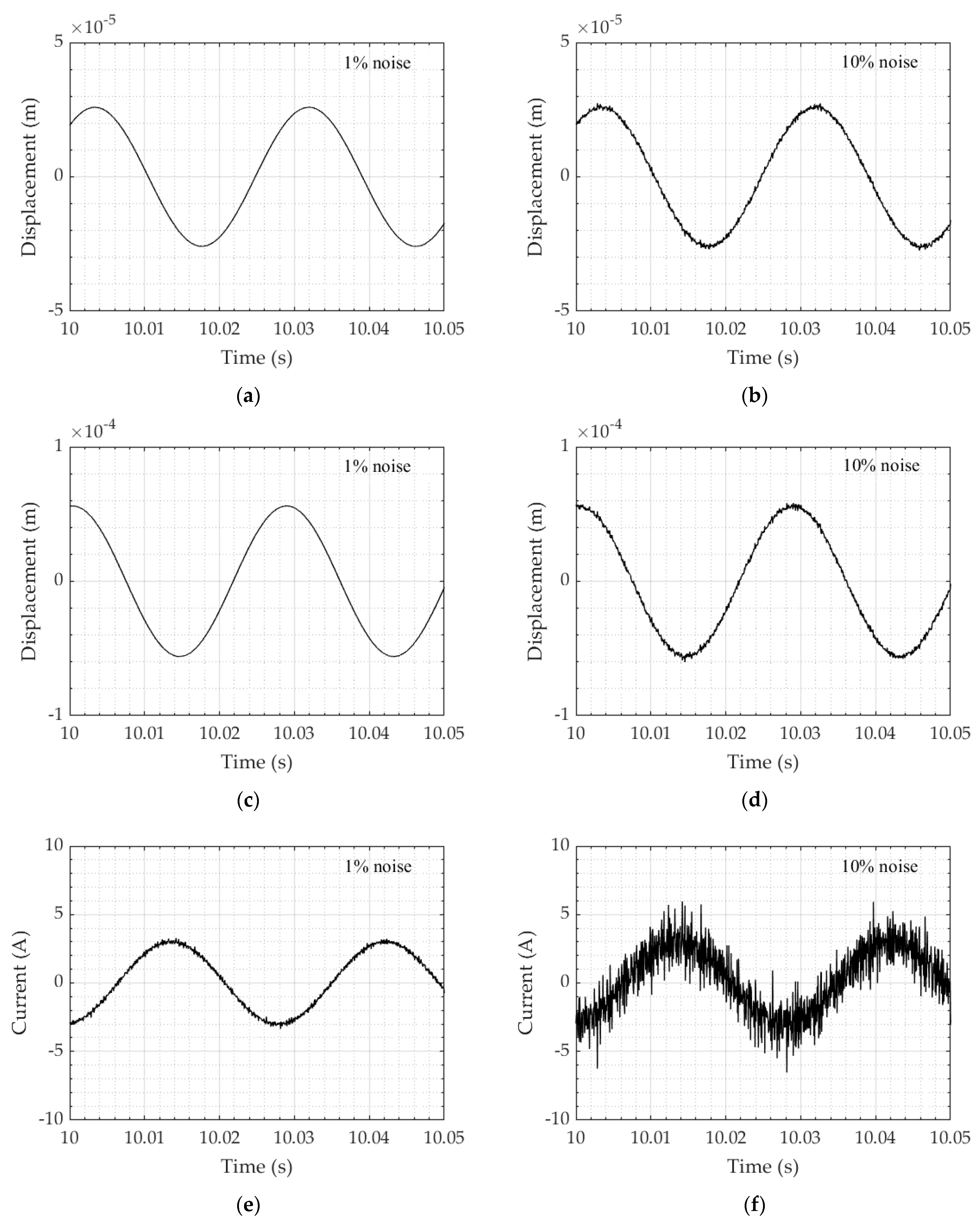
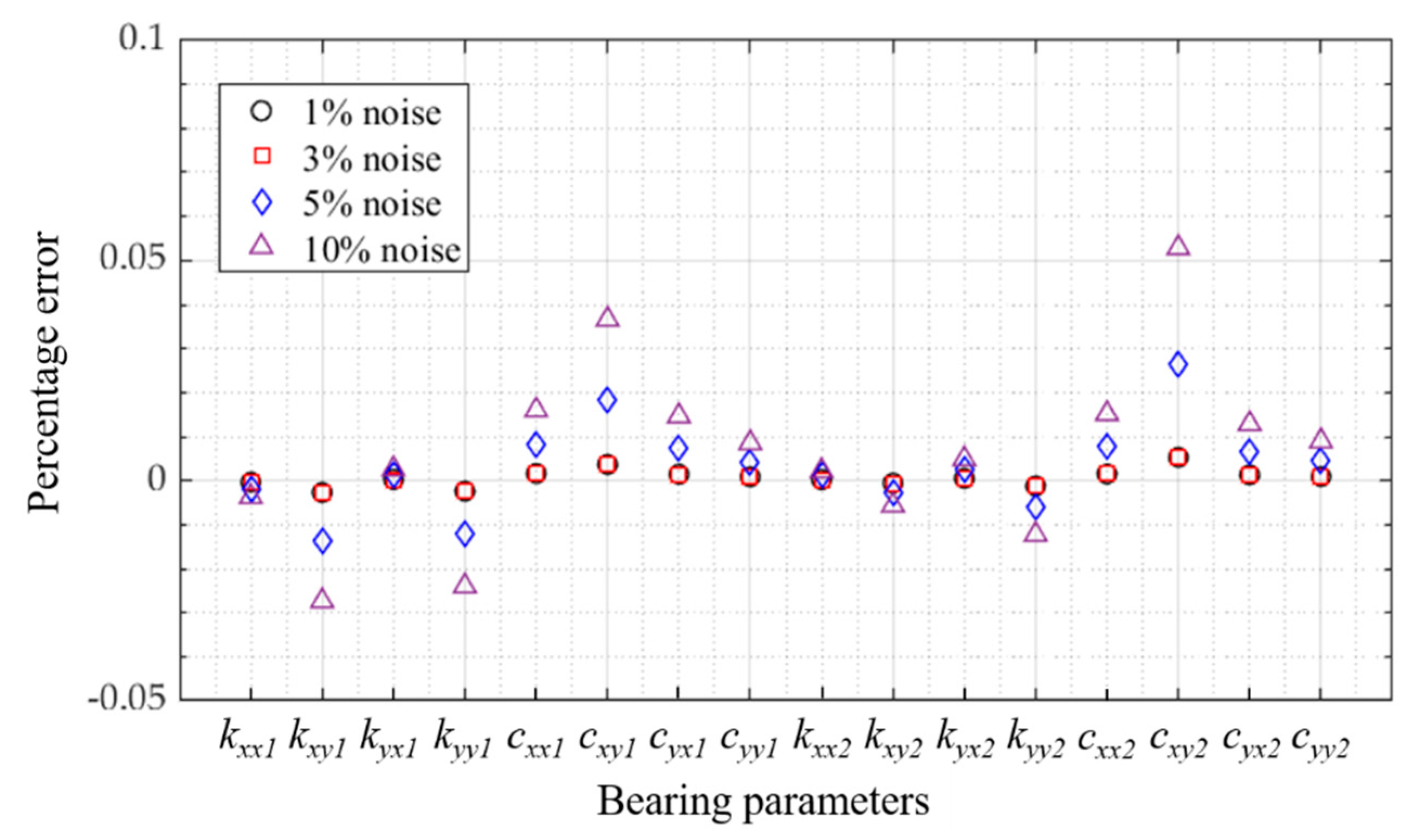
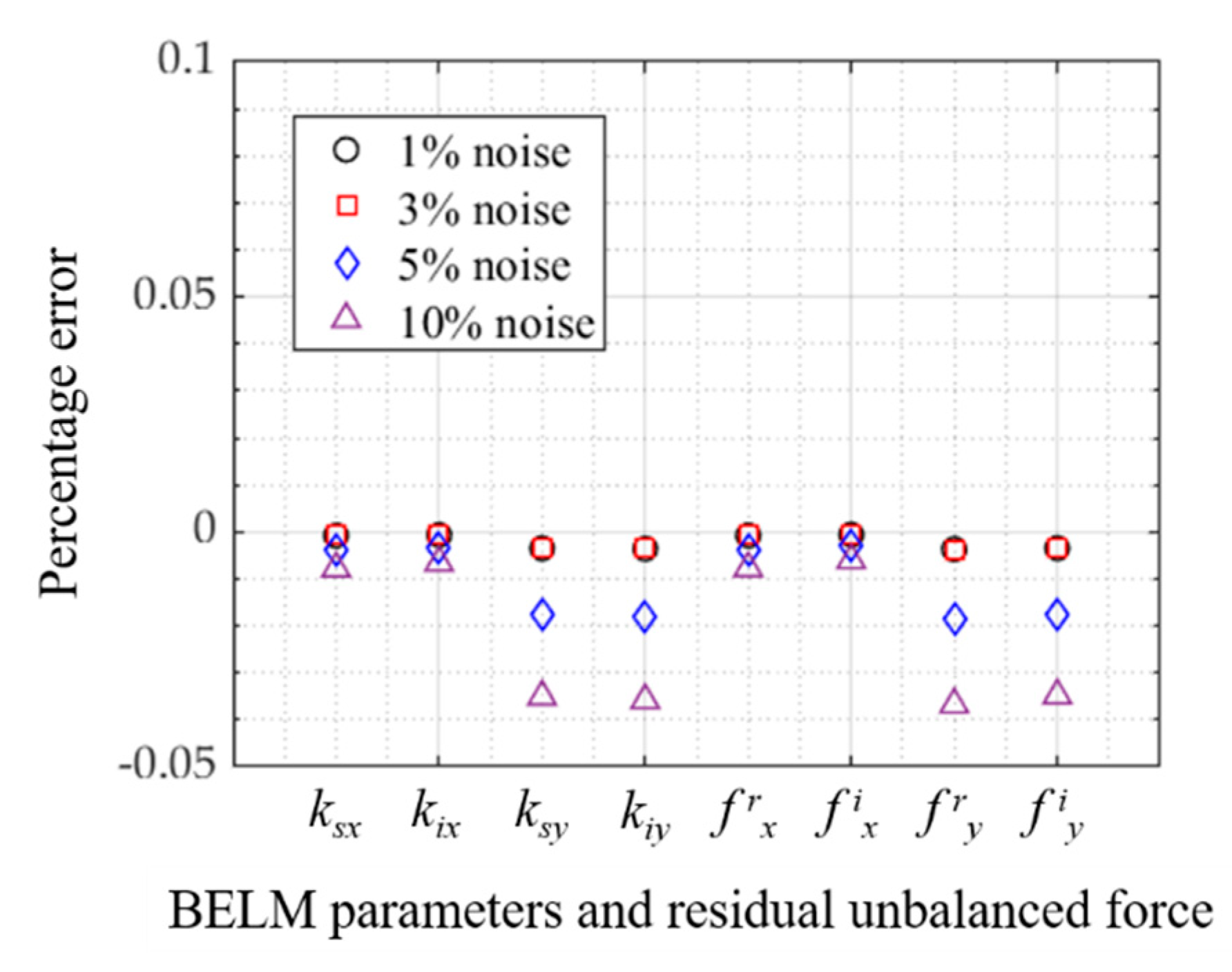
4. Numerical Simulations
5. Experimental Identification and Verification
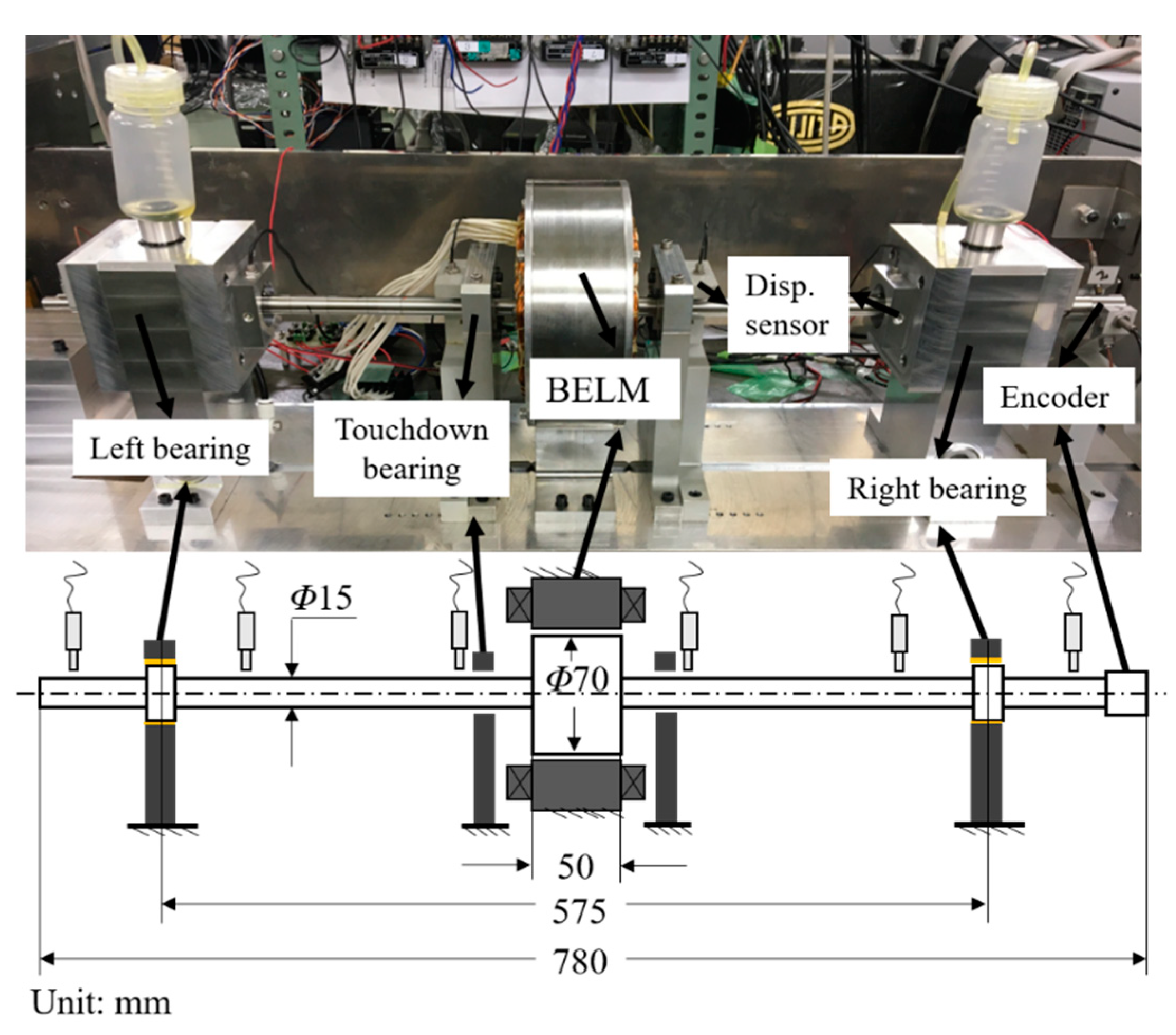
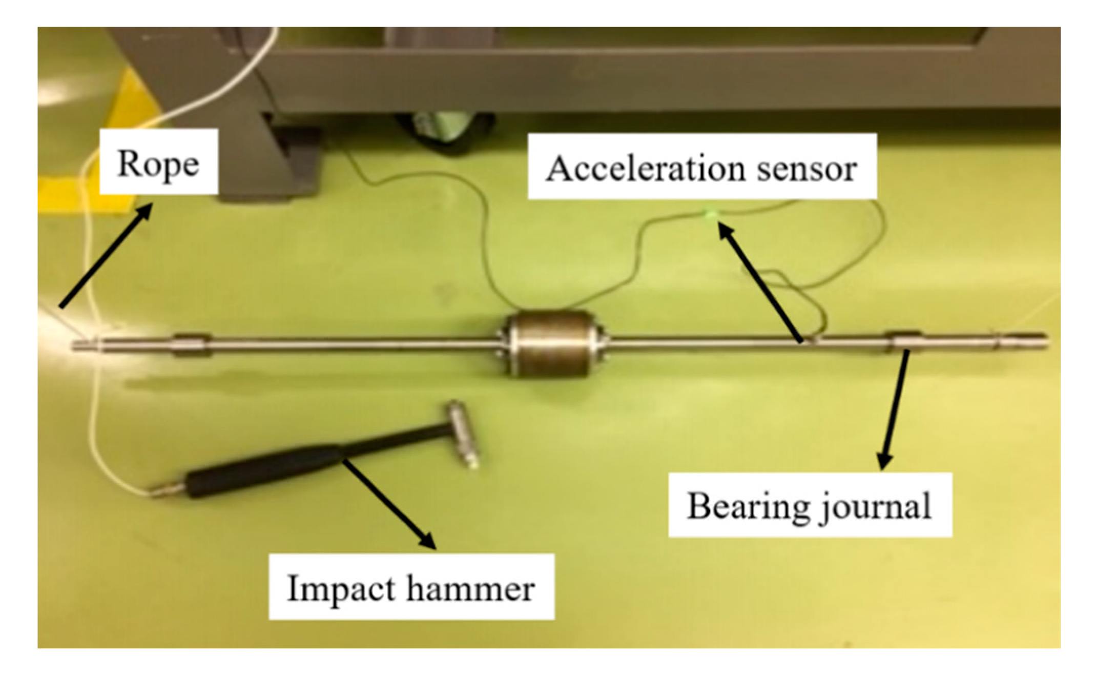
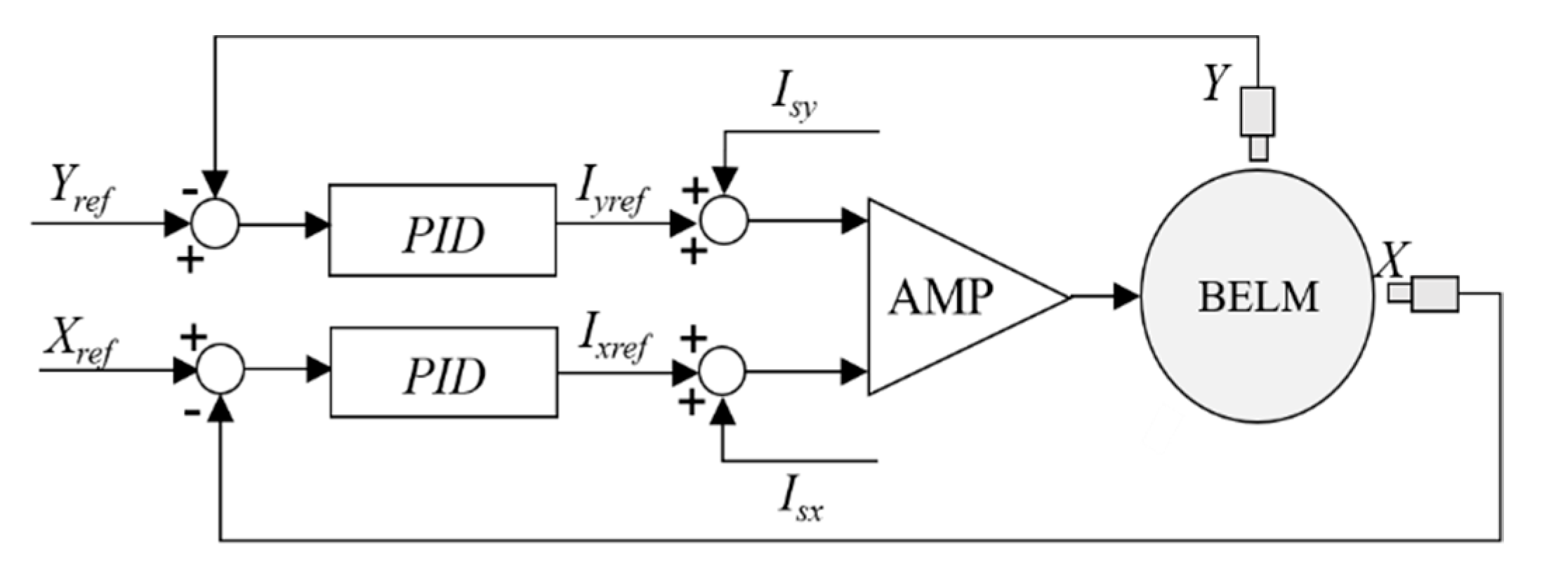
5.1. Experiment Description
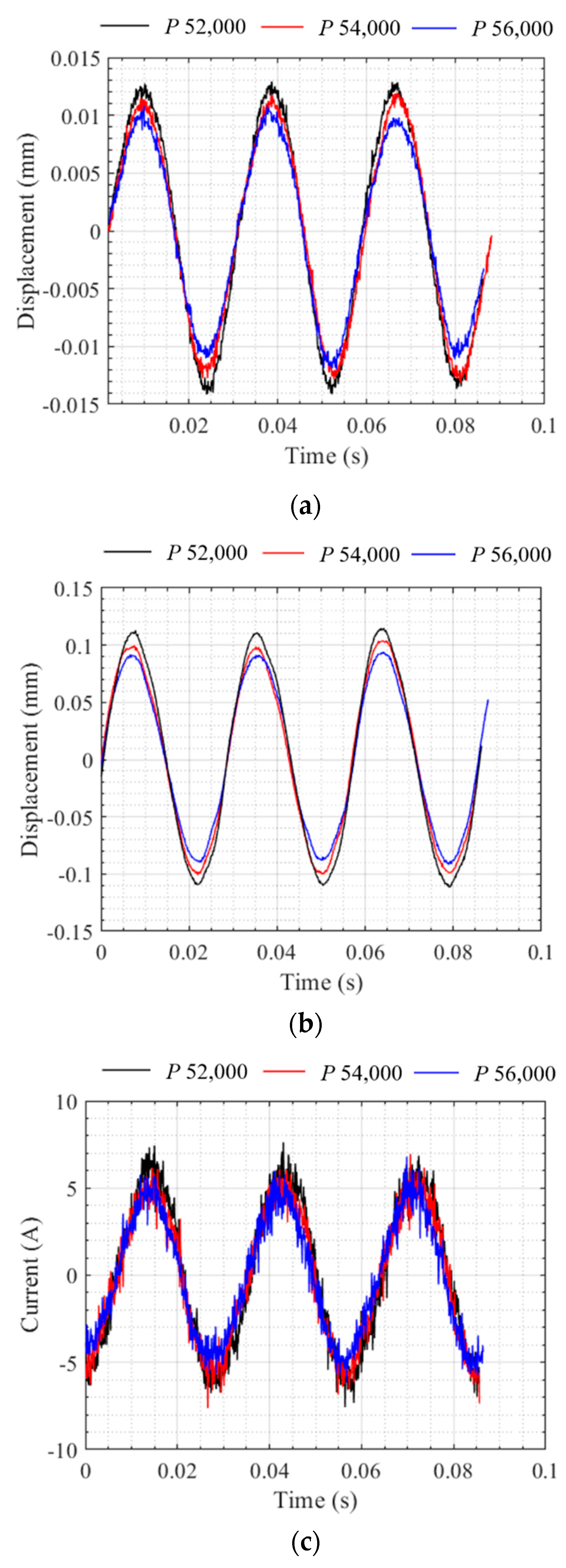
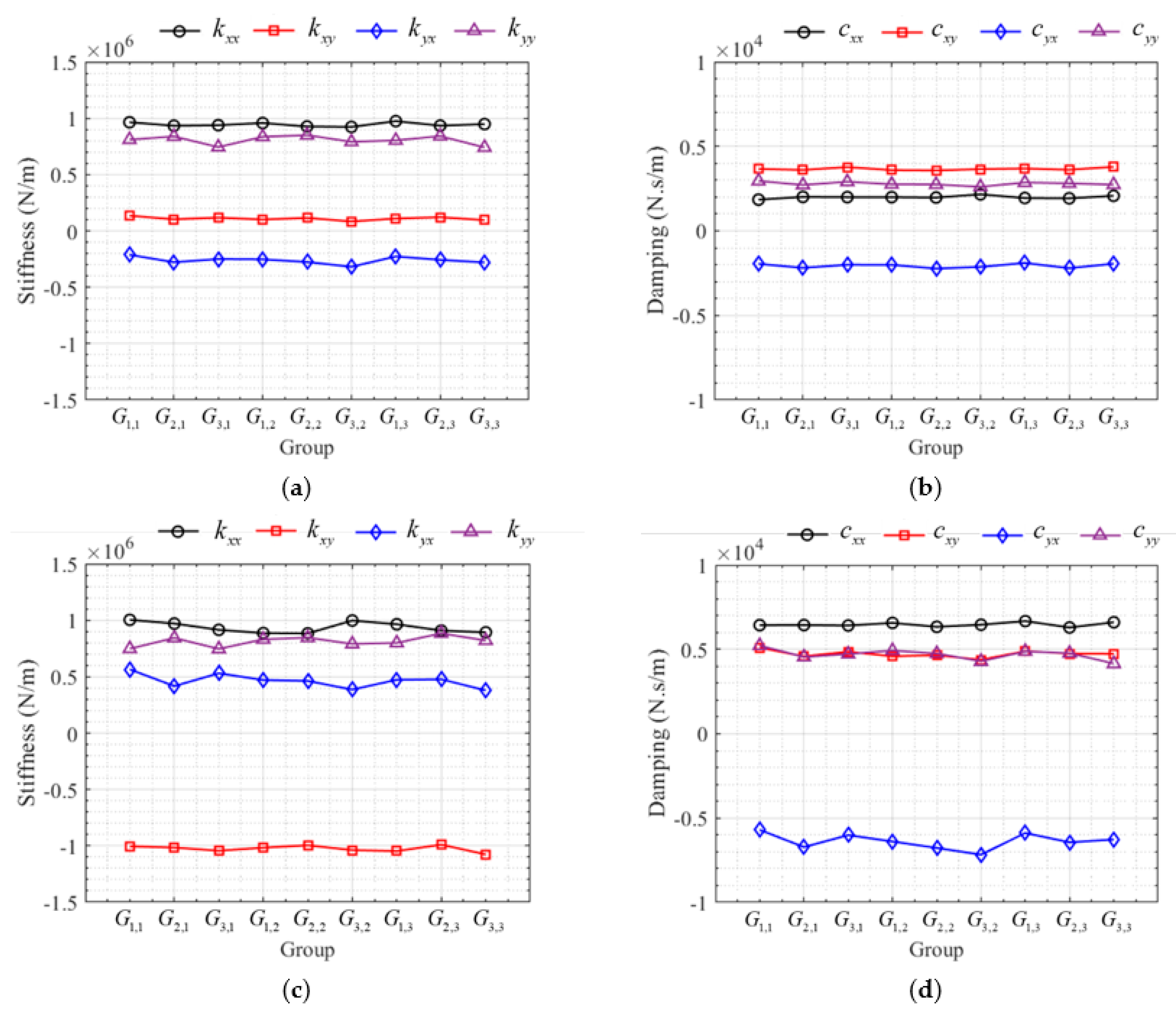
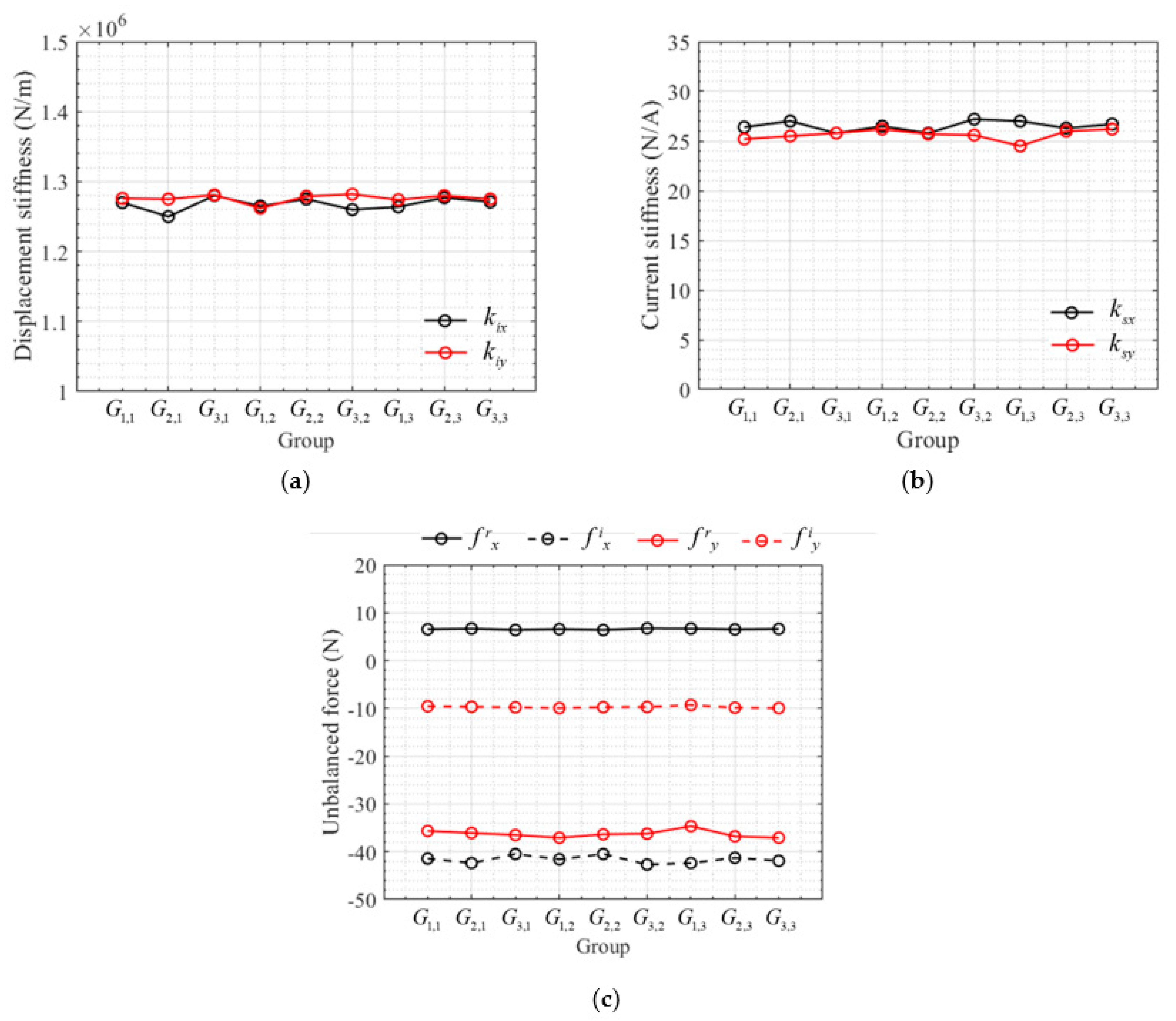
5.2. Experiment Results
5.3. Verification of the Results
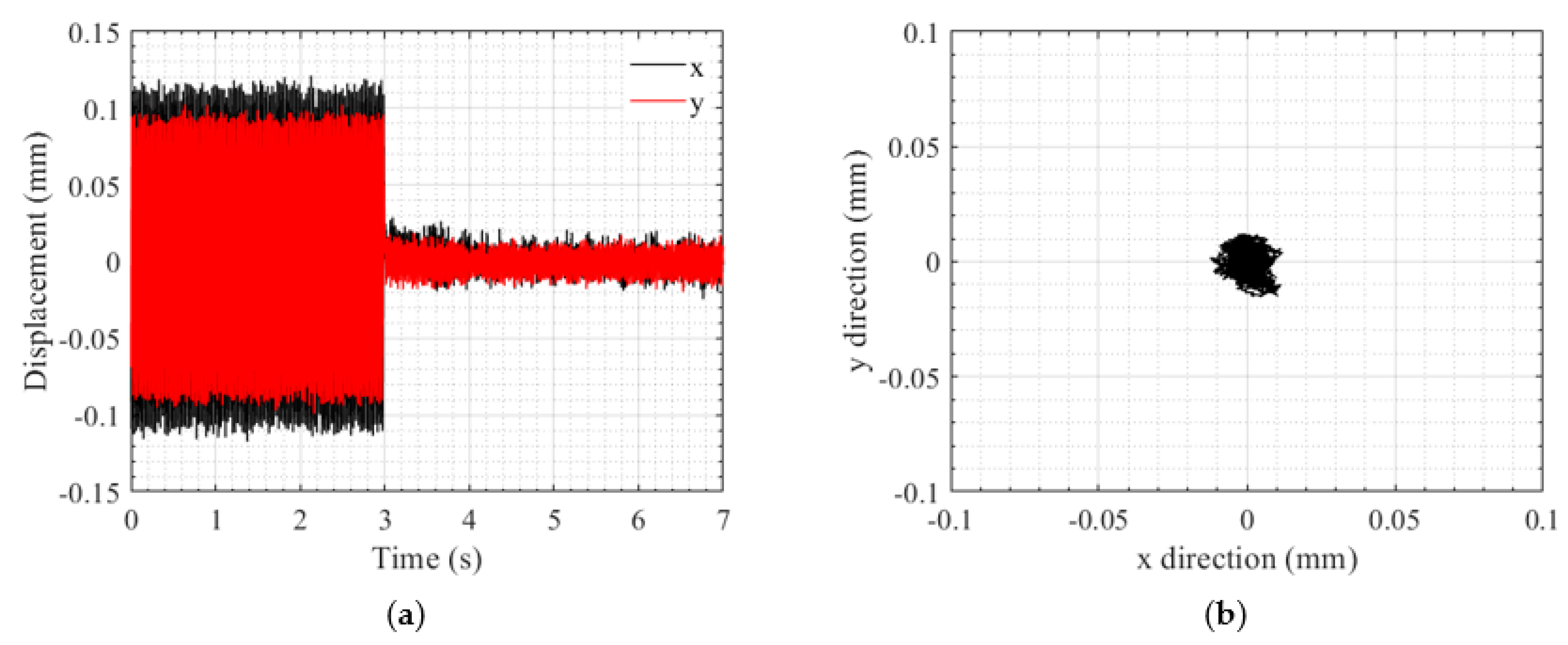
5.3.1. Vibration Suppression Test
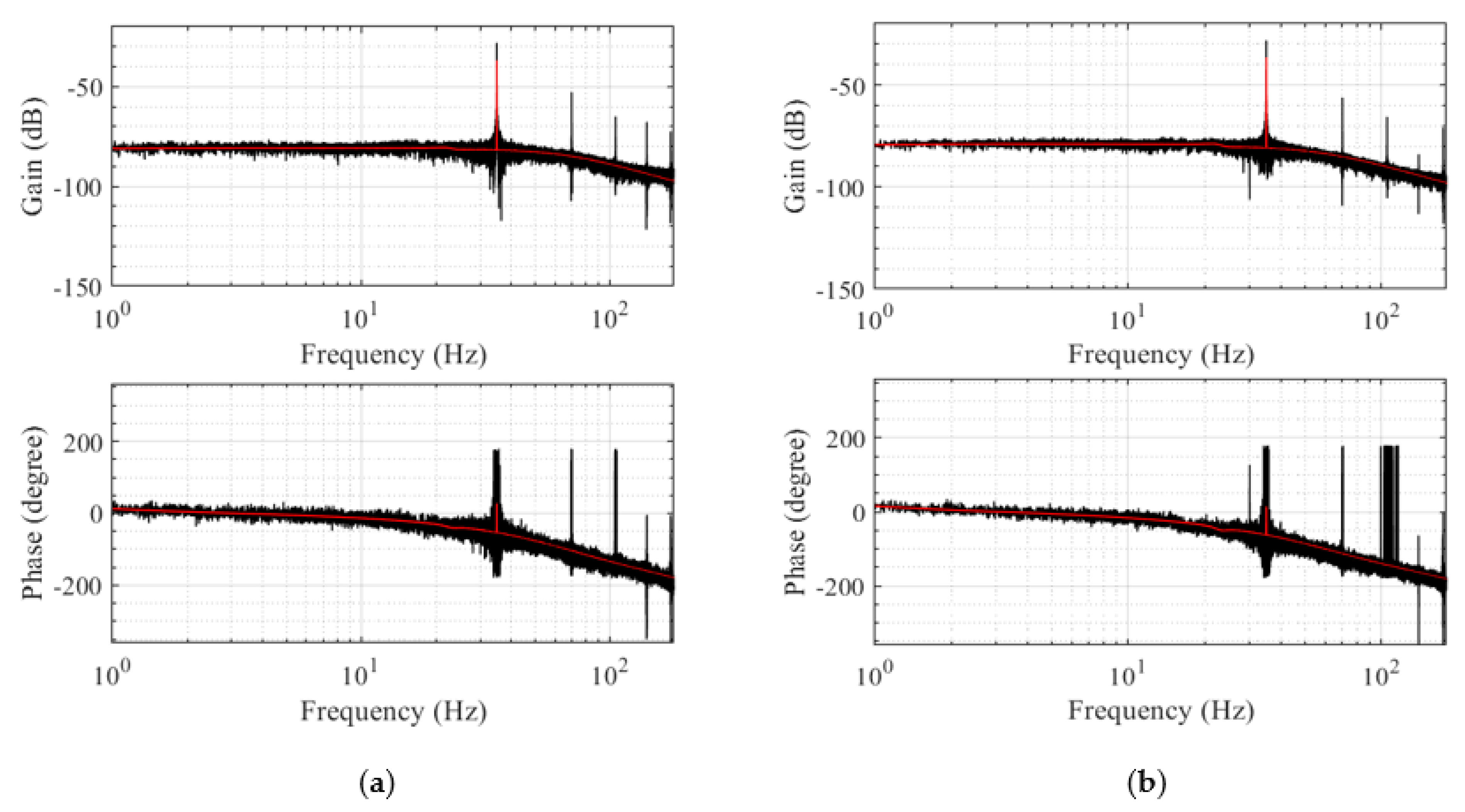
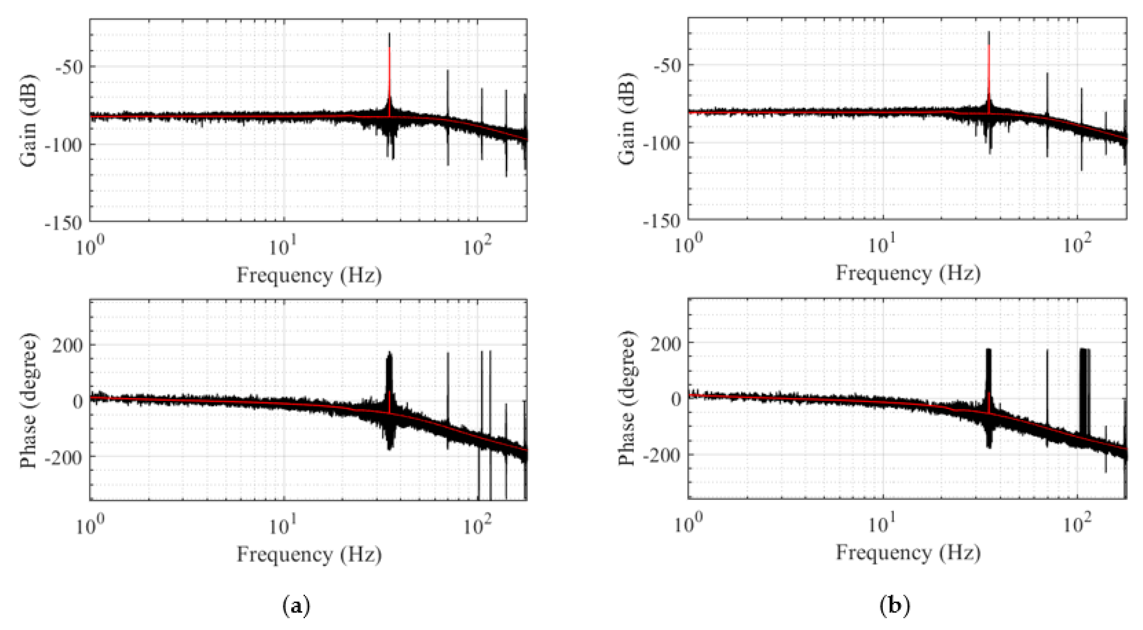
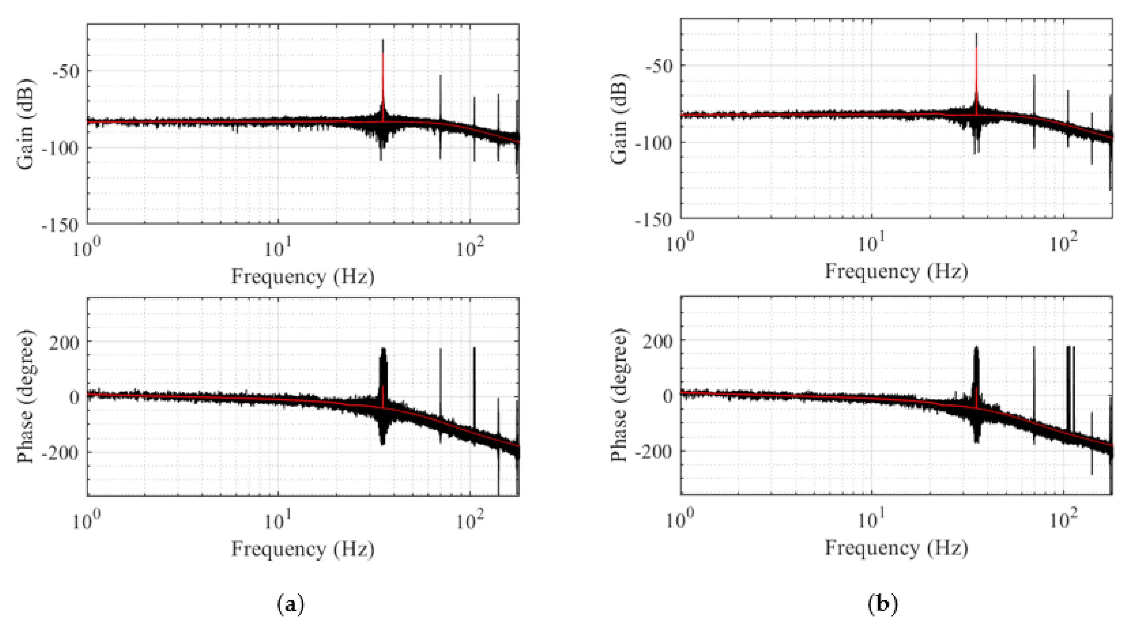
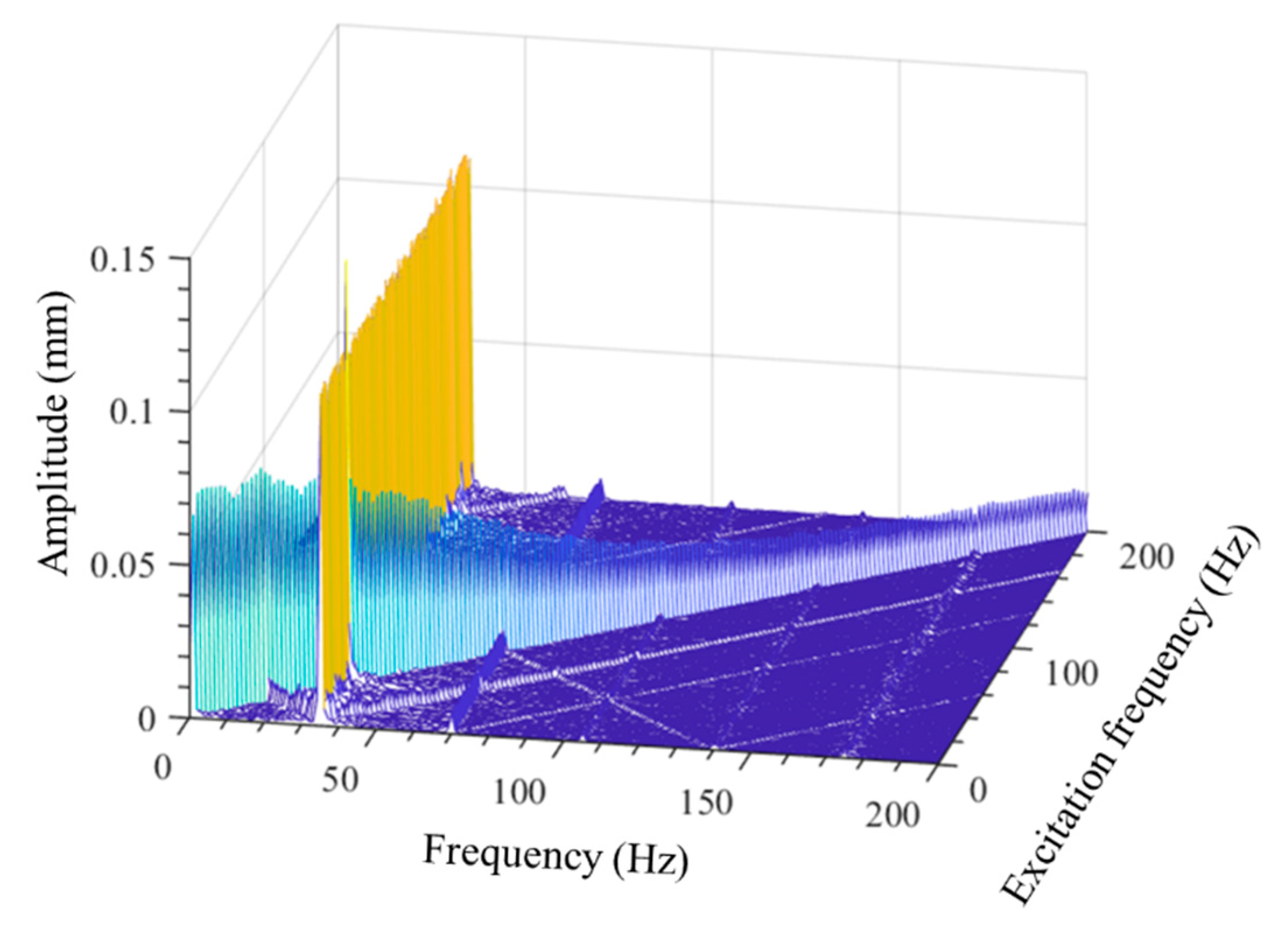
5.3.2. Frequency Response Characteristics
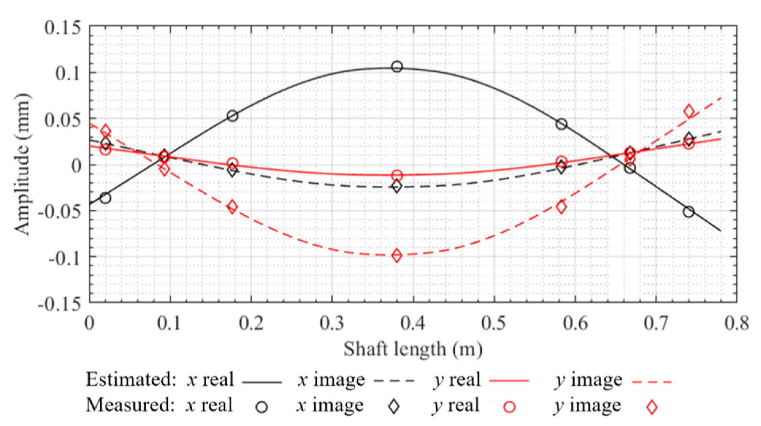
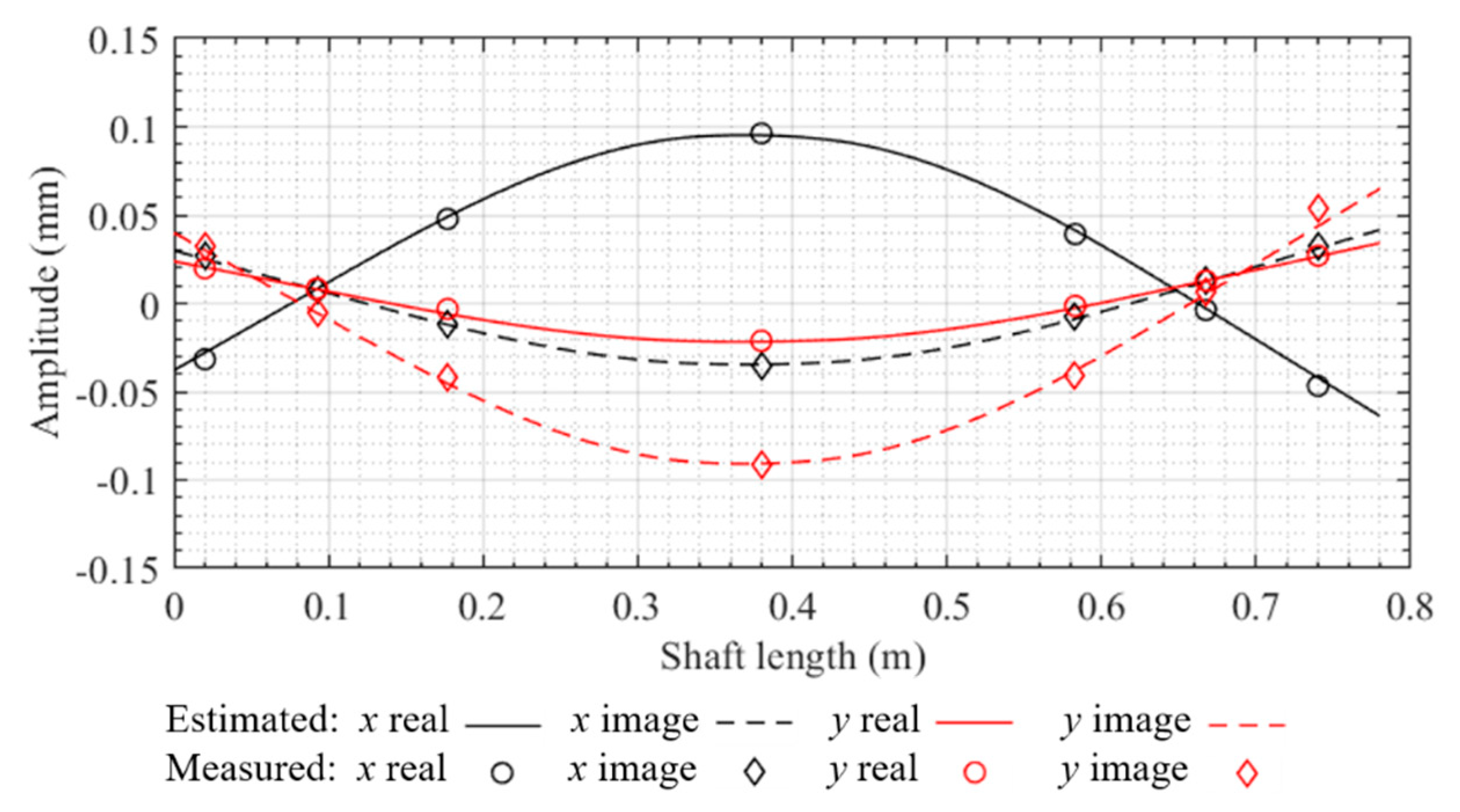
5.3.3. Unbalanced Response
6. Conclusions
Author Contributions
Funding
Institutional Review Board Statement
Informed Consent Statement
Data Availability Statement
Acknowledgments
Conflicts of Interest
References
- Muszynska, A. Whirl and whip—rotor/bearing stability problems. J. Sound Vib. 1986, 110, 443–462. [Google Scholar] [CrossRef] [Green Version]
- EI-Shafei, A.; Tawfick, S.H.; Raafat, M.S.; Aziz, G.M. Some Experiments on Oil Whirl and Oil Whip. Turbo Expo Power Land Sea Air 2004, 41715, 701–710. [Google Scholar]
- Kasarda, M.E.F.; Mendoza, H.; Kirk, R.G.; Wicks, A. Reduction of Subsynchronous Vibrations in a Single Disk Rotor Using An Active Magnetic Damper. Mech. Res. Commun. 2004, 31, 689–695. [Google Scholar] [CrossRef]
- Kasarda, M.E.F.; Allaire, P.E.; Humphris, R.R.; Barrett, L.E. A Magnetic Damper for First-Mode Vibration Reduction in Multimass Flexible Rotors. J. Eng. Gas Turbines Power 1990, 112, 463–469. [Google Scholar] [CrossRef] [Green Version]
- Tsunoda, W.; Chiba, A.; Shinshi, T. Suppression of self-excited vibration caused by oil film bearing using bearingless motor. In Proceedings of the IEEE International Electric Machines and Drives Conference, Miami, FL, USA, 21–24 May 2017. [Google Scholar]
- Tsunoda, W.; Chiba, A.; Shinshi, T. Vibration control for a rotor supported by oil-film bearings using a bearingless motor. IEEE/ASME Trans. Mechatron. 2019, 24, 1368–1375. [Google Scholar] [CrossRef]
- Tsunoda, W.; Chiba, A.; Shinshi, T. Combination of Oil Film Bearing and Bearingless Motor for High Load Capacity and Stable Rotation. In Proceedings of the IEEE 27th International Symposium on Industrial Electronics, Cairns, Australia, 13–15 June 2018. [Google Scholar]
- Tiwari, R.; Lees, A.W.; Friswell, M.I. Identification of dynamic bearing parameters: A review. Shock. Vib. Dig. 2004, 36, 99–124. [Google Scholar] [CrossRef]
- Goodwin, M.J. Experimental Techniques for Bearing Impedance Measurement. J. Manuf. Sci. Eng. 1991, 113, 335–342. [Google Scholar] [CrossRef]
- Tiwari, R.; Avinash, C. Identification of bearing dynamic parameters and unbalance states in a flexible rotor system fully levitated on active magnetic bearings. Mechatronics 2014, 24, 274–286. [Google Scholar] [CrossRef]
- Myllerup, C.M.; Tonnesen, J.; Lund, J.W. On the discrepancies between experiment and theory for a cylindrical fluid-film journal bearing considering steady-state and dynamic characteristics. In Proceedings of the IMechE Vibrations in Rotating Machinery Conference, Bath, UK, 7–10 September 1992; 1992; pp. 1–6. [Google Scholar]
- Mitchell, J.R.; Holmes, R.; Ballegooyen, H.V. Paper 2: Experimental Determination of a Bearing Oil-Film Stiffness. Proc. Inst. Mech. Eng. Conf. Proc. 1965, 180, 90–96. [Google Scholar] [CrossRef]
- Childs, D.; Joel, H. Static performance characteristics and rotordynamic coefficients for a four-pad ball-in-socket tilting pad journal bearing. J. Eng. Gas Turbines Power 2009, 131, 062502. [Google Scholar] [CrossRef]
- Jiang, G.; Hu, H.; Xu, W.; Jin, Z.; Xie, Y. Identification of oil film coefficients of large journal bearings on a full-scale journal bearing test rig. Tribol. Int. 1997, 30, 789–793. [Google Scholar] [CrossRef]
- De Santiago, O.C.; San Andrés, L. Field methods for identification of bearing support parameters part II: Identification from rotor dynamic response due to imbalances. J. Eng. Gas Turbines Power 2007, 129, 213–219. [Google Scholar] [CrossRef]
- De Santiago, O.C.; San Andrés, L. Field methods for identification of bearing support parameters part I: Identification from transient rotor dynamic response due to impacts. J. Eng. Gas Turbines Power 2007, 129, 205–212. [Google Scholar] [CrossRef]
- Tiwari, R.; Lees, A.; Friswell, M. Identification of speed-dependent bearing parameters. J. Sound Vib. 2002, 254, 967–986. [Google Scholar] [CrossRef] [Green Version]
- San Andrés, L.; De Santiago, O.C. Identification of bearing force coefficients from measurements of imbalance response of a flexible rotor. ASME Turbo Expo 2004 Power Land Sea Air 2004, 41677, 843–850. [Google Scholar]
- Zhou, J.; Di, L.; Cheng, C.; Xu, Y.; Lin, Z. A rotor unbalance response based approach to the identification of the closed-loop stiffness and damping coefficients of active magnetic bearings. Mech. Syst. Signal Process. 2016, 66, 665–678. [Google Scholar] [CrossRef]
- Matsubara, A.; Tsujimoto, S.; Kono, D. Evaluation of dynamic stiffness of machine tool spindle by non-contact excitation tests. CIRP Ann. 2015, 64, 365–368. [Google Scholar] [CrossRef]
- Arumugam, P.; Swarnamani, S.; Prabhu, B.S. Experimental Identification of Linearized Oil Film Coefficients of Cylindrical and Tilting Pad Bearings. J. Eng. Gas Turbines Power 1995, 117, 593–599. [Google Scholar] [CrossRef]
- Wang, W.; Li, Q.; Gao, J.; Yao, J.; Allaire, P. An identification method for damping ratio in rotor systems. Mech. Syst. Signal Process. 2016, 68, 536–554. [Google Scholar] [CrossRef]
- Li, Q.; Wang, W.; Weaver, B.; Wood, H. Model-Based Interpolation-Iteration Method for Bearing Coefficients Identification of Operating Flexible Rotor-Bearing System. Int. J. Mech. Sci. 2017, 131, 471–497. [Google Scholar] [CrossRef]
- Xu, Y.; Zhou, J.; Lin, Z.; Jin, C. Identification of dynamic parameters of active magnetic bearings in a flexible rotor system considering residual unbalances. Mechatronics 2018, 49, 46–55. [Google Scholar] [CrossRef]


| Components | Parameters | Values |
|---|---|---|
| Length | 780 mm | |
| Diameter | Φ15 mm | |
| Shaft | Young’s modulus | 2.05 × 10¹¹ N/m2 |
| Mass density | 7850 kg/m3 | |
| Poisson’s ratio | 0.29 | |
| Oil-film bearing | Length | 25 mm |
| Diameter | 25 mm | |
| Motor | Rotor length | 50 mm |
| Rotor diameter | 70 mm |
| Directions | Parameters | First Set | Second Set |
|---|---|---|---|
| x-direction | Proportional (P) | 52,000 | 54,000 |
| Integral (I) | 17,500 | 17,500 | |
| Derivative (D) | 60 | 60 | |
| Filter coefficient (Nf) | 12,560 | 12,560 | |
| y-direction | Proportional (P) | 54,000 | 52,000 |
| Integral (I) | 17,500 | 17,500 | |
| Derivative (D) | 60 | 60 | |
| Filter coefficient (Nf) | 12,560 | 12,560 |
| Parameters | Bearing 1 | Bearing 2 | |||
|---|---|---|---|---|---|
| Assumed | Estimated | Assumed | Estimated | ||
| Stiffness (N/m) | kxx | 1 × 10⁵ | 1.000 × 10⁵ | 1.4 × 10⁵ | 1.399 × 10⁵ |
| kxy | 1.2 × 10⁵ | 1.200 × 10⁵ | 1.6 × 10⁵ | 1.599 × 10⁵ | |
| kyx | 1.4 × 10⁵ | 1.399 × 10⁵ | 1.8 × 10⁵ | 1.800 × 10⁵ | |
| kyy | 1.8 × 10⁵ | 1.799 × 10⁵ | 2.0 × 10⁵ | 2.000 × 10⁵ | |
| Damping (N.s/m) | cxx | 1000 | 1000.000 | 1200 | 1199.999 |
| cxy | 800 | 800.000 | 500 | 499.999 | |
| cyx | 600 | 599.999 | 600 | 600.000 | |
| cyy | 2000 | 1999.999 | 1500 | 1500.000 | |
| Directions | Parameters | Assumed | Estimated |
|---|---|---|---|
| x-direction | ksx (N/m) | 8.62 × 10⁵ | 8.619 × 10⁵ |
| kix (N/A) | 28 | 29.999 | |
| f rx (N) | 34.64 | 34.641 | |
| f ix (N) | −20 | −20.000 | |
| y-direction | ksy (N/m) | 8.72 × 10⁵ | 8.719 × 10⁵ |
| kiy (N/A) | 28.8 | 28.799 | |
| f ry (N) | 25 | 24.999 | |
| f iy (N) | 43.30 | 43.301 |
| Modal | Measured Frequency | Calculated Frequency | Error |
|---|---|---|---|
| 1 | 83.3 Hz | 82.9 Hz | −0.48% |
| 3 | 510.8 Hz | 507.5 Hz | −0.64% |
| 4 | 770.5 Hz | 756.5 Hz | −1.82% |
| Directions | Group1 (G1) | Group2 (G2) | Group3 (G3) | |||
|---|---|---|---|---|---|---|
| Set 1 | Set 2 | Set 1 | Set 2 | Set 1 | Set 2 | |
| x | 52,000 | 54,000 | 52,000 | 56,000 | 54,000 | 56,000 |
| y | 54,000 | 52,000 | 56,000 | 52,000 | 56,000 | 54,000 |
Publisher’s Note: MDPI stays neutral with regard to jurisdictional claims in published maps and institutional affiliations. |
© 2021 by the authors. Licensee MDPI, Basel, Switzerland. This article is an open access article distributed under the terms and conditions of the Creative Commons Attribution (CC BY) license (https://creativecommons.org/licenses/by/4.0/).
Share and Cite
Chen, Y.; Yang, R.; Sugita, N.; Mao, J.; Shinshi, T. Identification of Bearing Dynamic Parameters and Unbalanced Forces in a Flexible Rotor System Supported by Oil-Film Bearings and Active Magnetic Devices. Actuators 2021, 10, 216. https://0-doi-org.brum.beds.ac.uk/10.3390/act10090216
Chen Y, Yang R, Sugita N, Mao J, Shinshi T. Identification of Bearing Dynamic Parameters and Unbalanced Forces in a Flexible Rotor System Supported by Oil-Film Bearings and Active Magnetic Devices. Actuators. 2021; 10(9):216. https://0-doi-org.brum.beds.ac.uk/10.3390/act10090216
Chicago/Turabian StyleChen, Yinsi, Ren Yang, Naohiro Sugita, Junhong Mao, and Tadahiko Shinshi. 2021. "Identification of Bearing Dynamic Parameters and Unbalanced Forces in a Flexible Rotor System Supported by Oil-Film Bearings and Active Magnetic Devices" Actuators 10, no. 9: 216. https://0-doi-org.brum.beds.ac.uk/10.3390/act10090216