
Port-Hamiltonian Modeling and IDA-PBC Control of an IPMC-Actuated Flexible Beam


1
Zhejiang University City College, Hangzhou 310015, China
2
College of Electrical Engneeering, Zhejiang University, Hangzhou 310027, China
3
FEMTO-ST, University Bourgogne Franche-Comté, CNRS, 24 rue Savary, F25000 Besançon, France
4
(CNBM) Intellgent Automation Research Institute for Light Industry, Hangzhou 310027, China
*
Author to whom correspondence should be addressed.
Actuators 2021, 10(9), 236; https://0-doi-org.brum.beds.ac.uk/10.3390/act10090236
Submission received: 2 August 2021
/
Revised: 6 September 2021
/
Accepted: 8 September 2021
/
Published: 14 September 2021
(This article belongs to the Special Issue Actuators in Robotic Control)
Abstract
:In this paper, the infinite-dimensional port-Hamiltonian modelling and control problem of a flexible beam actuated using ionic polymer metal composite (IPMC) actuators is investigated. The port-Hamiltonian framework is used to propose an interconnected control model of the mechanical flexible beam and the IPMC actuator. The mechanical flexible dynamic is modelled as a Timoshenko beam, and the electric dynamics of the IPMCs are considered in the model. Furthermore, a passivity-based control-strategy is used to obtain the desired configuration of the proposed interconnected system, and the closed-loop stability is analyzed using the early lumped approach. Lastly, numerical simulations and experimental results are presented to validate the proposed model and the effectiveness of the proposed control law.
1. Introduction
Minimally invasive surgery with the application of different types of endoscopes has been developed in recent years. In order to avoid irreversible damage and to alleviate the suffering of patients due to the complexity and fragility of the human body, providing additional degrees of freedom using embedded actuators on endoscopes has garnered particular attention over the last decade with the development of smart materials and manufacturing techniques. A micro-endoscope model for endonasal skull base surgery was proposed in [1], in which ionic polymer metal composites (IPMCs) were used to actuate the bending movement of the micro-endoscope. IPMCs are widely used for their attractive properties: ease of fabrication, fast response, large strain, and low actuation voltage [2].
An IPMC-actuated flexible structure for medical applications is proposed in this paper. The mechanical structure of the endoscope consists primarily of a polyethylene-made compliant inner tube. In this paper, we consider the endoscope inner tube as a flexible beam using Timoshenko beam theory. Despite its attractive properties, the modelling and control of an IPMC actuator are challenging due to its complexity and the flexibility of its structure. The physical properties of IPMC-actuated endoscopes result in a complex multi-physical modelling and non-linear infinite dimensional control problem. This motivates us to use the port-Hamiltonian framework to address the modelling and control of an actuated endoscope model. The port-Hamiltonian system (PHS) formalism is based on the energy conservation and dissipation of a system and on energy exchanges between the components of complex physical systems. Different components of the system are interconnected through energy ports in a straight-forward and clear manner. The port-Hamiltonian formulation was introduced for finite-dimensional systems in different physical nature systems [3,4,5,6] and has been further extended to infinite-dimensional systems described by partial differential equations [7,8,9].
The port-Hamiltonian formulation of IPMC actuators with different assumptions was proposed in [10,11] considering multi-scale phenomena. In the paper, an IPMC-actuated endoscope system is described by a coupled system of sets of partial differential equations (PDEs) interconnected with an ordinary differential equation (ODE). Different physical parts of the system are considered interconnected by the port-Hamiltonian formalism through the energy change ports. All of the physical natures of the components, such as the beam’s flexibility and the physical propriety of IPMC actuators, are considered in this formulation.
Furthermore, the port-Hamiltonian framework was shown to be able to handle passivity-based control with a physical interpretation for finite- and infinite-dimensional systems [12,13]. Many studies have been dedicated to the interconnection and damping assignment passivity-based control (IDA-PBC) for physical systems [14,15].
Interconnected rigid links are used to model a flexible structure using the port-Hamiltonian approach in [16]. The proposed model is a non-linear lumped parameter system. However, many rigid links are needed to represent the high-frequency vibration of the flexible structure. The model proposed in [16] becomes very complex when the number of links increases and is impractical for control design. In [17], a passive linear quadratic gaussian (LQG) controller and damping injection are used to achieve the desired configuration of the flexible structure system, where the simulation results of a passive LQG controller on a mono-IPMC-actuated flexible structure are presented.
The main contribution of this paper is that a distributed parameter interconnected model with a multi-IPMC actuator is investigated to deal with the flexible nature of the structure. The distributed Timoshenko beam model is used to deal with the flexible behaviour appropriately. Furthermore, IDA-PBC feedback control is proposed for the model and we show the asymptotic stability of the closed-loop system. Moreover, control law is implemented in the experimental setup to validate the effectiveness of the proposed method in the mono-actuated case. We define an integral action conserving the Hamiltonian nature to account for steady errors due to an activity reduction of the IPMC actuator. In the multi-actuated case, the simulation results illustrate that the proposed control law allows us to shape the flexible beam into our desired shape.
The paper is organized as follows: In Section 2, we present the port-Hamiltonian formulation of the IPMC-actuated flexible beam system modelled by sets of partial differential equations (PDEs) and an ordinary differential equation (ODE). In Section 3, we design an IDA-PBC-based finite-dimensional control law to improve the flexible beam system performance. In Section 4, we give some simulation results, and an experimental validation on a platform setup is presented to validate the proposed control law. In Section 5, some concluding remarks and perspectives are given.
2. Port-Hamiltonian Formulation for IPMC Actuated Flexible Beam
We consider the modelling of an IPMC-actuated endoscope (Figure 1) using the port-Hamiltonian formulation.
Several IPMC actuator patches are attached to a polyethylene-made compliant inner tube. With the voltages applied across the IPMC actuators, torques are generated to control its configuration. The distributed Timoshenko beam model (PDE) is used to describe the mechanical beam behavior of the endoscope. A lumped parameter RLC model (ODE) is presented to describe the interface/polymer diffusion dynamics of the IPMC actuator. Moreover, a power-preserving interconnection is used to obtain the coupled PDE-ODE model to describe the overall dynamics of the system.
2.1. Flexible Beam with Distributed Control
The control objective is to shape the flexible beam into a desired configuration using the IPMC patches. The patches are actuated by the distributed bending moment, denoted by , induced by the voltage applied. The dynamics of the Timoshenko beam [18,19] with distributed input and power conjugate output are given as follows:
with a first-order skewed symmetric differential operator on the state space and with
The total mechanical energy of the flexible beam is considered Hamiltonian:
where is the transverse displacement and is the beam rotation angle of the beam. The coefficients and are the mass per unit length and the mass moment of inertia of the cross-section of the beams, respectively. E, I, and K are Young’s modulus, the moment of inertia of the cross-section, and the shear modulus, respectively.
The state variable vector of the system is defined from the Hamiltonian function considering the mechanical energy: and , defined by the potential energy, are shear and bending strain, respectively. and are the transverse and rotational momenta for , , which correspond to the kinetic energy.
Hence, the Hamiltonian function is as follows:
with the operator .
The dissipation operator is defined as follows:
with the translational and angular viscous fraction constants and .
As shown in Figure 1, the IPMC-actuated structure is fixed on a base (This base can be fixed or can be moved forward and backward by an electric motor. However, in this work, we consider the base as fixed, and only the stabilization and shape control problem of the flexible structure are investigated), and the tip side is controlled. In this condition, we consider that, on fixed side a, the velocity and the angular velocity are null, while on free side b, the strain and the moment are zero. Thus, we consider the boundary conditions as the boundary input,
and the boundary power conjugate outputs are as follows:
We define ( denotes an i-dimensional complex space) as the distributed input map; as the distributed moment density applied to the beam, which corresponds to the torque generated by the IPMC patches in our case; and as the power conjugated output of , i.e., the distributed angular velocity. The distributed input operator is given by on the ith spatial section . We note that if and elsewhere and that if m actuators are glued onto the beam. We consider the angular velocity mean values as the output in the same intervals . Thus, the distributed input is given by the following:
where , , and . The output variable is the power conjugate variable of the input. Hence, one can compute the energy balance of the system as follows: .
2.2. The IPMC Actuator Model
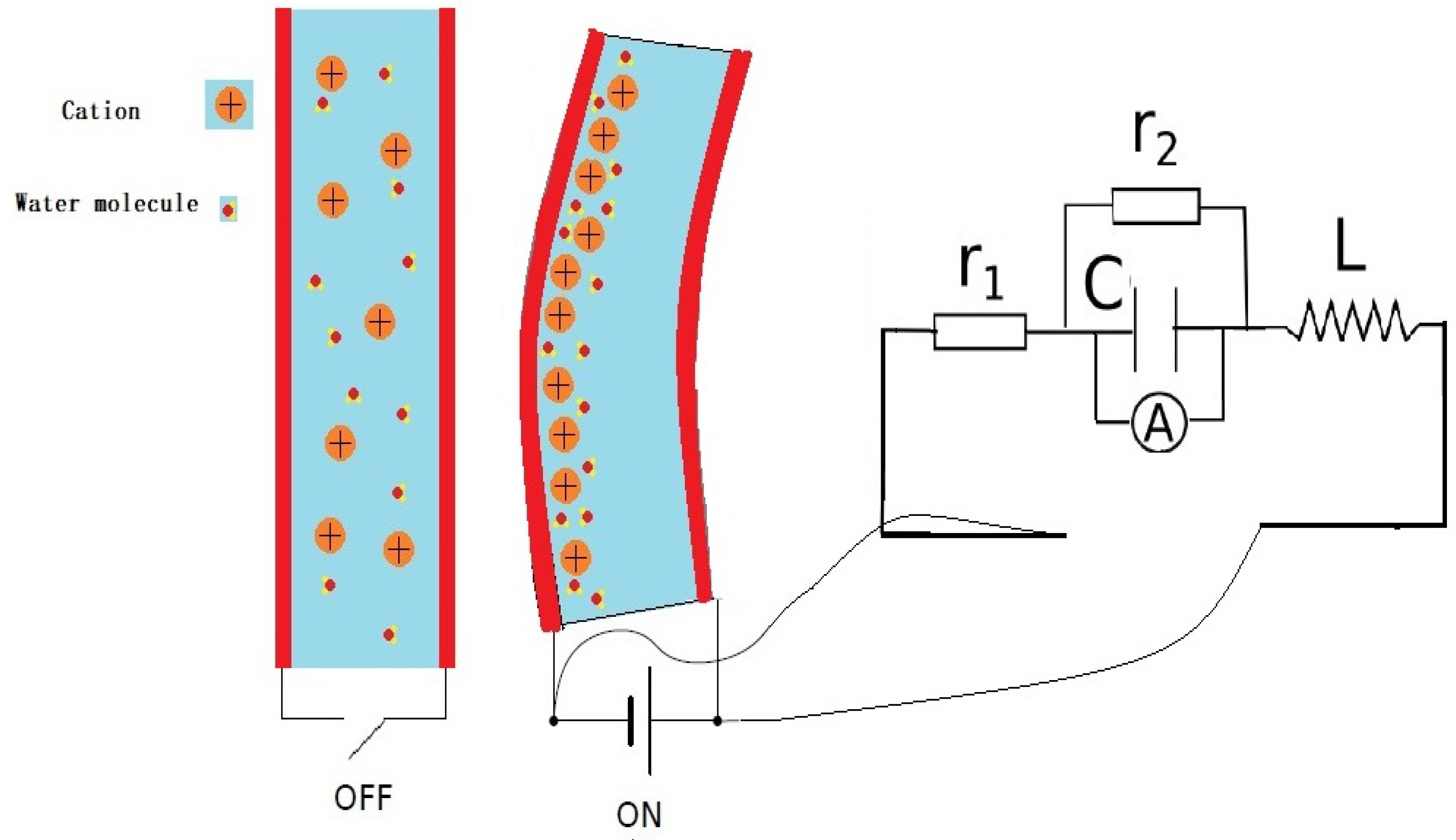
The dynamics of IPMCs are modeled as the coupling of three different physical contributions: the electric part from the electric double layer between the electrodes, the diffusion phenomena of water and cations, and the mechanical contribution. The physical deformation induced by the applied voltage is primarily caused by the diffusion of a cation flux in the membrane between the electrodes (see Figure 2) [2]: when a voltage source is applied to the edge of the IPMC actuator, the potential difference in the electric double layer transfers the cations and water molecules to one side of the electrode in the polymer gel. This transfer causes the gel to swell and a bending moment to be applied to the mechanical system.
In this work, the interconnection between the IPMC actuator and the beam is assumed to be perfect. Thus, we consider that the mechanical contribution of the IPMC actuator is combined with the beam as part of the Timoshenko beam model. For control purposes, a simplified lumped RLC model [20] is used to model the electric dynamics of the IPMC. The torque generated by the IPMC patch is proportional to the voltage applied.
with the state variables vector , where Q is the charge of the capacitor and is electric flux for each IPMC equivalent electrical model:
The dissipation matrices and of the IPMC actuator are defined by the resistances and of each equivalent IPMC model, where :
The total electrical energy of the m IPMC actuators is considered to be the Hamiltonian of the actuator:
where we define the capacitance matrix and the inductance matrix as follows:
The input variables u and are the voltage applied on the two electrodes of the IPMC actuator and the current input due to mechanical deflection of the actuator structure, respectively. Their power-conjugated outputs are , the current over the inductance, and , the voltage of the capacitor.
We define the interconnection relation between the IPMC actuator systems and the flexible beam system:
The capacitor voltage provides the bending moments of each actuator with a constant factor . On the other hand, we assume that the power exchange between the flexible beam and IPMC actuators is perfect, i.e., the interconnection is power-preserving. Consequently, the beam movement generates current applied to the capacitor.
Considering the IPMC actuator Equation (8) and the flexible Equation (1), the port-Hamiltonian formulation of the complete system is defined by the following:
where , ,
with the appropriate dimension zero matrices 0. The state space of the coupled system is .
Due to the energy-preserving interconnections, the total energy of the system is the sum of the Hamiltonian function of the two coupled sun-systems:
where the energy operator of the coupled PDE-ODE system is as follows:
For simulation and control design purposes, the PDE-ODE coupled system (12) needs to be discretized. At the same time, in order to use the passivity-based control law, the port-Hamiltonian structure should be preserved. To this end, the structure-preserving Mixte finite element [21] discretization method is employed to discretize the system (12), which leads to a finite dimensional system as follows:
where , , , and are the discretized state variables of the infinite dimensional model of a flexible beam and where the matrices T and S are the discretization of the differential operator and the coupling term of the PHS Timoshenko beam presented, which are written as ,
Remark 1.
The discritization method used in this paper is the mixed finite element method used to preserve the port-Hamiltonian structure such that we can use passivity-based control using the discretized finite dimensional system (15). We can also use other structure-preserving methods to discretize the system (12), such as the pseudo-spectral method [22], the finite difference method on a staggered grid [23], and the finite volume structure-preserving discretization method [24]. A literature review on distributed parameter port-Hamiltonian systems and their discretization methods can be found in [25].
3. Control Design via IDA-PBC
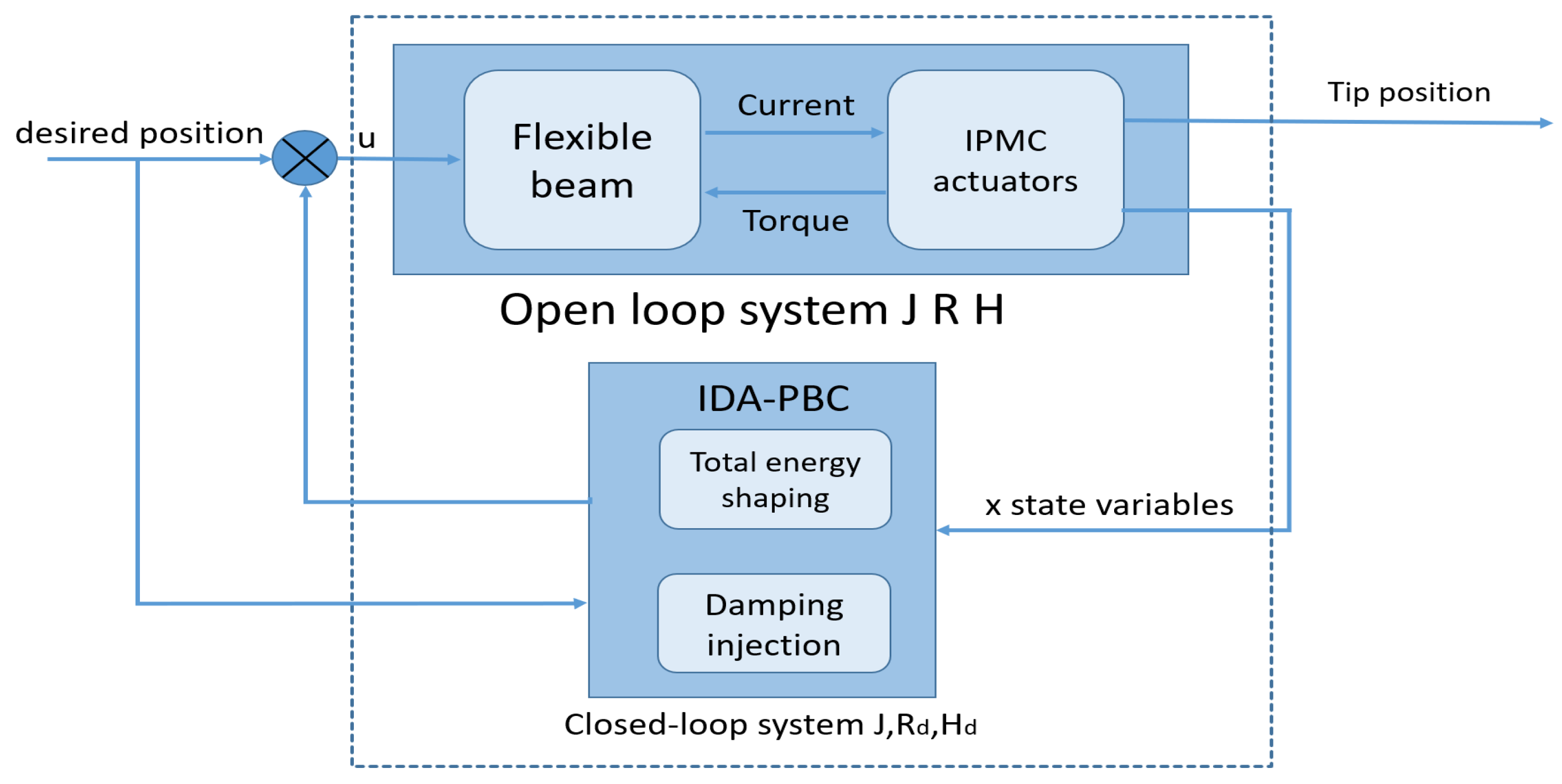
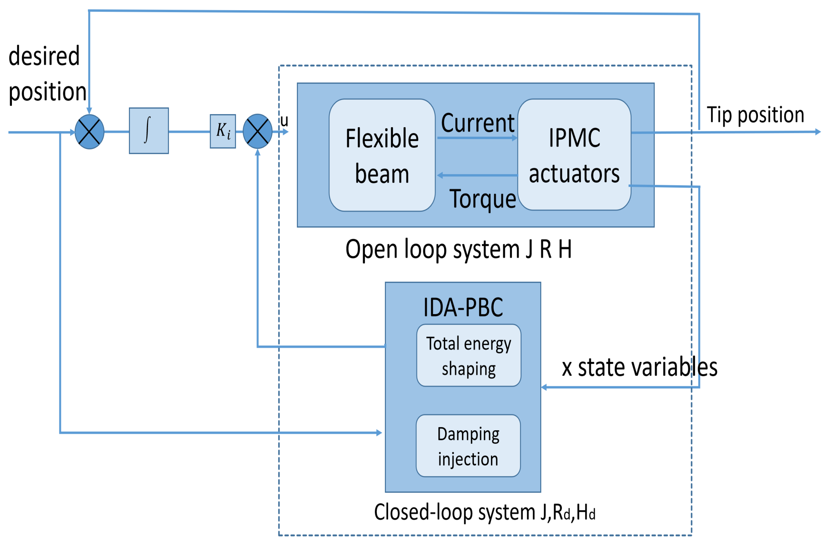
In this section, we propose a control law of the overall endoscope system (12). The control objective is to achieve a desired position of the beam and to acquire a desired performance by regulating the input voltages of the IMPC patches. The control block diagram is depicted in Figure 3, where the coupled system to control is composed of a flexible beam and several IPMC actuator patches interconnected by current and torque. The control law is designed for interconnection and damping assignment passivity-based control (IDA-PBC [14,26]). The main idea of the control law is to match the open-loop system with a target system using state feedback control law.
3.1. Ida-Pbc Control Method
First, we briefly recall the basic principles of the IDA-PBC methodology developed in [14]. We consider a open-loop port-Hamiltonian system in its general form, and we stabilize it around a desired equilibrium point .
Let us define an asymptotically stable PHS target system
with matrices and , and the desired Hamiltonian function verifies the PDE:
is a full rank left annihilator of g, i.e., . The PDE is a so-called matching condition. Furthermore, the Hamiltonian function should satisfy the following:
The closed-loop port-controlled Hamiltonian system with the feedback law
is (locally) and asymptotically stable at the equilibrium ; see [14] for details.
Hereafter, with the Port-Hamiltonian formulation of the representation of the interconnected total system, we propose the control laws for the stabilization of an IPMC-actuated flexible beam.
3.2. Control Design
In this subsection, we propose an IDA-PBC control law to stabilize the complete system (12). The control design is applied on the discretized port-Hamiltonian system (15), which allows us to preserve the structure. We match the open-loop system with a target system using state feedback control law, as described in Figure 3.
First, we consider not modifying the closed-loop interconnection matrix . As the system has a sensitive oscillator due to the mechanical nature of the beam, we consider additional energy damping .
In order to find the set of desired Hamiltonian functions as proposed in [14], Equation (15) is projected onto the orthogonal space corresponding to the matching condition with input matrix :
where is a full rank annihilator. To facilitate the calculation, we set as follows:
We define the desired closed-loop Hamiltonian in the quadratic form:
The equilibrium profile vector is defined as follows:
We set the symmetric matrix as follows:
with the desired equilibrium position of the system as .
Remark 2.
, , and are the desired stiffness vector, desired capacitance vector, and desired inductance vector of the closed-system to be calculated. are constant vectors. We show later that these vectors are control parameters, and the parametrization of is used for the resolution of matching equations so that the matching conditions are satisfied.
We set using the discretized system (15), and we find the developed form from the matching condition (21):
where , , and .
We find that the desired Hamiltonian function is independent from , , and and has cross terms among , , and Q from the matching Equations (26)–(28). Thus, we set the gradients of the desired Hamiltonian as follows:
Taking Equations (29)–(31); the set gradients of the closed-loop Hamiltonian; and the gradients of open-loop Hamiltonians , , and into account, we have the gradients of :
where , , and
Remark 3.
From the complete system dynamic (12), by computing , we find the equilibrium relation among , , and :
The condition (19) guarantees that, in the closed-loop Hamiltonian system, the equilibrium is the strict minimum, and the following equation interprets this condition:
The left side of Equation (38) is verified naturally by setting the gradient in Equation (29) to that in Equation (31). The inequality on the right side of Equation (38) indicates that the Hessian of should be positive definite at the desired equilibrium, which yields the following condition on the control design parameter :
4. Control Validation by Experimentation and Simulation
In this section, through experimentation and simulations, we present the performances of the closed-loop system with the designed nonlinear state feedback controls for the one-IPMC patch case and for the multi-actuation case of the flexible beam. The control objective here is to stabilize the coupled system (12) with one or several IPMC actuators to a specific steady state using the finite dimensional IPA-PBC controller (39). The desired position profile is computed by the transverse momentum distribution .
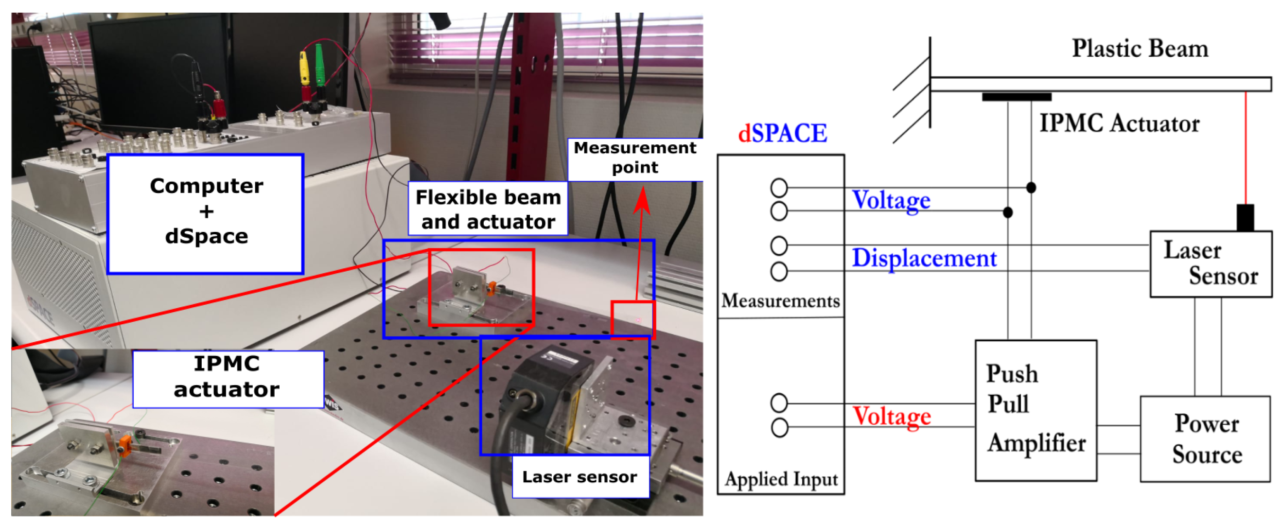
Figure 4 presents the experimental setup. We use a dSPACE control interface and a PC with MATLAB and the Simulink software to acquire the measurements and to implement the controller by generating the voltage across the IPMC patch. The measurement of displacement is acquired by the KEYENCE (LK-G152) laser displacement sensor.
The physical parameters and the identified parameters are shown in Table 1. All these parameters are obtained by identification from the experiment setup of Femto Lab, Besancon, France.
4.1. Control of a Single IPMC-Actuated Flexible Beam
This subsection illustrates the closed-loop behavior of the system obtained through experimentation with the IDA-PBC control law (39) from Section 3 for a flexible beam actuated by a single IPMC actuator using the voltage across the IPMC as the control input. The control objective is to drive the system to this desired profile and to reduce the beam vibration. In this case, the length of the IPMC patch is 0.045 m, and the IPMC patch is placed in the middle of the flexible beam between 0.0575 m and 0.01025 m along a total length of 0.16 m. In the following, the tip displacements are measured experimentally by the laser sensor.
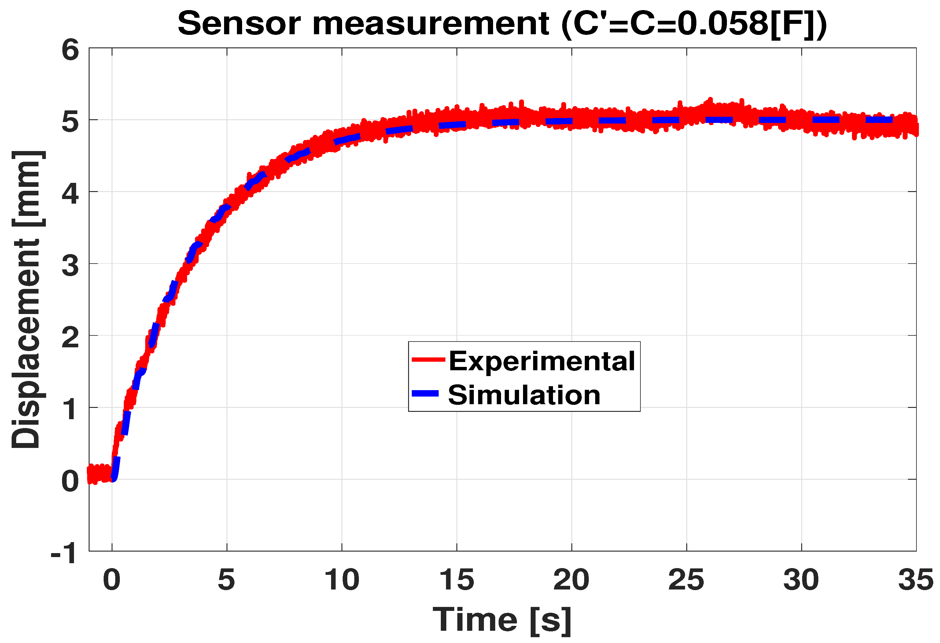
In Figure 5, we present the experimental results using the IDA-PBC control law without changing the control parameter , i.e., , and only the desired beam tip position is set at 5 mm.
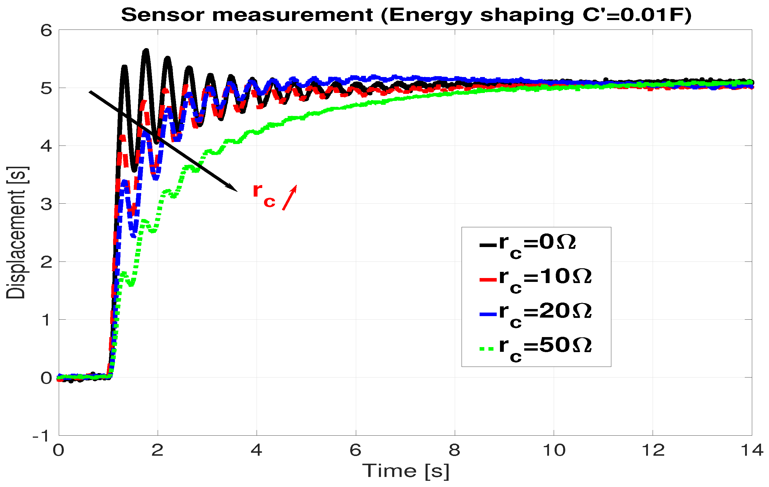
In order to improve the time response, we shape the closed-loop energy by varying the control parameter . In Figure 6, we present the experimental results using the IDA PBC control law with energy shaping. The control design parameter to assign the closed-loop dynamic is chosen as F, and the desired beam tip position stays the same. The raising time is drastically reduced compared with the closed-looped system without changing C in Figure 5.
The endpoint of the IPMC-actuated structure is presented in Figure 6. One can observe that, without a damping injection, the response oscillates a lot due to the beam flexibility (the solid black line). To cope with this oscillation, the damping injection is introduced into the control law. The oscillation is reduced significantly while the added damper increases.
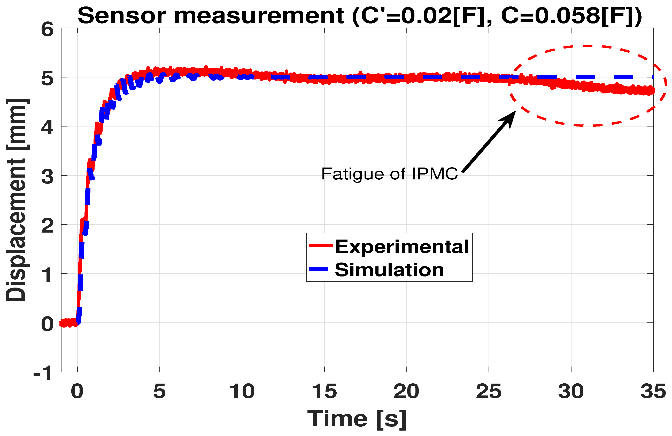
It is well known that the activity of IPMC actuators depends on their humidity (the concentration of the water molecule), which decreases during their actuation. It is validated by experiment in [27] that as the humidity level goes down, the Young’s modulus continuously increases, the strain-rate damping coefficient and dielectric constant continuously decrease, which lead to the activity reduction of IPMC. This phenomenon has been observed during the experimental validation of the proposed IDA-PBC controller shown in Figure 7. We can see that, at the end of the actuation, the activity of the IPMC actuator is visibly reduced. To overcome this default, we propose adding an integral action on the controller (39). The integral of the error between the desired tip position and the real tip position q is added as follows:
where u is the IDA-PBC control law obtained in Equation (39). In this case, the control diagram becomes the following (Figure 8):
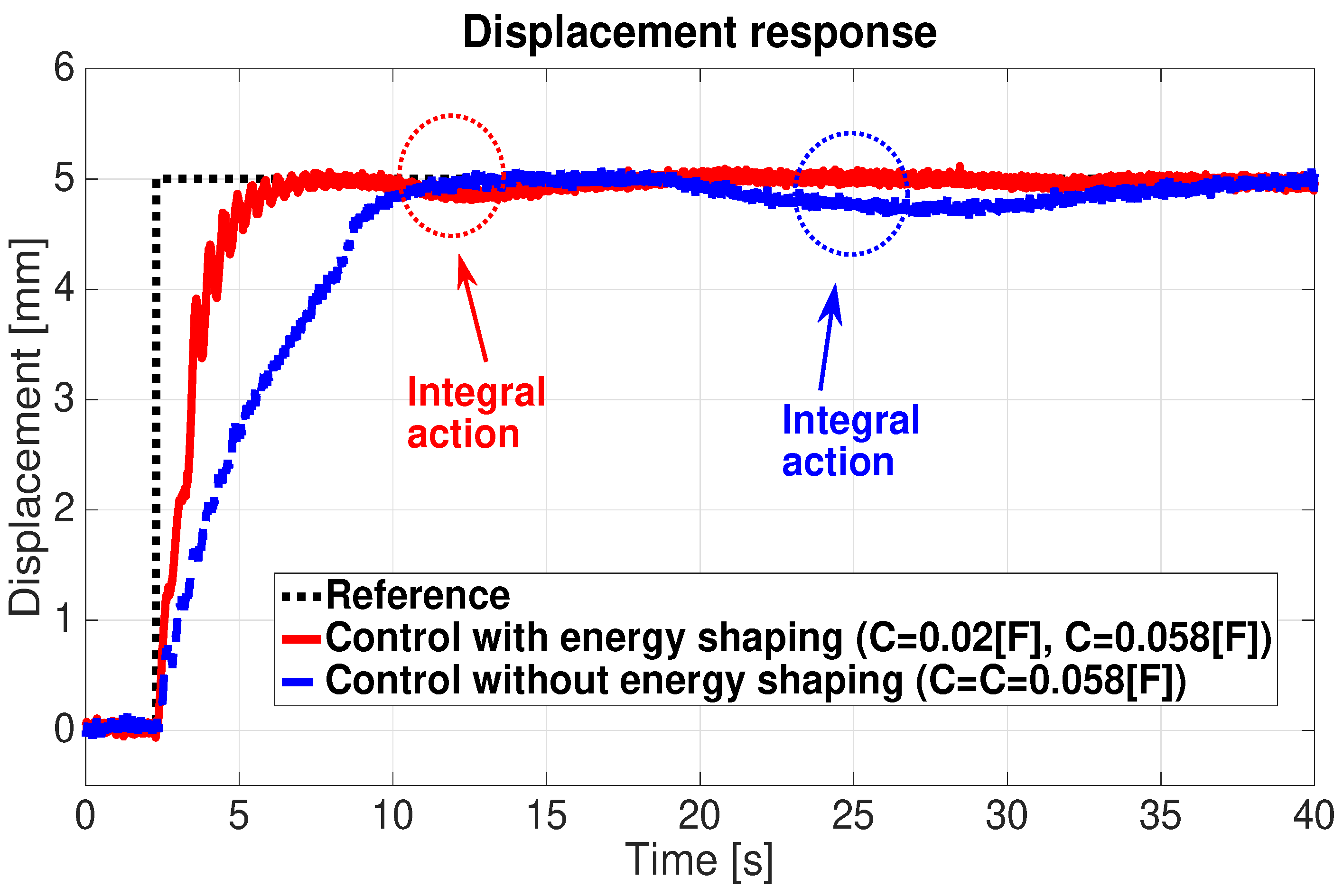
The above proposed controller (40) is also implemented in the experimental setup. In Figure 9, the integral action is added to two IDA-PBC different controllers. The blue dashed line presents a closed-loop response with the IDA PBC controller parameter F. The integral action is activated at 25 s when the IPMC starts to lose its activity and the beam tip position starts to decline. One can see that the beam tip returns to the desired position. The red solid line shows the closed-loop response with IDA-PBC controller parameter . The integral action can overcome the default when the IPMC actuator becomes less efficient due to the decrease in the water molecule concentration of the actuator.
4.2. Multi-Actuation of a Flexible Beam
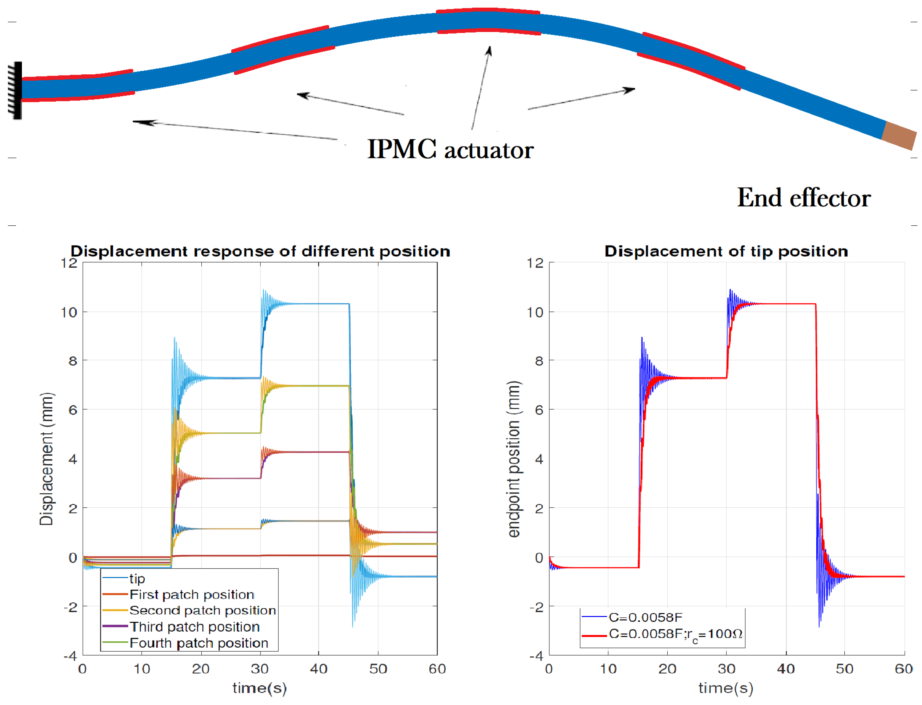
In order to improve the spatial accessibility to satisfy the endoscope working condition, the flexible beam should be capable of being shaped into a desired shape. We proposed a multi-actuated flexible structure. The flexible beam is actuated by four IPMC patches. The IPMC patches are placed along the clamped side at 0–0.018 m, and the others are placed between and m, between and m, and between and 0.126 m, as shown in the top half of Figure 10. The control objective is to converge the system to the desired configuration of the endoscope (Figure 10), defined by the joint and tip position mm, and to reduce the beam vibration simultaneously.
We recall the distributed input map of the flexible beam model:
where represent the ith patch of the IPMC actuators glued onto the beam. The distributed input variables are the distributed moment: on the ith small intervals of the spatial space . if , which means an IPMC actuator is in the interval , and elsewhere.
We choose the design parameter . Different IPMC patches were actuated sequentially from the clamped side to the free-hand side. Different IPMC patches are actuated at , and 45 s. The bottom left side of Figure 10 illustrates the different positional displacements of the beam for the control law with () or without damping injection. The bottom right side of Figure 10 illustrates the tip displacement for the control law with and without damping injection. We can conclude that, with the proposed control law, we can shape the beam to the desired shape.
5. Conclusion and Perspectives
We investigate the modeling and the control design problem of a IPMC-actuated flexible beam using the port-Hamiltonian approach. The flexible beam dynamic is modelled by a Timoshenko beam model, while the IPMC actuator dynamic is described by a lumped RLC equivalent circuit model. It has been shown that the PDE-described flexible beams are interconnected with the ODE-described IPMC actuator model. The control strategy is composed of an IDA-PBC passive control method coupled with damping injection. The closed-loop response time of the system is accelerated by energy shaping, while the damping injection is used to compensate for the oscillation of the flexible beam. Finally, an experimental setup was applied to validate the proposed control law. In the mono-actuation case, the control law implemented stabilizes the system to the desired position. The closed-loop response was visibly faster, and the vibration of beam was reduced significantly with the damping injection. However, at the end of actuation, the activity of the IPMC actuator was visibly reduced due to its physical nature, which causes the lack of humidity to reduce the activity of the material. An integral action was added to the controller in order to overcome this limitation. Furthermore, a multi-actuation case with four IPMC patches was simulated in order to shape the beam to a desired shape. The simulation result shows the effectiveness of the control method presented.
As a prospective work, we shall consider the parameter uncertainty and the effect of external perturbations as the actuation of IPMC is sensitive to humid working conditions. We shall complete the study with an analysis and demonstration of the integral action for the designed controls. The robustness of the control law will also be investigated in future work. Furthermore, the complete IPMC actuator model under a port-Hamiltonian framework was proposed in [11], where the diffusion of water and the cations of the polymer were considered. How this complete actuator model can be used to control the flexible beam will be considered.
Author Contributions
W.Z. participated in the study conception, manuscript writing and revision and secured the researching funding. Y.W. (Yongxin Wu) participated in the study conception, manuscript writing and revision and discussion. H.H. involved in data analyses, participated in formal analysis and discussion of critical points. Y.L. conceptualized the study design, secured the researching funding. Y.W. (Yu Wang) participated in the data analysis and the original paper preparation. All authors have read and agreed to the published version of the manuscript.
Funding
This research is supported by by the National Natural Science Foundation of China (No. 62073290) and Zhejiang Province Natural Science Fund (LY20F030003) and Zhejiang Provincial Natural Science Foundation of China under grant no. LQ21F030008 and project Intelligentization and Digitization for Airline Revolution 2018R02008 and Agence Nationale de la Recherche: ANR-17-EURE-0002 and Bourgogne Franche Comté region of France (ANER 2018Y-06145).
Conflicts of Interest
The authors declare no conflict of interest.
References
- Chikhaoui, M.T.; Rabenorosoa, K.; Andreff, N. Kinematic modeling of an EAP actuated continuum robot for active micro-endoscopy. In Advances in Robot Kinematics; Springer International Publishing: Berlin/Heidelberg, Germany, 2014; pp. 457–465. [Google Scholar]
- Shahinpoor, M.; Kim, K.J. Ionic polymer-metal composites: I. Fundamentals. Smart Mater. Struct. 2001, 10, 819. [Google Scholar] [CrossRef]
- Maschke, B.; van der Schaft, A. Port Controlled Hamiltonian Systems: Modeling Origins and System Theoretic Properties; IFAC Nonlinear Control Systems Design: Bordeaux, France, 1992. [Google Scholar]
- Mattioni, A.; Wu, Y.; Le Gorrec, Y. Infinite dimensional model of a double flexible-link manipulator: The Port-Hamiltonian approach. Appl. Math. Model. 2020, 83, 59–75. [Google Scholar] [CrossRef]
- Monshizadeh, P.; Machado, J.E.; Ortega, R.; van der Schaft, A. Power-controlled Hamiltonian systems: Application to electrical systems with constant power loads. Automatica 2019, 109, 108527. [Google Scholar] [CrossRef] [Green Version]
- Hoang, H.; Couenne, F.; Jallut, C.; Le Gorrec, Y. The port Hamiltonian approach to modeling and control of Continuous Stirred Tank Reactors. J. Process. Control 2011, 21, 1449–1458. [Google Scholar] [CrossRef] [Green Version]
- Maschke, B.; van der Schaft, A. Hamiltonian representation of distributed parameter systems with boundary energy flow. In Nonlinear Control in the Year 2000; Springer: London, UK, 2000; pp. 137–142. [Google Scholar]
- Le Gorrec, Y.; Zwart, H.; Maschke, B. Dirac structures and boundary control systems associated with skew-symmetric differential operators. SIAM J. Control Optim. 2005, 44, 1864–1892. [Google Scholar] [CrossRef] [Green Version]
- Zhou, W.; Hamroun, B.; Couenne, F.; Le Gorrec, Y. Distributed port-Hamiltonian modelling for irreversible processes. Math. Comput. Model. Dyn. Syst. 2017, 23, 3–22. [Google Scholar] [CrossRef]
- Nishida, G.; Takagi, K.; Maschke, B.; Osada, T. Multi-scale distributed parameter modeling of ionic polymer-metal composite soft actuator. Control. Eng. Pract. 2011, 19, 321–334. [Google Scholar] [CrossRef]
- Liu, N.; Wu, Y.; Le Gorrec, Y. Energy based modeling of ionic polymer metal composite actuators dedicated to the control of flexible structures. IEEE/ASME Trans. Mechatronics 2021. [Google Scholar] [CrossRef]
- Macchelli, A. Energy shaping of distributed parameter port-Hamiltonian systems based on finite element approximation. Syst. Control Lett. 2011, 60, 579–589. [Google Scholar] [CrossRef]
- Ramírez, H.; Le Gorrec, Y.; Macchelli, A.; Zwart, H. Exponential stabilization of boundary controlled port-Hamiltonian systems with dynamic feedback. IEEE Trans. Autom. Control 2014, 59, 2849–2855. [Google Scholar] [CrossRef] [Green Version]
- Ortega, R.; van der Schaft, A.; Maschke, B.; Escobar, G. Interconnection and damping assignment passivity-based control of port-controlled Hamiltonian systems. Automatica 2002, 38, 585–596. [Google Scholar] [CrossRef] [Green Version]
- Ortega, R.; van der Schaft, A.J.; Mareels, I.; Maschke, B. Putting energy back in control. IEEE Control Syst. Mag. 2001, 21, 18–33. [Google Scholar]
- Mattioni, A.; Wu, Y.; Ramirez, H.; Le Gorrec, Y.; Macchelli, A. Modelling and control of an IPMC actuated flexible structure: A lumped port Hamiltonian approach. Control Eng. Pract. 2020, 101, 104498. [Google Scholar] [CrossRef]
- Wu, Y.; Lamoline, F.; Winkin, J.; Le Gorrec, Y. Modeling and control of an IPMC actuated flexible beam under the port-Hamiltonian framework. IFAC-PapersOnline 2019, 52, 108–113. [Google Scholar] [CrossRef]
- Jacob, B.; Zwart, H.J. Linear Port-Hamiltonian Systems on Infinite-Dimensional Spaces; Springer Science & Business Media: Berlin/Heidelberg, Germany, 2012; Volume 223. [Google Scholar]
- Macchelli, A.; Melchiorri, C. Modeling and control of the Timoshenko beam. The distributed port Hamiltonian approach. SIAM J. Control Optim. 2004, 43, 743–767. [Google Scholar] [CrossRef] [Green Version]
- Gutta, S.; Lee, J.S.; Trabia, M.B.; Yim, W. Modeling of ionic polymer metal composite actuator dynamics using a large deflection beam model. Smart Mater. Struct. 2009, 18, 115023. [Google Scholar] [CrossRef]
- Golo, G.; Talasila, V.; van der Schaft, A.; Maschke, B. Hamiltonian discretization of boundary control systems. Automatica 2004, 40, 757–771. [Google Scholar] [CrossRef] [Green Version]
- Moulla, R.; Lefèvre, L.; Maschke, B. Pseudo-Spectral Methods for the Spatial Symplectic Reduction of Open Systems of Conservation Laws. J. Comput. Phys. 2011, 231, 1272–1292. [Google Scholar] [CrossRef] [Green Version]
- Trenchant, V.; Ramirez, H.; Le Gorrec, Y.; Kotyczka, P. Finite differences on staggered grids preserving the port-Hamiltonian structure with application to an acoustic duct. J. Comput. Phys. 2018, 373, 673–697. [Google Scholar] [CrossRef]
- Kotyczka, P. Finite Volume Structure-Preserving Discretization of 1D Distributed-Parameter Port-Hamiltonian Systems. IFAC-PapersOnLine 2016, 49, 298–303. [Google Scholar] [CrossRef] [Green Version]
- Rashad, R.; Califano, F.; van der Schaft, A.J.; Stramigioli, S. Twenty years of distributed port-Hamiltonian systems: A literature review. IMA J. Math. Control Inf. 2020, 37, 1400–1422. [Google Scholar] [CrossRef]
- Ortega, R.; Garcia-Canseco, E. Interconnection and damping assignment passivity-based control: A survey. Eur. J. Control 2004, 10, 432–450. [Google Scholar] [CrossRef]
- Lei, H.; Lim, C.; Tan, X. Humidity-dependence of IPMC sensing dynamics: Characterization and modeling from a physical perspective. Meccanica 2015, 50, 2663–2673. [Google Scholar] [CrossRef]
Figure 1.
IPMC-actuated compliant endoscope.

Figure 2.
Physical structure of the IPMC actuator and its electrical model.

Figure 3.
Control diagram.

Figure 4.
Experimental setup.

Figure 5.
IDA-PBC closed-loop response without changing the control parameter C.

Figure 6.
Closed loop response with IDA-PBC and damping injection.

Figure 7.
Closed loop response with the fatigue of the IPMC actuator.

Figure 8.
Control diagram with integral action.

Figure 9.
Closed-loop response with the IDA PBC control and the integral action.

Figure 10.
Desired configuration of the endoscope (control objective).


Table 1.
Numerical values of the parameters.
| L | Length | m |
|---|---|---|
| W | Width | m |
| T | Thickness | m |
| Mass density | 936 kgm | |
| I | Inertia moment of area | m |
| Angular moment of inertia | kg | |
| E | Young’s modulus | Pa |
| K | shear modulus | Pa |
| Traversal viscous fraction | kgm/s | |
| Angular viscous fraction | kgm/s | |
| C | Capacitance | F |
| Resistance | 29.75 | |
| Resistance | 700 |
Publisher’s Note: MDPI stays neutral with regard to jurisdictional claims in published maps and institutional affiliations. |
© 2021 by the authors. Licensee MDPI, Basel, Switzerland. This article is an open access article distributed under the terms and conditions of the Creative Commons Attribution (CC BY) license (https://creativecommons.org/licenses/by/4.0/).
Share and Cite
MDPI and ACS Style
Zhou, W.; Wu, Y.; Hu, H.; Li, Y.; Wang, Y. Port-Hamiltonian Modeling and IDA-PBC Control of an IPMC-Actuated Flexible Beam. Actuators 2021, 10, 236. https://0-doi-org.brum.beds.ac.uk/10.3390/act10090236
AMA Style
Zhou W, Wu Y, Hu H, Li Y, Wang Y. Port-Hamiltonian Modeling and IDA-PBC Control of an IPMC-Actuated Flexible Beam. Actuators. 2021; 10(9):236. https://0-doi-org.brum.beds.ac.uk/10.3390/act10090236
Chicago/Turabian StyleZhou, Weijun, Yongxin Wu, Haiqiang Hu, Yanjun Li, and Yu Wang. 2021. "Port-Hamiltonian Modeling and IDA-PBC Control of an IPMC-Actuated Flexible Beam" Actuators 10, no. 9: 236. https://0-doi-org.brum.beds.ac.uk/10.3390/act10090236
Note that from the first issue of 2016, this journal uses article numbers instead of page numbers. See further details here.