
Design and Test of an Active Pneumatic Soft Wrist for Soft Grippers


1
Laboratory of Locomotion Bioinspiration and Intelligent Robots, College of Mechanical and Electrical Engineering, Nanjing University of Aeronautics and Astronautics, 29 Yudao Street, Nanjing 210016, China
2
College of Civil Aviation, Nanjing University of Aeronautics and Astronautics, No. 29 Jiangjun Avenue, Nanjing 210016, China
3
School of Mechanical Engineering, Xi’an Jiaotong University, No. 28 Xianning West Road, Xi’an 710049, China
4
School of Engineering, College of Engineering, Science & Environment, Callaghan Campus, University of Newcastle, University Drive, Callaghan, NSW 2308, Australia
*
Author to whom correspondence should be addressed.
Actuators 2022, 11(11), 311; https://0-doi-org.brum.beds.ac.uk/10.3390/act11110311
Submission received: 7 October 2022
/
Revised: 24 October 2022
/
Accepted: 24 October 2022
/
Published: 27 October 2022
(This article belongs to the Special Issue Soft Actuators and Robotics)
Abstract
:An active wrist can deliver both bending and twisting motions that are essential for soft grippers to perform dexterous manipulations capable of producing a wide range movements. Currently, the versions of gripper wrists are relatively heavy due to the bending and twisting motions performed by the motors. Pneumatic soft actuators can generate multiple motions with lightweight drives. This research evaluates a pneumatic soft wrist based on four parallel soft helical actuators. The kinematics models for predicting bending and twisting motions of this soft wrist are developed. Finite element method simulations are conducted to verify the functions of bending and twisting of this wrist. In addition, the active motions of the soft pneumatic wrist are experimentally demonstrated. Based on sensitivity studies of geometric parameters, a set of parameter values are identified for obtaining maximum bending and twisting angles for a bionic human wrist. Through simulation and experimental tests of the soft wrist for a soft gripper, the desired bending and twisting motions as those of a real human hand wrist are established.
1. Introduction
Soft robotic grippers can be used to grasp various objects and have been applied in many industrial practices [1,2,3,4,5,6]. To increase the dexterity of grippers, an active soft wrist is highly desired due to its ability to increase grasping ranges and perspectives [7,8]. Contemporarily, these movements of bending and twisting for the wrists of grippers are achieved by the forces and torques generated by a series of motors [9,10]. Although different motions are obtained, the multiple motors used in the wrist make it relatively heavy and they cause a high energy consumption. In addition, it is difficult to achieve specific bending or twisting angles via the adjustment of forces and torques by the motors [11].
Compared to the wrists of soft grippers whose motions are driven by motors, pneumatic soft actuators are convenient to generate bending motions [12,13,14,15] or twisting motions [16,17,18,19] using a lightweight driving system that is mostly composed of air pumps, tubes and control components. Thus, pneumatic soft actuators have been investigated for achieving multiple motions with lightweight drives [20,21]. For instances, Kurumaya et al. [22] designed a soft wrist using two types of fiber-reinforced soft actuators whose structural design is similar to the mechanism of a human wrist. The wrist consists of a bending module and a rotary module of fiber-reinforced elastic cylinders that can perform bending and rotation motions in correspondence to different segments. Fei et al. [23] developed a biaxial bidirectional cylinder-shaped soft actuator. The wrist can perform flexion/extension, ulnar/radii deviation, and bending in other directions by pressurizing different chambers. This wrist can increase the range orientations for grasping an object, making the soft gripper versatile to grip objects via various poses. Shen et al. [24] designed a soft wrist that consists of three fluidic actuators, a ball joint, and two 3D printed plates. The three soft actuators are placed triangularly and the top and bottom plates are connected by a ball joint. When one actuator is elongated, the other two will be contracted accordingly, which will result in the bending motion along with contracted actuators. The dexterity of the hand has been improved due to the advantage of increased motions.
Therefore, the available soft wrists can perform either bending or twisting motions at varied segments. They are not yet able to achieve both bending and twisting movements in one segment [25], which thus could not resemble twisting behaviors of a human wrist when grasping from various perspectives. To enhance grasping ranges and perspectives for robotic grippers, it is essential to develop a pneumatic active soft wrists that can present bending and twisting motions in one segment.
Fiber-reinforced pneumatic soft actuators have the advantage of performing multiple motions by a varying chamber structure, orientation of winding fibers and pressure [21,26]. The winding fibers on soft actuators also reinforce their strength with respect to high air pressure [17]. For pneumatic soft helical actuators, the characteristics of the helical structures of the soft actuators are decisive to their twisting motions [18,19]. In addition, antagonistic actions can be utilized to increase the overall stiffness of the whole structure [27]. Accordingly, with innovative structure design by using different helical actuators, the motions of bending and twisting and sufficient stiffness for an active soft wrist can be achieved for a single segment.
This paper contributes to the research field by presenting an active soft wrist that can achieve bending and twisting motions for one segment. This segment consists of four parallel soft helical actuators. This driving system is lightweight and energy-saving because only one air pump is used. A kinetic analysis, finite element simulations, and experimental tests were carried out to evaluate the wrist’s bending and twisting angles for different air pressures. Moreover, the influences of geometric parameters on bending and twisting angles are predicted by using finite element method simulations. Using a set of optimized geometric parameters, a soft wrist was manufactured and the dexterity is demonstrated based on the performances on a soft pneumatic hand.
2. Structure Design
This section illustrates the structural design of the pneumatic active soft wrist. First, the structure and motions of two pneumatic actuators of opposite helical structures are introduced. On this basis, the soft wrist design composed of four helical actuators is provided, and the mechanisms for producing bending and twisting motions are explained.
2.1. Structure of Pneumatic Helical Actuators
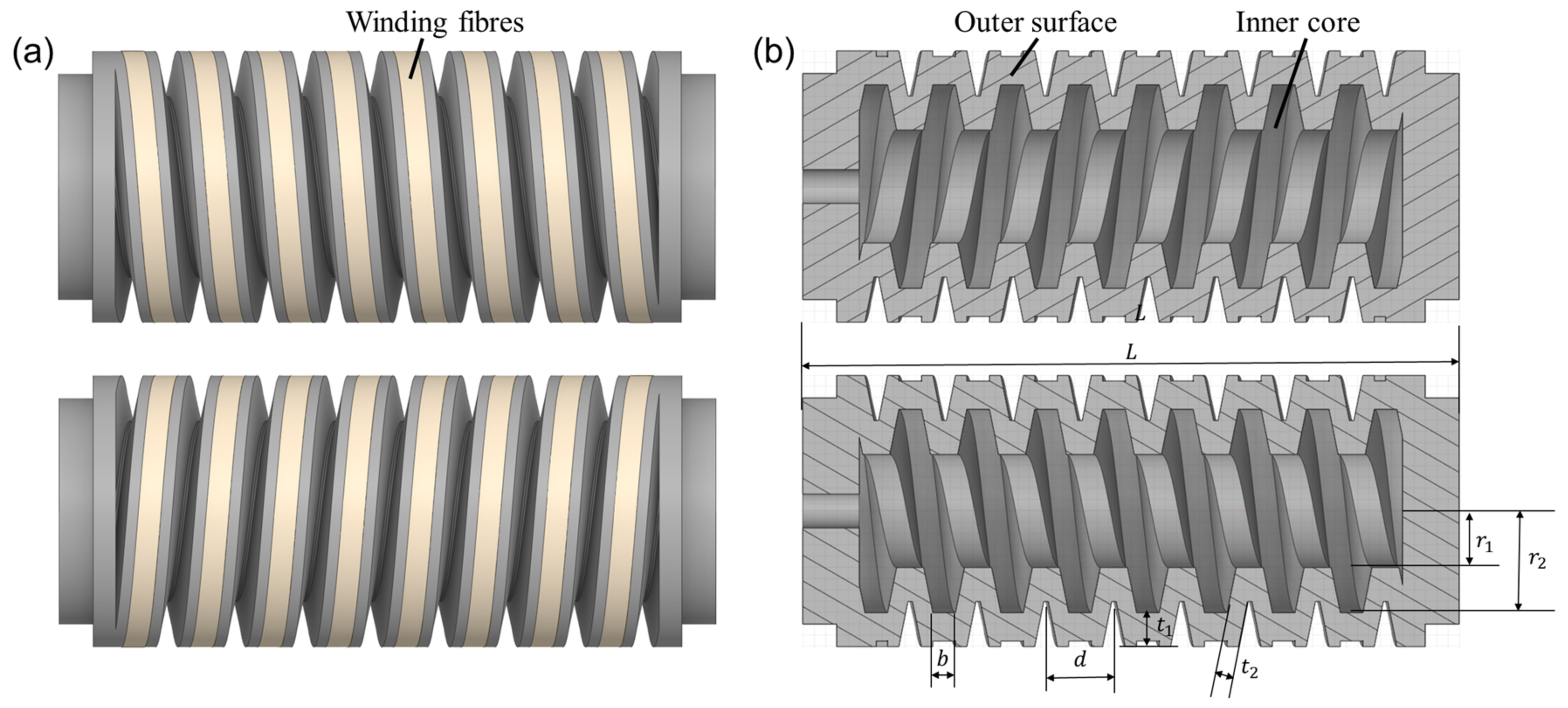
Figure 1a presents two pneumatic soft helical actuators of the same geometric sizes but opposite helical directions. Each actuator possesses a soft chamber whose outer surface is winded by the fiber of a rectangular strip. The chamber has a universal outer and inner helical structure. Under pressurization, the winding rectangular fiber restrains the radial expansion, such that the soft actuators elongate and twist in accordance with the helical directions [26]. Due to the different orientations of the winding fiber, the actuators twist in different directions [17]. As denoted in Figure 1b, the chamber structural parameters include the overall length L, the inner hole radius , the inner helix radius , the inner helix width b, the helix pitch d, the outward layer thickness and the inward layer thickness . Note that the width of the fiber is equal to the inner helix width b for sufficient restraining inflation of the chamber.
2.2. Structure Design of the Pneumatic Soft Wrist
Section 2.1 explained the elongation and twisting characteristics of a single pneumatic helical soft actuator. By bonding two soft actuators of opposite helical directions that are under pressurization (i.e., A&B of Figure 2a), the twisting effects of the two actuators are offset. When adding another two such actuators (i.e., C&D of Figure 2a), the longitudinal extension of the pressured actuators (A&B) can be restrained. In that case, the whole structure will produce a forward bending motion. Figure 2b illustrates a cross-sectional view and the helical directions of the soft wrist. With this structure, twisting of the whole structure can also be achieved by pressurization of diagonal actuators (i.e., A&C or B&D). When all of the four helical chambers are pressurized, the twisting torques of the four actuators are offset due to antagonistic actions, and the stiffness of the wrist can be improved [27].
Table 1 illustrates four bending motions and two twisting motions caused by the pressurizations of different chambers. The green color of the chamber cores represent the actuators that are inflated and the green arrow denotes the motion direction of the soft wrist. For the bending motion shown in the first row of Table 1, the chambers A and B are pressurized, and the bending occurs along the negative Y direction. Likewise, the bending motions backward, left, and right can be achieved in accordance with the pressurization of neighboring chambers. The left or right twisting motions around the Z axis can be achieved similarly with the pressurization of the diagonal chambers. To increase the stiffness of the soft wrist while maintaining their motions, the same amount of air pressure can be simultaneously applied to all four chambers.
Summarizing, this subsection presented the design of a soft joint based on four pneumatic soft helical actuators. The six motions of direction of the soft joint can be obtained by the pressurization of specific chambers. To assess the bending and twisting motions of the soft wrist, a kinematic analysis will be presented in the next section.
3. Kinematic Analysis
The bending and twisting angles can be used to assess the performances of the soft wrist under different applied air pressures [15,19]. To establish the relationships between the input pressure and the angles of bending and twisting of the soft wrist, this section presents approaches for theoretical predictions based on the kinematics analysis of a single actuator.
3.1. Bending Model
Figure 3a presents the bending model of the soft wrist subjected to two upper pressured adjacent actuators. The left side of the wrist is fixed and the bending motion of the soft wrist is triggered when the two upper actuators equally compress the two lower actuators. To deduce the bending equation for the soft wrist, the kinematic of bending for a single pressured actuator is studied. Figure 3b shows the bending forces and torques of the soft actuator of the longitudinal section. The transverse circular section of the actuator chamber bottom is shown in Figure 3c. Based on the principle that the bending moment caused by the input air pressure equates to that generated by material deformations during pressurization [28], the bending angle in respect to the applied pressure can be derived as is given below.
The actuator length is denoted by L, the bending angle by θ, and the curvature radius by ; is the external moment imposed by the air pressure about bottom edge O; is the material moment generated by the actuators’ inner wall resistance. The force df, generated by air pressure on a micro-area of height dh, is:
Using the geometric characteristic , the bending moment of the single actuator with respect to the bottom edge O can be expressed as:
where is the average equivalent thickness of the actuator chamber, which can be estimated by:
For the helical soft chamber, the axial principle stress is the main internal stress responsible for the bending of the actuator [29]. For the circular section of the chamber, the axial principal stretch ratio is given by:
Then, the chamber material intrinsic resistance moment can be calculated as:
Solving the equation of moment equilibrium , the relationship between the input pressure of the actuator and its bending angle can be obtained.
3.2. Twisting Model
Figure 4a presents the twisting model of the soft wrist where two diagonal actuators are pressured whilst the bottom of the wrist is fixed. The two pressured actuators synchronously twist and cause the wrist to twist. The kinematics for a single twisting actuator are investigated to derive the twisting angle of the soft wrist. The twisting motion of the actuator is generated by the torques approximately with respect to its central axis [19]. The longitudinal section of a twisting actuator is shown in Figure 4b. The torques of the pressured actuator are given in Figure 4c. The equation of the moment balance equilibrium for the torque generated by air pressure and the torque generated by the material is used to derive the twist angle with respect to applied pressure.
The twisting of the actuator is mainly caused by the pressure applied on the inner helical structure surface of the chamber [18]. The parametric equation for the helix curvature of the inner helical structure can be expressed as:
where is the helix angle; . Neglecting the mutual resistance of the actuators, the torque generated by the pressure on inner helical structure surface with respect to the fixed end can be expressed as:
where is the width of the fiber cloth and H is the curve equation of the helix. The axial principal stress is the main internal stress for the bending of the actuator. For circular sections, the axial principal stretch ratio is given by [30]:
The tangential stress τ for twisting angle of a single actuator can be expressed by:
in which:
where and are the material coefficients of the soft chamber and winding fiber, respectively [30]; is the fiber cloth winding angle. Then, the torsional moment generated by the material can be calculated as:
Using , the correlations between the torsional angle and the chamber pressure can be solved for the single actuator. The twisting angle for the wrist can be considered equal to by neglecting the mutual resistance between the four chambers.
Summarizing, this section illustrated the approaches for estimating the relationships between input pressure and the bending and twisting angles. When the material and structure parameters of the soft wrist are determined, the bending and twisting angles can be calculated to assess the performance of the soft wrist under different applied air pressures.
4. Numerical Modeling
The previous section illustrated theoretical approaches for deriving bending and twisting angles of the soft wrist. To assess the accuracy of the theoretical analysis, finite element method simulations were carried out to predict the bending and twisting motions of a soft wrist whose size is comparable to a human wrist.
4.1. Simulation Parameters
The helical actuators are made of a soft silicone chamber and Kevlar fiber. The silicone rubbers are modeled as nonlinear elastic, isotropic, and incompressible under quasi-static loading. Finite element analyses (FEAs) are often conducted for modeling mechanical responses of the soft wrist. The simulations of the bending and twisting motion can be studied by modeling the soft wrist in the static structure module of ANSYS Workbench (2021R1) [31,32]. Using the hyperelastic incompressible Yeoh material model, the silicone chamber is modeled based on the theoretical Equation (12) [33,34]:
where is the strain energy; is a material constant (i = 1, 2, 3) and is the first invariant. For the experimental materials of Ecoflex 20 [34], the material parameter values are available in the literature [31]. The simulation parameters and their values for modelling materials are listed in Table 2. In the simulations, the quality of the silicone cavity is defined by the hyperelastic incompressible Yeoh material model. The silicone chamber is meshed using Solid187, which is a 10-node tetrahedral element that is adaptable to the model to generate high-quality meshes [31]. The fiber is modeled with cable elements. Bonded constraints are applied for the contacts of the chambers and the contacts between chamber and fiber. The fixed constraint is applied to the bottom of the soft wrist.
4.2. Simulation Results
For simulating the behaviors of a soft wrist under pressurization, a reference case was selected based on the sizes of a human wrist. It was assumed that a human wrist has a circular cross section, and its radius is approximately 50 mm. The radius of each actuator can then be determined at 12 mm. Based on this radius, the actuator length L was set to be 58 mm because on the one hand, a shorter length will not produce sufficiently large bending or twisting angles for a test pressure of 50 kPa, and on the other hand, longer actuators for the wrist are not necessary. The determination of the chamber thickness and diameter also affected the fabrication conditions of the soft actuators. The finally determined sizes were: cylinder core radius = 5 mm, inner helix radius = 8 mm, inner helix width b = 2 mm, helix pitch d = 7 mm, outward layer thickness , and inward layer thickness . In the simulation, a pressure of 50 kPa is applied to the chambers of the four actuators. When adjacent chambers (i.e., A&C, B&D) are pressurized, side bending motions can be achieved, as given in Figure 5a. When diagonal chambers (i.e., A&D, B&C) are pressurized, the twisting motions are shown in Figure 5b. The results are consistent with the analysis of soft wrist motions in Table 1.
5. Experimental Tests
The previous sections have theoretically and numerically evaluated the bending and twisting motions of the soft wrist. To validate the predicted motions, a real sample of the soft wrist used in the simulation model was fabricated. The experimental tests of bending and twisting motions were compared with the theoretical and simulation results.
5.1. Sample Fabrication
The soft chambers were fabricated with Ecoflex-0020 liquid silicone (Smooth-on Inc., Macungie, PA, USA) using a casting process [35]. The molds used for the actuators were fabricated by a 3D printer (Objet Connex 500, Stratasys corporation, Eden Prairie, MN, USA).) using resin material. Equal amounts of part A and part B of Ecoflex-0020 were mixed and stirred until the mixture was evenly dispersed. Then, the mixture was placed in a vacuum chamber at room temperature for 3 min to remove bubbles. Subsequently, the mixture was poured into the molds and put in a vacuum drying oven for 3 h at 70 °C for thorough molding. Four Kevlar fibers of 0.5 mm diameter were manually wound along the helix structure of the actuator outer surface. After the four actuators with wound fibers were molded, the soft silicon pipes of 3 mm diameter were added to the chamber ends. Then, the same liquid silicone was poured onto the contacts between the four actuators, and the contacts between the actuators and the pipes. Finally, the actuators were placed in a vacuum drying oven for one hour at 70 °C. In this way, a model of a soft wrist can be fabricated.
5.2. Experimental Results
Figure 6 shows the fabricated sample and the experimental setup, which was composed of a micro air pump (370-B), an air pump pressure knob board, and a pressure gauge (HT1895). The micro air pump was used to supply air to the soft actuators. The air pump pressure knob can regulate the air flow of the air pump. The pressure gauge was used to measure the output pressure from the air pump [36]. Figure 7 illustrates the bending and twisting motions of the soft wrist under pressure of 50 kPa. The experimental results of increasing pressure on bending and twisting angles are plotted in Figure 8, in which the results from simulations and theoretical tests were also shown. The calculations for the theoretical results between input pressure and angles of bending and twisting are elaborated below.
For the fabricated sample shown in Figure 7, using the Equations (2) and (5) and the parameter values in Table 2, the relationship between the bending angle θ of the soft wrist and the pressure can be estimated, which is given by below Equation (13). Likewise, using Equations (7) and (11), and the values in Table 2, the relationship between the twisting angle and the pressure can be obtained, which is expressed by Equation (14):
Figure 8 shows that overall, the bending and twisting angles of the soft wrist increased similarly with the increase of pressure for analytical, simulation, and experimental tests. The deviations between the three results are mainly ascribed to the simplified hyper-elastic model for the silicon chamber and the homogeneous assumptions for the restriction layers in the theoretical and simulation analysis [33]. To further illustrate that the deviations are small, the angles for bending and twisting for 50 kPa are denoted for the analytical, simulation, and experimental results. Both deviations of the bending and twisting angles are within 2.5%, which verifies that the simulation approach can be used to predict angles of bending and twisting for the soft wrist under pressure of 50 kPa.
6. Application for a Soft Hand
The previous section demonstrated that simulations are reliable for predicting angles of bending and twisting for the soft wrist under test pressures. In this section, the sensitivity of the geometric parameters on the bending and twisting of a soft wrist are studied using the simulation approach. Based on the optimal results, a series of values for the chamber structure were used to fabricate a soft wrist and implemented in the soft gripper.
6.1. Sensitivity Studies of Geometric Parameters
To obtain the maximal angles of bending and twisting while maintaining the length of the soft wrist, sensitivity studies of the chamber geometric parameters were conducted. To ensure that the chamber has sufficient space, the inner hole radius was not less than 4 mm. The inner helix radius was not greater than 10 mm referring to the size of a human wrist. The maximum helix width was set to be 3 mm because these sizes are sufficient to restrain inflation of an actuator. Since the fiber is wound on the helix structure of the outer surface of each chamber, the winding angle is the same as the helix angle. Because the winding angle can be derived by the pitch d while the length L and radius remain the same, it is more straightforward to assess the pitch d than the winding angle to study its geometric influences on the angles of bending and twisting. The range for the helix pitch was set as 5–9 mm, because smaller values result in difficulties in demolding. Taking the casting process into account, the outward layer thickness and inward layer thickness should be greater than 2 and 1.75 mm, respectively. The tested values for these geometric parameters for a chamber structure are listed in Table 3.
The influences of the geometric parameters on the angles of bending and twisting for air pressure of 50 kPa are presented in Figure 9. It can be seen from Figure 9a that both the bending and twisting angles are increased by increasing the inner hole radius . This is because an increase in the inner radius reduces the thickness of the chamber, which leads to higher elasticity so that the deformation is larger [37]. Figure 9b demonstrates that larger helix radii result in smaller angles of bending and twisting. This is due to the fact that when the outward radius increases, the cross-sectional moment of inertia increases, leading to increased stiffness [38], thus resulting in a smaller actuator deformation. Figure 9c presents that increasing the width of the inner helix surface enhances the motions of the soft wrist. The reason for this is that when the width of the inner helix surface increases, the force area inside the drive chamber increases, which also leads to greater deformation [39]. Figure 9d shows that the increase in pitch results in smaller bending and torsion angles. The reason can be ascribed to the fact that the increase in pitch leads to a reduction in the number of spiral turns of the actuator, which makes it less stretchable. Additionally, in the case of a constant drive length, since the number of spiral turns is inversely proportional to the pitch, the deformation capability of the actuator varies more when the pitch is small. Figure 9e,f illustrate that the increase of the inward thickness and the outward thickness of the chamber lead to an increase in the material of the actuator, resulting in an increase in its stiffness [38].
Summarizing, the sensitivity studies demonstrated that increasing the inner hole radius , or the width of the inner helix surface , will enable larger bending and twisting angles. By contrast, increasing the helix pitch , outer radius , outer layer thickness , or inner layer thickness results in a decrease of both the bending and twisting angles. Besides the characterization of motion capability, the output forces, including blocking force and blocking torque, are two widely investigated parameters for characterizing the performances of a wrist. For measuring blocking force, the four actuators of the wrist will be installed on four holes of a rigid base support. The support will be fastened using bolts of a fixture as shown in Figure 6. In this way, one end of the wrist can be fixed and the other end can perform free motions upon pressurization. A force sensor with a conical tip [40] can be placed at the right side of the free end of the wrist. Upon pressurization and different geometric parameters, the corresponding blocking forces [41,42] and shearing forces [40] can be measured by the sensor. Knowing the length of the wrist, the blocking torque can be determined. Since this paper focuses on the evaluations of dexterous bending and twisting motions of an active wrist using pneumatic actuators, a thorough investigation of the geometric parameters’ effects on the blocking forces and torques is planned in future work.
6.2. Verfication and Validation of the Soft Wrist
To obtain maximum angles of the bending and twisting, the cylinder core radius was selected at = 6 mm and the inner helix radius was set at = 8 mm based on the results of the sensitivity study. In combination with limitations in the casting process, other parameter values were determined, including: inner helix width b = 2 mm, pitch d = 6 mm, outer layer thickness , and inner layer thickness . Using the results of the simulations and the experimental tests, this set of values gives the bending angle and twisting angles of 54° and 23° for a pressure of 50 kPa. These results can well resemble the motions of a real human wrist, as shown in Figure 10. Therefore, this model of the soft wrist can improve grasping dexterity for the soft grippers. In combination with its lightweight driven system [9,10,11], promissing applications of this wrist in soft robotics are forseen.
7. Conclusions
This paper introduced an innovative structural model of a soft wrist used for soft grippers. It can achieve both bending and twisting motions for one segment, which is a unique feature. This soft wrist is also lightweight and energy-saving because one simple air pump is used in the driving system. Kinetic analysis, simulations, and experimental tests have all demonstrated that the soft wrist can produce the desired bending and twisting motions. The sensitivity studies demonstrated that increasing the inner hole radius , or the width of the inner helix surface , can enable larger bending and twisting angles. On the contrary, increasing helix pitch , outer radius , outer layer thickness , or inner layer thickness results in a decrease of both the bending and twisting angles. The implementation of a fabricated soft wrist on a soft robotic hand showed that the soft wrist can improve grasping dexterity for soft grippers.
Author Contributions
G.C. and A.J. conceptualized and reviewed the manuscript; The experimental methodology and sample fabrications were accomplished by T.L.; G.L. reviewed and edited the manuscript; the data processing and the original draft preparation were accomplished by S.D. and S.C. All authors have read and agreed to the published version of the manuscript.
Funding
This research was funded by the Foundation Research Project of Jiangsu Province Natural Science Fund (No. BK20190415).
Data Availability Statement
The datasets generated during and/or analyzed during the current study are available from the corresponding author upon reasonable request.
Conflicts of Interest
The authors declare no conflict of interest.
Nomenclature
| A | Force integral area () |
| b | Width of inner helix surface (m) |
| c | Length of the chamber internal structure (m) |
| d | Pitch (m) |
| Material constant (Pa) | |
| Silicone rubber material parameter (Pa) | |
| Fiber material parameter (Pa) | |
| Actuator diameter (m) | |
| Incompressibility parameter (Pa−1) | |
| e | Thickness of fiber layer (m) |
| Force generated by air pressure (N) | |
| Initial shear modulus (Pa) | |
| Distance from bottom edge (m) | |
| Parameter in tangential stress calculation (None) | |
| The first invariant (None) | |
| Volume variation ratio (None) | |
| Actuator length (m) | |
| Moment generated by pressure (bending) (N) | |
| Moment generated by material (bending) (N) | |
| Moment generated by the material (N) | |
| Chamber pressure (pa) | |
| Actuator chamber radius (m) | |
| Internal radius (m) | |
| Outer radius (m) | |
| Curvature radius | |
| Actuator radius (m) | |
| Average equivalent thickness (m) | |
| Outer layer thickness (m) | |
| Inner layer thickness (m) | |
| Moment generated by pressure (twisting) (N) | |
| Moment generated by material (twisting) (N) | |
| Helix angle (rad) | |
| Bending angle (rad) | |
| Stretch ratio in bending model (none) | |
| Stretch ratio in twisting model (none) | |
| Shear stress (Pa) | |
| Angle of fiber cloth (rad) | |
| Helix angle of fiber cloth (rad) | |
| Twist angle (rad) |
References
- Li, M.; Pal, A.; Aghakhani, A.; Pena-Francesch, A.; Sitti, M. Soft Actuators for Real-World Applications. In Nature Reviews Materials; Springer: New York, NY, USA, 2022; pp. 235–249. [Google Scholar]
- Wang, D.; Wu, X.; Zhang, J.; Du, Y. A Pneumatic Novel Combined Soft Robotic Gripper with High Load Capacity and Large Grasping Range. Actuators 2022, 11, 3. [Google Scholar] [CrossRef]
- Grazioso, S.; Di Gironimo, G.; Siciliano, B. A Geometrically Exact Model for Soft Continuum Robots: The Finite Element Deformation Space Formulation. Soft Robot. 2019, 6, 790–811. [Google Scholar] [CrossRef] [PubMed]
- Lu, M.; Chen, G.; He, Q.; Zong, W.; Yu, Z.; Dai, Z. Development of a Hydraulic Driven Bionic Soft Gecko Toe. J. Mech. Robot. 2021, 13, 051005. [Google Scholar] [CrossRef]
- Zhang, Z.; Ni, X.; Wu, H.; Sun, M.; Bao, G.; Wu, H.; Jiang, S. Pneumatically Actuated Soft Gripper with Bistable Structres. Soft Robot. 2022, 9, 57–71. [Google Scholar] [CrossRef] [PubMed]
- Zhang, Z.; Ni, X.; Gao, W.; Shen, H.; Sun, M.; Guo, G.; Wu, H.; Jiang, S. Pneumatically Controlled Reconfigurable Bistable Bionic Flower for Robotic Gripper. Soft Robot. 2022, 9, 657–669. [Google Scholar] [CrossRef] [PubMed]
- Gloumakov, Y.; Spiers, A.J.; Dollar, A.M. Dimensionality Reduction and Motion Clustering during Activities of Daily Living: Decoupling Hand Location and Orientation. IEEE Trans. Neural Syst. Rehabil. Eng. 2020, 28, 2955–2965. [Google Scholar] [CrossRef]
- El-Atab, N.; Mishra, R.B.; Al-Modaf, F.; Joharji, L.; Alsharif, A.A.; Alamoudi, H.; Diaz, M.; Qaiser, N.; Hussain, M.M. Soft Actuators for Soft Robotic Applications: A Review. Adv. Intell. Syst. 2020, 2, 2000128. [Google Scholar] [CrossRef]
- Abondance, S.; Teeple, C.B.; Wood, R.J. A Dexterous Soft Robotic Hand for Delicate In-Hand Manipulation. IEEE Robot. Autom. Lett. 2020, 5, 5502–5509. [Google Scholar] [CrossRef]
- Subramaniam, V.; Jain, S.; Agarwal, J.; Valdivia y Alvarado, P. Design and Characterization of a Hybrid Soft Gripper with Active Palm Pose Control. Int. J. Rob. Res. 2020, 39, 1668–1685. [Google Scholar] [CrossRef]
- Zhong, G.; Hou, Y.; Dou, W. A Soft Pneumatic Dexterous Gripper with Convertible Grasping Modes. Int. J. Mech. Sci. 2019, 153–154, 445–456. [Google Scholar]
- Zhang, H.; Kumar, A.S.; Fuh, J.Y.H.; Wang, M.Y. Design and Development of a Topology-Optimized Three-Dimensional Printed Soft Gripper. Soft Robot. 2018, 5, 650–661. [Google Scholar] [CrossRef]
- Gong, Z.; Fang, X.; Chen, X.; Cheng, J.; Xie, Z.; Liu, J.; Chen, B.; Yang, H.; Kong, S.; Hao, Y.; et al. A Soft Manipulator for Efficient Delicate Grasping in Shallow Water: Modeling, Control, and Real-World Experiments. Int. J. Rob. Res. 2021, 40, 449–469. [Google Scholar] [CrossRef]
- Xiao, W.; Hu, D.; Chen, W.; Yang, G.; Han, X. Modeling and Analysis of Bending Pneumatic Artificial Muscle with Multi-Degree of Freedom. Smart Mater. Struct. 2021, 30, 095018. [Google Scholar] [CrossRef]
- Alici, G.; Canty, T.; Mutlu, R.; Hu, W.; Sencadas, V. Modeling and Experimental Evaluation of Bending Behavior of Soft Pneumatic Actuators Made of Discrete Actuation Chambers. Soft Robot. 2018, 5, 24–35. [Google Scholar] [CrossRef] [Green Version]
- Sanan, S.; Lynn, P.S.; Griffith, S.T. Pneumatic Torsional Actuators for Inflatable Robots. J. Mech. Robot. 2014, 6, 031003. [Google Scholar] [CrossRef]
- Chatterjee, A.; Chahare, N.R.; Kondaiah, P.; Gundiah, N. Role of Fiber Orientations in the Mechanics of Bioinspired Fiber-Reinforced Elastomers. Soft Robot. 2021, 8, 640–650. [Google Scholar] [CrossRef]
- Chandler, J.H.; Chauhan, M.; Garbin, N.; Obstein, K.L.; Valdastri, P. Parallel Helix Actuators for Soft Robotic Applications. Front. Robot. AI 2020, 7, 119. [Google Scholar] [CrossRef]
- Jiang, C.; Wang, D.; Zhao, B.; Liao, Z.; Gu, G. Modeling and Inverse Design of Bio-Inspired Multi-Segment Pneu-Net Soft Manipulators for 3D Trajectory Motion. Appl. Phys. Rev. 2021, 8, 041416. [Google Scholar] [CrossRef]
- Nassour, J. Marionette-Based Programming of a Soft Textile Inflatable Actuator. Sensors Actuators, A Phys. 2019, 291, 93–98. [Google Scholar] [CrossRef]
- Xavier, M.S.; Tawk, C.D.; Zolfagharian, A.; Pinskier, J.; Howard, D.; Young, T.; Lai, J.; Harrison, S.M.; Yong, Y.K.; Bodaghi, M.; et al. Soft Pneumatic Actuators: A Review of Design, Fabrication, Modeling, Sensing, Control and Applications. IEEE Access 2022, 10, 59442–59485. [Google Scholar] [CrossRef]
- Kurumaya, S.; Phillips, B.T.; Becker, K.P.; Rosen, M.H.; Gruber, D.F.; Galloway, K.C.; Suzumori, K.; Wood, R.J. A Modular Soft Robotic Wrist for Underwater Manipulation. Soft Robot. 2018, 5, 399–409. [Google Scholar] [CrossRef]
- Fei, Y.; Wang, J.; Pang, W. A Novel Fabric-Based Versatile and Stiffness-Tunable Soft Gripper Integrating Soft Pneumatic Fingers and Wrist. Soft Robot. 2019, 6, 1–20. [Google Scholar] [CrossRef] [PubMed]
- Shen, Z.; Zhong, H.; Xu, E.; Zhang, R.; Yip, K.C.; Chan, L.L.; Chan, L.L.; Pan, J.; Wang, W.; Wang, Z. An Underwater Robotic Manipulator with Soft Bladders and Compact Depth-Independent Actuation. Soft Robot. 2020, 7, 535–549. [Google Scholar] [CrossRef] [PubMed]
- Wang, T.; Ge, L.; Gu, G. Programmable Design of Soft Pneu-Net Actuators with Oblique Chambers Can Generate Coupled Bending and Twisting Motions. Sens. Actuators A Phys. 2018, 271, 131–138. [Google Scholar] [CrossRef]
- Haddad, F.S. Automatic Design of Fiber-Reinforced Soft Actuators. Proc. Natl. Acad. Sci. USA 2017, 114, 51–56. [Google Scholar]
- Sui, D.; Zhao, S.; Wang, T.; Liu, Y.; Zhu, Y.; Zhao, J. Design of a Bio-Inspired Extensible Continuum Manipulator with Variable Stiffness. J. Bionic Eng. 2022. [Google Scholar] [CrossRef]
- Tian, Y.; Zhang, Q.; Cai, D.; Chen, C.; Zhang, J.; Duan, W. Theoretical Modelling of Soft Robotic Gripper with Bioinspired Fibrillar Adhesives. Mech. Adv. Mater. Struct. 2020, 29, 2250–2266. [Google Scholar] [CrossRef]
- Wang, Z.; Polygerinos, P.; Overvelde, J.T.B.; Galloway, K.C.; Bertoldi, K.; Walsh, C.J. Interaction Forces of Soft Fiber Reinforced Bending Actuators. IEEE/ASME Trans. Mechatronics 2017, 22, 717–727. [Google Scholar] [CrossRef]
- Sedal, A.; Bruder, D.; Bishop-Moser, J.; Vasudevan, R.; Kota, S. A Continuum Model for Fiber-Reinforced Soft Robot Actuators. J. Mech. Robot. 2018, 10, 024501. [Google Scholar] [CrossRef]
- Xavier, M.S.; Fleming, A.J.; Yong, Y.K. Finite Element Modeling of Soft Fluidic Actuators: Overview and Recent Developments. Adv. Intell. Syst. 2021, 3, 2000187. [Google Scholar] [CrossRef]
- ANSYS® Inc. ANSYS® Mechanical User’s Guide; ANSYS®: Canonsburg, PA, USA, 2021. [Google Scholar]
- Chen, L.; Yang, C.; Wang, H.; Branson, D.T.; Dai, J.S.; Kang, R. Design and Modeling of a Soft Robotic Surface with Hyperelastic Material. Mech. Mach. Theory 2018, 130, 109–122. [Google Scholar] [CrossRef]
- Marechal, L.; Balland, P.; Lindenroth, L.; Petrou, F.; Kontovounisios, C.; Bello, F. Toward a Common Framework and Database of Materials for Soft Robotics. Soft Robot. 2021, 8, 284–297. [Google Scholar] [CrossRef]
- Rus, D.; Tolley, M.T. Design, Fabrication and Control of Soft Robots. Nature 2015, 521, 467–475. [Google Scholar] [CrossRef] [Green Version]
- Cacucciolo, V.; Renda, F.; Poccia, E.; Laschi, C.; Cianchetti, M. Modelling the Nonlinear Response of Fibre-Reinforced Bending Fluidic Actuators. Smart Mater. Struct. 2016, 25, 105020. [Google Scholar] [CrossRef] [Green Version]
- Guo, D.; Kang, Z. Chamber Layout Design Optimization of Soft Pneumatic Robots. Smart Mater. Struct. 2020, 29, 025017. [Google Scholar] [CrossRef]
- Webster, R.J.; Jones, B.A. Design and Kinematic Modeling of Constant Curvature Continuum Robots: A Review. Int. J. Rob. Res. 2010, 29, 1661–1683. [Google Scholar] [CrossRef]
- Xiao, W.; Hu, D.; Yang, G.; Jiang, C. Modeling and Analysis of Soft Robotic Surfaces Actuated by Pneumatic Network Bending Actuators. Smart Mater. Struct. 2022, 31, 055001. [Google Scholar] [CrossRef]
- Chen, F.; Miao, Y.; Gu, G.; Zhu, X. Soft Twisting Pneumatic Actuators Enabled by Freeform Surface Design. IEEE Robot. Autom. Lett. 2021, 6, 5253–5260. [Google Scholar] [CrossRef]
- Polygerinos, P.; Wang, Z.; Overvelde, J.T.B.; Galloway, K.C.; Wood, R.J.; Bertoldi, K.; Walsh, C.J. Modeling of Soft Fiber-Reinforced Bending Actuators. IEEE Trans. Robot. 2015, 31, 778–789. [Google Scholar] [CrossRef] [Green Version]
- Zhang, X.; Oseyemi, A.E. A Herringbone Soft Pneu-Net Actuator for Enhanced Conformal Gripping. Robotica 2022, 40, 1345–1360. [Google Scholar] [CrossRef]
Figure 1.
Pneumatic soft helical actuators: (a) two opposite helical structures; (b) longitudinal sections and the geometric parameters.
Figure 1.
Pneumatic soft helical actuators: (a) two opposite helical structures; (b) longitudinal sections and the geometric parameters.

Figure 2.
Design of a pneumatic soft wrist: (a) a soft wrist module; (b) cross-section of the soft wrist.
Figure 2.
Design of a pneumatic soft wrist: (a) a soft wrist module; (b) cross-section of the soft wrist.

Figure 3.
Bending model of the soft wrist: (a) bending of four actuators; (b) longitudinal section of a pressured actuator; (c) actuator chamber transverse section.
Figure 3.
Bending model of the soft wrist: (a) bending of four actuators; (b) longitudinal section of a pressured actuator; (c) actuator chamber transverse section.

Figure 4.
Twisting model of the soft wrist: (a) twisting of four actuators; (b) longitudinal section of a pressured actuator; (c) shear model of a pressured actuator.
Figure 4.
Twisting model of the soft wrist: (a) twisting of four actuators; (b) longitudinal section of a pressured actuator; (c) shear model of a pressured actuator.

Figure 5.
Soft wrist motion simulation: (a) bending right; (b) twisting right.

Figure 6.
Experimental setup for measuring soft wrist motion.

Figure 7.
Soft wrist motion test: (a) bending; (b) twisting.

Figure 8.
Theoretical, simulation, and experimental results for the soft wrist: (a) bending angle; (b) twisting angle.
Figure 8.
Theoretical, simulation, and experimental results for the soft wrist: (a) bending angle; (b) twisting angle.

Figure 9.
Analysis of structural parameters: (a) internal radius; (b) width of inner helix surface; (c) length; (d) pitch; (e) outer layer thickness; (f) inner layer thickness.
Figure 9.
Analysis of structural parameters: (a) internal radius; (b) width of inner helix surface; (c) length; (d) pitch; (e) outer layer thickness; (f) inner layer thickness.

Figure 10.
Motion of soft wrist for soft robotic hand: (a) real human hand; (b) simulation; (c) experiments.
Figure 10.
Motion of soft wrist for soft robotic hand: (a) real human hand; (b) simulation; (c) experiments.


Table 1.
Soft wrist motions corresponding to pressurization of different chambers.
| Motions | Pressured Chambers | Directions of Motions |
|---|---|---|
| Bending forward (flexion) |  |  |
| Bending backward (extension) |  |  |
| Bending left (abduction) |  |  |
| Bending right (adduction) |  |  |
| Twisting left (supination) |  |  |
| Twisting right (pronation) |  |  |
Table 2.
Simulation parameters for modeling materials.
| Materials | Parameters | Values |
|---|---|---|
| Silicone chamber | Material constant C1 | 0.1 MPa [30] |
| Material constant C2 | 0.013 MPa [30] | |
| Material constant C3 | 0.00002 MPa [30] | |
| Kevlar fiber | Young’s modulus | 28 GPa |
| Poisson’s ratio | 0.37 |
Table 3.
Geometric parameters for chamber structure (unit: mm).
| Inner Hole Radius r1 | Inner Helix Radius r2 | Helix Width b | Helix Pitch d | Outward Layer Thickness t1 | Inward Layer Thickness t2 |
|---|---|---|---|---|---|
| 4 | 6 | 1 | 5 | 2 | 1.75 |
| 4.5 | 7 | 1.5 | 6 | 3 | 2 |
| 5 | 8 | 2 | 7 | 4 | 2.25 |
| 5.5 | 9 | 2.5 | 8 | 5 | 2.5 |
| 6 | 10 | 3 | 9 | 6 | 2.75 |
Publisher’s Note: MDPI stays neutral with regard to jurisdictional claims in published maps and institutional affiliations. |
© 2022 by the authors. Licensee MDPI, Basel, Switzerland. This article is an open access article distributed under the terms and conditions of the Creative Commons Attribution (CC BY) license (https://creativecommons.org/licenses/by/4.0/).
Share and Cite
MDPI and ACS Style
Chen, G.; Lin, T.; Ding, S.; Chen, S.; Ji, A.; Lodewijks, G. Design and Test of an Active Pneumatic Soft Wrist for Soft Grippers. Actuators 2022, 11, 311. https://0-doi-org.brum.beds.ac.uk/10.3390/act11110311
AMA Style
Chen G, Lin T, Ding S, Chen S, Ji A, Lodewijks G. Design and Test of an Active Pneumatic Soft Wrist for Soft Grippers. Actuators. 2022; 11(11):311. https://0-doi-org.brum.beds.ac.uk/10.3390/act11110311
Chicago/Turabian StyleChen, Guangming, Tao Lin, Shi Ding, Shuang Chen, Aihong Ji, and Gabriel Lodewijks. 2022. "Design and Test of an Active Pneumatic Soft Wrist for Soft Grippers" Actuators 11, no. 11: 311. https://0-doi-org.brum.beds.ac.uk/10.3390/act11110311
Note that from the first issue of 2016, this journal uses article numbers instead of page numbers. See further details here.